

PowerBass ASA 400.1x, ASA 600.1x Owner's Manual

ASA SERIES CLASS AB MONO BLOCK AMPLIFIER
Owners Manual
Please read through this manual to familiarize yourself with your new amplifier. Should your PowerBass AutoSound mobile amplifier
ever require service, you will need to have the original dated receipt.
ASA 400.1x
ASA 600.1x

Thank you and Congratulations
Thank you for your decision to purchase a PowerBass USA Autosound mobile amplifier! Our Autosound
amplifiers are the result of extensive engineering, testing, and bullet proof construction. Their versatility
enables compatibility with optional signal and audio processors. These high quality MOSFET amplifiers
may be configured to allow maximum flexibility in designing different subwoofer options.
CLASS AB Mono Block AMPLIFIERS
Unlike most Full Range amplifiers these models are equipped with a Low Pass Filter control (LPF) that
when engaged is intended only to power subwoofer(s). It is important that you closely follow the wiring
instructions contained in this Owners Manual so that you get the most from your PowerBass AutoSound
A/B Class Mono Block mobile amplifier.
∆ Caution ∆
High powered audio systems in a vehicle are capable of generating higher then “Live Concert” levels of sound pressure. Continued
exposure to excessively high volume sound levels will cause hearing loss or damage. Also, operation of a motor vehicle while listening
to audio equipment at thigh volume levels may impair your ability to hear external sounds suck as horns, warning signals, or emergency
vehicles—thus creating a potential traffic hazard. In the interest of safety, PowerBass USA highly recommends listening at lower volume
levels when driving.

TECHNICAL FEATURES
• Mono Block Amplifier for Full Range or Subwoofer Only Applications
• MOSFET Power Supplies for High Power Output and Unprecedented Stability into Low Impedance
Loads
• Soft Delay Remote Turn On/Off Circuit to Eliminating Pops and Clicks
• Built-in Fully Adjustable Electronic Low Pass (LPF) Crossover Network
• Built-in Fully Adjustable Bass Equalization
• Self Diagnostic Protection Circuit with LED Status Indicator for; Impedance Over-load, Speaker Short
Circuit, Thermal Overheating, and DC Output.
• 2-ohm Stable Operation
• Heavy-duty Brass CNC Machined Terminal Blocks
• Variable Gain Control
• Pass Thru Line Output Jacks
• Remote Bass Boost Control (Included)
INSTALLATION EXPERIENCE
Installation of PowerBass mobile amplifiers requires detailed knowledge of electronics wiring and proper
speaker impedance. We strongly recommend installation by an authorized PowerBass dealer. This Owners Manual only provides general installation and operation instructions. If you have any reservations
about your installation skills, please contact your local PowerBass dealer for assistance.
IMPORTANT : This amplifier is designed for operation in vehicles with 12-volt Negative ground
electrical systems only.
PREPARING FOR INSTALLATION
NOTE: The tools listed below may be required for basic installation
• An electric drill with bits
• Philips head and standard screwdrivers
• Wire strippers
• Crimping tool
• VOM (electronic volt ohm meter)
• Heat shrink tubing and heat gun
• Soldering iron
3
INSTALLATION PRECAUTIONS
NOTE: Proceed only if you are a qualified installer, otherwise; see your Authorized PowerBass Dealer to
professionally install this amplifier. Always wear protective eyewear when using tools.
• Turn off all stereo and other electrical devices before you begin.
• Disconnect the negative (-) lead from your vehicles battery.
• Locate all fuel lines, brake lines, oil lines, and electrical cables when planning the install.
• Make sure there is at least 2-inches (5 cm) around the air vents on the amplifier.
• When connecting ground points, make sure all paint is carefully scrapped away from the auto body
and contact is make with bare metal.
• Use a utility knife to trim away fabric from hole locations before drilling or cutting.
• When running power cables through sheet metal, be sure to use grommets to properly insulate the
metal edges from the wire insulation.
• If possible, use tubing through grommets.
Due to the high power output of our PowerBass Autosound amplifiers, considerable heat may be
produced when the unit is in operation. For this reason the amplifier should be mounted in a location
which will allow air to circulate freely. A clearance of at least 2-inches (5 cm) to all sides of the amplifier
is necessary not only for proper cooling, but also for gaining access to the inputs and other variable
controls. Be sure that the power and signal cable connections can enter and leave the amplifier in a
straight line to avoid the risk of kinked wires causing malfunction.
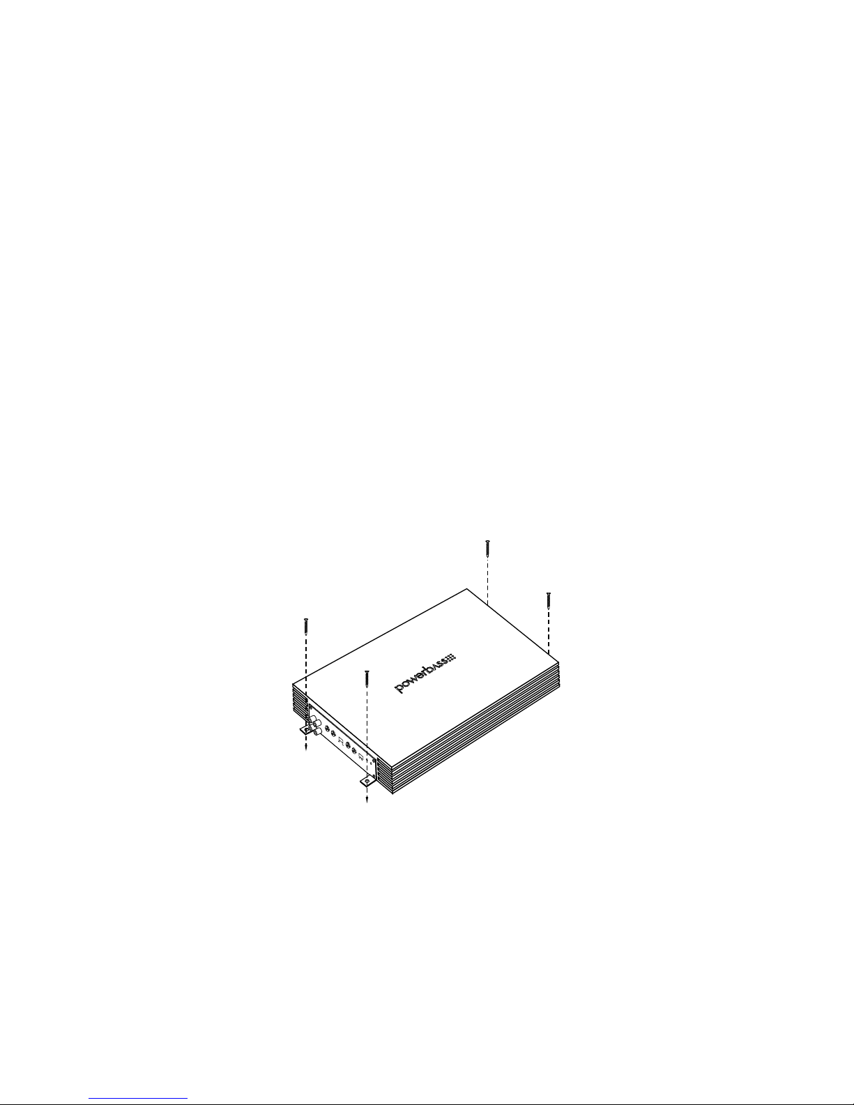
Fig.1 Mounting Amplifier
MOUNTING THE AMPLIFIER

MOUNTING LOCATION
Find a clear and well ventilated area to mount your amplifier that is unobstructed by any objects that will cause
harm or block ventilation. You may use the amplifier as a template and mark the four screw locations with a
felt tip pen. Use caution to make sure there are no objects behind the installation surface that may become
damaged during drilling.
If mounting under a seat, make sure there is at least 1-inch (2.5 cm) of space above the amplifier’s heatsink
to permit proper cooling.
The amplifier should be protected from exposure to moisture and direct sunlight. The best places to mount
your amplifier are: The floor of the trunk, under the driver’s seat, or on the back of the rear seat. For alternate
installation locations, please consult your authorized PowerBass Dealer.
*** WARNING ***
• Upside down mounting will compromise heat dissipation through the heatsink and
could engage the thermal protection circuit.
• Try to avoid mounting the amplifier on a subwoofer enclosure, as extended exposure
to vibration may cause malfunction of the amplifier.
• Don’t mount the amplifier so that the wire connections are unprotected or are subject to pinching or damage from nearby objects.
• The DC power wire must be fused at the battery positive (+) terminal connection.
Before making or breaking power connections at the amplifier power terminals,
disconnect the DC power wire at the battery end.
• The battery of the car audio system must be disconnected until the entire wiring and
installation is completed.
5
SPEAKER
FUSE
BATT
+ REMOTE GND
INPUTOUTPUT
GAIN
MIN MAX 0dB +18dB40Hz 250Hz
FULL LPF
LPF
BASS
EQ
MODE
REMOTE
POWER STATUS
CH1
CH2
CH1
CH2
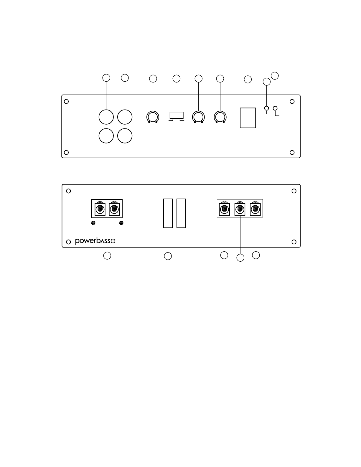
CONTROL PANEL LAYOUT
1 2
3 4 5 6
7
8
9
10
11
12
13
14
1. Line OUTPUT (RCA) Jacks
RCA style pass through output jacks allow for a signal to be sent to other amplifiers in a daisy-chain configuration. Only one Remote Bass Control can be used when multiple bass amplifiers are connected.
2. Line INPUT (RCA) Jacks
These RCA style input jacks are for use with source units that have RCA line level outputs. A source unit with
a minimum output of 500mV is required for proper operation. However, this input will accept levels up to
4Vrms.
3. GAIN Control
This control is used to match the input sensitivity of the amplifier to the particular source unit that you are
using up to 4 volts.
Fig.2 Panel Layout
 Loading...