


POWERSTOP-M
TRUCK RESTRAINT
INSTALLATION AND
OPERATION MANUAL
Job Name
Job Number
Serial Numbers
Systems, Inc.
P.O. Box 309
Germantown, WI 53022
Phone: (262) 255-1510
Fax: (262) 255-4199
11/96-10598

Table of Contents
Safety ................................................................................................................... 1
Safety Alert Symbols ...................................................................................... 1
General Safety Precautions ............................................................................ 1
Introduction ........................................................................................................ 2-3
Installation .......................................................................................................... 4-7
Mechanical Restraint Light and Sign Package ................................................ 7
Operating Instructions ........................................................................................ 8-9
Automatic Light Control .................................................................................. 8
Manual Light Control ....................................................................................... 9
No Lights ........................................................................................................ 9
Preventative Maintenance .................................................................................... 10
Troubleshooting Guide .................................................................................... 10-11
Parts Lists ..................................................................................................... 12-15

Safety
Safety Alert Symbols
This Safety Alert Symbol Means ATTENTION is Involved!
The Safety Alert Symbol identifies important safety messages on equipment, safety
signs, in manuals, or elsewhere. When you see this symbol, be alert to the possibility
of personal injury or death. Follow the instructions in the safety message.
WARNING
The use of the word “Warning” signifies the presence of hazards or unsafe practices
which could result in severe personal injury or death if instructions, including recommended precautions, are not followed.
CAUTION
The use of the word “Caution” signifies possible hazards or unsafe practices which
could result in minor injury, product or property damage if instructions, including
recommended precautions, are not followed.
General Safety Precautions
1. Do not operate this equipment until you read and understand the operating instructions and become thoroughly familiar with the equipment and
its controls.
2. Never operate a machine while a safety device or guard is removed or
disconnected.
3. Never remove Warning or Caution signs or decals on the equipment
unless they are to be replaced.
4. Do not start the equipment until all other personnel in the area have been
warned and have moved outside the operating zone.
5. Remove any tools or other foreign objects from the operating zone
before starting.
6. Keep operating zone free of obstacles that could cause a person to trip
or fall.
7. If so equipped, know EMERGENCY STOP procedures before operating.
8. Hydraulic and electrical power must be off when servicing equipment.
Note: For maximum protection, all power sources should be locked out
using a lock for which only you have the key. This prevents anyone
from accidentally turning on the power while you are servicing the
machine.
9. Keep alert and observe indicator lights and audible alarms.
10. Do not operate faulty equipment. Make certain proper service and
maintenance procedures have been performed.
11. Avoid placing fingers, hands, or any part of your body near moving parts.
This manual covers the mechanical truck restraint manufactured by
1

Introduction
Poweramp. Read the entire manual before installing and/or
operating the truck restraint. Poweramp mechanical truck restraints were designed to be compatible with almost all dock
designs. See Figures 1 and 2.
Figure 1
Pit Style Leveler
Poweramp mechanical restraints can be accompanied by a Dockalert light communication package
and sign kit. When installed and operated properly,
the mechanical restraint will allow the dock attendants to create a safer work environment in which to
work.
Figure 2
Edge of Dock
Figure 3
2

Introduction
Red
Light
Restraint
Stored
Green
Light
Restraint
Activated
Figure 4
Green
Light
Red
Light
When not in use, the restraint must be kept in
the stored position. If equipped with lights, the
light selector switch should be in either the
automatic or stored position depending on
restraint model. Units equipped with automatic
light operation should have the light control
switch placed in the automatic postion. Units
equipped with manual light operation must have
the light control switch placed in the position that
matches the restraint position. When the
mechanical truck restraint is stored, the outside
signal light is Green and the inside light is Red.
See Figure 4.
Operation of the restraint is from atop the dock.
A lifting hook is used from atop the dock to
release and store the restraint. To insure safety
in and around the loading dock, dock attendants
must perform the following tasks:
1. For those units equipped with manually operated lights, the operator must switch the light
control switch to the activated position prior to
loading/unloading. This will change the outside
signal light to Red.
Figure 5
Restraint Activated
Figure 6
2. After switching the light control to the activated
position, the dock attendant must activate the
mechanical truck restraint. This is done by
using the operating bar from atop the dock to lift
up on the release lever. The release lever is
located on the right side of the restraint when
viewed from atop the dock.
3. Once the restraint has been activated, the dock
attendant must visually inspect to assure that
the hook has properly engaged the ICC bar.
Proper engagement occurs when the hook is
able to travel vertically, contacting the bottom
edge of the horizontal member of the ICC bar,
CARGO
PALLET
without obstruction. Any missing, bent or
CARGO
mislocated ICC bars that do not allow for this
PALLET
vertical travel and/or contact are to be considered improperly engaged. When this condition
occurs, it is imperative that the proper personnel, especially the truck driver, be advised. The
truck/trailer must also be secured by another
method to insure safety. The restraint must be
stored and the selector switch (on the control
box) returned to the restraint stored position
after the loading/unloading process is complete.
3

Installation
These installation instructions were written to guide you during the installation
process. Please read and familiarize yourself with all sections of this manual prior to
starting the installation. If you have any questions about the installation or operation
of the Poweramp mechanical truck restraint, please consult the factory at (414) 2551510 before proceeding.
Open and inspect all material upon delivery. Check contents against packing slip.
Report any damage or shortages immediately to the truck line responsible.
Gather all material required for installation of restraint. Anchor kit Part #2103- 0001
supplied with the restraint consists of the following:
Item Qty. Part # Description
1 2 2101-0174 Rod 1" - 8UNL GR5 x 12
2 2 2101-0175 Nut 1" - 8UNL GR5
3 6 2101-0108 Anchor 5/8" x 5"
4 2 2101-0086 Washer
Additional material required to complete the restraint installation not supplied by
Poweramp consist of the following:
Item Qty. Part # Description
1 1 2101-0177 Adhesive cartridge Rawl# 8403
2 1 2101-0178 Nozzle Rawl# 7908
3 1 2101-0179 Injection tool Rawl# 8406
4 1 N/A 1" nylon bottle brush
Items listed above with Poweramp part numbers may be purchased separately. Each
adhesive cartridge should be adequate to install three restraints. Nozzles are not
reusable.
1. Correct installation of the Poweramp mechanical truck restraint requires
attachment to a concrete drive greater than 6" thick. If other conditions
exist, such as asphalt, a 48" wide by 48" long x 8" deep pad using a minimum of 4000 psi concrete must be poured.
2. Because of the restraint’s unique design, its mounting location is referenced
off the bumper face. This insures its compatibility with almost all dock
designs. Properly installed bumpers, in good repair, are essential to a safe
dock. If inspection of bumpers shows them to be missing, damaged or
severely worn, contact your Poweramp representative to obtain replacements.
3. Position the Poweramp mechanical truck restraint in the center of the dock/
door opening with the primary (1") anchor holes located 1/2" ahead of the
bumper face as shown in Figure 7. After locating and marking the primary
anchor locations (qty. 2) on the drive surface, drill 1-1/8" diameter holes 8-81/2" deep. If drill breaks through concrete at a depth of less than 6", consult
factory. The remaining (6) 3/4" anchor holes can be drilled at this time.
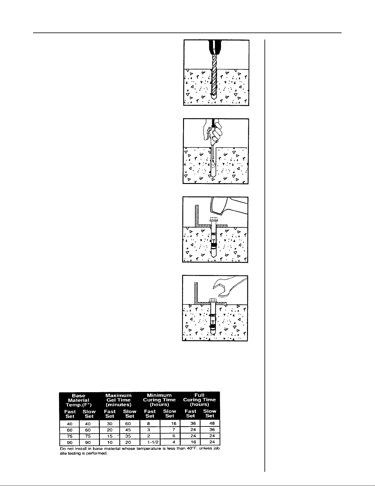
4. Preparation of the anchor hole is necessary to assure a long lasting installation. Prepare the 1-1/8" diameter holes in the following manner:
4

Installation
Plumb Line
1" Main Achors
Figure 7
A. Blow the hole clean with compressed air, brush out
using 1" nylon brush, blow clean again. Holes
should be clean and sound. They may be dry or
damp, but should be free of standing water or frost.
Be sure rod fits into hole. If larger hole is required,
the diameter should be as close as possible to the
rod diameter.
B. Fill the hole approximately half way with adhesive
mortar starting from the rear of the hole. Slowly
withdraw the nozzle as the hole fills to avoid creating
air pockets within the hole.
C. Push the threaded rod into the hole while turning
slightly to insure positive distribution of the adhesive
mortar. Be sure rod is fully seated at the bottom of
the hole and that the mortar has flowed from the top
of the hole. If an insufficient amount of adhesive is
placed in the hole, indicated by a lack of filling to the
top of the hole when the rod is inserted, the rod must
be extracted, additional adhesive added and rod
reinserted. The threaded rod used must be free of
dirt, grease, oil or other foreign material. Allow the
adhesive mortar to cure for the time specified in chart
prior to applying any load. See Figure 10. Do not
distribute or load the anchor until it is fully cured.
Handling can be simplified and line up insured if restraint is
positioned over holes before rods are inserted for the final time.
After adhesive has cured, adjust restraint using a bubble level, so
the back is perpendicular. Shim under bottom as needed.
Figure 8
Install remaining six anchors using the following procedure:
5
Installation
Using the proper diameter bit, drill a hole into the
base material to a depth of at least 1/2" or one
anchor diameter deeper than the embedment
required. The tolerances of the drill bit used
should meet ANSI Standard B94.12.
Blow the hole clean of dust and other material.
Remove the inspection tag from the anchor and
position the fixture. Do not expand the anchor
prior to installation.
Drive the anchor through the fixture into the
anchor hole until the bolt head is firmly seated
against the fixuture. Be sure the anchor is driven
to the required embedment depth.
Tighten the anchor by turning the head 3 to 4
turns.
Figure 9
Figure 10
6

Installation
If your mechanical restraint is equipped with a Dock alert light communication package, please continue to follow the installation instructions. If your unit is not equipped
with lights, please turn to the operation section, page 9.
INSTALLATION OF ELECTRICAL COMPONENTS
When equipped with a light communication package, the mechanical restraint includes a prewired control box, outside light box, and (2) outside truck driver signs.
Components such as conduit, fittings, anchors, etc. are supplied by others. Quality
workmanship using materials approved by code is required.
A typical installation will require mounting of the outside light box as shown in Figure
11. The control box mounting is generally inside the building on the left hand side of
the overhead door.
Flexible conduit supplied with the mechanical restraint must be connected to a
junction box (supplied by others). The location of the junction box may vary. Whenever possible, the junction box should be placed high on the outside wall or on the pit
floor to avoid flooding. The junction box and associated conduit are to be supplied by
others. Wiring to and from the restraint must be limited to restraint wiring only. Do
not run high voltage lines through the same conduit as restraint wires.
Figure 11
INSTALLATION OF SIGN
Because of the many ways signs can be mounted, hardware is not supplied. Mount
the sign(s) on the right hand side, as viewed by truck driver, of restraint. The sign is
usually mounted near the outside signal light permitting the truck driver to read signs
from truck.
Figure 11 provides a suggested location for sign mounting. Good workmanship and
quality materials should be used.
NOTES:
1. Some docks may have dock/truck seals (or shelters) installed or planned. Sign
location and mounting should be studied before proceeding.
2. If required, signs may be trimmed for fit. NEVER cut or eliminate sign letters/
words.
7

Operation
The Poweramp mechanical truck restraint was designed to work in conjunction with other dock equipment allowing the dock attendant to create a safer
working environment.
Before operating the equipment, be sure the rear of the trailer has been
parked tight against the face of both dock bumpers. If your loading dock is
equipped with a dock leveler, the hinged lip must be in the pendant, stored
position prior to operating the restraint.
Operation of the restraint will vary slightly depending on whether your
restraint is equipped with a light communication package. Always operate
the truck restraint from atop the dock using the operating bar provided to
prevent personal injury.
Prior to operating the equipment for the first time, check to see if the installers moved the release lever shipping bolt to the operating position. The
release lever shipping bolt is located directly above the release lever. Failure
to move this bolt will result in a non-operational restraint.
OPERATION WITH AUTOMATIC LIGHTS
The following procedure can be used for operating Poweramp mechanical
restraints equipped with automatic lights.
1. Verify that the light control switch is in the automatic position, and that a
red light is illuminated inside with a green light illuminated outside.
2. Verify that the trailer is parked tight against both bumpers.
3. Insert one end of the operating bar under the release lever on the left
hand side of the restraint.
4. Lift up on the operating bar, causing the release lever to rotate, thus activating
the restraint. With the restraint activated, the restraint arm will move vertically.
5. Visually inspect and confirm that the truck restraint arm has travelled vertically
and has engaged the horizontal member of the ICC bar. Visually verify that the
outside light has switched to red and that the activated light inside is illuminated.
6. Return operating bar to its storage bracket.
7. Activate dock leveler and proceed to load/unload.
8. When loading/unloading of truck is completed, return the dock leveler to the
stored position.
9. Insert operating bar into the top of the slide track on the truck restraint.
10. Push the restraint arm down until the release lever locks on the carriage body.
11. Verify that the inside light has changed and that the stored light is now illuminated.
12. Return the operating bar to the storage rack.
8

Operation
OPERATION WITH MANUAL LIGHTS
1. Switch the inside control box light control switch to the released position. Verify
that the green light has illuminated.
2. Verify that the trailer is parked tight against both bumpers.
3. Insert one end of the operating bar under the release lever on the left hand side of
the restraint.
4. Lift up on the operating bar, causing the release lever to rotate, thus activating the
restraint. With the restraint activated, the restraint arm will move vertically.
5. Visually inspect and confirm that the truck restraint arm has travelled vertically
and has engaged the horizontal member of the ICC bar. Visually verify that the
outside light has switched to red and that the activated light inside is illuminated.
6. Return operating bar to its storage bracket.
7. Activate dock leveler and proceed to load/unload.
8. When loading/unloading of truck is completed, return the dock leveler to the
stored position.
9. Insert operating bar into the top of the slide track on the truck restraint.
10. Push the restraint arm down until the release lever locks on the carriage body.
11. Switch the inside control box light control switch to the stored position. Verify
that the red light has illuminated.
OPERATION WITHOUT LIGHTS
1. Verify that the trailer is parked tight against both bumpers.
2. Insert one end of the operating bar under the release lever on the left hand side of
the restraint.
3. Lift up on the operating bar, causing the release lever to rotate, thus activating the
restraint. With the restraint activated, the restraint arm will move vertically.
4. Visually inspect and confirm that the truck restraint arm has travelled vertically
and has engaged the horizontal member of the ICC bar.
5. Return operating bar to its storage bracket.
6. Activate dock leveler and proceed to load/unload.
7. When loading/unloading of truck is completed, return the dock leveler to the
stored position.
8. Insert operating bar into the top of the slide track on the truck restraint.
9. Push the restraint arm down until the release lever locks on the carriage body.
10. Return the operating bar to the storage rack.
9

Maintenance/Troubleshooting
MAINTENANCE
1. Good housekeeping practice is the most commonly needed truck restraint
requirement. Shipping and receiving docks are notorious for having wood
scraps, steel banding and other debris laying at the front of the dock.
Daily patrol truck restraint area and clean up dock.
2. Depending on the type of application, the truck restraints usually require
lubrication every three months. Lubricate back track with an anti-seize
lubricant. Lubricate linkage with 30 wt. oil.
3. IMPORTANT: Inspect daily and test the inside and outside signal lights.
THEY MUST WORK. Replace broken light/bulb as required.
4. Repair or replace signs if required.
5. IMPORTANT: Truck restraint must be protected by dock bumpers.
Worn, torn, loose or missing bumpers must be replaced. Contact your
local representative for replacement bumpers.
6. Perform operation/test after all repairs and adjustments.
TROUBLESHOOTING
WARNING: Do not allow personnel or materials in operating path of restraint when
carriage is in stored position. When released, carriage raises at a sufficient velocity to
cause severe injury. Perform service with unit raised.
1. If carriage will not raise:
A. Check side release lever--it may be bound and not releasing.
B. Check restraint body for debris which may bind operation.
C. Check for broken lifting springs.
D. Check link joints for missing or bent shoulder bolts, pins or excessive
wear.
E. Joints are permanently lubricated bushings and should not require oiling.
However, rubbing surfaces of links should be lubricated per maintenance
section of this manual.
2. If carriage will not lower or lock down:
A. Check side release lever--it may be bound and not engaging.
B. Check restraint body for debris which may bind operation.
C. Check link joints for missing or bent shoulder bolts, pins or excessive
wear.
D. Joints are permanently lubricated bushings and should not require oiling.
However, rubbing surfaces of links should be lubricated per maintenance
section of this manual.
10
E. On occasion, the truck may move forward, trapping the ICC bumper
maintaining a positive engagement. To unlock the restraint carriage, it
may be necessary for the truck to back up.

Maintenance/Troubleshooting
3. If signal lights, either inside or outside, fail to operate or operate incorrectly:
NOTE: Both sets of lights are controlled from the same control box
switch.
A. Check bulbs. Replace as required.
B. Check on/off switch. Repair or replace if needed.
C. Check electrical power source.
4. If restraint is equipped with automatic light control and lights do not
change properly, test relay in control box and proximity switch on restraint
for proper operation.
11

23
12
25
30
3
14
14
15
9
5
7
18
9
11
10
ITEM #14 IS COMMON
TO ALL PIVOT POINTS
14
15
9
2
17
14
17
19
5
28
16
29
6
16
6
14
13
8
21
1
22
31
21
OPTIONAL
W
x
x
x
x
x
x
A
x
x
x
x
x
R
x
x
x
x
x
N
x
x
x
x
x
x
x
x
x
x
x
x
x
x
x
x
x
x
x
x
x
x
x
x
x
x
x
x
x
x
x
x
x
x
x
x
x
x
x
x
x
x
x
x
x
x
x
x
x
x
x
x
x
x
x
x
x
x
x
x
x
x
x
x
x
x
x
x
x
x
x
x
x
x
x
x
x
x
x
x
x
x
x
x
x
x
x
x
x
x
x
x
x
x
x
x
x
x
x
x
x
x
x
x
x
x
x
x
x
x
x
x
x
x
x
x
x
x
24
32
Figure 12
I
N
x
x
x
G
x
x
x
x
x
x
x
x
x
x
x
x
x
x
x
x
x
x
x
x
x
x
x
x
x
x
x
x
x
x
x
x
x
x
x
x
x
x
x
x
x
x
x
x
x
x
x
x
x
x
x
x
x
x
26
4
20
12

BILL OF MATERIALS
ITEM QTY PART NUMBER DESCRIPTION
1 1 9414-0034 BASE WELDMENT
*2 1 0961-0148 PROXIMITY SWITCH
3 1 9413-0049 RESTRAINT WELDMENT
4 1 9411-0023 SHROUD
5 4 9412-0148 BAR LINK - TAPPED CENTER
6 4 9412-0149 BAR LINK
7 1 9412-0180 RELEASE LEVER
8 2 0192-0053 BRUSH - WEATHERSEAL
9 3 9202-0042 PIN - LONG
10 2 9413-0044 SPRING PLATE WELDMENT
11 2 0941-0011 SPRING EXTENSION
12 1 0522-0002 SPRING - RESTRAINT GUIDE
13 1 9412-0160 ROLLER
14 21 9461-0006 FLANGED SHOULDER BEARING - BRONZE
15 5 2101-0165 SOCKET HEAD SHOULDER SCREW
*16 2 2101-0182 PHILLIPS SCREW = #8 X 1-1/4
17 2 9202-0043 PIN - SHORT
18 10 2101-0189 E CLIP
19 1 2101-0039 HEX HEAD NUT
20 2 2101-0057 HEX HEAD CAPSCREW
21 2 0192-0052 TRACK - WEATHERSEAL
22 6-8 2101-0180 SCREW - PHILIPS
23 1 2103-0001 ANCHOR KIT
*24 2 0192-0056 BRUSH WEATHERSEAL - OPTIONAL
25 2-3 2101-0085 FLAT WASHER
26 1 5455-0005 OPERATING LEVER
27 1 2101-0181 SOCKET HEAD SHOULDER SCREW
*28 2 2101-0156 LOCK WASHER - #8
29 1 2101-0018 HEX HEAD CAP SCREW
30 2 9412-0161 BOSS
*31 2 2101-0189 BRUSH WEATHERSEAL - OPTIONAL
*32 1 9411-0025 SHROUD - TAPERED - OPTIONAL
* OPTIONAL:
1. ITEM #2, 16 & 28 IS ADDED
2. ITEM #24, 31 & 32 REPLACES ITEM #4 & 8
ITEM #22 QUANITY CHANGES FROM 6 TO 8
13

Figure 13
14

BILL OF MATERIALS
ITEM QTY. PART NUMBER DESCRIPTION
1 1 7154-0002 SIGNAL LIGHT HOUSING ASSY.
2 2 7153-0006 LIGHT ASSEMBLY
3 2 3051-0046 LAMP (GE 10C7DC)
4 1 7151-0002 RED LENS
5 1 7151-0003 GREEN LENS
6 2 7151-0026 LENS GASKET
7 2 7151-0011 SNAP RING
8 2 7151-0006 LIGHT ASSEMBLY GASKET
9 1 7152-0006 BACK PLATE
10 1 1751-0034 CAUTION SIGN - MIRRORED
11 1 1751-0033 CAUTION SIGN
12 1 2751-0125 CONTROL BOX
15
 Loading...