

PowerHook
Truck Restraint
Owner’s/User’s Manual
Printed in U.S.A.
Copyright © 2003
POWERAMP • Division of Systems, Inc. • W194 N11481 McCormick Drive • Germantown, WI 53022
800.643.5424 • fax: 262.255.5917 • www.docksystemsinc.com • techservices@docksystemsinc.com
Manual No. 4111-0010
February 2011

Table of Contents
Page
Safety
Recognize Safety Information ............................................................. 1
General Operational Safety Precautions ............................................ 1
Safety Decal’s ........................................................................................ 5
Owner’s/User’s Responsibilities ......................................................... 7
Introduction
General Information .............................................................................. 9
Component Identification .....................................................................10
Installation
Model identification ..............................................................................11
KS4 Installation .....................................................................................10
KS5 Installation .................................................................................... 13
KS6 and KS7 ........................................................................................ 16
Operation
Operating Instructions ....................................................................... 21
Sequence of Operation ....................................................................... 22
Maintenance
Service Dock Leveler/Restraint Safely ............................................. 24
Periodic Maintenance ......................................................................... 25
Adjustment And Testing
Testing PowerHook Operating Range .............................................. 27
Adjust Powerhook Operating Range ................................................ 28
Pressure Relief Adjustment ............................................................... 30
Adjust Dock Leveler and Truck Restraint Interlock ........................ 32
Adjust Auto Return To Dock (ARTD) ................................................ 33
Troubleshooting
Troubleshooting Charts ..................................................................... 36
Programing PLC’s ............................................................................... 45
Forcing Solenoids ............................................................................... 46
Wiring Diagrams ................................................................................. 48
Parts
Controls ............................................................................................... 50
PowerHook Guide Track Components ............................................. 51
PowerHook Components ................................................................... 52
PowerHook Valve Body Assembly .................................................... 53
Power Pack Assembly ........................................................................ 54
Pressure Differential ........................................................................... 56
Miscellaneous
Customer Information ........................................................................ 57
Warranty ................................................................................ Back Cover
4111-0010 — February 2011
2
4111-0010 — Nov 2010

SAFETY
Recognize Safety Information
Safety-Alert Symbol
The Safety-Alert Symbol identifies important safety
messages on equipment, safety signs, in manuals,
or elsewhere. When you see this symbol, be alert to
the possibility of personal injury or death. Follow the
instructions in the safety message.
The use of the word DANGER signifies the presence
of an extreme hazard or unsafe practice which will
most likely result in severe injury or death.
General Operational Safety
Precautions
Read and understand the operating instructions and
become thoroughly familiar with the equipment and its
controls before operating the dock leveler.
Never operate a dock leveler while a safety device or
guard is removed or disconnected.
Never remove DANGER, WARNING, or CAUTION
signs or Decal’s on the equipment unless replacing
them.
The use of the word WARNING signifies the
presence of a serious hazard or unsafe practice
which may result in serious injury or death.
The use of the word CAUTION signifies possible
hazard or unsafe practice which could result in
personal injury.
IMPORTANT
The use of the word IMPORTANT is to draw
attention to a procedure that needs to be followed to
prevent machine damage.
e
g Zon
eratin
p
O
e
n
Zo
ting
era
Op
Do not start the equipment until all unauthorized
personnel in the area have been warned and have
moved outside the operating zone.
Remove any tools or foreign objects from the operating
zone before starting.
Keep the operating zone free of obstacles that could
cause a person to trip or fall.
4111-0010 — February 2011
4111-0010 — Nov 2010
1
1

SAFETY
Operational Safety Precautions
Learn the safe way to operate this equipment. Read and understand the manufacturer’s
instructions. If you have any questions, ask your supervisor.
Stay clear of dock leveling device when freight
carrier is entering or leaving area.
Do not move or use the dock leveling device if
anyone is under or in front of it.
Keep hands and feet clear of pinch points. Avoid
putting any part of your body near moving parts.
Chock/restrain all freight carriers. Never remove
the wheel chocks until loading or unloading is
finished and truck driver has been given permission
to drive away.
Do not use a broken or damage dock leveling
device. Make sure proper service and maintenance
procedures have been performed before using.
Make sure lip overlaps onto trailer at least 4 in.
(102 mm).
Keep a safe distance from both side edges.
4111-0010 — February 2011
2
2
4111-0010 — Nov 2010

Do not use dock leveling device if freight carrier is
too high or too low.
SAFETY
Do not overload the dock leveling device.
Do not operate any equipment while under the
influence of alcohol or drugs.
Do not leave equipment or material unattended on
dock leveling device.
4111-0010 — February 2011
4111-0010 — Nov 2010
3
3

SAFETY
Maintenance Safety Precautions
Hydraulic and electrical power must be OFF when
servicing the equipment. For maximum protection,
use an OSHA approved locking device to lock
out all power sources. Only the person servicing
the equipment should have the key to unlock the
device.
ALWAYS disconnect electrical power source and
ground wire before welding on dock leveler.
DO NOT ground welding equipment to any hydraulic
or electrical components of the dock leveler. Always
ground to the dock leveler frame.
Failure to follow these instructions may result in
damage to dock leveler and/or serious personal
injury or death.
DO NOT grind or weld if hydraulic fluid or other
flammable liquid is present on the surface to be
ground or welded
DO NOT grind or weld if un contained hydraulic fluid
or other flammable liquid is present. Stray sparks
can ignite spills or leaks near the work area. Always
clean up the oil leaks and spills before proceeding
with grinding or welding.
Always post safety warnings and barricade
the work area at dock level and ground level
to prevent unauthorized use of the unit before
maintenance is complete.
The maintenance prop must be in the upright
“service” position when working under the dock
leveler. For maximum protection, use an OSHA
approved locking device to lock the maintenance
prop in the service position. Only the person
servicing the equipment should have the key to
unlock the device.
Always keep a fire extinguisher of the proper type
nearby when grinding or welding.
Failure to follow these instructions may result in
serious personal injury or death.
ALWAYS stand clear of dock leveler lip when
working in front of the dock leveler. Failure to do this
may result in serious personal injury or death.
4111-0010 — February 2011
4
4
4111-0010 — Nov 2010

Every 90 days (quarterly) inspect all safety labels and tags
to ensure they are on the dock leveler and are easily legible. If any are missing or require replacement, please call
1-800-643-5424 for replacements.
C
C
6666<<<<66667777((((00006666,,,,1111&&&&
1751-0727
1751-0138
CRUSH HAZARD
Maintenance prop must
support leveler behind bar.
Do not force maintenance
prop forward of bar to
support lip. Refer to
owner’s/user’s manual for
proper use. Failure to
comply will result in
death or serious injury.
DANGER
1751-0727
DANGER
!
CRUSH HAZARD
DO NOT REMOVE hydraulic cylinder until leveler is
safely supported by maintenance prop. Refer to
owner’s/user’s manual for proper maintenance
procedure. Failure to comply will result in death or
serious injury.
CRUSH HAZARD
Do not work under dock leveler unless this maintenance prop has been secured in the
upright position. See owner’s/user’s manual for proper procedures. Failure to comply
will result in death or serious injury.
DANGER
1751-0729
CRUSH HAZARD
Rotate prop to maintenance
position.
Open the pin latch
and insert through the
maintenance prop housing.
Close the pin latch to secure
prop. Use every time dock
leveler is serviced. Failure to
comply will result in death
or serious injury.
DANGER
1751-0731
CRUSH HAZARD
DO NOT ENTER PIT unless dock leveler is
safely supported by maintenance prop. Place
barriers on driveway and dock floor to indicate
service work being performed. Refer to
owner’s/user’s manual for proper maintenance
procedures. Failure to comply will result in death
or serious injury.
DANGER
1751-0726
1751-0729
1751-0731
1751-0726
Unsupported dock leveler
ramps can lower unexpectedly.
Before allowing vehicle to leave
the dock always:
! Ensure that no equipment,
material or people are on the
dock leveler.
! Return the dock leveler to its
stored position at dock level.
Failure to follow posted instructions will result in death or serious injury.
SAFETY INFORMATION
Call 262.255.1510 for replacement placards, warning labels, or owner’s/user’s manuals.
Operation
1. Read and follow all instructions and
warnings in the owner’s/user’s
manual.
2. Use of dock leveler restricted to
trained operators
3. Always chock trailer wheels or
engage truck restraint before
operating dock leveler or beginning to
load or unload.
4. Never use hands or equipment to
move the ramp or lip
5. Before activating dock leveler:
¥ Ensure trailer is backed in against
bumpers.
¥ Remove any end loads if required.
¥ Check trailer alignment to avoid lip
interference. If lip does not lower to
trailer bed, reposition vehicle.
6. Ensure that truck bed supports
extended lip or the leveler frame
supports the ramp before driving on
ramp.
7. Stay clear of hinges and front and
sides of moving dock leveler.
8. Never use damaged or
malfunctioning dock leveler. Report
problems immediately to supervisor.
Maintenance/Service
1. Read and follow all instructions,
warnings and maintenance schedules
in the owner’s/user’s manual.
2. Maintenance/Service of dock leveler
restricted to trained personnel.
3. Place barriers on the driveway and on
dock floor to indicate service work is
being performed.
4. DO NOT ENTER PIT unless dock
leveler is securely supported by
maintenance prop.
5. If electrically powered turn off and use
OSHA lockout/tagout procedures.
DANGER
DO NOT
FORK THIS SIDE
FORK
HERE
1751-0730 (x2)
(decal placed in same position on both sides)
(decal placed in same position on both sides)
(decal placed in same position on both sides)
1751-0329 (x2)
1751-0330 (x2)
Dock Leveler Safety Decal’s
SAFETY
4111-0010 — February 2011
4111-0010 — Nov 2010
5
5
SAFETY
Every 90 days (quarterly) inspect all safety labels and tags
to ensure they are on the dock leveler and are easily legible. If any are missing or require replacement, please call
1-800-643-5424 for replacements.
CRUSH HAZARD
Maintenance prop must
support leveler behind bar.
Do not force maintenance
prop forward of bar to
support lip. Refer to
owner’s/user’s manual for
proper use. Failure to
comply will result in
death or serious injury.
DANGER
1751-0727
Unsupported dock leveler
ramps can lower unexpectedly.
Before allowing vehicle to leave
the dock always:
! Ensure that no equipment,
material or people are on the
dock leveler.
! Return the dock leveler to its
stored position at dock level.
Failure to follow posted instructions will result in death or serious injury.
SAFETY INFORMATION
Call 262.255.1510 for replacement placards, warning labels, or owner’s/user’s manuals.
Operation
1. Read and follow all instructions and
warnings in the owner’s/user’s
manual.
2. Use of dock leveler restricted to
trained operators
3. Always chock trailer wheels or
engage truck restraint before
operating dock leveler or beginning to
load or unload.
4. Never use hands or equipment to
move the ramp or lip
5. Before activating dock leveler:
¥ Ensure trailer is backed in against
bumpers.
¥ Remove any end loads if required.
¥ Check trailer alignment to avoid lip
interference. If lip does not lower to
trailer bed, reposition vehicle.
6. Ensure that truck bed supports
extended lip or the leveler frame
supports the ramp before driving on
ramp.
7. Stay clear of hinges and front and
sides of moving dock leveler.
8. Never use damaged or
malfunctioning dock leveler. Report
problems immediately to supervisor.
Maintenance/Service
1. Read and follow all instructions,
warnings and maintenance schedules
in the owner’s/user’s manual.
2. Maintenance/Service of dock leveler
restricted to trained personnel.
3. Place barriers on the driveway and on
dock floor to indicate service work is
being performed.
4. DO NOT ENTER PIT unless dock
leveler is securely supported by
maintenance prop.
5. If electrically powered turn off and use
OSHA lockout/tagout procedures.
DANGER
DO NOT
FORK THIS SIDE
FORK
HERE
CRUSH HAZARD
Do not work under dock leveler unless this maintenance prop has been secured in the
upright position. See owner’s/user’s manual for proper procedures. Failure to comply
will result in death or serious injury.
DANGER
1751-0788
CRUSH HAZARD
Open the pin latch and insert
through the maintenance
prop housing and prop
completely. Close the pin latch
to secure prop. Use every
time dock leveler is serviced.
Failure to comply will result
in death or serious injury.
DANGER
1751-0789
CRUSH HAZARD
DO NOT ENTER PIT unless dock leveler is
safely supported by maintenance prop. Place
barriers on driveway and dock floor to indicate
service work being performed. Refer to
owner’s/user’s manual for proper maintenance
procedures. Failure to comply will result in death
or serious injury.
DANGER
1751-0726
1751-0727
1751-0730 (x2)
1751-0788
1751-0789
1751-0726
CRUSH HAZARD
Do not remove main springs until leveler is safely supported by
maintenance prop. Main springs contain stored energy. Be sure
springs are fully unloaded and ends are loose before removal. Refer
to owner’s/user’s manual for proper maintenance procedure. Failure
to comply will result in death or serious injury.
DANGER
1751-0728
1751-0728
(decal placed in same position on both sides)
(decal placed in same position on both sides)
(decal placed in same position on both sides)
1751-0329 (x2)
1751-0330 (x2)
Dock Leveler Safety Decal’s
6
4111-0010 — Nov 2010

OWNER’S/USER’S RESPONSIBILITIES
1. The owner/ user should recognize the inherent dangers of the interface between the loading
dock and the transportation vehicle. The owner/ user should, therefore, train and instruct
all operators in the safe operation and use of the loading dock equipment in accordance
with manufacturer’s recommendations and industry standards. Before operation of the
equipment, all operators shall read, understand and be familiar with all functions of
equipment as described in the owner’s/user’s manual.
2. The manufacturer shall provide to the initial purchaser all necessary information with regards
to: Safety Information, Operation, Installation and Safety Precautions, Recommended
Initial and Periodic Inspections Procedures, Planned Maintenance Schedule, Product
Specifications, Troubleshooting Guide, Parts Break Down, Warranty Information and
Manufacturers Contact Information. The owner/ user shall be responsible to verify that this
information is available and received as well as proper instructions, training and familiarity of
the equipment for all operators has been completed. Owner’s/User’s shall actively maintain,
update and re train all operators on safe working habits and operations of the equipment.
3. It is recommended when the transportation vehicle is positioned correctly in the dock opening
and in contact with both bumpers, there shall be a minimum of 4.00 inches (100mm) overlap
of the leveling device and the transportation vehicle at all times during the loading and
unloading process.
4. Name plates, placards, decals, instructions and posted warnings shall not be obscured from
the view of the operator or maintenance personnel for whom such warnings are intended
for. Contact manufacturer for any replacements.
5. Manufacturer’s recommended periodic maintenance and inspection procedures in effect at
the date of shipment shall be followed at all times. Written documentation of maintenance,
replacement parts or damage should be retained. In the event of damage notification to the
manufacturer is requested.
6. Any modifications or alterations of loading dock equipment shall only be done with prior
written approval from the original equipment manufacturer.
7. 7. When industrial moving devices are being used in the loading or unloading of product
from the transportation vehicle, this vehicle shall have the brakes and wheel chocks applied
appropriately or all other positive restraining device shall be fully utilized.
8. Loading dock safety equipment should never be used outside of its intended use, range, or
capacity. Please consult the manufacturer if you have any questions as to the use, range
or capacity of the equipment.
9. When selecting loading dock safety equipment, it is important to consider not only present
requirements but also future plans and any possible adverse conditions, environments or
use.
4111-0010 — Nov 2010
7

INTRODUCTION
General Information
Congratulations on your choice of a Poweramp PowerHook truck restraint. This manual covers the
PowerHook Truck restraint operating system.
Designed by Poweramp to be a marvel of simplicity and
efficiency, your truck restraint, when properly installed,
will provide many years of trouble-free performance
with an absolute minimum of maintenance. Its
revolutionary hydraulic system efficiently controls
and operates every function. To obtain maximum
performance and longest possible use, a simple
program of preventive maintenance is recommended
and is outlined in this manual.
The PowerHook is the original truck restraint to seek,
find and maintain a tight, continuous hold on the RIG
(Rear Impact Guard) bar, effectively eliminating “trailer
creep”. As an optional safety feature, the dock leveler
and truck restraint can be interlocked, preventing
operation of the dock leveler until the hook engages
the truck RIG bar.
The truck restraint is firmly anchored in the loading
dock pit for maximum holding power. The hook
remains protected behind the pit wall until activated.
The PowerHook restraint is designed to withstand a
pulling force in excess of 35,000 lbs.
When not in use, PowerHook stores in a pit, concealed
and out of the way, enabling dock workers to clear the
driveway approach of snow or debris.
The PowerHook truck restraint comes equipped with
an electrical control panel, which allows push button
operation of the truck restraint functions.
When combining a Poweramp dock leveler with a
PowerHook truck restraint, the control panel will allow
for operation of both units in the same control panel.
Each PowerHook, Poweramp dock leveler and control
panel has been factory pre wired and tested to ensure
satisfactory operation.
To illustrate which connections are to be made in the
field at installation, electrical drawings are included
with each order or by contacting Poweramp Technical
Services.
Once again, thank you and congratulations on your
purchase of a Poweramp PowerHook truck restraint.
Due to ongoing product improvement, some parts have changed, along with operation and trouble shooting
methods. This manual describes these changes. For further assistance, please contact:
Poweramp Technical Service at 800-643-5424 or techservices@docksystemsinc.com
8
4111-0010 — Nov 2010

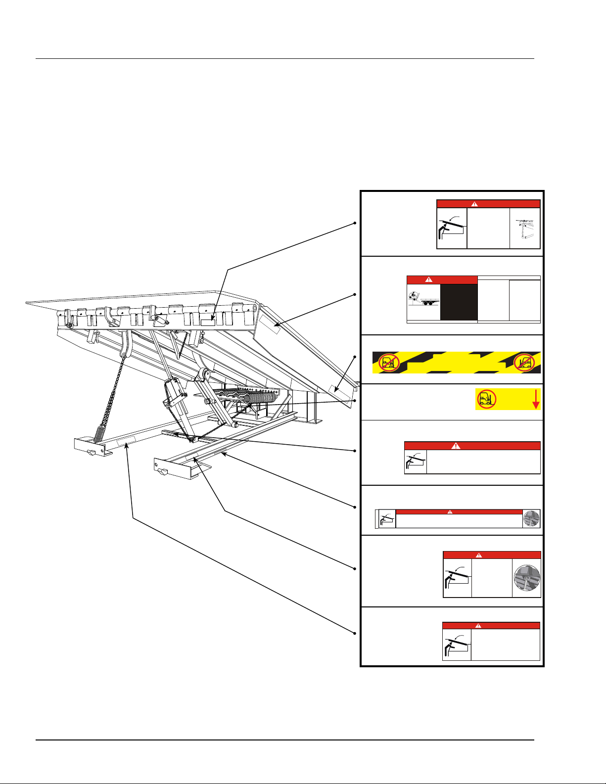
Component Identification
INTRODUCTION
J
I
H
A — Regeneration Valve
B — Hook Cylinder
C — Hook
A
G
D — Guide Track-Slide Rod
E — Guide Track
F — Sensor, Magnetic Reed Switch
(Replaces Proximity Switch)
B
F
DE
G — Positioning Cylinder
H — Guide Track Harness - Includes 4 Magnetic
Reed Switches, Assembled
I — Hook Lowered Sensor Target
C
J--Pressure Differential
Valve
New Telemecanique “TWIDO” Programmable Logic Controller
4111-0010 — Nov 2010
9

INSTALLATION
This manual covers three models of PowerHook® truck restraints: KS4, KS5, KS6. See Figures 1, 2, and 3. In
addition to the hydraulically actuated truck restraint, PowerHook® has a programmable electronic controller and
Dock alert, a dock communication systems
The installation instructions are to be used as basic guide lines for proper installation. There may be different
techniques to install the levelers, but installation must conform to the correct welding and shimming as shown in
the oweners/users manual
Fig. 1
KS4 PowerHook
The PowerHook® KS4 box-type truck
restraint is ideally suited for Vertical
Leveler installations. The larger box form
with insulated lid is fully assembled and
ready to be poured in place during the
construction process.
®
Fig. 2
KS5 PowerHook
®
The PowerHook® KS5 pan-type truck
restraint is an economical retrofit for dock
levelers. The fully assembled pan ships
complete with all the concrete anchors
needed to insure a secure installation.
Fig. 3
KS6 PowerHook
®
The PowerHook® KS6 free-standing
frame type truck restraint is fully installed
and integrated into full height leveler
stand. It’s easy to install...just weld it into
position and run power to it.
10
4111-0010 — Nov 2010

KS4 INSTALLATION
These installation instructions were written for retrofitting
a Poweramp® hydraulic dock leveler with integral power
pack with a PowerHook® KS4 Vehicle Restraint.
If you are not adding the PowerHook® to an existing
dock leveler, some steps may not be needed or
additional procedures may be required, as follows:
• When installing in new construction (i.e., new
PowerHook and new Poweramp hydraulic leveler
in a newly prepared pit), skip steps 1 through 5.
Platform modifications, step 5 were completed prior
to shipment.
• When installing PowerHook with a Poweramp
hydraulic dock leveler which is powered by remote
power pack or a Centra Power® system, refer to
the manuals provide with those units as well as to
page 15 in this manual.
• When installing Powerhook with a mechanical
dock leveler or a hydraulic dock leveler
manufactured by another company, the PowerHook
must be equipped with a remote hydraulic power
pack. See page 15 of this manual.
INSTALLATION
Post safety warnings and barricade the work area at
dock level and ground level to prevent unauthorized
use of the dock leveler before installation has been
completed.
Failure to follow the installation instructions can
result in damage to dock leveler, the facilities, and/
or serious personal injury or death.
IMPORTANT
DO NOT connect the dock leveler electrical wiring
and ground connections until all welding has been
completed.
DO NOT ground welding equipment to any hydraulic
or electrical components of the dock leveler. Always
ground welding equipment to the dock leveler frame,
NEVER to the platform.
Failure to follow these instructions may damage the
motor, hoist cylinder, wiring, and/or control panel.
1. Review the Field Wiring Drawing and the certified pit
drawing attached to this manual. The PowerHook
KS4 vehicle restraint with a hydraulic dock leveler
requires two separate 3/4” conduit runs from the
control assembly to the junction box located at the
rear pit wall. An additional conduit, if required, may
be run either in a trench dug in the concrete or in a
space between the pit walls and the dock leveler.
2. Install storage props on both side of the leveler and
the safety pin on the maintenance prop.
3. Shut off all power to dock leveler control assembly.
4. Modify the underside of the dock leveler platform
as indicated on the “Dock Leveler Modification
Drawing(s)” attached to this manual.
5. Remove hydraulic fluid. To do so, locate the return
port at the drive plate for the hydraulic pump. Set
a catch vessel below the port. Remove the hose at
the return port and allow the hydraulic fluid to drain
from the reservoir. When the reservoir is empty,
reinstall the hose. Dispose of the fluid properly.
7. Pour concrete around the truck restraint pan
and Hoist cylinder trunnion plates(s) that is to be
imbedded in the pit floor in the plate is separate
from the pan.
8. Allow sufficient time for the concrete to set.
9. Assembly truck restraint (only required if pan was
shipped separately).
A. Remove all trunnion keepers.
B. Grease cylinder trunnions.
C. Install cylinders.
D. Install all trunnion keepers and prox switches
See adjustments See page 28
10. Modify dock leveler frame as needed per “Dock
Leveler Modification Drawing”.
11. Install all hydraulic hose’s and fill system with
approved hydraulic oil. See page 26
12. Install out side signs and lights
13. Finish all electrical connections.
6. Install restraint pan into the pit. Insert spreader bar
into pan to reinforce during concrete pour. Make
sure the pan’s square and flush with the pit floor
and front dock wall.
4111-0010 — Nov 2010
14. Adjust and test leveler and restraint operations.
11
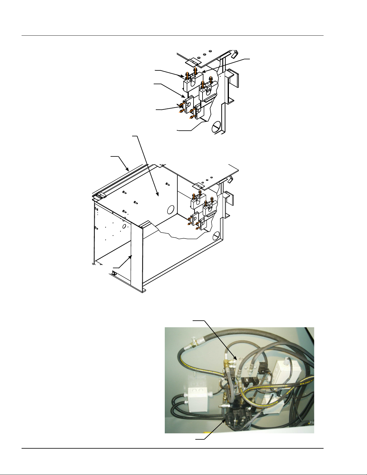
INSTALLATION
Hold-down Cylinder Trunnion
Hold-down Cylinder keepers
Pour concrete Around The
Truck Restraint Pan
Dock Leveler Pit floor
Hoist Cylinder Trunnion
Hook Cylinder Keepers
Powerhook Pan
Vertical Valve Block
KS4 Pan Inside view
Hook Valve Block
12
4111-0010 — Nov 2010

KS5 INSTALLATION
These installation instructions were written for retrofitting
a Poweramp® hydraulic dock leveler with integral power
pack with a PowerHook® KS5 Vehicle Restraint.
If you are not adding the PowerHook® to an existing
dock leveler, some steps may not be needed or
additional procedures may be required, as follows:
• When installing in new construction (i.e., new
PowerHook and new Poweramp hydraulic leveler
in a newly prepared pit), skip steps 1 through 6.
Platform modifications, step 6 were completed
prior to shipment.
• When installing PowerHook with a Poweramp
hydraulic dock leveler which is powered by remote
power pack or a CentraPower® system, refer to
the manuals provide with those units as well as to
page 15 in this manual.
• When installing Powerhook with a mechanical
dock leveler or a hydraulic dock leveler
manufactured by another company, the
PowerHook must be equipped with a remote
hydraulic power pack. See page 15 of this
manual.
INSTALLATION
Post safety warnings and barricade the work
area at dock level and ground level to prevent
unauthorized use of the dock leveler before
installation has been completed.
Failure to follow the installation instructions can
result in damage to dock leveler, the facilities, and/
or serious personal injury or death.
IMPORTANT
DO NOT connect the dock leveler electrical wiring
and ground connections until all welding has been
completed.
DO NOT ground welding equipment to any
hydraulic or electrical components of the dock
leveler. Always ground welding equipment to the
dock leveler frame, NEVER to the platform.
Failure to follow these instructions may damage the
motor, hoist cylinder, wiring, and/or control panel.
1. Review the Field Wiring Drawing and the
certified pit drawing attached to this manual. The
PowerHook KS5 vehicle restraint with a hydraulic
dock leveler requires two separate 3/4” conduit
runs from the control assembly to the junction box
located at the rear pit wall. An additional conduit,
if required, may be run either in a trench dug in
the concrete or in a space between the pit walls
and the dock leveler. The dock leveler will be
removed from the pit (steps 9-14) and reinstalled
in the pit . If additional conduit is to be imbedded
in the concrete, it may be best to do so when the
dock leveler is not in the pit. If a surface route is
planned, it may be better to install the conduit
after returning the dock leveler to the pit.
2. Raise the platform, following instructions in the
dock leveler owner’s/user’s manual, and support
with the maintenance prop.
3. Attached lifting plates, supplied by others, to the
outboard joists on both sides of the dock leveler.
Use front hole on one side and rear hole on the
other.
4. Shut off all power to dock leveler control assembly.
5. Disconnect all wires at the junction box located on
the rear pit wall.
6. Modify the underside of the dock leveler platform
as indicated on the “Dock Leveler Modification
Drawing(s)” attached to this manual.
7. Remove hydraulic fluid. To do so, locate the return
port at the drive plate for the hydraulic pump. Set a
catch vessel below the port. Remove the hose at the
return port and allow the hydraulic fluid to drain from
the reservoir. When the reservoir is empty, reinstall
the hose. Dispose of the fluid properly.
8. Use a fork truck (or other method) to raise and hold
the dock leveler platform. Remove the maintenance
prop.
9. Burn or grind all welds where the dock leveler
frame is welded to steel imbedded in the pit.
NOTE: frame removal on 10’ and 12’ long CLEAN PIT®
units may not be necessary. Consult factory.
4111-0010 — Nov 2010
13
INSTALLATION
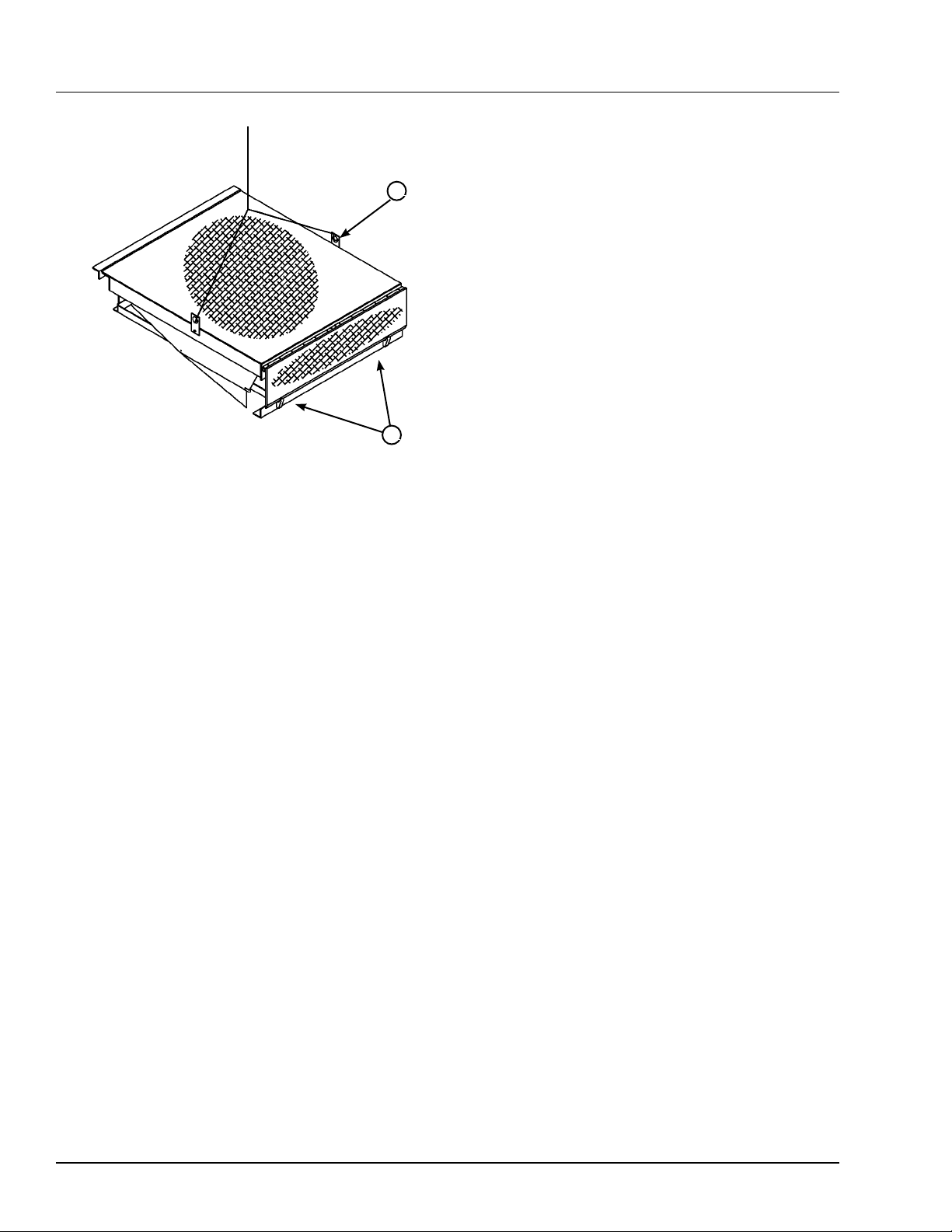
15. Cut pit for the truck restraint pan as indicated on
the Pit Drawing.
A
B
A— Lifting Bracket (2 used) B — Shipping Bands
10. This set up is only required if the dock leveler is a
CLEAN PIT® model.
A. Burn or grind off welds where the maintenance
prop and hoist cylinder trunnion box are welded
to any steel imbedded in the pit.
B. Refer to the CLEAN PIT Installation Instruction
in the dock leveler owner’s/user’s manual. The
center angle and the front angle, which were
removed during the original installation, are to
be reinstalled.
NOTE: If the angles are supplied by Systems, Inc.,
the angles are shipped with the truck restraint pan
unit.
11. Set the leveler platform in the cross traffic position
(the lip fully folded, inside the lip keepers, and the
platform level with the dock floor).
12. Place a shipping band through the lip hinge and
around the front frame angle of the leveler. Secure
the banding. The banding is to secure the frame
angle to the platform when the leveler is removed
from the pit.
13. Burn or grind all welds where the top rear frame
angle of the dock leveler is welded to the rear pit
curb angle.
16. Cut out or chip to accommodate 3/8” x 16” x 16”
hoist cylinder trunnion plates (S) which must be
imbedded into the pit floor as shown on the pit
drawing. If the existing dock leveler is a CLEAN
PIT model, it may be possible to reuse the existing
plate. On eight foot long dock levelers the plate is
an integral part of the truck restraint and a separate
plate is not required. See table on page 15
17. Install restraint pan into the pit. Insert spreader bar
into pan to reinforce during concrete pour. Make
sure the pan’s square and flush with the pit floor
and front dock wall.
18. Pour concrete around the truck restraint pan
and Hoist cylinder trunnion plates(s) that to be
imbedded in the pit floor in the plate is separate
from the pan.
19. Allow sufficient time for the concrete to set.
20. Assembly truck restraint (only required if pan was
shipped separately).
A. Remove all trunnion keepers.
B. Grease cylinder truinons.
C. Install cylinders.
D. Install all trunnion keepers and prox switches
See adjustments pg 28
21. Reinstall the dock leveler as indicated in the
dock leveler manual. Do not complete electrical
connections until all welding is complete.
22. Modify dock leveler frame as needed per “Dock
Leveler Modification Drawing”.
23. Install all hydraulic hose and fill system with
approved hydraulic oil. See page 26
24. Install outside signs and lights
25. Finish all electrical connections.
26. Adjust and test leveler and restraint operations.
14. Remove Dock leveler from the pit using the lifting
brackets.
14
4111-0010 — Nov 2010

INSTALLATION
Existing Dock Leveler Possible Cause
Length CLEAN PIT Model
6,10 or 12 Foot NO
8 Foot NO
6 Foot YES
8 Foot YES
10 or 12 Foot YES
Hoist Cylinder Trunnion Plates
Supplied by others available from Systems Inc at extra costs.
Supplied by Systems Inc (attached to KS5 pan)
* Existing plate (s) must be removed since it is partially located
in the concrete that is to be removed for the pan. Existing
plate (s) can be reused if the integrity of the plate has not
ben altered during its removal and if all the old concrete is
chipped away from the anchors.
* A new plate (s) is supplied by others or is available from
Systems Inc at extra cost.
Existing plate (s) must be removed since it is located in the
area of the concrete that is to be removed for the pan. A new
plate (s) is supplied by Systems Inc. Attached to pan). Dispose
of old, existing plate.
Existing plate (s) does not have to be removed since it is not
in the area of the concrete that is to be removed for the pan.
Existing plate (s) to be reused.
Installation Instructions for KS5 when dock leveler is
power by a Centrapower.
1. Following step 1-4 of normal retrofit instructions,
page 13.
A. Disconnect and label the hydraulic hoses
attached to the Centrapower Hydraulic valve
assembly.
B. Cap off all open fittings to prevent contamination.
2. Step 21. reinstall leveler.
3. Step 25 See VS KS4 manual on how to purge
hydraulic system.
Additional instructions for KS5 when dock leveler is
powered by a remote power pack.
1. Drain power pack.
2. Disconnect and label hydraulic hoses that are
attached to the logic block. The logic block is
attached to the underside of the dock leveler
platform.
A. Cap Off all open fittings to prevent contamination.
B. Tie off hoses to prevent damage when level is
removed. Review the Field Wiring Drawing and
the certified pit drawing attached to this manual.
3. Step 23, reconnect hoses to the logic block.
4111-0010 — Nov 2010
15

INSTALLATION
Powerhook Ks6 and Ks7 Installation instructions.
Additional installation procedures not given in this manual may be required. See the CENTRAPOWER manual for
more information.
Preparation
1. Some units are shipped with the control assembly, bumpers and outside light assembly attached to the unit.
Remove these items from unit prior to installing unit in pit. DO NOT remove the shipping bands at this time.
2. Remove all debris from the pit.
3. Check the pit dimensions with the certified pit drawing attached to this manual. Make sure that the walls of the
pit are plumb and square with no bulges. Check dock height, location of imbed plates, and J-box.
Installing unit in pit
4. Place the shims for the front and rear of the leveler on the imbed plates in the pit floor. Position the shims so
that the legs will rest firmly on the shims when the unit is lowered into the pit. Shim so that dimension from top
of shims to dock floor is as shown. Recommended shim stock sizes see Figure 8
5. Install the leveler into the pit with the lifting brackets on the side of the platform. Perform the following checks
before setting leveler into pit.
A. Make sure the front and rear legs will rest securely on the shims set on the pit floor.
B. Make sure the top rear frame angle of the dock leveler is tight against the rear curb angle and flush with
the dock floor.
C. Make sure there is equal clearance between the sides of the leveler platform and the pit walls.
6. Remove the shipping bands from the unit.
7. Use fork truck (or other method) to raise dock leveler platform.
8. Position shims under the hinge tubes of the maintenance prop so that the front panel support weldment is
level. Recommended shim stock sizes see Figure 8
Rear Imbed
Electrical J-Box
Electical J-Box
Rear Imbed
43-1/4
43-3/4
43-1/4
Imbed Plate
Shim as Required
43-3/4
16
Imbed Plate
Shim as Required
4111-0010 — Nov 2010

INSTALLATION
9. Use fork truck (or other method) to raise dock leveler platform to a height that will allow use of the maintenance
prop. The maintenance prop is accessible when the platform is raised. The top of the prop should be positioned
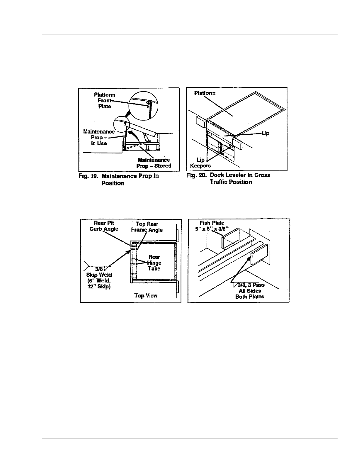
directly behind the front header plate of the platform. See Figure 4
10. Make sure that the front and rear legs are resting firmly and securely on the shims set on the pit floor. Do not
weld shims at this time.
11. Use a fork lift (or other method) to raise the leveler platform. Remove the maintenance prop. Set the platform
in the cross traffic position (lip fully folded, inside the keepers, and the platform level with the dock floor). See
Figure 5.
12. Make sure the dock leveler deck is flush with the dock floor and that the top rear frame angle of the unit is
tight against and flush with the rear pit curb angle. Raise platform install correct size shims. Check for equal
clearance between the sides of the platform and the pit walls.
13. Weld the top rear frame angle to the rear pit curb angle. Weld behind each hinge tube of the leveler platform.
See Figure 6
14. Powerhook KS6 units only: Tack weld the shims under the front legs to the legs, the plates imbedded in the
pit floor, and to the pit front curb angle. This should be done from outside the pit prior to raising platform. See
Figure 6
15. Repeat step 9.
16. Finish weld all shims to unit and, where possible, to plates or pit curb angles. Weld shims together where
stacked
17. Refer to Figure 8.
A. On levelers with single hoist cylinder, shim the hoist cylinder support so that the center channels are level.
Weld shims in place.
B. On levelers with dual hoist cylinders, shim under the cylinder supports so that the side channels are level.
In addition, shim under the center beam support so that the center beam is level. Weld all shims in place.
18. Weld fish plates to the center channels of the leveler and to the plate imbedded in the rear pit wall. refer for
recommended fish plate sizes and location. Figure 7
19. Clean and paint all welds
20. Weld and/or bolt bumpers in place on face of dock. Refer to certified Pit Drawing.
21. If leveler is part of a Centrapower system or if the power pack is located remotely, connect the hydraulic hoses
to the dock leveler as indicated in the Centrapower manual instructions
22. Check the hydraulic fluid level. Standard units are shipped with the reservoir full. However, fluid level should
be checked before operation unit for the first time to make sure no fluid loss occurred during shipment or
installation. See the Preventative Maintenance Section.
Note: For Centrapower or remote power pack units, see appropriate instructions
23. If the electrical installation is to be preformed at a later date, use a fork lift to set the unit in the cross traffic
position (lip fully folded, inside the lip keepers and the platform level with the floor).
4111-0010 — Nov 2010
17

INSTALLATION
18
Figure 8
4111-0010 — Nov 2010
INSTALLATION
Figure 4
Figure 6
Figure 5
Figure 7
4111-0010 — Nov 2010
19

INSTALLATION
8”
Allow enough
clearance for
possible seal
or shelter.
11 3/8
16-7/8
Optional
Guide Lights
96”
Drive
KS6 Dock Leveler
20
4111-0010 — Nov 2010

Operating Instructions
OPERATION
Stay clear of dock leveler when freight carrier is
entering or leaving dock area.
DO NOT move or use the dock leveler if anyone is
under or in front of leveler.
Keep hands and feet clear of pinch points. Avoid
putting any part of your body near moving parts.
Failure to follow these instructions may result in
severe personal injury or death.
Only trained personnel should operate the dock
leveler and truck restraint.
DO NOT use a broken or damaged dock leveler
or truck restraint. Make sure proper service and
maintenance procedures have been performed on
equipment before using.
Truck/trailer wheels must be chocked unless the
truck restraint is used. Never remove the wheel
chocks until loading/unloading is finished and truck
driver has been given permission to leave.
DO NOT overload the dock leveler.
DO NOT operate any equipment while under the
influence of alcohol or drugs.
DO NOT leave equipment or material unattended on
the dock leveler.
Failure to follow these instructions may result in
personal injury and/or damage to equipment.
Make sure platform lip rests on the truck/trailer bed
with at least 4 in. (102 mm) of overlap.
Maintain a safe distance from side edges of leveler
during the loading/unloading process.
Failure to follow these instructions may result in
serious personal injury or death.
4111-0010 — Nov 2010
21

OPERATION
SEQUENCE OF OPERATION - NORMAL SEQUENCE OF OPERATION - BYPASS
1. Check that the truck/trailer is positioned squarely
against the dock bumpers.
- Inside Red Light
-Outside Green Light
2. Push ENGAGE button to activate restraint.
- Inside Red Light
-Outside Green Light
3. Visually inspect restraint for proper engagement.
If RIG (Rear Impact Guard) is damaged or
missing, dock leveler can be used in BYPASS
IF BYPASS MODE IS REQUIRED
SEE: SEQUENCE OF OPERATION - BYPASS
FOR NORMAL OPERATION AFTER TRAILER
RIG IS ENGAGED CONTINUE WITH: STEP 4
4. Position dock leveler onto truck/trailer.
5. When loading or unloading is complete, return dock
leveler to the stored position.
1. Check that the truck/trailer is positioned squarely
against the dock bumpers.
2. Push ENGAGE button to activate restraint.
- Inside Red Light
-Outside Green Light
3. Visually inspect restraint for proper engagement.
If RIG (Rear Impact Guard) is damaged or missing
dock leveler can be used in BYPASS.
4. If RIG (Rear Impact Guard) is damaged or missing,
hook will automatically return to the stored position.
-Inside Amber Light for 30 seconds, then Red
-Outside Red Light for 30 seconds, then Green
5. Secure truck/trailer wheels with wheel chocks.
6. Use key to activate BYPASS mode.
-Inside Green Light with Amber Caution Light
-Outside Red Light and Strobe
7. Position dock leveler onto truck/trailer
6. Release truck restraint and/or remove chocks from
truck/trailer wheels.
8. When loading or unloading is complete, return
dock leveler to the stored position.
-Inside Green Light with Amber Caution Light
-Outside Red Light
9. Reset BYPASS mode to NORMAL mode by
pressing the LOCK button once.
-Inside Red Light, Amber turns Off
-Outside Green Light
-Pressing the LOCK button during any part of the
cycle will end the BYPASS mode
-Pressing the LOCK button a second time will
cycle the PowerHook.
10. Remove wheel chocks from the truck/trailer wheels
when truck is ready to depart.
22
4111-0010 — Nov 2010

MAINTENANCE
Service Dock Leveler/Restraint Safely
F
E
C
D
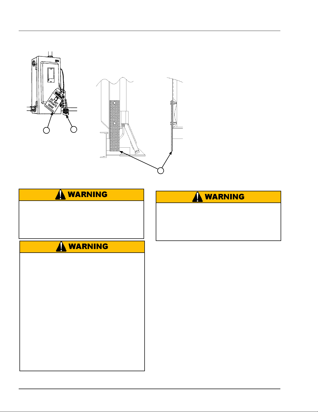
A— Tag out Device B — Lockout Device C — Lockout Device D — Tag out Device E — Maintenance Prop F — Header Plate
When service under the dock leveler is required,
always lock all electrical disconnects in the OFF
position after raising the platform and engaging the
maintenance prop. Failure to do this may result in
serious personal injury or death.
Always stand clear of the dock leveler lip when
working in front of the dock leveler.
The maintenance prop MUST be in the service
position when working under the dock leveler.
For maximum protection, use an OSHA approved
locking device to lock the maintenance prop in
the service position. Only the person servicing
the equipment should have the key to unlock the
maintenance prop.
Unless the dock leveler is equipped with a tethered
remote, two people are required to engage the
maintenance prop: one person to operate the unit,
the other person to engage the maintenance prop.
Failure to follow these instructions may result in
serious personal injury or death.
Always post safety warnings and barricade the
work area at dock level and ground level to prevent
unauthorized use of the dock leveler before
maintenance is complete. Failure to do this may
result in serious personal injury or death.
Whenever maintenance is to be performed under
the dock leveler platform, support the platform with
maintenance prop (E). Position the maintenance prop
behind front header plate (F) while staying clear of the
lip. The lip will fold down after the platform has rested
on the maintenance prop. Lock the maintenance
prop in the service (upright) position using an OSHA
approved lockout device* (C) and Tag out device* (D).
Whenever servicing the dock leveler, lock the electrical
power disconnect in the OFF position. Use only an
OSHA approved lockout device* (B) and Tag out
device (A).
Only the person servicing the equipment should have
the capability to remove the lockout devices. The Tag
out devices* must inform that repairs are in process
and clearly state who is responsible for the lockout
condition.
* Refer to OSHA regulation 1910.147.
4111-0010 — Nov 2010
23
MAINTENANCE
Service Dock Leveler/Restraint Safely
A
When service under the dock leveler is required,
always lock all electrical disconnects in the OFF
position after raising the platform and engaging the
maintenance prop. Failure to do this may result in
serious personal injury or death.
Always stand clear of the dock leveler lip when
working in front of the dock leveler.
The maintenance prop MUST be in the service
position when working under the dock leveler.
For maximum protection, use an OSHA approved
locking device to lock the maintenance prop in
the service position. Only the person servicing
the equipment should have the key to unlock the
maintenance prop.
Unless the dock leveler is equipped with a tethered
remote, two people are required to engage the
maintenance prop: one person to operate the unit,
the other person to engage the maintenance prop.
Failure to follow these instructions may result in
serious personal injury or death.
B
C
Always post safety warnings and barricade the
work area at dock level and ground level to prevent
unauthorized use of the dock leveler before
maintenance is complete. Failure to do this may
result in serious personal injury or death.
When maintenance is to be performed on the dock
leveler, First install the SAFETY bolt in the storage
prop. Second support the platform with maintenance
props (D). Caution: The lip may will fold down after
the platform has rested on the maintenance prop.
Whenever servicing the dock leveler, lock the electrical
power disconnect in the OFF position. Use only an
OSHA approved lockout device* (B) and tagout device
(A).
Only the person servicing the equipment should have
the capability to remove the lockout devices. The
tagout devices* must inform that repairs are in process
and clearly state who is responsible for the lockout
condition.
* Refer to OSHA regulation 1910.147.
24
4111-0010 — Nov 2010

Daily Maintenance
• Make sure that all the Inside and Outside signal
lights work.
Weekly Maintenance
• Operate the dock leveler and PowerHook through the
complete operating cycle to maintain lubrication.
Quarterly Maintenance
• Lubricate the following areas with white lithium
grease:
(A)— Hook cylinder trunnions
(B) — Position cylinder trunnions.
(C) — Inspect Prox harness.
(D) — Inspect Hoses.
Yearly Maintenance
• Lubricate the following areas with white lithium
grease:
(A)— Hook cylinder trunnions
(B) — Position cylinder trunnions.
(C) — Inspect Prox harness
(D) — Inpesct Hoses.
(E) — Change Hydraulic Oil (May be required
earlier depending on conditions).
MAINTENANCE
IMPORTANT
A low fluid level or the use of hydraulic fluids not
equivalent to the fluid types recommended, will
cause abnormal operation of the leveler and WILL
void warranty.
P
N
M
M — Reservoir
N — 2 in. (51 mm) (From Top of
Reservoir)
Q
P — Breather Cap
Q — Fluid Level
IMPORTANT
Failure to properly lubricate the Truck Restraint will
cause abnormal operation.
KS4 Pan Wldt for
Manual
C
A
B
D
4111-0010 — Nov 2010
25

MAINTENANCE
P
N
Q
KS5 or KS6 and KS7
• Check reservoir fluid level (Q):
1. Put the dock leveler platform at the full
below-dock position.
2. Turn OFF all electrical power to the leveler.
M
M — Reservoir
N — 2 in. (51 mm) (From Top of
Reservoir)
P — Breather Cap
Q — Fluid Level
KS4 Only
• Check reservoir fluid level (Q):
1. Put the leveler in the stored position Lip folded.
2. Turn OFF all electrical power to the leveler.
3. Remove inspection plate.
4. Remove breather cap (P).
5. Measure fluid level. The fluid level should be
approximately 2 in. (51 mm) (N) from top of
reservoir.
6. Add hydraulic fluid if necessary. Use only
recommended fluid.
7. Install breather cap and inspection plate.
8. Turn ON electrical power to the leveler.
9. Return the platform to the cross-traffic position.
IMPORTANT
Use of fluids that do not have equivalent
specifications to those in the following list will result
in abnormal operation of the dock leveler and
voiding of warranty.
3. Remove breather cap (P).
4. Measure fluid level. The fluid level should be
approximately 2 in. (51 mm) (N) from top of
reservoir (M).
5. Add hydraulic fluid if necessary. Use only
recommended fluid.
6. Install breather cap.
7. Turn ON electrical power to the leveler.
26
To ensure normal operation of the truck restraint, use
only aircraft hydraulic fluid designed to meet or exceed
military specification MIL-L-5606. It is recommended
that the following hydraulic fluids be used:
• Flomite 530 ZF
• Ultra-Vis HV1-15
• Aero Shell Fluid 4 or Fluid 41
• Mobil Aero HFA Mil-HS606A or Aero HF
• Texaco Aircraft Hydraulic Oil 15 or 5606
• Exxon Univis J13
These fluid brands can be mixed together. Mixing with
fluids that do not meet or exceed MIL-L-5606 may
damage the equipment and WILL void warranty. Use
of hydraulic fluids with equivalent specifications to
those listed here are acceptable.
4111-0010 — Nov 2010

Testing PowerHook Operating Range
When service under the dock leveler is required,
always lock all electrical disconnects in the OFF
position after raising the platform and engaging the
maintenance prop. Failure to do this may result in
serious personal injury or death.
Always post safety warnings and barricade the
work area at dock level and ground level to prevent
unauthorized use of the dock leveler before
maintenance is complete. Failure to do this may
result in serious personal injury or death.
ADJUSTMENT AND TESTING
NOTE: Test operating range of PowerHook without
truck/trailer backed into dock.
1. Position the selector switch in the Normal position,
make sure BYPASS mode has not been activated.
-Red Inside Light, No Amber Light
-Green Outside Light
2. Momentarily press the ENGAGE button. Hook
should lower, fully extend, fully raise, partially
retract, lower, and then fully retract.
-Inside Amber Light for 30 seconds, then Red
*Alarm will sound if equipped
-Outside Red Light for 30 seconds, then Green
3. Measure upper and lower limits of operating
range. The upper and lower limits of the
vertical operating range should be 26”-28”
and 8”-9” respectively (Application Dependent).
Always stand clear of the dock leveler lip when
working in front of the dock leveler.
The maintenance prop MUST be in the service
position when working under the dock leveler.
For maximum protection, use an OSHA approved
locking device to lock the maintenance prop in
the service position. Only the person servicing
the equipment should have the key to unlock the
maintenance prop.
Unless the dock leveler is equipped with a tethered
remote, two people are required to engage the
maintenance prop: one person to operate the unit,
the other person to engage the maintenance prop.
Failure to follow these instructions may result in
serious personal injury or death.
Follow the installation instructions found in the
PowerHook Installation & Operation Manual prior
to attempting any adjustments.
With the PowerHook installed in the hook pan
and power supplied to the pump/motor, proceed
with the PowerHook adjustments.
Hook In Highest
Position
Hook Must
Clear pit
Floor While
Extending
26”-28”
8”-9”
Drive
Hook In Lowest
Position
Store
Alarm
Lower Limit
Extended
Upper Limit
Extended
NOTE: Hook cannot be stopped while cycling. To
obtain measurements place tape measure next to the
moving hook.
IMPORTANT: The upper and lower limits of the
operating range will vary with application pit depth.
These limits may not be attainable if variations in dock
height and/or pit depth exist. Consult factory if this
situation occurs.
4111-0010 — Nov 2010
27

ADJUSTMENTS
Adjust PowerHook Operating Range
Hook Cylinder
Threaded Eye
and Jam Nut
Counter clock Wise
Clock Wise
Hose Port
Hook cylinder trunnions
Position cylinder trunnions
Figure 10
1. Adjust the upper vertical limit of PowerHook
operating range if necessary.
A. Locate the hook cylinder assembly and the
hold down cylinder assembly. The length of
the threaded eye on the hold down cylinder will
determine the upper vertical limit of the hook
movement.
B. Disconnect the Hydraulic hose from the hold
down cylinder. Cap off the open fittings to
prevent fluid loss and to prevent contamination
from entering the system.
C. Remove the keepers from the hold down
cylinder trunnion.
D. Lift up on the hook cylinder. This will allow the
hold down cylinder to exit the trunnion.
E. Support hook cylinder, loosen the jam nut
that is on the threaded eye of the hold down
cylinder.
Figure 11
28
4111-0010 — Nov 2010

Adjust PowerHook Operating Range
ADJUSTMENTS
1. Adjust the lower vertical limit of hook operating
range if necessary.
A. Locate the proximity switch that is mounted in
the bracket located on the trunnion for the hook
cylinder. Locate the target for the switch. See
Figure 12.
NOTE: The position of the target in relation to the
switch will determine the lower travel limit of the hook.
When the hook lowers, the target is positioned into
the sensing area of the proximity switch. The switch
is activated when the target is sensed, at which time
Input 3 on the PLC should be ON.
At no time should the target come into direct contact
with the switch.
The typical factory set position for the target is at the
10 o’clock position looking at it from the side with the
hook lowered sensor at 12 o’clock.
See Figure 13
B. Loosen the bolt that holds the target.
C. Lower Hook: Turn the target 2-4 degrees
counterclockwise if top of the hook is greater
than 9”.
D. Raise Hook: Turn the target 2-4 degrees
clockwise if the top of the hook is less than 8”.
E. Repeat Steps C or D until the lower vertical
limit of the top of hook is 8”-9” above the apron.
When adjustments are completed hold the
target in place and tighten the bolt.
B
A
A— Hook Lowered Sensor
Target Bar
B—Powerhook Hold Down
Weldment
Figure 12
C— Hook Lowered Sensor
Bracket
D—Flat Washer
E— Trunnion Bolt
C
E
D
4. Check lights.
-Inside Green
-Outside Red
5. Test dock leveler operation. See dock leveler
Owner’s Manual.
6. Checking of Alarm (if equipped) and Lights for
Premature Truck Departure can be accomplished
by having a truck attempt to pull away from an
engaged hook. It is not recommended due to
potential damage to RIG bars that may not be up
to current strength standards.
2. Test with truck/trailer or a ICC bar simulator. (The
simulator must span min of 6” past both sides of
pan)
3. Press the ENGAGE button. Truck restraint hook
should lower, extend, raise, and retract until it locks
onto the ICC bar. Power pack should then shut off.
4111-0010 — Nov 2010
7. Press RELEASE button. The PowerHook should
disengage from the RIG bar and restore behind
the dock wall. Power pack should then shut off.
8. Check Lights
-Inside Light Red
-Outside Light Green
29

ADJUSTMENTS
#3 prox switch
Start
adjustments
at 10o’clock
position
Figure 13
Powerhook Pressure relief Adjustment.
The pressure relief on a Powerhook is not adjusted by
the relief mounted on the pump. The pressure relief is
regulated by the relief mounted on the Big block.
On KS6 and KS7 restraints the relief is preset from the
factory and normally is not touched. KS4 and KS5 truck
restraints of some SC hooks the relief must be adjusted
during installation.
Locate the hook cylinder assembly and the hold down
cylinder assembly. See Figure 10. The length of the
threaded eye on the hold down cylinder will determine
the upper vertical limit of the hook movement.
C. Loosen lock nut and turn valve RV counter
clockwise until the valve stops.
E.Press the engage button the motor will run
but the hook will not move. Turn the RV
valve clockwise until the hook lowers to 2” off
the bottom of the pan then add one full turn
clockwise and lock in place. If the PLC shuts
down the motor before adjustments have been
reset the and continue were PLC shut off.
F.Re install wire (36) for input #3 on the PLC.
G.Test hook for proper operation.
A. Raise Leveler on to the maintenance prop and
lock in place.
B. Remove wire (36) from input #3 on the PLC.
30
4111-0010 — Nov 2010
OPTIONAL EQUIPMENT ADJUSTMENTS
Adjust Dock Leveler and Truck Restraint Interlock
Dock Leveler and Truck restraint Interlock
The dock leveler can be interlocked with the truck
When service under the dock leveler is required,
always lock all electrical disconnects in the OFF
position after raising the platform and engaging the
maintenance prop. Failure to do this may result in
serious personal injury or death.
Always post safety warnings and barricade the
work area at dock level and ground level to prevent
unauthorized use of the dock leveler before
maintenance is complete. Failure to do this may
result in serious personal injury or death.
Always stand clear of the dock leveler lip when
working in front of the dock leveler.
The maintenance prop MUST be in the service
position when working under the dock leveler.
For maximum protection, use an OSHA approved
locking device to lock the maintenance prop in
the service position. Only the person servicing
the equipment should have the key to unlock the
maintenance prop.
restraint so that the leveler cannot be operated until
the restraint has engaged the truck/trailer RIG (Rear
Impact Guard) when the OPERATION switch is in
NORMAL and has NOT been switched to BYPASS.
The truck restraint is interlocked with the dock leveler
so that the restraint cannot be operated until the
leveler is stored in the cross traffic position (lip fully
folded, inside the keepers, and the platform level with
the dock floor).
Leveler and restraint interlocking are overridden when
the OPERATION switch is in BYPASS. Thie allows
the independent operation of the leveler (the restraint
cannot be operated in BYPASS).
Pressing the restraint ENGAGE button when in
BYPASS mode will return the leveler to NORMAL
operating mode.
This option is not available on units equipped with the
Auto Return to Dock option.
Unless the dock leveler is equipped with a tethered
remote, two people are required to engage the
maintenance prop: one person to operate the unit,
the other person to engage the maintenance prop.
Failure to follow these instructions may result in
serious personal injury or death.
With the PowerHook installed in the hook pan and
power supplied to the pump/motor, proceed with the
PowerHook adjustments.
Note: Test operating range of PowerHook without
truck/trailer backed into dock.
4111-0010 — Nov 2010
When service under the dock leveler is required with
power on. The platform must be on the maintenance
prop and locked out. The are must be marked with
safety cones and sighs Failure to do this may result
in serious personal injury or death.
31

OPTIONAL EQUIPMENT ADJUSTMENTS
Adjust & Test Dock Leveler and Truck Restraint Interlock
B
A
C
E
D
Figure 37
A— 1/4 in. (6.4 mm)
Approximate
B— Target
C— 1 in. (25.4 mm)
Approximate
D— Lock Nuts
E— Proximity Switch
1. The dock leveler should be in the cross traffic
position (stored in the lip keepers) before
beginning tests.
2. Back a truck/trailer with RIG bar into dock. A test
fixture may be used to simulate the RIG bar. Use
care to avoid damage to the equipment or harm
to the operator.
3. Press the RAISE push button. The dock leveler
should NOT raise. If the leveler did not raise,
proceed with step 4. If the leveler did raise,
decrease dimension “A” or “B”, Figure 37, so
that the target is in the sensing range of the
switch. Typical factory settings for “A” and “B” are
approximately 3/4” and 1/8” respectively. Make
adjustments at switch (dimension B) and/or target
(dimension A) until leveler does not raise when
the truck restraint is not engaged at truck trailer
RIG bar.
4. Momentarily press the ENGAGE button. The truck
restraint will be activated and the restraint will
engage the truck/trailer RIG bar.
B
B
A
E
D
Figure 38
A— 3/16 in. (6.4 mm)
Approximate
B— Target
C— 1 in. (25.4 mm)
Approximate
D— Lock Nuts
E— Proximity Switch
6. Press the RELEASE button. The truck restraint
should NOT disengage from the truck/trailer
RIG bar or test fixture. If the restraint did NOT
engage, proceed with step 7. If the restraint DID
disengage, move the switch farther from the
target or bend the target so that the target is not
in the sensing range of the switch as shown in
Figure 38. Make adjustments at switch and/or
target until restraint does not disengage truck/
trailer.
IMPORTANT: If adjustments are required in this
step, make sure that the interlocking described
in step 3 is still in effect after step 6 adjustments
are complete.
7. Press the RAISE push button. The dock leveler
will raise. The leveler lip will fold as the platform
raises. When the lip is fully folded, release the
RAISE push button. The leveler will descend to
the cross traffic position.
8. Momentarily press the RELEASE button. The
truck restraint will return to the stored position.
5. Raise the dock by pressing the RAISE button
until the lip is fully extended. Release the RAISE
button. The leveler will drop to the floor of the
truck/trailer. If a RIG test fixture is used it should
allow the leveler to drop to the full below dock
position without the contact between the lip and
test fixture.
32
4111-0010 — Nov 2010
4111-0010 — Nov 2010

OPTIONAL EQUIPMENT ADJUSTMENTS
Adjust Auto Return To Dock (ARTD)
E
D
C
B
A
H
A— Cable
B— Proximity Switch
C— Bracket
D— Lock Nuts
E— Target
F— Lip Hinge Tube
G—Platform Lip
H— Indicator Light
Standard leveler with Powerhooks are equipped with
Interlock unless leveler has option of Auto Return To
Dock (ARTD).
The ARTD allows the platform to automatically return
to the cross-traffic (stored) position after the truck
departs. The ARTD uses a proximity switch (B) located
under the platform and a piece of angled steel called
the target (E) that is attached to the lip hinge tube (F).
F
G
Adjust the ARTD as Follows:
1. Raise platform fully and engage the maintenance
prop in the service position. Allow platform to rest
on the prop so the lip will fully fold until it contacts
the lip stops.
2. Turn OFF all electrical power to the dock leveler.
Attach safety lockout and tag-out devices.
When service under the dock leveler is required with
power on. The platform must be on the maintenance
prop and locked out. The are must be marked with
safety cones and sighs Failure to do this may result
in serious personal injury or death.
Always post safety warnings and barricade the
work area at dock level and ground level to prevent
unauthorized use of the dock leveler before
maintenance is complete. Failure to do this may
result in serious personal injury or death.
The PLC provides a six-second delay after the
platform has lowered to the full below-dock position,
after which, the platform will return to the cross-traffic
position. The switch also contains an indicator light
(H) that can be used for diagnosing and adjusting the
switch.
NOTE: The proximity switches has an indicator light
at the back of the housing and some have the
light at the side of the housing.
When service under the dock leveler is required,
always lock all electrical disconnects in the OFF
position after raising the platform and engaging the
maintenance prop. Failure to do this may result in
serious personal injury or death.
Always stand clear of the dock leveler lip when
working in front of the dock leveler.
The maintenance prop MUST be in the service
position when working under the dock leveler.
For maximum protection, use an OSHA approved
locking device to lock the maintenance prop in
the service position. Only the person servicing
the equipment should have the key to unlock the
maintenance prop.
Unless the dock leveler is equipped with a tethered
remote, two people are required to engage the
maintenance prop: one person to operate the unit,
the other person to engage the maintenance prop.
Failure to follow these instructions may result in
serious personal injury or death.
4111-0010 — Nov 2010
33

OPTIONAL EQUIPMENT ADJUSTMENTS
ARTD Continued
IMPORTANT
Anytime proximity switch and target are adjusted,
always check for interference between target and
switch before operating the leveler. Damage to
switch will occur if the target contacts the switch.
The maximum torque for proximity switch lock nuts
is 27 N•m (29 lb-ft). Damage to switch will occur if
maximum torque is exceeded.
B
A
C
E
D
6. Turn ON electrical power to the dock leveler.
7. Disengage the maintenance prop.
8. Turn the ARTD switch (on control panel) to the ON
position.
9. Raise the platform until the lip is fully extended,
then allow the platform to drift to the below-dock
position.
10. After approximately 6 seconds, the platform will
return to the cross-traffic position.
11. Adjust the proximity switch and target as
necessary. Make small adjustments, then operate
the dock leveler to check results. Do this until
satisfied with the ARTD operation.
12. Use the following illustrations to assist in fine
tuning and/or diagnosing the ARTD operation.
Cross-Traffic Position
A— 1/4 in. (6.4 mm)
Approximate
B— Target
C— 1 in. (25.4 mm)
Approximate
D— Lock Nuts
E— Proximity Switch
NOTE: Distances (A and C) are typical factory
settings. Use these dimensions only as a starting
point when adjusting the proximity switch and
target, especially if switch and/or target have been
replaced.
When dimensions (A and C) are obtained,
the proximity switch and target may need
finer adjustments to get the ARTD to operate
satisfactorily.
3. Loosen lock nuts (D). Adjust proximity switch (E) to
obtain distance (A). Tighten lock nuts.
4. Bend target (B) as needed to obtain distance (C).
Recheck distance (A) and readjust if necessary.
NOTE: At least two people may be required to
manually move the lip.
5. After adjusting proximity switch and target, slowly
move the lip up by hand while observing the
target and proximity switch. The target MUST
NOT contact the switch, otherwise, damage to
switch will occur. Readjust switch and/or target if
necessary, then recheck for interference.
Lip Keeper
NOTE: The platform lip is fully folded when the
platform is at the cross-traffic (stored) position (lip
engaged with keepers) or when platform is resting
on the maintenance prop.
Whenever the platform lip is at the cross-traffic
position, the following conditions will exist for a
normally operating ARTD:
• Target not in the sensing area of proximity switch.
• Proximity switch OFF (open) (no signal sent to
control panel).
• Proximity switch indicator light is OFF.
• Platform stays at this position unless the operator
activates the leveler.
34
4111-0010 — Nov 2010

OPTIONAL EQUIPMENT ADJUSTMENTS
Full Below-Dock Position
Lip Keeper
Whenever the platform lip is at the full below-dock
position, the following conditions will exist for a
normally operating ARTD:
• Proximity switch senses target.
• Proximity switch ON (closed) (signal sent to the
control panel).
• Proximity switch indicator light is ON.
• Platform will automatically rise after approximately a
six-second delay, then returns to the cross-traffic
position.
Lip Fully Extended Position
Whenever the platform lip is at the fully extended
position, the following conditions will exist for a
normally operating ARTD:
• Target not in the sensing area of proximity switch.
• Proximity switch OFF (open) (no signal sent to the
control panel).
• Proximity switch indicator light is OFF.
• If the platform lip is resting on the truck bed, the
platform will stay at this position unless the
operator activates the leveler.
4111-0010 — Nov 2010
35

TROUBLESHOOTING POWERHOOK
When service under the dock leveler is required,
always lock all electrical disconnects in the OFF
position after raising the platform and engaging the
maintenance prop. Failure to do this may result in
serious personal injury or death.
Always post safety warnings and barricade the
work area at dock level and ground level to prevent
unauthorized use of the dock leveler before
maintenance is complete. Failure to do this may
result in serious personal injury or death.
Before performing the detailed troubleshooting procedures, check the following items first:
• Check all fuses inside the control panel(s). Replace
any blown fuse(s) with a fuse of equal specification.
Always stand clear of the dock leveler lip when
working in front of the dock leveler.
The maintenance prop MUST be in the service
position when working under the dock leveler.
For maximum protection, use an OSHA approved
locking device to lock the maintenance prop in
the service position. Only the person servicing
the equipment should have the key to unlock the
maintenance prop.
Unless the dock leveler is equipped with a tethered
remote, two people are required to engage the
maintenance prop: one person to operate the unit,
the other person to engage the maintenance prop.
Failure to follow these instructions may result in
serious personal injury or death.
• Make sure the correct voltages are present at the
proper locations inside the control panel(s).
Symptom Possible Cause Solution
Inside and outside signal
lights do not operate.
Controller (PLC)
RUN indicator is on
solid (not flashing). Unit
operates as normal.
Restraint does not
operate. Motor does not
energize.
Bad Flasher. Replace flasher with wire. If lights operate (lights will
not flash), replace flasher.
Motor overload device
tripped.
Motor starter (3 phase) or
motor relay (1 phase) not
energizing.
Reset overload relay (3 phase) or replace fuse (1
phase) or reset breaker (1 phase-new models).
Determine cause of device tripping.
NOTE: If replacing fuse, use fuse with equal specification .
Check controller output that sends a signal to starter
or relay. Output may have failed OPEN. Use meter
to check for contact closure when output ON.
36
4111-0010 — Nov 2010

TROUBLESHOOTING POWERHOOK
Symptom Possible Cause Solution
Three-phase units only:
Restraint does not
operate. Motor energizes
but does not run.
If motor hums, but does
not run, overload device
should trip.
Three-phase units only:
Restraint does not
operate. Motor runs in
reverse
Single-phase units only:
Restraint does not
operate.
Motor energizes, but
does not run.
3 Phase units only - no
voltage is present on one
line.
NOTE: A motor that is
missing voltage on one line
is said to be single-phased.
Check for blown fuses at branch circuit disconnect.
Replace fuse. Determine cause of blown fuse.
Check motor starter as follows:
1. Disconnect wires at load side of starter.
2. Energize the starter.
3. Measure line-to-line voltage at line side of starter.
4. Measure line-to-line voltage at load side of
starter.
5. Line-side and load-side voltages should be
approximately the same. Replace starter if
voltage values are considerably different from
one another.
Check all wiring to motor for high resistance or no
connection.
Replace motor.
Phase reversed. Reverse any two legs at the branch circuit
disconnect.
Line voltage too low. Check wiring to motor for high resistance. Check for
loose or corroded connections. Check wire gauge for
correct size and specification for load requirement.
Replace if necessary.
Defective motor centrifugal
Replace motor.
switch.
Restraint operates
slowly.
Defective motor capacitor. Replace motor.
Low hydraulic fluid. Add fluid, see Maintenance section for proper fluid
level and type.
Pressure relief valve set too
low.
Locate valve on main valve block (labeled RV).
Turn the valve all the way counter-clockwise. While
operating the restraint, slowly turn the valve in
clockwise, until the restraint lowers and begins
to extend. Turn valve in an additional 1.2 turn
clockwise.
NOTE: The pressure relief valve must not be set at a
level that causes the motor operating current
to exceed the full load amp value* at any time,
including when operating in pressure relief.
* The full load amp value can be found on the inside cover of the
control panel.
Damage or blocked
hydraulic hose(s) and/or
Replace damaged hose(s). Check and remove
blockage from hose(s) and/or valve(s).
valve(s).
4111-0010 — Nov 2010
37

TROUBLESHOOTING POWERHOOK
Symptom Possible Cause Solution
Restraint does not
fully extend or motor
overcurrent device and/
or overload device
continuously tripping.
Restraint lowers, fully
extends but does not
raise. Pump operates in
pressure relief.
Low hydraulic fluid. Add fluid, see Maintenance section for proper fluid
level and type.
Solenoid “D” valve stuck
ON.
Proximity switch on guide
track that senses when
restraint is fully extended is
out of adjustment.
Locate solenoid (See Parts: Valve Block).
Remove coil from cartridge valve and cartridge valve
from valve block.
-Check valve for contaminant’s and/or damage.
-Replace valve if damaged.
-Carefully wipe valve with clean rag (do not damage
“O” rings on valve).
-Check valve block for contaminant’s.
-Replace valve and coil.
NOTE: Do not over tighten valve into block. Max Torque:
30-40 lb/ft. or snug to prevent leakage. Tighten coil snug,
avoid over tightening and causing valve to bind.
Operate unit. Replace valve if problem persists and
all other troubleshooting procedures performed.
Locate switch on end of guide track closest to hook
tip. Observe indicator light at controller input (#4)
that receives signal from switch. Input light should
turn OFF when restraint fully extended. If this does
not occur:
-Check switch position, loosen two guide track
mounting bolts, tap guide track assembly back
towards rear pit wall.
-Switch should be positioned approximately 1/4”
from the inside wall of the track. Make sure that the
switch face does not extend further than the guide
track mounting bars welded to the cylinder. Position
switch so that face will not come into contact with
guide rod.
-Tighten nuts to secure switch. DO NOT over tighten
nuts. Maximum tightening torque is 25 lb/ft.
-Run restraint. Make sure motor shuts off when
hook is in stored position. If motor does not shut
off, reposition guide track slightly forward of current
position.
38
4111-0010 — Nov 2010

TROUBLESHOOTING POWERHOOK
Symptom Possible Cause Solution
Restraint extends from
stored position without
fully lowering.
Restraint extends from
stored position without
lowering at all.
Proximity switch at trunnion
that senses when restraint
lowered target out of
adjustment.
Proximity switch at trunnion
that senses when restraint
lowered target out of
adjustment.
Solenoid “B” valve stuck
OFF.
Locate switch on hook trunnion. Observe indicator
light at controller input (#3) that receives signal
from switch. Input light should only turn ON when
restraint fully lowered. If this does not occur, adjust
target counterclockwise. See Adjustments section:
Adjust PowerHook Operating Range.
Use a screwdriver as a temporary target to test
switch. Replace switch if screwdriver is present and
input light on controller does not turn on.
Locate switch on hook trunnion. Observe indicator
light at controller input (#3) that receives signal from
switch. Input light should only turn ON when restraint
fully lowered. If this does not occur, adjust target
counterclockwise. See Adjustments section: Adjust
PowerHook Operating Range.
Use a screwdriver as a temporary target to test
switch. Replace switch if screwdriver is present and
input light on controller does not turn on.
Locate solenoid (See Parts: Valve Block).
Remove coil from cartridge valve and cartridge valve
from valve block.
Solenoid “B” coil is not
receiving signal to energize.
A solenoid that is energized
will act like a magnet.
Place a metal tool on coil of
solenoid to determine if coil
is receiving signal.
Solenoid “B” coil receiving
signal but not energizing.
-Check valve for contaminant’s and/or damage.
-Replace valve if damaged.
Carefully wipe valve with clean rag (do not damage
“O” rings on valve.
-Check valve block for contaminant’s.
-Replace valve and coil.
NOTE: Do not over tighten valve into block. Max Torque:
30-40 lb/ft. or snug to prevent leakage. Tighten coil snug,
avoid over tightening and causing valve to bind.
Operate unit. Replace valve if problem persists and
all other troubleshooting procedures performed.
1. Check controller output that sends a signal to
solenoid. Output may have failed OPEN. Use
meter to check for contact closure when output
is ON.
2. Check all wiring to solenoid for high resistance
(loose) or no connection.
Coil failed OPEN. Consult Factory for replacement
part.
4111-0010 — Nov 2010
39

TROUBLESHOOTING POWERHOOK
Symptom Possible Cause Solution
Restraint does not
lower at all from
stored position. Pump
operates in pressure
relief (restraint does not
extend).
Solenoid “D” valve stuck off. Locate solenoid (See Parts: Valve Block).
Remove coil from cartridge valve and cartridge valve
from valve block.
-Check valve for contaminant’s and/or damage.
-Replace valve if damaged.
-Carefully wipe valve with clean rag (do not damage
“O” rings on valve).
-Check valve block for contaminant’s.
-Replace valve and coil.
NOTE: Do not over tighten valve into block. Max Torque:
30-40 lb/ft. or snug to prevent leakage. Tighten coil snug,
avoid over tightening and causing valve to bind.
Operate unit. Replace valve if problem persists and
all other troubleshooting procedures performed.
Solenoid “D” coil not
receiving signal to energize.
A solenoid that is energized
will act like a magnet.
Place a metal tool on coil of
solenoid valve to determine
if coil is receiving signal.
1. Check controller output that sends a signal to
solenoid. Output may have failed OPEN. Use
meter to check for contact closure when output
ON.
2. Check all wiring to solenoid for high resistance
(loose) or no connection.
Solenoid “D” coil receiving
signal but not energizing.
Obstruction preventing the
restraint from lowering.
Fluid flow to positioning
cylinder blocked.
Binding inside positioning
cylinder.
Coil failed OPEN. Consult factory for replacement.
Remove obstruction, check for damage to
components.
Locate the needle valve that controls fluid flow to the
cylinder. (Hook valve block has two needle valves,
adjust valve adjacent to NV stamped in valve block)
Turn valve out all the way counter clockwise. Turn
valve in all the way clockwise. Turn valve out 1-1/2
turn counter clockwise.
Locate the positioning cylinder and the hook
weldment. Pushing down on the hook weldment
should extend the positioning cylinder and releasing
the weldment should allow the positioning cylinder to
retract. Consult factory if this does not occur.
40
4111-0010 — Nov 2010

TROUBLESHOOTING POWERHOOK
Symptom Possible Cause Solution
Restraint only partially
lowers from stored
position. Pump operates
in pressure relief
(Restraint does not
extend).
Restraint fully lowers
from stored position but
does not extend.
Obstruction preventing the
restraint from lowering.
Fluid flow to positioning
cylinder blocked.
Binding inside positioning
cylinder.
Proximity switch at trunnion
that senses when restraint
lowered target and/or
switch out of adjustment.
Solenoid “B” valve stuck
ON or Solenoid(s) “C1” or
C2” valve(s) stuck ON.
Remove obstruction.
Locate the needle valve that controls fluid flow to the
cylinder. (Hook valve block has two needle valves,
adjust valve adjacent to NV stamped in valve block)
Turn valve out all the way counter clockwise. Turn
valve in all the way clockwise. Turn valve out 1-1/2
turn counter clockwise
Locate the positioning cylinder and the hook
weldment. Pushing down on the hook weldment
should extend the positioning cylinder and releasing
the weldment should allow the positioning cylinder to
retract. Consult factory if this does not occur.
Locate switch on hook trunnion. Observe indicator
light at controller input (#3) that receives signal from
switch. Input light should only turn ON when restraint
fully lowered. If this does not occur, adjust target
counterclockwise. See Adjustments section: Adjust
PowerHook Operating Range.
NOTE: Check circuit breaker inside control assembly
before replacing switch. Make sure breaker is ON.
Use a screwdriver as a temporary target to test
switch. Adjust switch closer to target if input light
turns on. Replace switch if screwdriver is present and
input light on controller does not turn on.
Locate solenoid (See Parts: Valve Block).
Remove coil from cartridge valve and cartridge valve
from valve block.
Restraint does not
tightly engage truck/
trailer RIG bar (inside
lights turn GREEN but
gap exists between RIG
bar and restraint.
4111-0010 — Nov 2010
Pressure switch trip point
set too low.
Pressure differential switch
trip point set too Low.
Incorrect type of hydraulic
fluid used.
-Check valve for contaminant’s and/or damage.
-Replace valve if damaged.
Carefully wipe valve with clean rag (do not damage
“O” rings on valve.
-Check valve block for contaminant’s.
-Replace valve and coil.
NOTE: Do not over tighten valve into block. Max Torque:
30-40 lb/ft. or snug to prevent leakage. Tighten coil snug,
avoid over tightening and causing valve to bind.
Operate unit. Replace valve if problem persists and
all other troubleshooting procedures performed.
Pressure switch is factory set. Do not attempt to
adjust in field replace switch from factory pre-set unit.
Pressure differential switch is factory set. Switch
must be replaced.
Drain and re-fill system with proper fluid. See
Maintenance section for proper fluid level and type.
4111-0010 — July 2003
41

TROUBLESHOOTING POWERHOOK
Symptom Possible Cause Solution
Restraint engages truck/
trailer RIG bar but does
not automatically shut
OFF. Pump operates in
pressure relief.
Restraint extends
from RIG bar engaged
position, fully lowers but
does not retract.
Pressure switch trip point
set too high.
Pressure differential switch
trip point set too high.
Solenoid “B” valve stuck
ON, or solenoid(s) “C1” or
“C2” stuck OFF.
Pressure switch is factory set. Do not attempt to
adjust in field replace switch with factory.
Pressure differential switch is factory set. Switch
must be replaced.
Locate solenoid (See Parts: Valve Block).
Remove coil from cartridge valve and cartridge valve
from valve block.
-Check valve for contaminant’s and/or damage.
-Replace valve if damaged.
-Carefully wipe valve with clean rag (do not damage
“O” rings on valve).
-Check valve block for contaminant’s.
-Replace valve and coil.
NOTE: Do not over tighten valve into block. Max Torque:
30-40 lb/ft. or snug to prevent leakage. Tighten coil snug,
avoid over tightening and causing valve to bind.
Operate unit. Replace valve if problem persists and
all other troubleshooting procedures performed.
Proximity switch at trunnion
that senses when restraint
lowered target and/or switch
out of adjustment.
Solenoid “C1” or “C2” coil(s)
not receiving signal to
energize. A solenoid that
is energized will act like
a magnet. Place a metal
tool on coils of solenoids
to determine if coils are
receiving signal.
Solenoid “C1” or “C2” coil(s)
receiving signal but not
energizing.
Locate switch on hook trunnion. Observe indicator
light at controller input (#3) that receives signal
from switch. Input light should only turn ON when
restraint fully lowered. If this does not occur,
adjust target counterclockwise. See Adjustments
section: Adjust PowerHook Operating Range.
Use a screwdriver as a temporary target to test
switch. Replace switch if screwdriver is present and
input light on controller does not turn on.
Check Controller output that sends the solenoid
signal. Output may have failed OPEN. Use meter
to check for contact closure when output ON.
Check all wiring to solenoids for high resistance
(loose) or no connection.
Coil(s) failed OPEN. Consult factory for replacement
coil.
42
4111-0010 — Nov 2010

Symptom Possible Cause Solution
Lowered restraint
returns to fully retracted
position but unit does
not automatically shut
OFF.
Pump Operates in
pressure relief.
Restraint remains
lowered.
Restraint fully retracted
but does not raise, even
when ON-OFF switch
turned OFF.
TROUBLESHOOTING POWERHOOK
Proximity switch on rear of
(closest to rear pit wall)
guide track that senses
when restraint fully retracted
out of adjustment.
Solenoid “D” valve stuck
ON.
Locate switch on rear of guide track. Observe
indicator light at controller input (#6) that receives
signal from switch. Input light should turn OFF when
restraint fully extended. If this does not occur:
-Check switch position, loosen two guide track
mounting bolts, tap guide track assembly back
towards rear pit wall.
-Switch should be positioned approximately 1/4”
from the inside wall of the track. Make sure that the
switch face does not extend further than the guide
track mounting bars welded to the cylinder. Position
switch so that face will not come into contact with
guide rod.
-Tighten nuts to secure switch. DO NOT over tighten
nuts. Maximum tightening torque is 25 lb/ft.
-Run restraint. Make sure motor shuts off when
hook is in stored position. If motor does not shut
off, reposition guide track slightly forward of current
position.
Locate solenoid (See Parts: Valve Block).
Remove coil from cartridge valve and cartridge valve
from valve block.
-Check valve for contaminant’s and/or damage.
-Replace valve if damaged.
Carefully wipe valve with clean rag (do not damage
“O” rings on valve.
-Check valve block for contaminant’s.
-Replace valve and coil.
4111-0010 — Nov 2010
Binding inside positioning
cylinder.
NOTE: Do not over tighten valve into block. Max Torque:
30-40 lb/ft. or snug to prevent leakage. Tighten coil snug,
avoid over tightening and causing valve to bind.
Operate unit. Replace valve if problem persists and
all other troubleshooting procedures performed.
Locate positioning cylinder. Place pan under hose
connected to cylinder to catch fluid.
SLOWLY loosen hose since fluid may exit cylinder
rapidly (cylinder is spring loaded with spring
compressed when lowered). A cylinder that is not
binding will raise as fluid leaves the cylinder. A
cylinder that is binding will remain lowered, even
when the hose is completely removed from the
cylinder.
Replace a cylinder that is binding.
43

TROUBLESHOOTING DOCK LEVELER
Symptom Possible Cause Solution
Platform does not
rise. Pump operates in
pressure relief mode.
Heavy object(s) on platform. Remove object(s) from platform.
NOTE: For safety reasons, the dock leveler is
Dock leveler binds. Check for visible obstructions that could cause
binding. Remove obstructions. If no obstructions
found, call Poweramp Technical Services. See
inside back cover for phone number and address.
Pressure relief set too low. Increase pressure relief. See Adjust Main Pressure
Relief in the Adjustment section.
NOTE: The pressure relief valve must not be set
* The full load amp value can be found on the inside cover of the
control panel.
designed to lift only the platform’s own
weight.
at a level that causes the motor operating
current to exceed the full load amp value*
at any time, including when operating in
pressure relief.
Platform rises slowly.
Pump motor loads down
when platform reaches
the full raised position.
Low hydraulic fluid. Add fluid, see Maintenance section for proper fluid
level and type.
Contaminated hydraulic
system.
Clean and inspect valves. Flush contaminated oil
from hydraulic system. Fill system with new oil. See
Periodic Maintenance in the Maintenance section.
Damaged or restricted
Replace damaged hose(s). Remove restriction.
hydraulic hose(s).
Pressure relief set too low. Increase pressure relief. See Adjust Main Pressure
Relief in the Adjustment section.
NOTE: The pressure relief valve must not be set
at a level that causes the motor operating
current to exceed the full load amp value*
at any time, including when operating in
pressure relief.
* The full load amp value can be found on the inside cover of the
control panel.
Pressure relief set too high. Decrease pressure relief. See Adjust Main Pressure
Relief in the Adjustment section.
NOTE: The pressure relief valve must not be set
at a level that causes the motor operating
current to exceed the full load amp value*
at any time, including when operating in
pressure relief.
* The full load amp value can be found on the inside cover of the
control panel.
Trouble shooting Levelers see appropriate manuals
44
4111-0010 — Nov 2010

ISSUES FOR PROGRAMMING.
• Error light is flashing, PLC is either missing or
damaged.
• Update to newer program.
• Installation of new un programmed PLC.
MATERIAL REQUIRED.
You will receive two (2) E-proms.
• Blank run E-Prom.
• Program Specific E-Prom.
INSTALLATION
1. Turn power off power. (remove existing E-Prom if
present).
2. Insert new “Blank Run” E-Prom.
3. Turn power on for 30 seconds.
4. Turn power off for 10 seconds repeat cycle 3 times.
PROGRAMMING
Prom Location
• Insert program chip (program specific)
Repeat steps 1,3 and 4. Allow light sequence to
complete flashing. Run light should be on STEADY not
flashing. Error light should NOT be on. Check for proper
input and out put lights on the PLC.
If not, repeat steps 3 and 4 until PLC responds properly.
If the PLC does not accept the program or if questions
contact the “Tech Service Department” at 800-643-
9424.
Note: The PLC will maintain the program even if the
power is turned off.
Twido PLC
E-Prom
4111-0010 — Nov 2010
45

TROUBLESHOOTING DOCK LEVELER
This is for standard Powerhooks only.
This is for Powerhooks that have a Telemecanique “Twido” computer (PLC) only.
This is for Powerhooks that have the new style valving only. Powerhooks with
new style valving do not have any solenoid valves in the hydraulic valve block
that is on the hook cylinder (Powerhooks with old style valving have 2 solenoid
valves in the hydraulic block that is on the hook cylinder).
!! WARNING !!
Risk Of Electric Shock That Could Result In
Severe Personnel Injury Or Death
Before disconnecting and/or connecting any wires inside the control
panel, turn off all power entering the control panel at the disconnect
switch(es). Some units may require 2 disconnect switches to be turned
off before all power entering the control panel is turned off. The POWER,
OFF-ON selector switch on the control panel is NOT a disconnect switch.
The solenoids are originally connected as follows:
Solenoid Field Wire Number Computer Terminal
A 60 Output 0
B 61 Output 1
C1, C2 62 Output 2
D 63 Output 3
For any of the following troubleshooting steps to work the solenoids need to be
working correctly and the motor needs to be pumping fluid.
To force the Hook out (extend), do the following:
1. Set the dock leveler on the maintenance prop.
2. Turn off the disconnect switch(es) – see WARNING above.
3. Disconnect field wires 60, 61, 62 and 63. Cap off the end of each wire with a
wire nut.
4. Turn on the disconnect switch(es).
5. Set the POWER, OFF-ON switch to ON.
6. Set the OPERATION SWITCH to BYPASS.
7. Push and hold the RAISE pushbutton. Release the RAISE pushbutton when
the Hook is extended to the desired position.
8. Turn off the disconnect switch(es) – see WARNING above.
9. Reconnect field wires 60 through 63 as originally connected.
46
4111-0010 — Nov 2010

To force the Hook in (retract), do the following:
1. Set the dock leveler on the maintenance prop.
2. Turn off the disconnect switch(es) – see WARNING on page 1.
3. Disconnect field wires 60, 61, 62 and 63. Cap off the end of wires 60, 61 and
63 with a wire nut.
4. Connect field wire 62 to the right side of any terminal block 11.
5. Turn on the disconnect switch(es).
6. Set the POWER, OFF-ON switch to ON
7. Set the OPERATION SWITCH to BYPASS.
8. Push and hold the RAISE pushbutton. Release the RAISE pushbutton when
the Hook is retracted to the desired position.
9. Turn off the disconnect switch(es) – see WARNING on page 1.
10. Reconnect field wires 60 through 63 as originally connected.
To force the Hook down (lower), do the following:
1. Set the dock leveler on the maintenance prop.
2. Turn off the disconnect switch(es) – see WARNING on page 1.
3. Disconnect field wires 60, 61, 62 and 63. Cap off the end of wires 60 and 62
with a wire nut.
4. Connect field wires 61 and 63 to the right side of any terminal block 11 (the
wires do not have to go to same terminal block 11).
5. Turn on the disconnect switch(es).
6. Set the POWER, OFF-ON switch to ON.
7. Set the OPERATION SWITCH to BYPASS.
8. In this step it is very important that the operator does not allow the Hook to
lower to a position that will cause any of the sensors on the guide track to
come into contact with the positioning cylinder. The sensors will contact
the cylinder if the RAISE pushbutton is held in for too long of a time and
this will damage the sensors. The Hook will lower rather quickly so it is
suggested that the operator apply only a quick momentary push on the
RAISE pushbutton, thereby allowing the Hook to only lower slightly. The
operator may have to apply additional quick momentarily pushes on the
RAISE pushbutton in order to get the Hook to lower to the desired position. If
the solenoids are working correctly the Hook will stay lowered until the
POWER, OFF-ON switch is set to OFF.
………………………………………………………………………………………….
Momentary push the RAISE pushbutton. If necessary, keep momentarily
pressing the RAISE pushbutton until the Hook is lowered to the desired
position. Turn the POWER, OFF-ON switch to OFF to allow the Hook to
raise.
9. Turn off the disconnect switch(es) – see WARNING on page 1.
10. Reconnect field wires 60 through 63 as originally connected.
TROUBLESHOOTING DOCK LEVELER
4111-0010 — Nov 2010
47
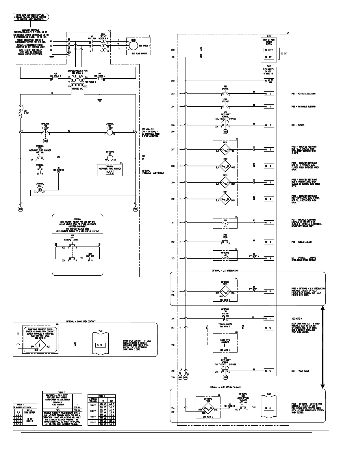
ELECTRICAL DIAGRAM, GENERIC
48
4111-0010 — Nov 2010

4111-0010 — Nov 2010
49

PARTS
A
C
Item Quantity Part Number Description
A 1 0961-0083 Proximity Switch with Harness (INTERLOCK Feature Only)
B 1 * Push Button Controller
C 1
*
Provide dock leveler serial number, voltage, phase, and options when calling or faxing controller orders.
50
9511-0004 J-Box, Standard (4 x 4 in. Metal Box)
9512-0429 J-Box, Cold Weather (5 x 5 in. Plastic Box)
4111-0010 — Nov 2010

Powerhook Guide Track Components
#3
PARTS
#6
D
E
C
D
E
H
G
I
FD
#5
EDA
B ED
#4
Item Quantity Part Number Description
A 1
0521-0143
Guide Track - Aluminum
B 1 0521-0144 Cable Assembly - Powerhook - Standard
C 1 0521-0173 Sensor Mounting Bracket
D 7 2101-0196 Nylon Lock Nut, 10-32 UNF
E 5 2101-0202 Round Head Machine Screw, 10-32 UNF x 1/2, Stainless Steel
F 2 2101-0203 Round Head Machine Screw, 10-32 UNF x 3/4, Stainless Steel
A-G 1 0524-0075 Powerhook Guide Track Assembly Complete
H 1 0521-0146 Guide Track - Pig Tail 46” Long
I 1 0521-0147 Guide Track - Pig Tail 94” Long
26-1/4”
Standard Length
A
18-3/4”
Standard length
Item Quantity Part Number Description
A 1 0521-0123 Powerhook Cylinder Only
B 1 7054-0001 Powerhook Arm Weldment
C 1 7054-0010 Powerhook Standard length
*Provide dock leveler and/or PowerHook serial number when calling or faxing orders.
4111-0010 — Nov 2010
B
51

PARTS
A
B
C
D
X
W
R
V
U
S
T
Q
E
H
N
O
P
M
L
J
G
Item Quantity Part Number Description
A 1 8585-0096 Valve Block Assembly - Regeneration (See Breakdown for Details)
B 1 7054-0010 Cylinder Assembly - PowerHook
C 1 9904-0110 Hydraulic Hose Assembly - 1/2” 100R1 x 20.00, #8 JIC
D 1 9301-0116 Fitting 90 Degree #8 ORBM, #8 JICM
E 2 2101-0012 Hex Head Cap screw, 5/16-18 UNC x 1-1/4
F 2 2101-0058 Lock Washer 5/16
G 1 0522-0061 Bar - Guide Rod
H 2 2101-0057 Hex Head Cap screw, 5/16-18 UNC x 1/2
J 2 2101-0058 Lock Washer, 5/16
K 1 2101-0059 Flat Washer, 1/4
L 1 0524-0075 Guide Track Assembly (See Guide Track Assembly Breakdown for Details)
M 1
0526-0005 Positioning Cylinder Assembly (With Breather)
0526-0006 Positioning Cylinder Assembly (With Weep Tube Fitting)
N 1 2101-0004 Flat Washer, 5/8
O 1 2101-0052 Hex Head Cap screw, 5/8-11 UNC x 2-1/2
P 1 2101-0042 Hex Nut, 5/8-11 UNC
Q 2 0522-0062 Trunnion - Positioning Cylinder, 3/8 x 3 x 4
R 2 2101-0041 Hex Nut, 1/2-13 UNC
S 2 2101-0051 Hex Head Cap screw, 1/2-13 UNC x 2-1/2
T 2 2101-0055 Lock Washer 1/2
U 1 2101-0058 Lock Washer, 5/16
V 1 2101-0059 Flat Washer, 1/4
W 1 2101-0068 Hex Head Cap screw
X 1 7052-0005 Bar - Prox Target, 1/2 x 1-1/2 x 1
F
52
4111-0010 — Nov 2010

PowerHook Valve Body Assembly
PARTS
20
19
18
1
2 4
3
17 16
7
5
6
8
9
10
21
11
15
14
13
12
Item# Part Description Bock Label Function Part Number
1 Cartridge Valve - 4-way - 2-position A Fluid to Powerhook or Dock Leveler if energized 8581-0011
2,5,8,12,14 Delta Coil Activates Cartridge Valve 8581-0004
3 Elbow 90º Fitting DLS Fluid to Logic Block 9301-0127
4 Cartridge Valve - 3-way - 2-position B Fluid to lower Powerhook if energized (with D) 8581-0005
6 Pressure Switch Assemebly PS Tells PLC to stop Powerhook retracting when ICC bar engaged 0963-0004
7 Cartridge Valve - 3-way - 2-position C2 Fluid to retract Powerhook when energized (with C1) 8581-0005
9 Elbow 45º Fitting HC2 Fluid to top of Powerhook cylinder via regeneration valve 9301-0120
10 Elbow 45º Fitting HC1 Fluid to base of Powerhook cylinder via regeneration valve 9301-0120
11 Elbow 45º Fitting HDC Fluid to positioning cylinder 9301-0120
13 Cartridge valve - 2-way - N.C. C1 Fluid to retract Powerhook when energized (with C2) 8581-0074
15 Cartridge valve - 3-way - 2-position D Fluid to hold Powerhook in lowered position when energized 8581-0005
16 Cartridge valve - Flow control NV Conrols fl ow to/from positioning cylinder 8581-0008
17 Cartridge valve -relief RV Controls fl ow to/from Powerhook, dumps excess fl ow to tank 8581-0089
18 T-Fitting R1 Return line (dump line) to pump 9301-0127
19 T-Fitting R1 Fluid to dock leveler - logic block 9301-0127
20 Incoming pressure line P1 Incoming hydraulic fl uid from pump varies by model
21 Cabel Assembly Wire harness, 48”, 5 wire assembly: connects to 5 delta coils 4305-0234
22 Cable individual (not shown) Individual wire, 48”, connects to single delta coil 4305-0235
4111-0010 — Nov 2010
53

PARTS
Power Pack Assembly
Vent Tube
J
H
D
E
F
C
G
K
L
M
Pressure
Line
AC
AB
P
N
54
B
A
PR006
AA
Z
Y
X
W
Q
R
S
T
U
Return Line
T
V
4111-0010 — Nov 2010

Power Pack Assembly
Item Quantity Part Number Description
A 2 2101-0039 Nylon Lock Nut, 5/16-18 UNC
B 2 9301-0029 Seal, Thread
C 1 9302-0014 Reservoir
D 1 9301-0199 Breather Cap, 3/8 NPT Male
E 1 9301-0027 O-Ring (Reservoir)
F 2 9302-0012 Tie Rod (Reservoir)
1 9301-____
G
4 2101-0016 Cap Screw, 5/16-18 UNC x 3-1/2 in., Grade 5
1 9301-0028 Gasket, Pump
1 9303-0002 Coupling Assembly
H 1 9302-0017 Plate, Drive
J 1 9904-0001 Hose
K 1 0521-0017 90° Elbow, 3/8 NPT Male x #8-JIC Male
L 1 0521-0007 90° Elbow, 1/4 NPT Male x 1/4 Tube
M 1 3411-____
N 1 0521-0015 Straight Fitting, 3/8 NPT Male x #8-JIC Male
P 1 0521-0014 Ball, Check
Q 1 9301-0024 Guide, Check Ball
R 1 9302-0009 Spring, Relief Valve
S 1 9303-0003 Screw, Adjusting
T 2 9301-0014 Washer, Nylon, 11/16 in. OD x 1/2 in. ID
U 1 9301-0015 Nut, Jam, 1/2-20 UNF
V 1 9301-0016 Nut, Acorn, 1/2-20 UNF
W 1 0521-0016 45° Elbow, 3/8 NPT Male x #8-JIC Male
X 1 9301-0009 Strainer, Suction
Y 1 9301-0082 Magnet
Z 1 9301-0008 Pipe Nipple, 3/8 NPT x 3 in.
AA 2 9301-0003 Washer, Aluminum, 9/16 in. OD x 3/8 in. ID x 1/16 in.
AB 2 9301-0004 Screw, Socket Head, 3/8-16 UNC x 1-3/4 in.
AC 2 2101-0063 Nut, Jam 5/16-18 UNC
1 9395-____
1
Pump Only
2
Motor Only
1
Power Pack Complete (Includes All Items Except L, N, and W)
PARTS
1
Provide dock leveler serial number and type of installation when calling or faxing orders.
2
Provide dock leveler serial number, voltage, and phase when calling or faxing orders.
4111-0010 — Nov 2010
55

PARTS
Pressure Differential Valve and Block
A
B
C
D
F
The Pressure Differential Valve takes the place of the Pressures Switch. The Pressure Differential
Valve tells the PLC to stop retracking when the Powerhook makes contact with the ICC bar.
Item Quantity Part Number Description
A 1 4305-0563 Cable Assembly, 48”
B 1 8581-0135 Pressure Differential Switch
C 1 8581-0090 Regeneration valve
D 3 9301-0116 Fitting, Elbow 90 Deg#8 O Ring To #8 Jic
E 1 9301-0126 Fitting, Union, Str
F 1 9904-0110
A-F 1 8585-0096 Pressure Differential Valve Complete
Hose, 1/2, 17” Lg #8 JicF Swivel Both Ends
E
56
4111-0010 — Nov 2010

Customer Information
MISCELLANEOUS
A
NOTE: Refer to illustration for left/right orientation of
dock leveler.
The model/serial number decal (A) is located
on the right platform joist near the front (lip)
of dock leveler.
When you receive your Poweramp product, write
down the product model and serial number in the
form provided. This will help ensure safe keeping of
the numbers in the event the model/serial number
decal (A) becomes lost or damaged.
Also, write down Systems, Inc.’s job number, the
company that installed the dock leveler, and the
original owner’s name. This will all help to identify the
specific dock leveler if more information is required.
When ordering, use part numbers and description
to help identify the item ordered. Do not use “item”
numbers. These are only for locating the position of
the parts. Always give dock leveler MODEL NUMBER
and/or SERIAL NUMBER.
For service, call or contact:
Dock Leveler Information
Model ___________________________________
Serial No. ________________________________
Systems, Inc., Job No. ______________________
Original Owner Information
Name ___________________________________
Address _________________________________
________________________________
Installer Information
Name ___________________________________
Address _________________________________
_________________________________
Date of Installation ________________________
Systems, Inc.
P.O. Box 309
Germantown, WI 53022
Phone: (800) 643-5424
Fax: (262) 255-5917
4111-0010 — Nov 2010
57

STANDARD PRODUCT WARRANTY
SYSTEMS, INC. warrants that its products will be free from defects in design, materials and
workmanship for a period of one (1) year from the date of shipment. All claims for breach of this
warranty must be made within 30 days af ter the defect is or can with reasonable care, be
detected. In no event shall any claim be made more than 30 days after this warranty has expired.
In order to be entitled to the benefits of this warranty, the product must have been properly
installed, maintained and operated in accordance with all manufacturer’s recommendations and/or
specified design parameters and not otherwise have been subject to abuse, misuse,
misapplication, acts of nature, overloading, unauthorized repair or modification, application in a
corrosive environment or lack of maintenance. Periodic lubrication, adjustment and inspection in
accordance with all manufacturers’ recommendations are the sole responsibility of the
Owner/User.
In the event of a defect, as determined by SYSTEMS INC., covered by this warranty, SYSTEMS
INC. shall remedy such defect by repairing or replacing any defective equipment or parts, bearing
the cost for the parts, labor and transportation. This shall be exclusive remedy for all claims
whether based on contract, negligence or strict liability.
WARRANTY LIMITATIONS
THE ABOVE WARRANTIES ARE IN LIEU OF ANY OTHER WARRANTIES, WHETHER
EXPRESSED OR IMPLIED, INCLUDING BUT NOT LIMITED TO ANY IMPLIED
WARRANTY OF MERCHANTABILITY OR FITNESS FOR A PARTICULAR PURPOSE.
SYSTEMS INC. AND ITS SUBSIDARIES SHALL NOT IN ANY EVENT BE LIABLE TO
ANYONE, INCLUDING THIRD PARTIES, FOR INCIDENTAL, CONSEQUENTIAL OR
SPECIAL DAMAGES OF ANY KIND INCLUDING BUT NOT LIMITED TO, BREACH OF
WARRANTY, LOSS OF USE, LOSS OF PROFIT, INTERUPTION OF BUSINESS OR LOSS
OF GOODWILL.
PRODUCT SPECIFIC WARRANTY
“POWERHOOK®” SERIES LEVELER
In addition to the “Standard Product Warranty” provided with all Poweramp® Products, Systems
Inc., guarantees materials, components and workmanship to be free of defects for the following
extended periods:
• Structural Warranty – For a period of five (5) years from the date of shipment, this
warranty specifically applies to; the deck section, lip section, frame, rear hinge assembly
and front hinge assembly only.
• Hydraulic Warranty – For a period of five (5) years from date of shipment, this warranty
specifically applies to; the hydraulic pump and motor, all hydraulic cylinders, hydraulic
pressure lines and fittings and fluid control assemblies only.
• Electrical Warranty – For a period of two (2) years from date of shipment, this warranty
specifically applies to; the control box components, guide track assembly, pressure
differential switch, coils and proximity sensor when interlocked with Poweramp® dock
leveler only.
 Loading...