


POWERHOLD AND
POWERHOLD SC
TRUCK RESTRAINT
INSTALLATION AND
OPERATION MANUAL
Job Number
Job Name
Serial Numbers
SYSTEMS, INC.
P.O. BOX 309
Germantown, WI 53022
Phone 414-255-1510
Fax 414-257-7399
11/06


INDEX
SECTION
I. INSTALLATION
A. MOUNTING AND ANCHORING ................................................................................................. 1
B. ELECTRICAL ............................................................................................................................ 2
C. HYDRAULIC ............................................................................................................................. 2
II. GENERAL INFORMATION
A. DESCRIPTION OF OPERATING MODES ................................................................................. 3
B. DESCRIPTION OF SIGNAL LIGHTS ......................................................................................... 4
C. SIGNAL LIGHTS AND ALARM SEQUENCE OF OPERATION ................................................... 5,6
D. OPERATING NOTES ................................................................................................................ 6-7
III. OPERATING INSTRUCTIONS
A. NORMAL OPERATION ............................................................................................................. 8
B. BYPASS OPERATION .............................................................................................................. 8-9
IV. MAINTENANCE
A. CLEANING ................................................................................................................................9
B. LUBRICATION ........................................................................................................................... 9
C. HYDRAULIC FLUID CHECK ...................................................................................................... 9
D. SIGNAL LIGHTS CHECK .......................................................................................................... 9
PAGE
V. MECHANICAL RELEASE .................................................................................................................. 10
VI. PARTS LISTS AND ILLUSTRATIONS ................................................................................................. 11-15
NOTE: Control unit shipped may be
different than what is shown.
NOTE: Outside Light Assembly
shipped may be different than what
is shown.

INSTALLATION
MOUNTING AND ANCHORING
Inspect installation location: The POWERHOLD restraint will require solid anchors to
assure proper operation. Optimum installations will have both a concrete drive and a
poured concrete dock face so that anchor bolts can be well secured. Twelve 1/2"
anchor bolt mounting holes are re provided. However, 6 base or 6 wall may be used
where cold induced frost heave will be a factor or mounting conditions do not allow use
of all 12 mounting holes.
The POWERHOLD restraint should be positioned at the center of the dock leveler and
is designed to be flush with the dock face when 4-1/2" bumpers are used. A filler plate
(not supplied with POWERHOLD systems) will be required for bumper projections
greater than 4-1/2" as follows:
BUMPER FILLER PLATE
6" 1-1/2"
8" 3-1/2"
10" 5-1/2"
IMPORTANT
The restraint should be installed level from top to back and from side
to side. The restraint should be installed square with the face of the
dock.
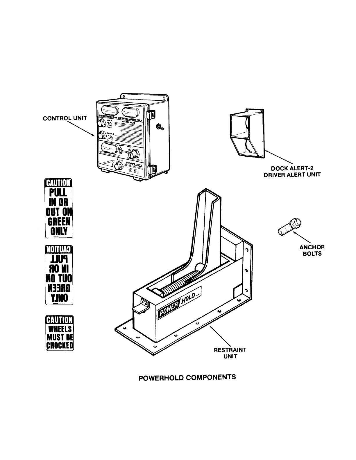
Typical mounting requirements for the control unit, driver alert unit and "CAUTION PULL
IN OR OUT ON GREEN ONLY" signs are shown in the illustration below. The
"CAUTION WHEELS MUST BE CHOCKED" sign should be mounted FOR EASY
READING BY TRUCK DRIVER outside and to the right of the overhead door or at the
right side of the loading dock. Fasteners for these three caution signs are not included
with the POWERHOLD system.
1

INSTALLATION CONTINUED
ELECTRICAL
Refer to the drawings indicated in Table I for the electrical installation. The drawings are
attached to this manual.
IMPORTANT
Make sure that the power supply requirement(s) as shown on the electrical
drawings and on the decal of the control assembly(s) are the correct
requirement(s) for the application.
TABLE I
DRAWING
DESCRIPTION
FIELD WIRING
DRAWING
INTERCONNECTION
DRAWING
INFORMATION ON DRAWING
- ELECTRICAL DATA
- RECOMMENDED WIRE SIZES
- REQUIRED CONDUIT RUNS
- REQUIRED FIELD WIRES PER CONDUIT RUN
- REQUIRED CONDUIT RUNS
- REQUIRED FIELD WIRES PER CONDUIT RUN
- TERMINATION POINTS FOR ALL FIELD WIRES
HYDRAULIC
Standard units are factory pre-connected so that no hydraulic field connections are
required. Standard units are shipped with a full reservoir of hydraulic fluid. In the event
of a fluid loss during shipment or installation, information concerning fluid
replenishment can be found in the maintenance instructions section of this manual.
2

GENERAL INFORMATION
DESCRIPTION OF OPERATING MODES
A. "NORMAL" OPERATING MODE
Used to operate the POWERHOLD restraint to engage the truck ICC bar. An
auto-raise cycle will be activated by momentary pressure on the "LOCK" push
button (Note: Pressure on the "LOCK" push button must be maintained until
the inside lights change from red to amber). An AUTO-LOWER cycle will be
activated by momentary pressure on the "UNLOCK" push button. If no truck
ICC is engaged, the unit will automatically return to the stored position and an
alarm will turn on. The inside and outside signal lights will automatically
change as the unit reaches different positions in the raise and lower cycle.
B. "BYPASS" OPERATING MODE
Used when the truck does not have a serviceable ICC bar or if operating the
POWERHOLD restraint may damage equipment on the truck. The restraint
cannot be operated in this mode. The inside lights are amber and the outside
lights are red at all times in this mode. The truck wheels must be chocked
when operating in this mode.
3
GENERAL INFORMATION CONTINUED
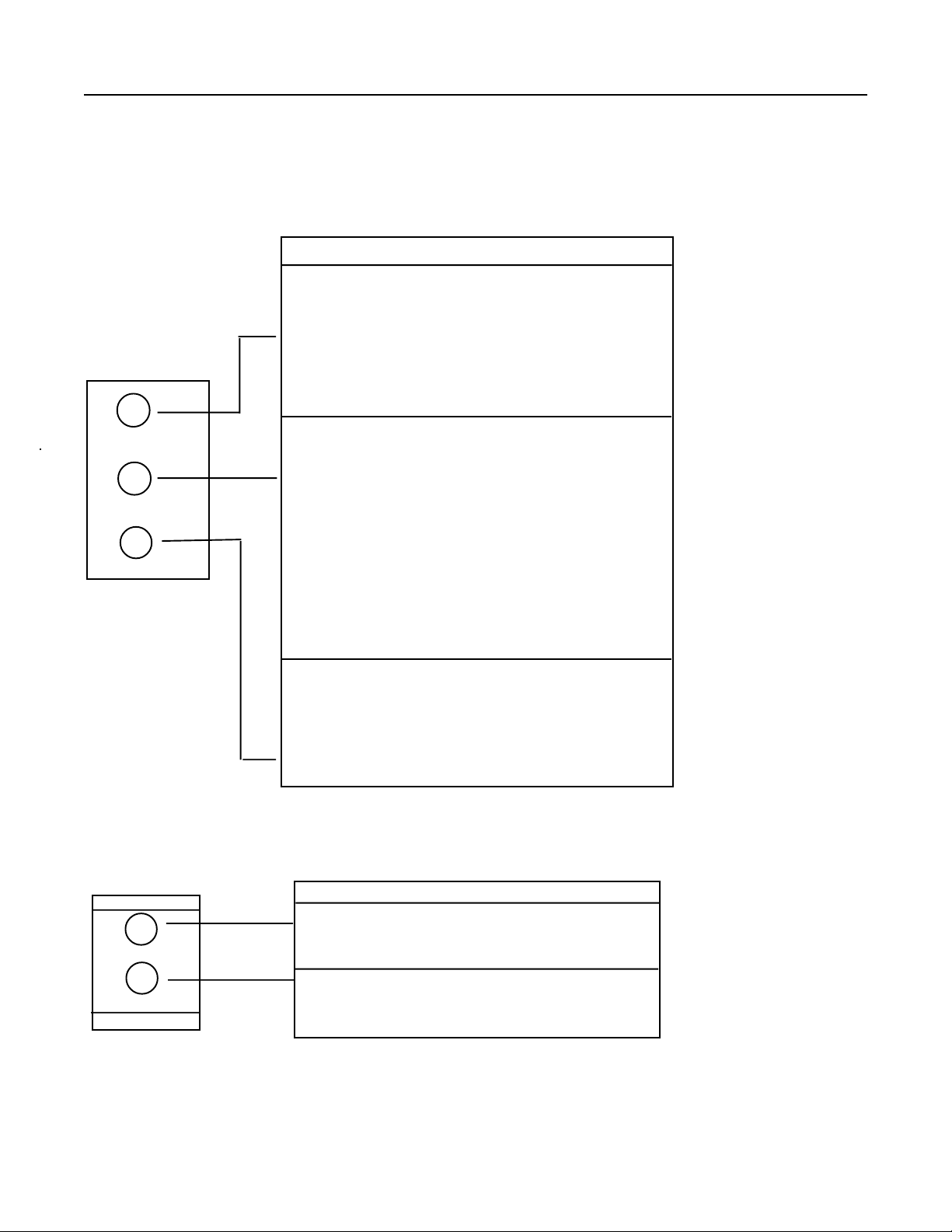
DESCRIPTION OF SIGNAL LIGHTS:
A. INSIDE SIGNAL LIGHTS. These lights are typically located on the PLC/
LOGIC control assembly. the assembly housing the light is to be
mounted in a location that is clearly visible to the dock attendant.
WHEN THE LIGHT IS ON:
RED LIGHT
• IT INDICATES TO THE DOCK ATTENDANT THAT IT IS
NOT OK TO ENTER THE TRUCK. THE TRUCK ICC
BAR IS NOT ENGAGED BY THE POWERHOLD
RESTRAINT. THE BYPASS MODE AND WHEEL
R
CHOCKS MAY BE REQUIRED.
AMBER CAUTION LIGHT
A
G
B. OUTSIDE SIGNAL LIGHTS. These lights are located in the outside signal light
assembly. This light assembly is mounted in a location that is clearly visible to
the truck operator.
• IT INDICATES TO THE DOCK ATTENDANT THAT IT IS
NOT OK TO ENTER THE TRUCK WHEN IN THE
"NORMAL" OPERATING MODE. THE UNIT HAS
BEEN ACTIVATED BUT HAS NOT ENGAGED THE
TRUCK ICC BAR. OR
• IT INDICATES TO THE DOCK ATTENDANT TO ENTER
WITH CAUTION WHEN IN THE "BYPASS"
OPERATING MODE. THE TRUCK ICC BAR IS NOT
ENGAGED BY THE POWERHOLD RESTRAINT.
GREEN LIGHT
• IT INDICATES TO THE DOCK ATTENDANT THAT IT IS
OK TO ENTER THE TRUCK . THE TRUCK ICC BAR
IS ENGAGED BY THE POWERHOLD
RESTRAINT.
WHEN THE LIGHT IS ON:
IT INDICATES TO THE TRUCK OPERATOR
R
THAT IT IS NOT OK TO BACK IN OR PULL
AWAY FROM THE DOCK.
G
OUTSIDE SIGNAL
LIGHT ASSEMBLY.
4
IT INDICATES TO THE TRUCK OPERATOR
THAT IT IS OK TO BACK IN OR PULL AWAY FROM
THE DOCK.

GENERAL INFORMATION CONTINUED
SIGNAL LIGHTS AND ALARM SEQUENCE OF OPERATION
A. "NORMAL" operating mode - truck ICC bar engaged.
1. The POWERHOLD restraint is in the fully lowered (stored) position. Limit
switch "LS3" is closed.
Outside light = Green
Inside light = Red
Alarm = Off
2. The POWERHOLD restraint is activated.
a. The unit leaves the fully lowered (stored) position. Limit switch
"LS3" is open.
Outside light = Red
Inside light = Amber
Alarm = Off
b. The unit reaches the fully raised ICC bar engaged position, Proxim
ity switches "LS1" and "LS2" are closed.
Outside light = Red
Inside light = Green
Alarm = Off
B. "NORMAL" operating mode - truck ICC bar not engaged.
1. The POWERHOLD restraint is in the fully lowered (stored) position, Limit
switch "LS3" is closed.
Outside light = Green
Inside light = Red
Alarm = Off
2. The POWERHOLD restraint is activated.
a. The unit leaves the fully lowered (stored) position. Limit switch
"LS3" is open.
Outside light = Red
Inside light = Amber
Alarm = Off
b. The unit reaches the fully raised no ICC bar engaged position.
Proximity switch "LS1" is closed.
Outside light = Red
Inside light = Amber
Alarm = On
(Note: The alarm stays on until the unit reached the lowered position).
5

GENERAL INFORMATION CONTINUED
SIGNAL LIGHTS AND ALARM SEQUENCE OF OPERATION CONTINUED.
D. The unit reaches the fully lowered (stored) position.
Limit switch"LS3" is closed.
Outside light = Green
Inside light = Red
Alarm = Off
D. "BYPASS" operating mode
Outside light = Red at all times
Inside light = Amber at all times
Alarm = Off at all times
OPERATING NOTES
A. When in the "NORMAL" operating mode, the raise cycle of the restraint will be
activated by momentary pressure on the "LOCK"push button (auto raise cycle).
However, the auto raise cycle will only be activated if pressure on the "LOCK"
push button is maintained long enough to allow the restraint to leave the stored
position (i.e., leave the "LS3" limit switch). This will ensure that the dock
attendant does want the restraint to be activated. The inside lights will change
from RED to AMBER when the restraint leaves the stored position.
B. When in the "NORMAL" operating mode, the lower cycle of restraint will be
activated by momentary pressure on the "UNLOCK" push button (auto lower
cycle). The inside lights will change from GREEN to AMBER when the restraint
leaves the fully raised, ICC bar engaged position.
C. The automatic raise and lower cycles are backed-up with time based failure
mode protection, described as follows:
1. Automatic raise cycle:
If the restraint does not reach the fully raised ICC bar engaged position or
the fully raised no ICC bar engaged position within approximately 13
seconds after leaving the stored position, the restraint will automatically
return to the stored position. Failure to reach the fully raised ICC bar
engaged position or the fully raised no ICC bar engaged position can be due
to an obstruction preventing the restraint from raising.
Also, the restraint will automatically return to the stored position after the
13 second delay if the unit reaches the fully raised ICC bar engaged
position but the "LS1" proximity switch in the unit has failed "OPEN".
(Note: If the restraint reaches the fully raised ICC bar engaged position but
the "LS2" proximity switch in the unit has failed "OPEN", the automatic
return cycle (with alarm) will be activated).
2. Automatic return cycle (no ICC bar) and automatic lower cycle:
If the restraint does not reach the stored position within approximately 13
seconds after leaving the fully raised ICC bar engaged position or the fully raised
no ICC bar engaged position, the restraint will automatically shut off. Failure to
reach the stored position can be due to an obstruction preventing the restraint
from lowering.
6

GENERAL INFORMATION CONTINUED
Also, the restraint will automatically shut off after the 13 second delay if the unit
reaches the stored position but the "LS3" limit switch in the unit has failed
"OPEN".
D. If power is lost after the restraint is activated, the automatic raise and lower cycles
will be disabled. Thus, when power is restored the restraint must be reactivated to
either the fully raised ICC bar engaged position or the stored position. If the restraint is
not in the stored position or the fully raised ICC bar engaged position when power is
restored, the alarm will turn on and off (10 seconds on, 50 seconds off) for
approximately 10 minutes. This serves as an indication that the restraint should be
activated to either the stored position or the fully raised ICC bar engaged position. The
alarm will turn off when either the "LOCK" or "UNLOCK" push buttons are pressed.
NOTE: THE ABOVE DESCRIPTION IS FOR AN AUDIBLE ALARM. IF THE UNIT
IS EQUIPPED WITH A VISUAL ALARM THE ALARM WILL STAY ON
CONTINUOUSLY FOR 10 MINUTES AFTER POWER IS RESUMED. AUDIBLE
ALARMS ARE TYPICALLY SUPPLIED. VISUAL ALARMS ARE SUPPLIED
UPON CUSTOMER REQUESTS AND/OR FOR APPLICATIONS REQUIRING
NEMA 4 RATED CONTROLS.
E. The restraint cannot be operated in the "BYPASS" operating mode.
7

OPERATING INSTRUCTIONS
NORMAL OPERATION
1. Set the "ON-OFF" switch to "ON".
2. Set the "NORMAL-BYPASS" key switch to "NORMAL".
3. Requirements for proper restraint operation are that the truck be parked
perpendicular to the loading dock area with its ICC bar from 4-1/2" to 14-1/2" from
the face of the dock when 4-1/2" bumpers are used. If 6" bumpers are used, the
horizontal range would be from 6" to 16" from the face of the dock.
4. Inspect the truck to ensure that no truck equipment will be damaged by operating
the POWERHOLD restraint.
5. Press the "LOCK" push button until the inside light changes from RED to AMBER.
This will activate the auto-raise cycle of the restraint.
A. If the restraint engages the truck ICC bar, the inside lights will change from
AMBER to GREEN. Proceed with loading/unloading of truck.
B. If the restraint does not engage the truck ICC bar, the inside lights will remain
AMBER and an alarm will turn on while the restraint automatically returns to the
stored position. The lights will change to RED and the alarm will turn off when the
restraint reaches the stored position. Follow the "BYPASS" operating instructions.
6. Press the "UNLOCK" push button until the inside lights change from GREEN to
AMBER. This will activate the auto-lower cycle of the restraint. The inside lights
will change from AMBER to RED when the restraint reaches the stored position.
BYPASS OPERATION
1. Set the "ON-OFF" switch to "ON".
2. Set the "NORMAL-BYPASS" key switch to "BYPASS". The inside lights will
change to AMBER, the outside lights will change to RED.
3. Chock truck wheels.
4. Proceed cautiously with loading/unloading of truck.
8

MAINTENANCE
CLEANING
The POWERHOLD restraint should be kept free of debris, ice, dirt and sand. Build-ups
of foreign material, especially on the top of the slide block assembly, could result in
abnormal operation of the restraint.
LUBRICATION
Lubrication should be performed on a monthly basis. Use Lubriplate No. 18339 multipurpose grease or equivalent.
Remove all of the old grease from the slide block guide channels and from the top of
the slide block before applying the new grease. The slide block guide channels are
located inside the unit, on the sides of the housing weldment.
Use the grease zerks located outside the unit, on the sides of the housing weldment to
lubricate the slide block guide channels and the restraint weldment pivot point. Also,
apply a liberal amount of grease on top of the slide block, especially at the areas of the
slide block on which the restraint weldment "rides".
NOTE: DO NOT GREASE THE TOOTHED PORTION OF THE RATCHET BAR OR
LOCKING MECHANISM.
HYDRAULIC FLUID CHECK
The hydraulic fluid level should be checked every month. Fluid level should be
approximately 1-1/2" from the top of the reservoir when the restraint is in the fully
lowered (stored) position.
To assure normal operation of the restraint the following fluids are recommended:
Flowmite 530 ZF available from Systems, Inc.
Aero shell fluid #4 code or #41 by Shell Oil Co.
Mobile Aero HFA Mil-HS606A or Aero HF by Mobil Oil Co.
Texaco Aircraft Hydraulic Oil 15 or 5606
Exxon UNIVIS J13
NOTE: Use of hydraulic fluids with equivalent specifications to those listed is
acceptable. Use of fluids that do not have equivalent specifications will result
in abnormal operation of the unit.
SIGNAL LIGHTS CHECK
To assure dock attendant safety, check to make sure that the inside and outside
signal lights function correctly. This check should be performed on a weekly basis. The
correct sequence of light operation can be found in the general information section of
this manual.
9

MECHANICAL RELEASE
The POWERHOLD restraint is equipped with a mechanical release that can be
utilized in the event of an electric and/or hydraulic failure which prevents the unit from
releasing the truck ICC bar via normal operating methods.
MATERIAL REQUIRED
1-1/8" Wrench
Phillips head screwdriver
2-1/2' or longer, 3/4" rod
Hammer
Oil (WD-40 or equivalent)
WARNING - POSSIBILITY OF SERIOUS INJURY
Keep all body parts out of the working zone of the restraint weldment at all
times when performing a mechanical release.
PROCEDURE
1. Make sure outside signal lights are red.
2. Chock truck wheels.
3. Apply a liberal amount of oil to the top of the slide block (P/N 9413-0022).
4. Use the screwdriver to remove the front cover plate (P/N 9411-0012) from the front
of the housing weldment (P/N 9414-0029). This requires the removal of four
screws.
5. Use the wrench to remove the capscrew (P/N 2101-0118) from the front of the
housing weldment.
6. Insert the 3/4" rod through the front of the housing weldment (i.e., through the
area of the weldment opened by the removal of the front cover plate). Set one end
of the rod into the hole located in the front of the slide block.
7. Hammer on the exposed end of the 3/4" rod to force the slide block towards the
face of the dock. The restraint weldment (P/N 9414-0014) should lower when the
slide block is repositioned.
8. After truck is released and away from the restraint, reassemble the unit.
9. Determine cause of electric and/or hydraulic failure.
10

POWERHOLD
END RELEASE
18
34
36
21
17
38
41
11
12
13
8
22
27
28
30
31
32
33
20
19
23
29
35
15
16
25
40
39
26
24
36
4
7
5
3
6
9
1
2
11

POWERHOLD END RELEASE
PARTS LIST
ITEM DESCRIPTION PART NUMBER
1 HOUSING WELDMENT 9414-0029
2 FRONT COVER PLATE 9411-0012
3 SCREW 2101-0099
4 LATCH WELDMENT ASSY For 23" Restraint Weldment 9414-0037
*Complete Assembly with Prox Switches
4 LATCH WELDMENT For 19" Restraint Weldment 9414-0042
*Complete Assembly with Prox Switches
5 PROX. SWITCH-RATCHET AC-RELAY EQUIPPED 0961-0035
5 PROX. SWITCH-RATCHET DC-PLC (Current Production) 0961-0073
6 LIMIT SWITCH-STORED (Discontinued 2003) 0961-0037
7 PROX. SWITCH-CYLINDER AC-PLC Equipped (Discontinued) 0961-0035
7 PROX. SWITCH-CYLINDER DC-PLC Equipped (Current) 0961-0073
8 SPRING SERVALITE 0941-0009
9 CAP SCREW 2101-0100
10 PROX. SWITCH LOCK NUT (NOT SHOWN) ----------------
11 BAR-SPRING LEVER 9414-0017
12 CAP SCREW-JAM 2101-0011
13 WASHER 2101-0003
14 CAP SCREW-PIVOT 5/16-18X2 (NOT SHOWN) 2101-0013
15 PUSH ROD 9412-0095
16 CLIP ----------------
17 RACK WELDMENT 9414-0021
18 RESTRAINT WELDMENT 23" (Discontinued) 9414-0014
18 RESTRAINT WELDMENT 19" (Current) 9414-0049
19 CYLINDER ASSEMBLY 9414-0038
20 SLIDE BLOCK ASSEMBLY (Included with Cylinder Assy) 9413-0022
21 PIN 9412-0030
12

POWERHOLD END RELEASE CONTINUED
ITEM DESCRIPTION PART NUMBER
22 BAR-WEATHERSEAL HOLD DOWN 9411-0007
23 BAR-REMOVABLE TRACK STOP (LH/RH) 9412-0063
24 ELECTRICAL BOX 2752-0029
25 SHROUD 9411-0015
26 COVER & GASKET (ELEC. BOX) 2751-0058
27 SCREW - FRONT PLATE 2101-0076
28 WEATHERSEAL 0192-0016
29 HOSE ASSY - 22" 9904-0039
30 HYDRAULIC VALVE ASSEMBLY 8583-0017
31 BODY WITH SPOOL Discontinued
32 4-WAY SOLENOID SPOOL 8581-0011
33 SOLENOID COIL 8581-0004
33 SOLENOID COIL HARNESS 4301-0004
34 HOSE ADAPTER 90 DEGREES EL 0521-0042
35 HOSE ASSY 35" 9904-0040
36 HOSE ADAPTER STREET 0521-0043
37 CAPSCREW 2101-0074
38 SPRING 9411-0005
39 CAPSCREW - TRACK STOP 2101-0069
40 SCREW 2101-0076
41 CAPSCREW 2101-0118
NOTE: Solenoid Valve, Coil and Harness above are Delta Brand. Older units may have Parker or
Parker-Waterman brand components that are no longer available. If replacing an obsolete Valve, Valve
Assy or Coil the following Delta brand parts will be required:
* Valve Assembly (Includes solenoid valve and block) 8583-0017
* Solenoid Coil 8581-0004
* Solenoid Coil Harness 4301-0004
13

POWERHOLD
SELF CONTAINED
46
45
49
55
48
47
42
43
44
45
1
50
43
51
52
53
54
14

POWERHOLD SC (SELF CONTAINED)
POWERPACK PARTS
ITEM DESCRIPTION PART NUMBER
42 SHROUD - MOTOR 9412-0107
43 CAPSCREW 2101-0009
44 90 DEGREE STREET ELBOW 9301-0034
45 HOSE ADAPTOR - 90 DEGREE ELBOW 0521-0076
46 HOSE ASSY - 14" 9904-0038
47 PUMP 9301-0084
48 FILTER 9301-0085
49 BREATHER CAP 9301-0020
50 RESERVOIR 9303-0010
51 NIPPLE 9301-0045
52 MOTOR 3411-0008
53 TEE 9301-0012
54 HOSE ASSY - 11" 9904-0041
55 ELEMENT 9301-0086
15

SYSTEM'S, INC. STANDARD WARRANTY
POWERHOLD VEHICLE RESTRAINT
Poweramp warrants the locking unit, welded main frame, hydraulic cylinders and hoses, and all
electrical components to be free of defects in material and workmanship for a period of one (1)
year when installed and used in accordance with the Powerhold Owner’s Manual. Systems, Inc.
further guarantees the hydraulic components except for the solenoid valves on all Powerhold
units for a period of one (1) year from date of shipment. Specifically, this guarantee applies to (1)
hydraulic cylinders, (2) pressure lines provided by the factory and (3) the hydraulic pump and
motor.
In the event of any defect covered by this warranty, manufacturer will remedy said defect by
repairing or replacing all defective parts, bearing all of the costs for parts, labor and
transportation.
All warranty claims will be settled on a timely basis when defects are found to be from other than
improper installation, operating contrary to instructions or beyond rated load capacities, abuse,
careless or negligent use, or failure to maintain the unit as recommended by the owner’s manual.
There are no warranties, either expressed or implied, including any implied guarantees of
merchantability or fitness for a particular purpose which shall extend beyond the guarantee
periods indicated above. This guarantee is valid only if the unit(s) is unaltered from original
condition as delivered from the factory and a survey is completed by a Poweramp
representative.
 Loading...