

Page 1
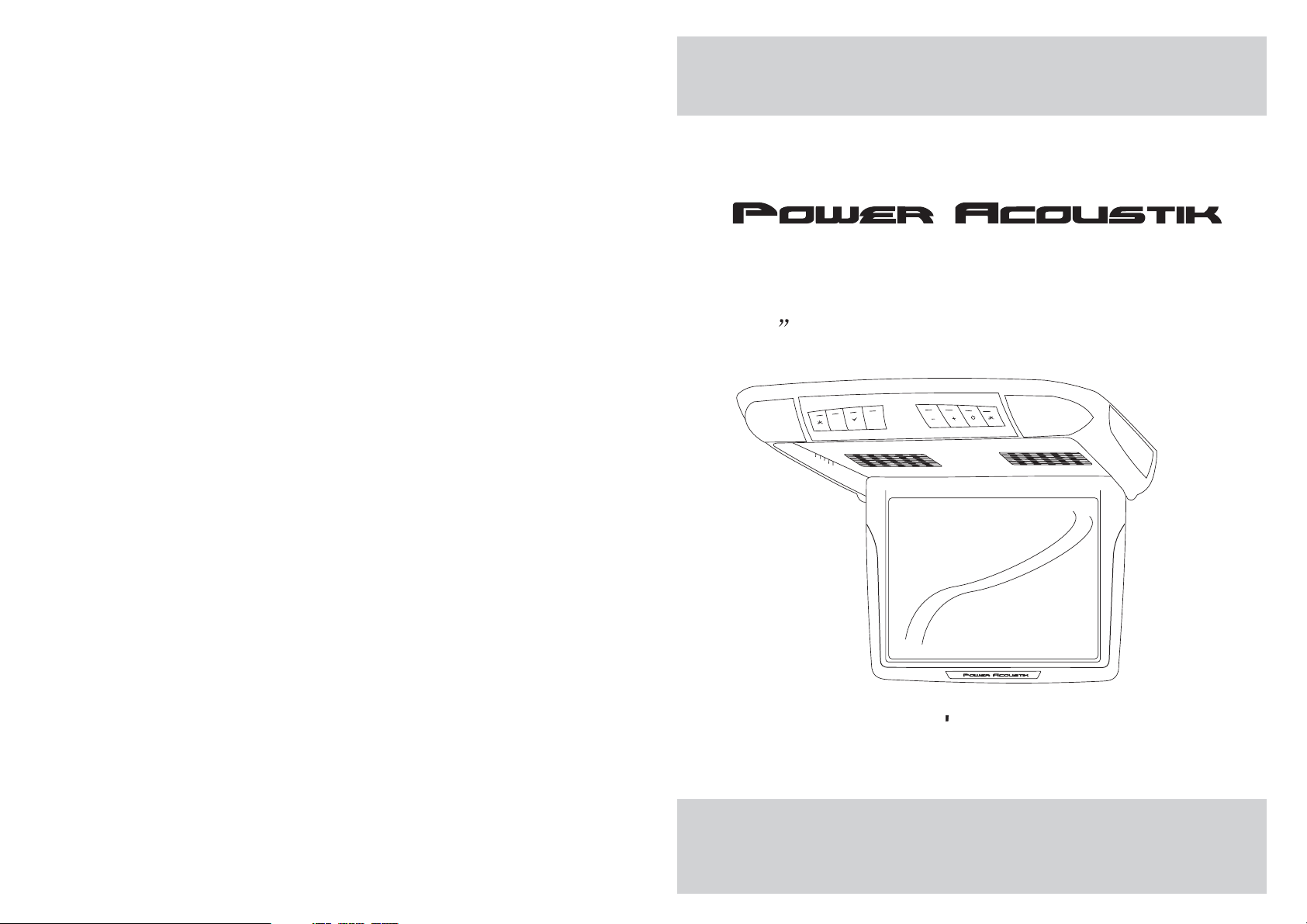
PT-120CM
12.1 Universal Ceiling Mount Monitor
M
E
MENU
AV
EXIT
POWER
OWNER S MANUAL
Page 2

Page 3

CONTENTS
Please read this User,s Manual in detail and use the set properly.
CAUTION 3
INSTALLATION 5
NAME AND FUNCTION OF EACH PART 6
Unit 6
Remote Control 7
PICTURE CONTROL 8
CONNECTIONS 9
HOW TO OPERATION THE MONITOR 10
Releasing The Monitor 10
How To Watch Monitor 10
SPECIFICATIONS 11
2
Page 4

CAUTION
Please read and observe all warnings and instructions in this owner s manual
,
and those marked on the unit. Retain this booklet for future reference.
There aretwo kinds of alarm symbols as follows:
The lightening flash with arrowhead symbol within an equilateral
WARNING
triangle is intended to alert the user to the presence of
dangerous voltage within the product s enclosure that may be
of sufficient magnitude to constitute a risk of electric shock to
people.
,
The exclamation point within an equilateral triangle is intended
to alert the user to the presence of important operating and
maintenance (servicing) instructions in the literature accompanying
CAUTION
the product.
WARNING
Installation of allTVmonitors
P
O
W
E
R
A
V
MEN
U
must be outofthedrivers
field of sight.
Do not mounttheproductwhere
it will obstructthedeploymentof
the airbag orinanareawhereit
would affectthevehicularcontrol.
Also be carefultoavoidmounting
the product whereitcanbecome
hazardous during suddenstopsor
in the eventofanaccident.
Do not tryandservicethese
products yourself, Seekonly
a qualified servicecenteror
factory service center.
Be careful nottodropor
apply under pressuretothe
front panel ofyourvideo
monitor.Ifthe screen cracks
due to misuse,yourwarranty
will be void!
Use extra cautionwithanyliquids
in your car. If you or your child
Spills any liquidontheseproducts,
pull your vehicletotheroadside
or wipe theproductswithatowel.Donot
operate the equipmentuntilallliquidshave
either evaporated oryouhavehadthemonitor
inspected at aservicecenterbyaqualified
technician, Severe harmordangercan
Occur.
and turn thekeyofftodisconnect
Use only adampclothtoclean
the screen anduseonlypurified
water on thecloth.Wringoutall
excess water priortowipingthe
screen. Do notuseanycleaners
or chemicals tocleanthescreen.
In most casesadryclothwilldo!
3
Page 5

SPECIFICATIONS
CAUTION
CAUTION
Power Requirements
Power Consumption
Screen Size
Screen Format
Resolution Pixel
A/V Inputs
Dimensions(
Dimensions(Without shroud)
IR Power Requirements
IR Power Consumption
IR Transmitter Frequency
LCD Panel Type
Compatible video standard
Note : This equipment has beentested and found to comply withthe limits for
a ClassAdigitaldevice, pursuant to part 15 ofthe FCC Rules. These limits
are designed to provide reasonable protectionagainst harmful interference
when the equipment is operated ina commercial environment.
This equipment generates, uses, and canradiate radio frequency energy and,
if not installed and used inaccordance with the instruction manual,may cause
harmful interference to radio communications. Operationof this equipment in
a residential area is likely tocause harmful interference in whichcase the user
will be required to correct theinterference at his own expense.
With shroud)
DC 12V
9W
12.1 TFT-LCD
4:3
2400x600
2 A/V RCA Inputs
15.1(L)X13.9(W)X3.5(H)inches
14.8(L)X13.6(W)X2.5(H)inches
DC 12V
3W
Right 2.8MHz Left 2.3MHz
Active Matrix TFT
NTSC/PALAuto Select
Quality installations are best
performed by qualified and
certifled installers.
Don t touch the unit ifthere is
a flash of lightning. It may
receive an electric shock.
Do not cover heater ducts orvents.
This may cause a fire oran electric
shock.
Watchingthemonitor for an
extended period of time
with the engine turned off
may deplete the vehicle s
battery.
This product is designed for
operation with a 12 Volt DC,
negative ground vehicle. It
is not suitable for operation
under other conditions or
voltages.
Check Point
1.The operating temperature of this product islimited to 14 F~140 F
(-10 C~60 C).
Your vehicle can reach temperaturesup to 100 C inthe summertime.
2. When yourvehicle is extremely hot or cold youmust allow time for your air
conditioner or heaterto cool or heat the vehicle andfor operating temperatures
to return tonormal operating ranges. Yourmonitorwill return to its normal
functions when theseoperating ranges are achieved.
3. Optimum picturequality is achieved when you are directlyin front of the monitor
(+/-45 degrees).
4. If thebuttons get stuck, please try to pressthe up of buttons, it will getback.
It won't impactusing normal.
5. If youcann't find the files name in listwhen playing, please reset units or turn
off/onover again.
6. If theunit cann't be change mode when playingsome special files which the
unit didn't support,please reset units or turn off/on over again.
11
4
Page 6

INSTALLATION
HOW TO OPERATE THE MONITOR
1. Open thepackage and check that these items arepresents.
INSTALLATION PLATE
2. Connect theexternal compoments to the RCAcableorAVoutput.
(Refer to theconnection diagram on page 9)
3.Match the positionof installation bracket and
UNIT
installation plate withscrewA.
SCREWA SCREW B
Releasing the Monitor
Push the openbutton (located on the front edge ofthe screen housing)
and lower themonitor to the desired angle.You can alsoadjust the
swivel angle.
Make thisarrowinDOWN
direction only.
PULLBUTTON
How to watch the monitor
4.Tightenthe unit with the supplied
screw B.
1. Connect themonitor to the external devices.
2. Press thePOWER button on either the remote controlor the unit once to turn
the power on.
Press the samePOWER button to turn the power off.
POWER
POWER
UNIT
3.Turnon the external devices and view.
5
REMOTE CONTROLLER
10
Page 7

CONNECTIONS
NAME AND FUNCTION OF EACH PART
Unit
+ 12 V DC Battery
Chassis Ground
ACC
DVD/VCD/CD/CD-R/CD-RW/MP3
PLAY/PAUSE PREV NEXT STOP DVD REMOTE AV EJECT POWER A/V INPUT
YELLOW
BLACK
RED
Reset
Red AUDIO(R)
White AUDIO(L)
Yellow VIDEO
Door Trigger
WHITE
AV Input
(AV 2)
Red AUDIO(R)
White AUDIO(L)
Yellow VIDEO
AV Input
(AV 1)
DVD/VCD/CD/CD-R/CD-RW/MP3
PLAY/PAUSE PREV NEXT STOP DVD REMOTE AV EJECT POWER A/V INPUT
Dome light
Reset
M
E
MENU
AV
EXIT
POWER
Infrared Transmitter
Monitor
(Front)
AUDIO VIDEO
RL
AV2INPUTS
+ DoorTrigger -
Monitor
RESET
(Rear)
9
6
Page 8

NAME AND FUNCTION OF EACH PART
PICTURE CONTROL
OSD MENU EXIT Button
E
EXIT
Dome Light Button
MENU Button
M
MENU
AV
AV Select Button
POWER Button
POWER
Dome Light Button
+/- Buttons
Interface Switch Function
Power Power ON/OFF
AV Signal Select
Menu Press this button for OSD menu.
And select menu option
+
Increase current option value.
-
Decrease current option value.
Contrast/Brightness/Color
To adjust CONTRAST,BRIGHTNESS,COLOR press the MENU button until you
arrive at thescreen for that item. Use the arrowbuttons to adjust the value. Press
the MENU buttonto make another adjustment or leave theMENU system.
1. Bring upthe on-screen function menu by pressing theMENU button on the unit
or the remotecontrol.
2. Press theMENU button on the unit or theremote control of monitor until you see
the item youwish to adjust.
3. Use thearrow buttons to adjust the value.
4. Press theMENU button to make another adjustment orleave the MENU system.
CONTRAST
50
BRIGHTNESS
50
COLOR
50
POWER KEY
-KEY
LCD MONITOR
REMOTE CONTROL UNIT
7
AV1/AV2 KEY
MENU KEY
+KEY
8
Page 9

Page 10

 Loading...