

B
C
INSTALLATION & CONNECTIONS
MIC
PLASMA 1
INSTALLATION & CONNECTIONS:
The PL-1 is designed to provide you with many years of continuous use
without failure. The display area consists of a complex matrix of
coloured light particles, revealing three (3) separate colours when
suciently excited; RED, WHITE & BLUE… colours we can all relate to!
Before you begin, please take the time to read and understand all you
need to in order to get the best performance out of your equipment.
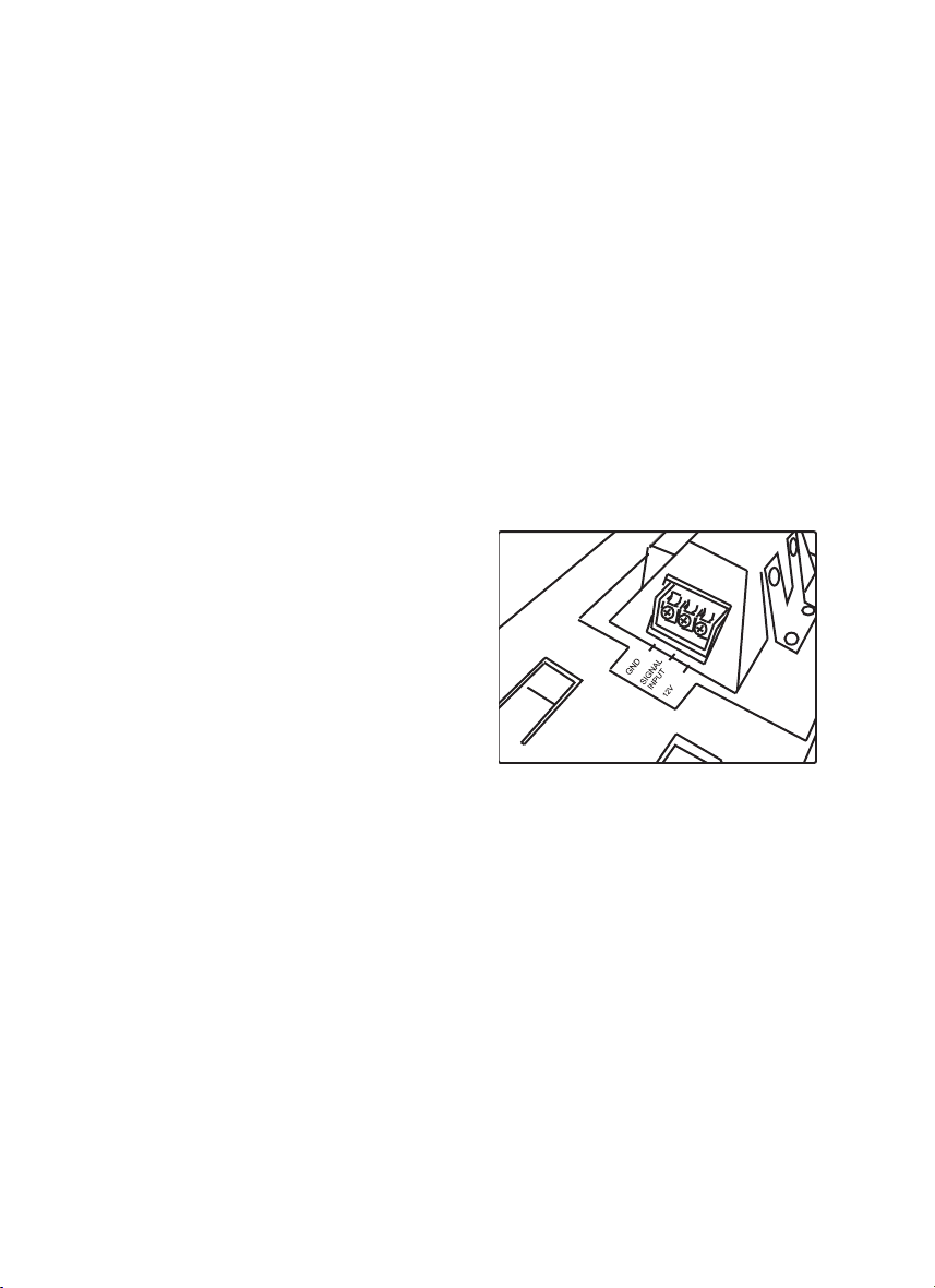
There are three (3) connecting tabs
at the rear right side of the display.
They are labeled “GND” which is
where you would connect your
chassis / DC GND wire. The next is
labeled “signal input”; this is where
you would connect the (+ side) of
the signal which would drive the
display – this can either be; music
from your head-unit, the audio
output from your DVD player or the
audio from your MP-3 player and etc.; basically, as long as the audio signal
is of “line level” type, it would be compatible. The next terminal is labeled
“+ 12V” and this is where you would connect the 12 volt source from your
car or AC adapter (obviously + / positive side).
Make sure that these wires are properly secured and / or that you fully
understand their functions before continuing with the installation.
After you’ve done that, the next step is to decide on a particular mounting
style; as you can see, the choices are table-top (mounting stand provided)
and panel-mount. If you choose panel mounting, use the snap-ring
(provided) as a template to mark the cut-out area where you would
mount the display. Please avoid installing the display in high temperature
areas, where temperatures can exceed 50 deg. C / 122 deg. F.

If you prefer to use the display in locations other than your vehicle, simply
purchase and AC adapter which provides a regulated 12 volt output @
500 milliamps and follow the same steps as above.
ELECTRICAL CONNECTIONS & Specications:
• Connect the negative (-) side of the signal source to the same point
(GND) as the DC power source or negative power terminal. Note
that if the signal source and the PL-1 share a common power
source, (example in-car installation) there is no need for this
connection (one or two wires on this tab)
• Connect the positive (+/signal carrying) side of the source signal to
the tab marked “signal input” (one wire to this tab).
• Lastly, connect the + 12 volt wire (AC adapter or battery voltage) to
the terminal / tab marked B+ / + 12V (one wire to this tab).
• Minimum input (from signal source) 25~50 mv @ 10k ohms
-
Output form DVD,CD,MP3 etc.
+
GND
INPUT
+12V
B+ / +12V
SIGNAL
B- / -12V
AC adapter or battery voltage

Use & function:
The three (3) position switch at the front left portion of the display,
provides you with 3 selections: (C) an “o” function (B) a standard input,
via signal input terminal and (A) microphone input.
The microphone is located at the front right side. Please do not block
the microphone if you are using it as the source of input to drive the
display.
The display is intended to create lightning-like pulses, which are
in-step with the sound source you have chosen (music or microphone).
If the veins appear too heavy or concentrated, lower the input signal,
as continued use at this level, can cause premature damage to the unit.
WWW.POWERACOUSTIK.COM
 Loading...