

Page 1
PDR-340/PDR-340T
Flip-down/Detachable 3.4” Monitor
MP3/MP4 Player
AM/FM Radio
Built-in TV tuner (only for PDR-340T model)
Owner’s Manual
Take the time to read through this owner’s manual.
Familiarity with installation and operation procedures will help you obtain the best
Performance from your new device.
Page 2

Important Safeguards
z Using the device at temperature below -10 may cause the breakage of the device. ℃
BEFORE USING PLEASE HEAT UP THE PASSENGER COMPARTMENT TO THE
RECOMMENDED TEMPERATURE!
z Read carefully through this manual to familiarize you with this high-quality sound system.
z Disconnect the vehicle's negative battery terminal while mounting and connecting the unit.
z When replacing the fuse, be sure to use one with an identical amperage rating. Using a fuse
with a higher amperage rating may cause serious damage to the unit.
z Make sure that pins or other foreign objects do not get inside the unit; they may cause
malfunctions, or create safety hazards such as electrical shock or laser beam exposure.
z If you have parked the car for a long time in hot or cold weather, wait until the temperature in
the car becomes normal before operating the unit.
z DO NOT open covers and do not repair yourself. Consult the dealer or an experienced
technician for help.
z Make sure you disconnect the power supply and aerial if you will not use the system for a long
period or during a thunderstorm.
z Make sure you disconnect the power supply if the system appears to be working incorrectly,
(For example: making unusual sounds, smelling strange, emitting smokes from inside or
liquid having gotten inside it) Have a qualified technician check the system.
z The unit is designed for negative terminal of the battery, which is connected to the vehicle
metal. Please confirm it before installation.
z Do not allow the speaker wires to be shorted together when the unit is switched on. Otherwise
it may overload or burn out the power amplifier.
z Do not install the detachable panel before connecting the wire.
z Don't remove the detachable panel when encoding.
2
Page 3

Contents
Important Safeguards...............................................................................................................2
Contents...................................................................................................................................3
Accessories..............................................................................................................................4
Installation/Un-Installation........................................................................................................5
Wiring Connections..................................................................................................................6
Front panel...............................................................................................................................8
Inner panel...............................................................................................................................8
Remote control.........................................................................................................................9
Remove battery........................................................................................................................9
Main Menu.............................................................................................................................10
General Operation .................................................................................................................10
Radio operation......................................................................................................................13
USB/SD/MMC Operation .......................................................................................................14
TV Opeartion(only for PDR-340T model)...............................................................................15
Anti-theft system....................................................................................................................16
Troubleshooting guide ...........................................................................................................17
Specification...........................................................................................................................18
3
Page 4
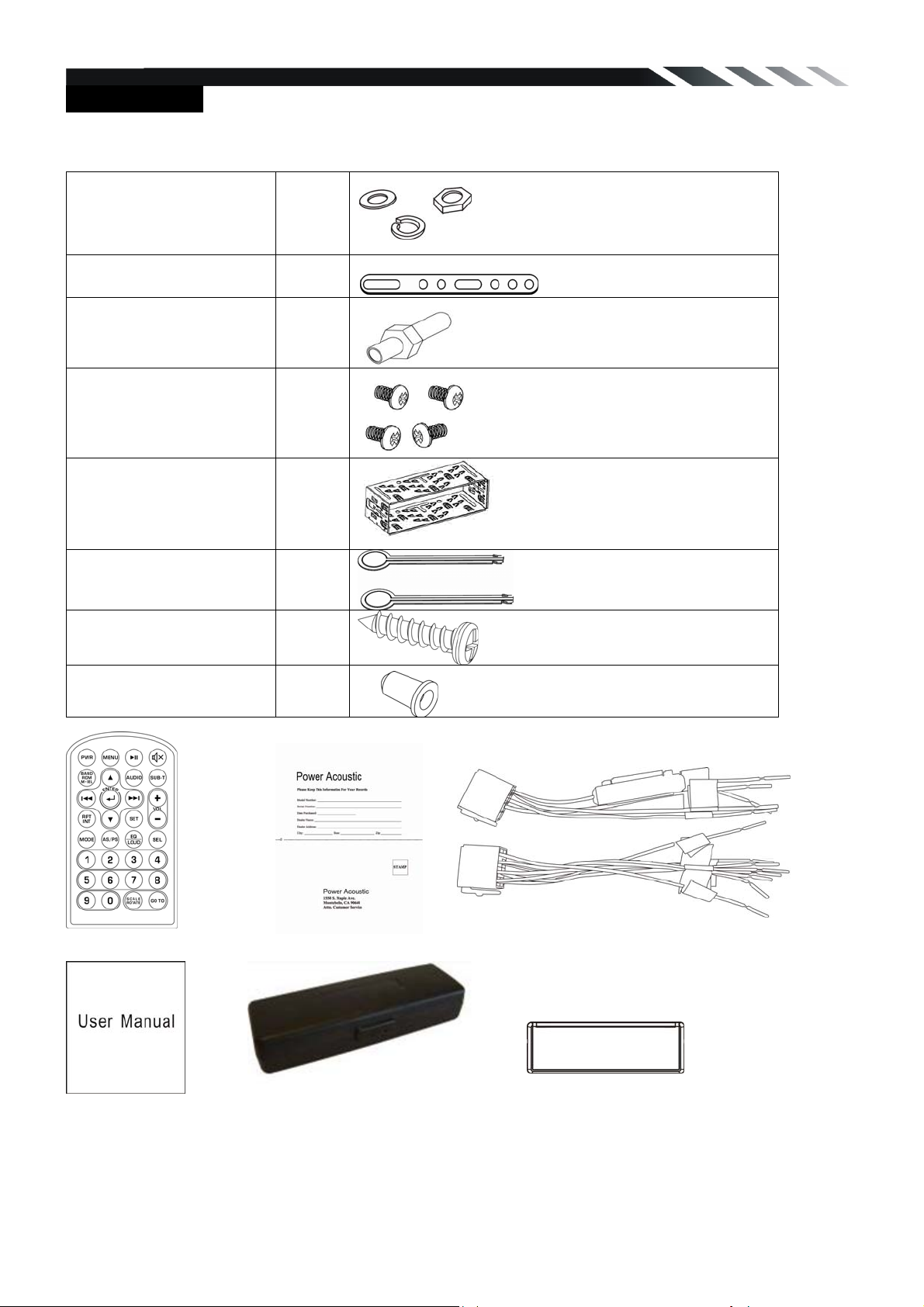
Accessories
Package contains the following accessories for installation and operation of the unit.
(1) Washer, Spring
Washer, M5 Nut
1 each
(2) Mounting Strap 1
(3) Bolt 5*20 1
(4) Screw 5*6 4
(5) Mounting Collar 1
(6) Release Key 2
(7) Screw 5*20 1
(8) Rubber Cushion 1
Remote Control Warranty card ISO cable
User Manual 1x front panel protection case Trim ring
Noted:
Product image may vary from the actual delivery
4
Page 5
Installation/Un-Installation
First complete the electrical connections, and then check them for correctness.
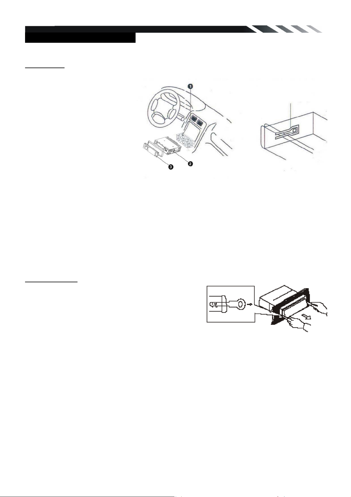
Installation
This unit can be installed in any
dashboard having an opening as
shown on the picture. The
dashboard should be 4.75 – 5.56
mm thick in order to be able to
support the unit.
1. Insert mounting collar into the
dashboard, and bend the
mounting tabs out with a
screwdriver.
Make sure that lock lever(※)is
flush with the mounting collar (not
projecting outward).
2. Secure the rear of the unit.
After fixing mounting bolt and power connector, fix the rear of the unit to the car body by rubber
cushion.
3. Insert trim plate.
When you prepare to insert trim plate, please check its direction. Once it was up side down, it
cannot be fixed.
Un-installation
Remove Trim Ring and insert Release Keys into left and
right side-end holes as shown in below picture and pull
the unit out of the dashboard.
5
Lock lever(※)
Page 6
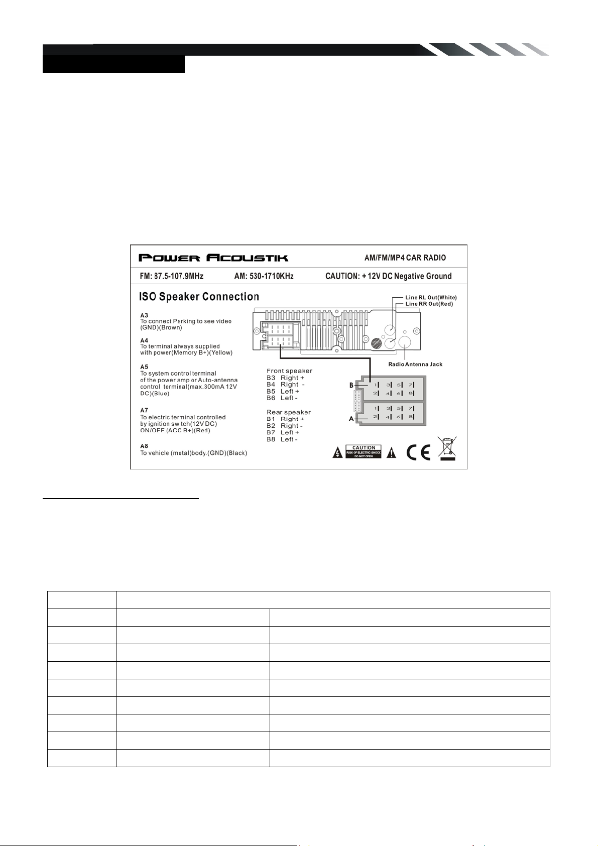
Wiring Connections
Make sure you have good chassis ground. A good ground connection will eliminate most
electrical noise problems. A good chassis ground requires a tight connection to the vehicle’s
metal chassis. The area around the ground connection should be clean, bare metal without rust,
paint, plastic, dust, or dirt for a good electrical connection.
Caution: Do not interchange the connection of the wiring!!!
For some car models you may need to modify wiring of the supplied power cord. Contact your
authorized car dealer before installing this unit.
(Only for PDR-340)
Using the ISO Connector
1. If your car is equipped with the ISO connector, then connect the ISO connectors as illustrated.
2. For connections without the ISO connectors, check the wiring in the vehicle carefully before
connecting, incorrect connection may cause serious damage to this unit.
3. Cut the connector; connect the colored leads of the power cord to the car battery as shown in
the color code table below for speaker and power cable connections.
Location Function
1 Rear Right(+)---Purple
2 Rear Right(-)---Purple/Black Stripe
3
4
5
6 Front Left(-)---White/Black Stripe
7
Connector A Connector B
Parking (GND)---Brown
Battery 12V (+)---Yellow
Auto Antenna---Blue
ACC(+)---Red
Front Right(+)---Grey
Front Right(-)---Grey/Black Stripe
Front Left(+)---White
Rear Left(+)---Green
8
Ground---Black
Rear Left(-)---Green/Black Stripe
6
Page 7

(Only for PDR-340T)
Using the ISO Connector
1. If your car is equipped with the ISO connector, then connect the ISO connectors as illustrated.
2. For connections without the ISO connectors, check the wiring in the vehicle carefully before
connecting, incorrect connection may cause serious damage to this unit.
3. Cut the connector; connect the colored leads of the power cord to the car battery as shown in
the color code table below for speaker and power cable connections.
Location Function
1 Rear Right(+)---Purple
2 Rear Camera---Yellow Rear Right(-)---Purple/Black Stripe
3
4
5
6 Front Left(-)---White/Black Stripe
7
8
Connector A Connector B
Parking (GND)---Brown
Battery 12V (+)---Yellow
Auto Antenna---Blue
ACC(+)---Red
Ground---Black
Front Right(+)---Grey
Front Right(-)---Grey/Black Stripe
Front Left(+)---White
Rear Left(+)---Green
Rear Left(-)---Green/Black Stripe
7
Page 8

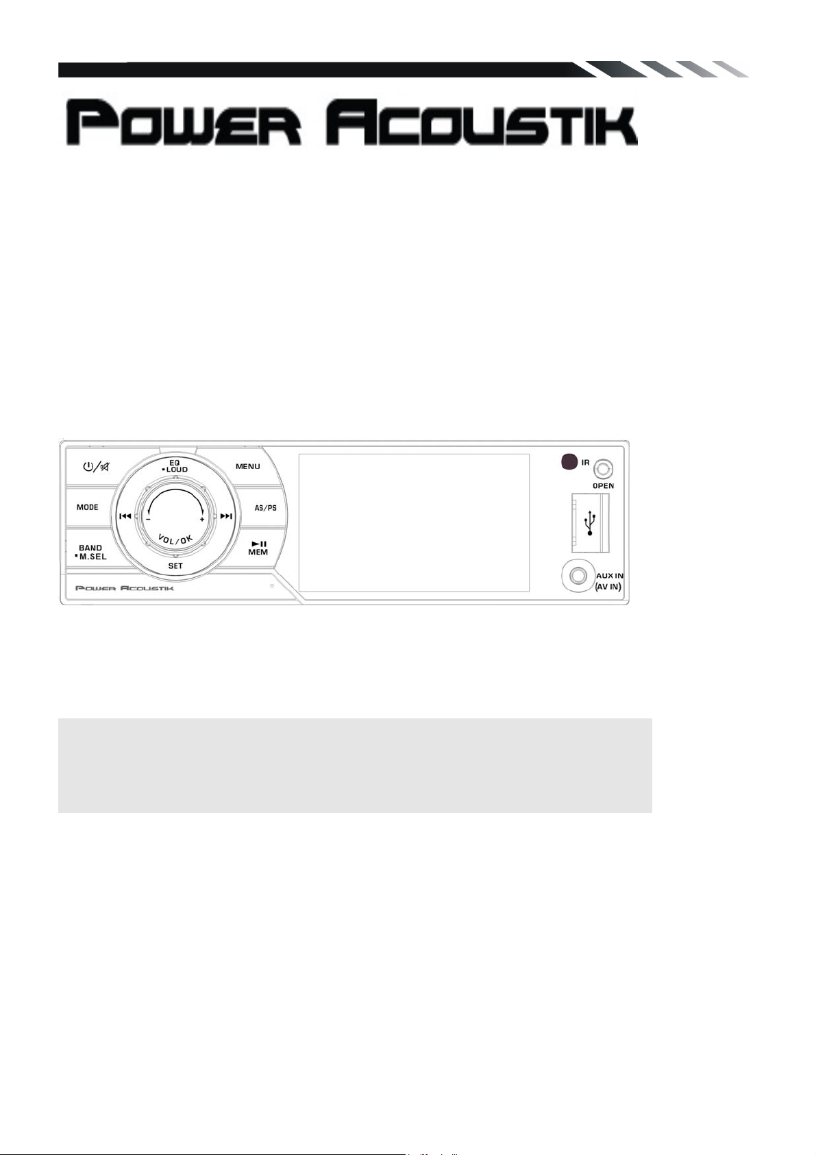
Front panel
1) Power /Mute button
2) Mode button
3) Volume/OK button
4)
5) SET button
6) Previous / Reverse button
7) EQ /LOUD button
8) Next / Forward button
BAND / Media select /Radom button
9) MENU button
10) AS/PS button
11) Play/Pause, Memory button
12) LCD Screen
13) IR sensor
14) OPEN button
15) USB slot
16)
AUX IN jack/ AV IN jack(optional)
Inner panel
17) SD/MMC card slot
18) Reset button
19) Anti-Theft LED flash
NOTE:When turn off the power, the unit will switch to standby mode unless cut the ACC power.
The power light will continue lighting.
8
Page 9

Remote control
1: MENU
2: POWER
3: UP
4: BAND/M.SEL/RDM
5: ENTER
6: LEFT/SEEK-/FAST BACKWARD
7: DOWN
8: REPEAT/INT
9: AS/PS
10: MODE
11: DIGIT NUMBER
12: PLAY/PAUSE
13: MUTE
14: AUDIO
15: SUBTITLE
16: RIGHT/SEEK+/FAST FORWARD
17: VOLUME PLUS
18: SET
19: VOLUME MINUS
20: EQ/LOUD
21: SEL
22: SCALE/ROTATE
23:GO TO
Remove battery
Note:
The distance may vary according to the brightness of ambient light.
If the remote is not used for an extended period of time, remove the battery to prevent possible
damage from battery leakage and corrosion.
Do not place any objects between the remote
control unit and the sensor on the unit.
Do not drop the remote control onto the floor; it
will damage it beyond repair.
Do not use the remote control unit, while
simultaneously operating the remote control unit of any other equipment; they may interfere
resulting in improper operation.
The battery normally last for about one year although depending how often the remote control
is used. If the remote control unit isn’t working even when it is operated near the unit, replace
the battery with a new battery of the same make and use only a lithium cell battery type:
CR2025 (3V).
Dispose empty batteries in accordance with your local governmental regulations.
Do not short-circuit, disassemble, heat or dispose of fire or flames the battery.
Keep the battery out of reach of children, should the battery be swallowed, immediately consult
a doctor.
9
Page 10

Main Menu
The best way to discover the program is to explore each screen in detail, and to find out how to
move from one to another. Read this chapter for a guided tour.
Unit starts by displaying the Main menu.
This is the root of the screen hierarchy, you can simply take knowledge of the features.
General Operation
Reset the unit
Operating the unit for the first time or after replacing the car battery, you must reset the unit.
Press OPEN button on the panel to open the panel and press RESET button to restore the unit to
its original factory settings.
Power on or off
Press any button (except open button) to turn on the unit.
Long press POWER button on front panel or press power button on the RC to power off the unit..
Mode setting
Press the MODE button repeatedly to switch between inputs:
RADIO→USB→SD→AUX IN/AV IN→RADIO
(* available only if there is media device in SD, USB slot connection is OK.)
Volume/OK
Adjust the volume level by turning the VOL knob on the panel clockwise to increase or
counterclockwise to decrease or pressing VOL+ or /VOL- on the RC to increase or decrease the
volume.
In any mode, rotate VOL knob to select the file you want to playback, press the OK button to enter
the next menu.
In Mp3 mode, when playing the music, press the OK button on the front panel, the music will
start from the beginning.
In Photo mode, when playing the photo, press the OK button on the front panel to enter the
photo setup menu.
10
Page 11

In Video mode, when playing the video, press the OK button on the front panel, you will see the
track number and running time on the screen
Sound Adjustments
Press the SEL button on the RC to select the audio settings consisting of following items:
EQ: Select the digital sound effect USER→FLAT→CLASSIC→POP→ROCK
BASS: Bass up/down.
TREBLE: Treble up/down.
BALANCE: Left/right Balance control.
FADER: Front/rear Fader control.
LOUDNESS: Set the loudness on or off.
BEEP: Keypad sound setting.
Rotate Volume knob on the front panel or press up/down arrow on the RC to select any items and
then press OK button on the panel or Enter button on the RC to confirm the item.
Rotate Volume knob or press LEFT/RIGHT buttons on the RC to adjust the audio setting. Press OK
button on the panel or Enter button on the RC to confirm and again press SEL button return to
current mode.
Note:
If the unit is turned off, all the settings of each mode will be saved.
If cutting off battery power or resetting the unit, all the settings will return to factory default
settings.
Mute function
Press POWER/MUTE button on the panel or MUTE button on the RC to turn the sound off. Press it
again to resume the volume.
Loudness
Long press EQ/LOUD button on the RC or front panel to set loudness on or off.
EQ
Press the EQ button on the panel to choose sound effect in the sequence of USER→FLAT→
CLASSIC→POP→ROCK.
Menu
Press MENU button on the front panel or the RC to return to previous menu.
Setup
Press SET button on the RC or front panel, or SET icon on the main menu to go to setup pages.
1) Rotate Volume knob on the front panel or press up/down arrow on the RC to select any items
and then press OK button on the panel or ENTER button on the RC to confirm the item
2) Rotate Volume knob or press LEFT/RIGHT buttons on the RC to adjust the audio setting. Press
OK button on the panel or Enter button on the RC to confirm.
3)Press SET button on the RC or front panel again return to current mode.
Sound
EQ: select the digital sound effect.
Bass: bass up/down.
Treble: treble up/down.
Balance: Left/right Balance control.
Fader: Front/rear Fader control.
11
Page 12

Display
General
LONDNESS: Selecting loudness ON will
emphasize the low frequency output.
BEEP: Keypad sound setting.
Bright: set the LCD screen brightness up or
down
Contrast: set contrast up or down
Saturation: set saturation up or down
Radio
System information
Clock hour: select 12-hour or 24-hour clock
display mode.
Clock set: Press number buttons to input the
current time.
Area: Select radio broadcasting area.
Stereo: Select stereo on or off.
Product Info:You can view detail system
information including serial number of the
software
Default Set:return to factory default setting or
not
AUX IN
Connect an optional AUX cable to your external AUX device, then press the MODE button to
switch to the AUX mode.
12
Page 13

AV IN (OPTIONAL)
Connect an optional AV cable to your external AV device (such as a video camera), then press the
MODE button to switch to the AV mode. Note: If there is no external video input, the TFT displays
“NO SIGNAL”.
Parking
When the car is stopped and the parking brake is working, the screen can display the video image,
and otherwise the screen display warning information.
Radio operation
Band selection
In Radio mode, press BAND button on the RC or front panel to select your band of choice in the
following sequence:
FM 1 FM 2 FM 3 AM1 AM2
Manual tuning
To find a station, select a band first, then press and hold / buttons on the RC until Manual
appear on the display. Then press repeatedly these buttons to search for the needed frequency
upward or downward.
Auto tuning
To find a station, select a band first, then press / buttons on the panel or press /
buttons on the RC, the automatic search will start downward or upward. It will stop when a station
is found.
Select a station
Repeatedly press / buttons on the panel to select a present station downward or upward.
Or press digital number (1-6) on the RC to select any present station.
Preset scan
In tuner mode, press the AS/PS on the panel or RC to scan the preset memorized station, each
preset scan for 5 seconds. Press again to stop operation.
Auto store
In tuner mode, Press the AS/PS on the panel or RC and hold for 2 seconds to store radio stations
with the best reception to the preset number automatically.
Manual store
In tuner mode, long press the number 1-6 buttons on the RC after you find the station you desired.
The station will preset to the corresponding number.
In tuner mode, long press the MEM button on the front panel after you find the station you desired,
then rotate the VOL knob to select the number 1-6 on the radio interface, press the VOL/OK button
on the front panel to confirm. The station will preset to the corresponding number.
13
Page 14

USB/SD/MMC Operation
USB Flash Memory
To play MP3/ MP4/ WMA files from a USB flash memory, insert a USB/iPod flash memory into the
USB port on the right side of the unit. The unit will play automatically MP3/MP4/ WMA/JPEG files.
Or repeatedly press the MODE button to select USB mode.
SD/MMC Card
To play MP3/ MP4/ WMA/JPEG files on a SD/MMC card, insert the card into the card slot (you
should press the Open button on the panel to flip down front panel and insert the SD/MMC card
into card slot.) The unit will play automatically MP3/MP4/ WMA/JPEG files. Or repeatedly press the
MODE button to select SD mode.
Play/Pause
In Multimedia mode, press Play/Pause button on the RC or front panel to pause playback. Press
again to resume playback.
Select track
Press the M.SEL button on the front panel or RC to select the playback mode: MUSIC MODE
PHOTO MODE VIDEO MODE. Then press the UP/DOWN button on the RC, also you can
rotate the VOL knob or press the or on the front panel to select the file you desired to
playback. Press ENTER button on the front panel or RC to enter the next menu, press the MENU
button on the front panel to turn to previous menu. Press the MENU button on the RC to back to
main menu.
During playback press SEEK- or SEEK+ on the RC or front panel to play the previous or
next track. You can play the tracks by pressing Play/Pause button. Press number button (0-9) on
the RC to select the desired track and then press ENTER button on the RC to confirm playback.
Random playback
In Media file mode, long press RDM button on the RC or BAND button on the front panel to set
random playback on or off.
Fast backward/forward
During playback press and hold repeatedly SEEK- or SEEK+ on the RC or the panel to
activate fast backward or forward playing. With each pressing, the playback speed will increase.
While fast playback, press Play/Pause button on the RC to resume normal speed.
When fast backward/forward playback reaches the previous or next track, the unit will resume
normal payback.
GOTO
During playback, press the GOTO button on the RC to select the playback time of the track or
chapter. Input the start time you want the track or chapter to start. Press or button on the
RC to select the time you want to set, such as, hour: minute: second. Press the DIGITAL NUMBER
button or UP/DOWN arrow button on the RC to set the time. Press ENTER to confirm. The track or
chapter will start from the time you set.
Repeat playback
During Mp3 or Video file playback, press RPT button on the RC repeatedly for repeat playing in
different modes: Repeat one, and repeat all.
Scale/Rotate
During Photo file playback, press it on the RC in photo mode to rotate the image clockwise by 90
degrees. How many times the button is pressed, the image will be rotated the corresponding times.
During Video file playback, press it on the RC in Video mode to set the display ratio: 4:3 16:9
Full Screen.
14
Page 15

Select audio language
During Video file playback, press AUIO button on the RC repeatedly to select the audio language
to listen. (Available only with the Video file that support multi-language playback).
Select subtitle language
If your Video file supports multi-language subtitle, press SUB-T button on the RC repeatedly to
switch among the supported language.
Photo Adjustments
During Photo file playback, press the ENTER button on the RC or OK button on the front panel to
enter the photo set menu. Press the or button on the RC to select the item you want to set,
such as ZOOM/Rotate/Slideshow/Interval/Scale. Press the UP/DOWN arrow button on the panel to
select the selection you want set in the item menu,press ENTER button on the RC or front panel to
confirm. Zoom selection:×1 ×2 ×3 ×4.Rotate selection:90° 180° 270° 0°. Slideshow:
Fade In Fade Out, Persian Blinds H, Persian Blinds V, Slide up, Slide down, etc.
Interval selection: Fast, Middle, Slow. Scale selection: Auto, Original, Crop, Stretch.
TV Opeartion(only for PDR-340T model)
1. Connect TV antenna, and then press MODE button to select TV mode.
2. In TV mode, press the Play/pause button once to enter TV menu setting.
3. Press the / buttons on the remote control or turning the knob clockwise or counterclockwise
on front panel to select one of the setup pages: Auto program => Manual program.
4. Press VOL button on front panel or ENTER button on remote control to enter the page.
5. Press the / buttons to select the setting.
6. Press VOL button on front panel or ENTER button on remote control again to confirm, press
Play/pause to return to settings list.
TV MENU
Press the MEM button to enter the setup menu of TV.
Auto program (Auto seek mode)
z
System
Select the menu item is to set TV system: NTSC=>PAL=>SECAM, press ENTER button on
remote.
z Audio
Select this menu item is to set the TV sound system:
1) When system setting PAL, TV sound system can set B/G=>I=>D/K=>/M/N, press ENTER on
remote.
2) When system setting SECAM, TV sound system can set B/G=>I=>D/K, press ENTER on
remote.
3) When system setting NTSC, M/N sound system can be selected only.
z
Search
Select this menu item is to start searching and storing stations automatically.
15
Page 16

Manual program (manual seek mode)
Storage
Select this menu item is to set the storage number.
z System
Select this menu item is to set TV system: SECAM => NTSC =>PAL, press NTER button on the
remote control to select.
z
Audio
Select this menu item is to set the TV sound system:
1) When system settings PAL, press ENTER on remote or tap the screen button to select TV
sound system: D/K=>M/N=> B/G=> I.
2) When system setting SECAM, TV sound system B/G=>I=>D/K.
3) When system setting NTSC, M/N sound system can be selected only.
Channel
Select this menu item is to set your desired searching channel, press / button on the RC
to select one, or press
z
Fine
Select this menu item is to fine TV tuning and sound until it achieves the best quality, press /
button on remote to adjust.
z Memory
Select memory on or off is to set whether memory the searched station or not, press
ENTER on remote control to select.
/ icon to select channel.
Anti-theft system
Remove the panel
1. Press the PWR button to turn the power off.
2. Press OPEN button to detach the panel.
3. Pull the panel out.
4. Place the panel into the case and take it with you when you leave the car.
Remove the unit
1. Remove the panel and the trim plate.
2. Insert both T-Keys into hole on the front of the set until they lock.
3. Pull out the unit.
NOTE:
The source unit will turn off if the control panel is open longer than 60 seconds.
The LED light on the inner panel will twinkle in red when the ACC power is cut off.
16
Page 17

Troubleshooting guide
Symptom Cause Solution
If the power supply is properly connected
General
No power
The car ignition is not on.
The fuse is blown.
to the car accessory switch the ignition
key to “ACC”.
Replace the fuse.
No sound
The operation
keys do not
work.
The radio does
not work; the
radio station
automatic
selection does
not work.
Volume is in minimum.
Wiring is not properly
connected.
The built-in microcomputer
is not operating properly
due to noise.
Front panel is not properly
fixed into its place.
The antenna cable is not
connected the signals are
too weak.
Adjust volume to a desired level.
Check wiring connection.
Press the RESET button.
Reinstall the front panel.
Insert the antenna cable firmly select a
station manually.
17
Page 18

Specification
General
Power supply: 12 V DC
Current consumption: Max. 10 A
Maximum power output: 52W x 4 channels (Max.)
Compatible formats: MP3/MP4/WMA/ JPEG/RMVB
Dimensions (W x D x H) /
weight:
ESP function: 40 sec. for Audio CD, 120 sec. for MP3
Working temperature
range:
TFT display
Screen size: 3.4 inch
Resolution: 240*3*400 dot
Aspect ratio: 4:3/16:9
Contrast ratio: 400:1
Brightness: 250 cd/m2
178 x 175 x 50 mm / 1.8 kg
-10℃ - +60℃
FM Stereo Radio
Frequency range(EUROPE AREA): 87.5 – 108MHz(Step 50KHz)
Frequency range(ASIA AREA) 87.5 – 108MHz(Step 100MHz)
Frequency range(U.S.A AREA) 87.5 – 107.9MHz(Step 200KHz)
Preset memory stations: 18
AM/MW Radio
Frequency range(EUROPE AREA): 522kHz - 1620 KHz(Step 9KHz)
Frequency range(AISA AREA) 531kHz - 1602 KHz(Step 9KHz)
Frequency range(U.S.A AREA) 530kHz - 1710 KHz(Step 10KHz)
Preset memory stations: 12
Audio specification
Maximum output: 1.5 Vrms (+/- 3 dB)
Frequency response: 20 Hz - 20 KHz
S/N ratio(A-vtd): 68 dB
DSP sound effect:
Line out
USER→FLAT→CLASSIC→POP→ROCK
Line outs: 2 channel RCA line-out
Specifications are subject to change without notice. Mass and dimension are approximate.
18
 Loading...