

Page 1
POWERED SUBWOOFER SYSTEM
Page 2
POWER ACUOUSTIK
YOUR NEW SUBWOOFER..........
* RCA INPUT/HIGH LEVEL INPUT
* P.W.M MOSFET POWER SUPPLY
* SOFT DELYED REMOTE TURN-ON
* DUAL COLOR INDICATOR L.E.D (POWER/GREEN & PROTECTION/RED)
* REMOTE CONTROL FOR SUBWOOFER LEVEL
* CONTROL: GAIN, PHASE, LPF, BASS BOOST
* PROTECTION CIRCUIT: THERMAL PROTECTION CIRCUIT
SHORT PROTECTION CIRCUIT
OVERLOAD PROTECTION CIRCUIT
* AUTO COOLING
Page 3
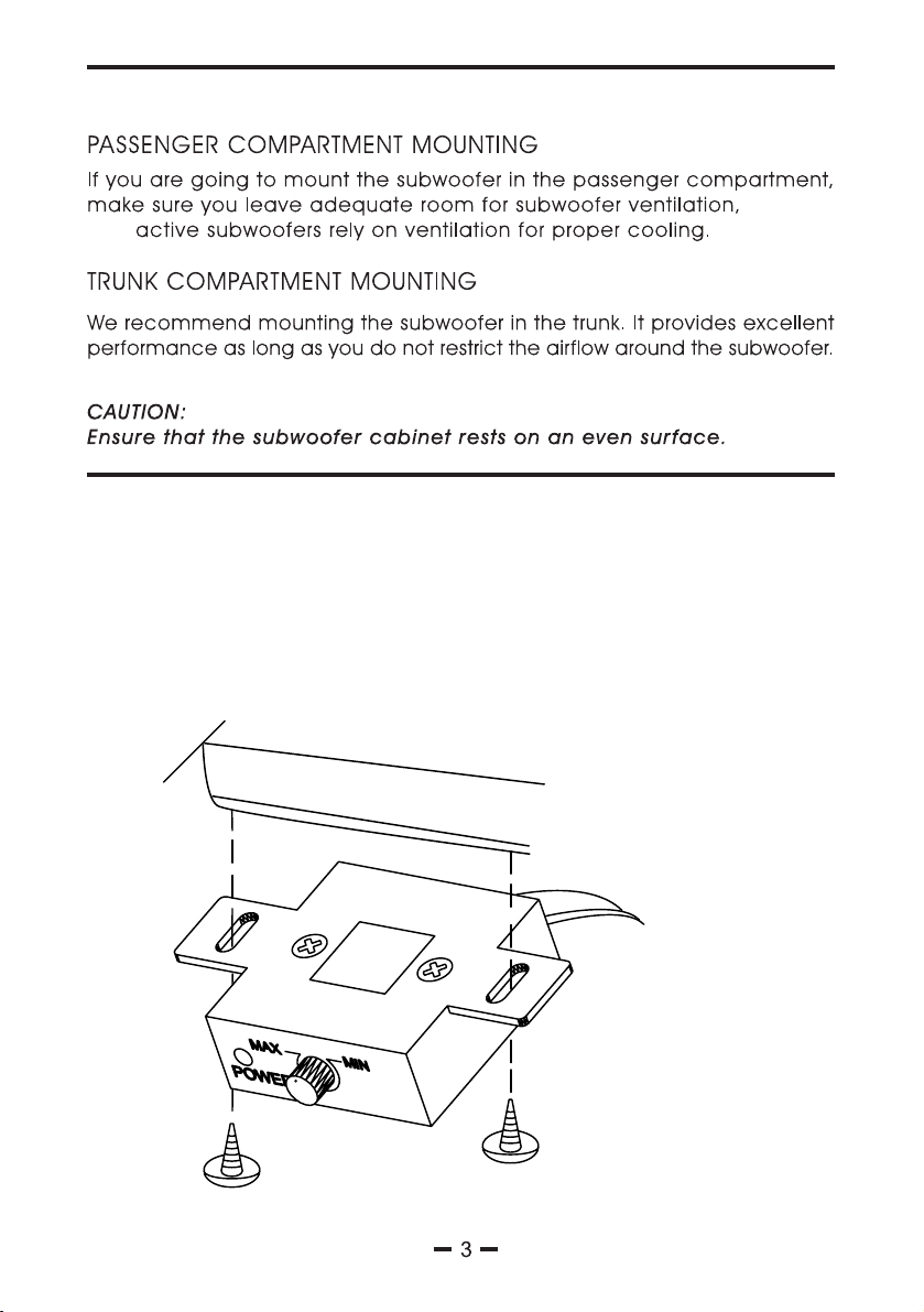
SUBWOOFER MOUNTING LOCATION
This
INSTALLING THE REMOTE
Select a mounting location that allows easy access to the control while driving.
Using the subwoofer level control(remote) as a template, mark and drill holes
in the mounting surface.
UNDER DECK MOUNTING (Suggestion of the remote placement)
Page 4

CONNECTION AND OPERATION
G H
I J
A
B
25A
EFDC
A
POWER INPUT TERMINAL (CONNECTING THE POWER Fig. 1)
Page 5

CONNECTING THE POWER (Fig.1)
Vehicle's chassis ground
POWER INPUT
To Power antenna
( )
B
FUSE
25A
The amplifier is equipped with a plug-in auto fuse protecting set against
fault conditions. Do not use a fuse with a higher value and never bridge
the fuse over.
C
L.E.D
The L.E.D is a dual color indicator, when the +12v and REM +12 volt
power both switch on, The L.E.D illuminated green. this means that
the amplifier begin to work. if L.E.D illuminated red colour, this means
the amplifier is shut down from protecting circuit(thermal protection
& short protection & overload protection).
Page 6

D
REMOTE (CONNECTING THE SUBWOOFER TO THE REMOTE Fig. 2)
Use remote wire(accessory) connect "REMOTE SOCKET" to the
remote (accessory), the remote is for subwoofer level control.
Fig. 2 Connecting the subwoofer to remote
25A
E
LINE IN(LOW LEVEL INPUT)
L
Use a pair of shielded stereo audio cable with RCA
LINE IN
type jack connect your receiver's "LOW LEVEL OUT"
to the RCA input
R
Rear view of remote controller
Page 7

F
HI INPUT( HIGH LEVEL INPUT)
1 2 3
54
HI INPUT CONNECTOR WIRE(ACCESSORY)
1
1= White, Channel L2=Black, GND
3=White/Black, Channel L+
4=Grey,
Channel R-
5=Grey/Black, Channel R+
G
PHASE
The PHASE switch is used for changing woofer phase, set switch from
o o
"0 " to "180 ", a phase shift of 180 degrees.
H
LPF
White L-
Grey R-
4
Grey/Black R+
2
Black, GND
3
White/Black L+
5
The low-pass crossover is continuously variable from 50Hz to 150Hz
I
BASS BOOST
Varies from 0dB to 12dB of boost. Frequency adjustment control for
bass control filter.
J
GAIN
The "GAIN" control is subwoofer input level control, the input level control should
match the output of your radio. After the installion is complete, make sure the input level
control is turned down all the way(MIN). Play a tape or CD and turn volume up slowly until
you just start to hear distortion, now back the volume down just a bit. On the subwoofer,
slowly turn up the input level control(clockwise) until you start to hear distortion and back it
down a bit, Now your radio and subwoofer leves are matched.
ACESSORY LIST PER CARTON BOX
1. Remote..........1pc
2. Remote wire..........5m
3. High level input connector with wire..........1pc
4. Mounting magic tape.......2 sets
5. Mountint bracket & Screw..........1 set
6. manual..........1pc
7
Page 8

ITEM
800W
<0.4%
>90%
20Hz TO 150Hz
INPUT SENSITIVITY
LPF
BASS BOOST
DIMENSIONS(L x W x H)
NET WEIGHT
LOW
HIGH
110mV
0.5V
50Hz -150Hz Adjustable
0dB-12dB
25A
10 INCH
400 x 240 x310 mm
8.8kg
Note: SPECIFICATIONS ARE SUBJECT TO CHANGE WITHOUT NOTICE.
SOUND
DISTORTED
Is volume minimum?
Input level control
adjusted too high
Adjust input level control
8
 Loading...