

Powell Power/Vac Instruction Bulletin

Powered by Safety
®
Instruction Bulletin - 01.4IB.67000
Power/Vac® Metal-Clad Switchgear
5kV & 15kV
20kA, 25kA, 31.5kA, 40kA, 50kA, & 63kA
1200A, 2000A, 3000A, 3500A, & 4000A FC

Power/Vac® Metal-Clad Switchgear 5kV & 15kV
Contact Information
Powell Electrical Systems, Inc.
powellind.com
info@powellind.com
01.4IB.67000
Service Division
7232 Airport Blvd.
Houston, Texas 77061
Tel: 1.800.480.7273
Powered by Safety
®
01.4IB.67000
DANGER
WARNING
CAUTION
CAUTION
NOTICE
Signal Words
As stated in ANSI Z535.4-2007, the signal word is
a word that calls attention to the safety sign and
designates a degree or level of hazard seriousness.
The signal words for product safety signs are
“Danger”, “Warning”, “Caution” and “Notice”.
These words are defined as:
!
DANGER indicates an imminently hazardous
situation which, if not avoided, will result in
death or serious injury.
!
WARNING indicates a potentially hazardous
situation which, if not avoided, could result in
death or serious injury.
Qualified Person
For the purposes of this manual, a qualified
person, as stated in NFPA 70E®, is one who has
skills and knowledge related to the construction
and operation of the electrical equipment and
installations and has received safety training to
recognize and avoid the hazards involved. In
addition to the above qualifications, one must also
be:
1. trained and authorized to energize,
deenergize, clear, ground, and tag circuits
and equipment in accordance with
established safety practices.
2. trained in the proper care and use of
personal protective equipment (PPE)
such as rubber gloves, hard hat, safety
glasses or face shields, flash clothing, etc.,
in accordance with established safety
practices.
3. trained in rendering first aid if necessary.
!
CAUTION, used with the safety alert symbol,
indicates a hazardous situation which, if not
avoided, could result in minor or moderate
injury.
CAUTION, used without the safety alert
symbol, is used to address practices not
related to personal injury.
NOTICE is used to address practices not related
to personal injury.
Powered by Safety
®

Power/Vac® Metal-Clad Switchgear 5kV & 15kV
01.4IB.67000
Contents
Ch 1 General Information ................................................................................................ 1
A. Scope ...............................................................................................................................................................2
B. purpoSe ............................................................................................................................................................2
c. InStructIon BulletInS AvAIlABle electronIcAlly ....................................................................................................2
Ch 2 Safety .......................................................................................................................3
A. SAfe Work condItIon .........................................................................................................................................3
B. SAfety GuIdelIneS ...............................................................................................................................................3
c. GenerAl ............................................................................................................................................................4
d. SpecIfIc .............................................................................................................................................................4
e. SAfety lABelS ....................................................................................................................................................4
Ch 3 Equipment Description ............................................................................................ 5
A. GenerAl ............................................................................................................................................................5
B. prImAry compArtment ........................................................................................................................................5
c. SecondAry compArtment ....................................................................................................................................9
d. BreAker removABle element ...............................................................................................................................9
e. BreAker lIft truck .......................................................................................................................................... 10
f. rAtInGS .......................................................................................................................................................... 10
G. lIGhtInG ImpulSe WIthStAnd (BIl) .................................................................................................................... 10
h. cIrcuIt BreAker rAckInG mechAnISm ................................................................................................................. 10
I. remote rAckInG .............................................................................................................................................. 11
J. prImAry dISconnect devIceS ............................................................................................................................ 11
k. BuS compArtment ........................................................................................................................................... 12
l. current trAnSformer compArtment ................................................................................................................. 12
m. prImAry termInAtIon SpAce .............................................................................................................................. 12
n. voltAGe trAnSformerS .................................................................................................................................... 13
o. current-lImItInG fuSeS And control poWer trAnSformer .................................................................................. 13
p. dummy removABle element (type pvd) ........................................................................................................... 13
Q. Ground And teSt devIce .................................................................................................................................. 14
4
Powered by Safety
®

01.4IB.67000
Contents
Ch 4 Installation ............................................................................................................. 15
A. GenerAl ......................................................................................................................................................... 15
B. receIvInG ........................................................................................................................................................ 15
c. hAndlInG ....................................................................................................................................................... 15
d. StorAGe ......................................................................................................................................................... 16
e. poSItIonInG the metAl-clAd SWItchGeAr ........................................................................................................... 17
1) Drawings and Diagrams .....................................................................................................................................................17
f. prepArAtIon of floor AnchorInG ..................................................................................................................... 23
1) Indoor Metal-Clad Switchgear ...........................................................................................................................................23
2) Outdoor Metal-Clad Switchgear .......................................................................................................................................26
3) Outdoor Switchgear with Protected Aisle .......................................................................................................................26
4) Outdoor Switchgear with Common Aisle ........................................................................................................................27
G. BreAker removABle element ............................................................................................................................ 30
h. teSt cABInet ................................................................................................................................................... 30
I. AddItIon of unItS to exIStInG eQuIpment ........................................................................................................... 30
1) Adding Units to Outdoor Equipment without a Protected Aisle ................................................................................ 30
2) Adding Units to Outdoor Equipment with a Protected/Common Aisle ................................................................... 31
J. InStructIonS for mAkInG BuS connectIonS AcroSS ShIppInG SplIt SectIonS .......................................................... 31
1) Introduction ............................................................................................................................................................................31
2) Main Bus Connections Across the Shipping Split ...........................................................................................................31
3) Tie Bus Connections Across the Shipping Split ............................................................................................................... 35
k. InStructIonS for BoltInG StAckS toGether AcroSS ShIppInG SplIt SectIonS ........................................................... 36
1) Introduction ............................................................................................................................................................................36
l. connectIonS ................................................................................................................................................... 38
1) Main Bus Bars ......................................................................................................................................................................... 38
2) Sliding Connections .............................................................................................................................................................. 39
m. mAIn BuS ASSemBly ......................................................................................................................................... 39
1) Wrapping of Joints ................................................................................................................................................................ 40
2) Cleaning Bus Insulation ....................................................................................................................................................... 43
n. prImAry cABleS ............................................................................................................................................... 43
o. InSulAtInG prImAry cABle termInAtIonS ............................................................................................................. 44
p. Ground fAult current trAnSformerS
(throuGh-type) .............................................................................................................................................. 45
Q. control cABleS .............................................................................................................................................. 47
r. Ground BuS ................................................................................................................................................... 47
S. SurGe protectIon ........................................................................................................................................... 47
t. roof entrAnce BuShInGS ................................................................................................................................. 48
u. teStInG And InSpectIon ..................................................................................................................................... 48
Powered by Safety
®
i

Power/Vac® Metal-Clad Switchgear 5kV & 15kV
Contents
01.4IB.67000
Ch 5 Operation ............................................................................................................... 50
A. GenerAl ......................................................................................................................................................... 50
B. InSertInG the removABle element Into the compArtment .................................................................................... 50
c. BreAker rAckInG WIth front door cloSed ........................................................................................................ 52
d. remote rAckInG devIce .................................................................................................................................... 53
e. poSItIve Interlock ........................................................................................................................................... 53
f. neGAtIve Interlock .......................................................................................................................................... 53
G. SprInG dISchArGe Interlock ............................................................................................................................. 54
h. Interference Interlock ..................................................................................................................................... 55
I. cloSInG SprInG GAG Interlock .......................................................................................................................... 55
J. key lockS ...................................................................................................................................................... 57
k. pAdlockS ....................................................................................................................................................... 57
l. StAtIonAry AuxIlIAry SWItch ............................................................................................................................ 57
m. BreAker poSItIon SWItch .................................................................................................................................. 57
n. SpAce heAterS ................................................................................................................................................ 57
Ch 6 Maintenance ..........................................................................................................59
A. GenerAl ......................................................................................................................................................... 59
B. overAll mAIntenAnce procedureS .................................................................................................................... 59
1) Equipment ...............................................................................................................................................................................59
2) Bus Insulation ......................................................................................................................................................................... 59
3) Racking Mechanisms ...........................................................................................................................................................60
4) Primary Disconnect Device Contacts ...............................................................................................................................60
5) Disconnecting Contacts .......................................................................................................................................................60
6) Control Contacts ....................................................................................................................................................................60
7) Secondary Wiring ..................................................................................................................................................................60
8) Mechanical Parts ................................................................................................................................................................... 60
9) Ventilation ...............................................................................................................................................................................60
10) Battery and Charging Equipment .....................................................................................................................................61
11) Hardware .................................................................................................................................................................................61
12) Heaters ..................................................................................................................................................................................... 61
13) Testing ......................................................................................................................................................................................61
14) Abnormal Conditions ...........................................................................................................................................................62
15) Doors ........................................................................................................................................................................................ 62
Ch 7 Recommended Renewal Parts and Replacement Procedures ..............................63
A. orderInG InStructIonS ..................................................................................................................................... 63
B. recommended reneWAl pArtS .......................................................................................................................... 63
ii
Powered by Safety
®

01.4IB.67000
Figures
Figure 1 Typical Indoor Power/Vac® Metal-Clad Switchgear Lineup ..........................6
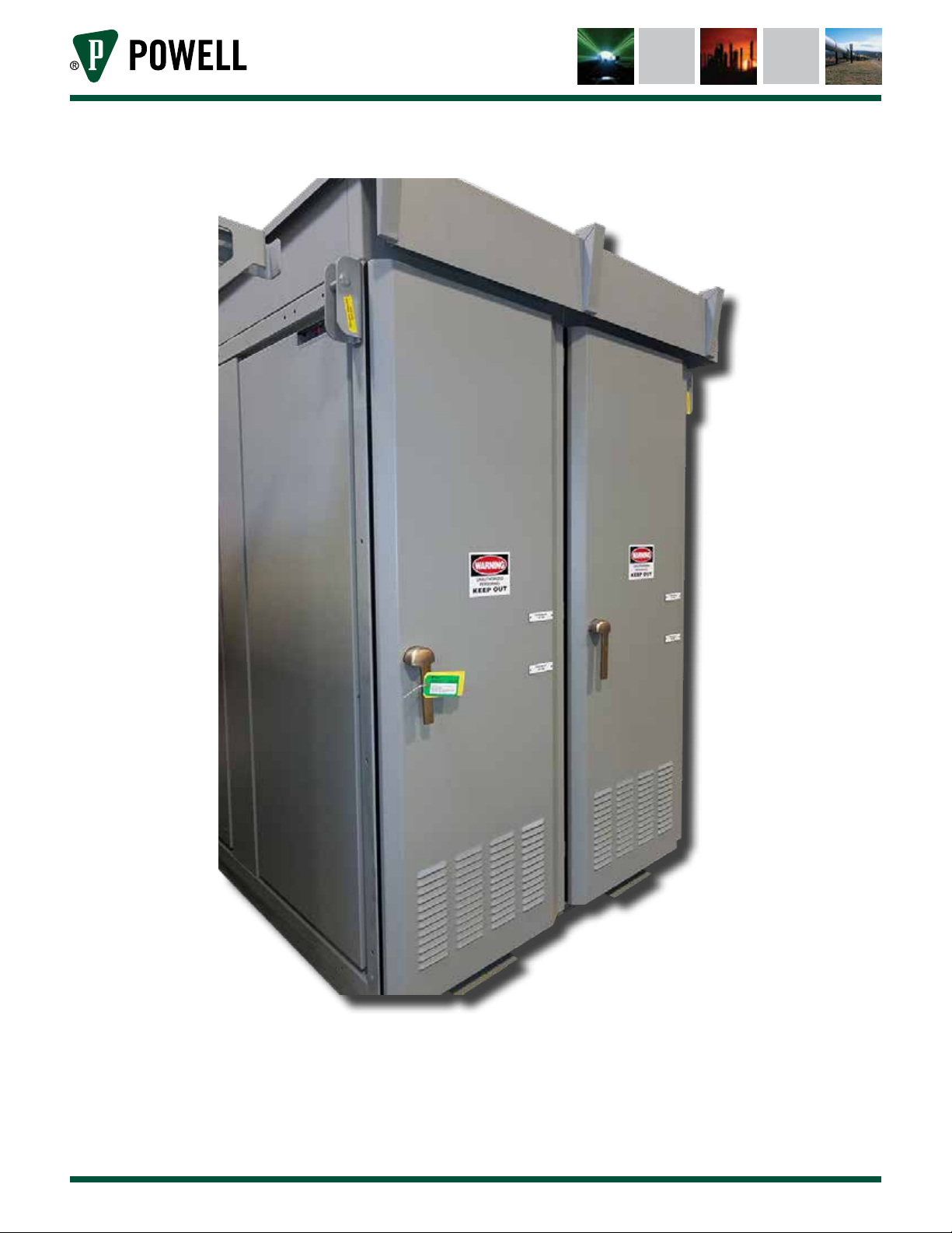
Figure 2 Typical Outdoor Power/Vac® Metal-Clad Switchgear Lineup .......................7
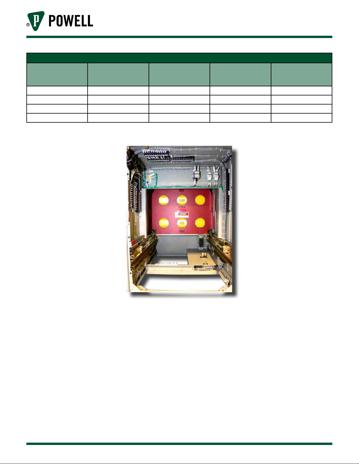
Figure 3 Interior Metal-Clad Switchgear (Lower Compartment) ................................ 8
Figure 4 Primary Disconnecting Device - 1200A .......................................................12
Figure 5 Primary Disconnecting Device - 3000A .......................................................12
Figure 6 Installation Details for Indoor Power/Vac® Metal-Clad Switchgear ...........18
Figure 7 Installation Details for Indoor Power/Vac® Metal-Clad
Switchgear (cont.) ........................................................................................19
Figure 8 Installation Details for Outdoor Power/Vac® Metal-Clad Switchgear ........20
Figure 9 Installation Details for Outdoor Power/Vac® Metal-Clad
Switchgear (cont.) ........................................................................................21
Figure 10 Installation Details for Outdoor Power/Vac® Metal-Clad Switchgear with
Protected Aisle .............................................................................................22
Figure 11 Typical Assembly Details .............................................................................24
Figure 12 Typical Assembly Details (cont.) ..................................................................25
Figure 13 Assembly of Outdoor Switchgear with Protected Aisle ...............................28
Figure 14 Assembly of Outdoor Switchgear with Protected Aisle - (cont.) .................29
Figure 15 Front Upper Compartment ..........................................................................32
Figure 16 View Looking Up Into Front Bottom Compartment of a 2-High .................32
Figure 17 Taptite Location in Front Upper Compartment ........................................... 32
Figure 18 View of Typical Front Lower Breaker Compartment ...................................32
Figure 19 View of Typical Front Lower PT/CPT Rollout Compartment ........................ 33
Figure 20 View of Main Bus Compartment from Front ...............................................33
Figure 21 Location of Tape ........................................................................................... 33
Figure 22 Typical Bus Compartment with Polyester Glass Inter-Unit Bus Support .... 34
Figure 23 View Showing Stacks Bolted Together ........................................................34
Figure 24 Single Bus Bar Arrangement ........................................................................35
Figure 25 Double Bus Bar Arrangement ...................................................................... 35
Figure 26 Typical Rear Tie Bus Compartment with Bus Barrier Removed ..................35
Figure 27 Sectional View of Inter-Unit Bolting ............................................................37
Figure 28 Typical Center Post Bolting ..........................................................................37
Figure 29 Ground Bus Splice Bolt Assembly ................................................................38
Figure 30 Insulation of Bus Bar .................................................................................... 40
Figure 31 Single Bus Bar Connection Joint .................................................................. 41
Figure 32 Double Bus Bar Connection Joint ................................................................41
Figure 33 Tee Connection Joint .................................................................................... 42
Powered by Safety
®
iii

Power/Vac® Metal-Clad Switchgear 5kV & 15kV
01.4IB.67000
Figures
Figure 34 Dead End Bus Joint Insulation .....................................................................42
Figure 35 Installation of Primary Cables ..................................................................... 43
Figure 36 Cable Termination Joint ...............................................................................45
Figure 37 Rear View of Unit Showing Ground Fault Current Transformer .................. 46
Figure 38 Bar-Type Current Transformer Joint Insulation ..........................................46
Figure 39 Roof Bushing ................................................................................................48
Figure 40 Lift Truck .......................................................................................................52
Figure 41 Left Side Racking Rail ..................................................................................56
Figure 42 Right Side Racking Rail ...............................................................................56
Figure 43 Stationary Auxiliary Switch & Circuit Breaker Position Indicator ..............57
iv
Powered by Safety
®

01.4IB.67000
Tables
Table A Standard Dimensions ........................................................................................... 8
Table B Ratings of Medium Voltage Power/Vac Metal-Clad Switchgear .......................... 9
Table C Bolt Torque Values for Power/Vac® Medium Voltage Metal-Clad Switchgear ..39
Table D Bus Wrapping Components ...............................................................................40
Table E Insulation of Bus Bar ........................................................................................... 40
Table F Insulation of Single Bus Bar Connection Joint ................................................... 41
Table G Insulation of Double Bus Bar Connection Joint .................................................41
Table H Insulation of Tee Connection Joint ....................................................................42
Table I Insulation of Dead End Bus Joint .........................................................................42
Table J Cable Termination Joint ......................................................................................45
Table K Bar-Type Current Transformer Joint Insulation ................................................. 46
Table L Pothead, Bushing, or Terminator .......................................................................48
Table M Accessories ......................................................................................................... 64
Powered by Safety
®
v

Power/Vac® Metal-Clad Switchgear 5kV & 15kV
01.4IB.67000
This page is intentionally left blank.
Powered by Safety
®
01.4IB.67000
WARNING
WARNING
NOTICE
NOTICE
Ch 1 General Information
!
The equipment described in this document may contain high voltages and currents which can
cause death or serious injury.
The equipment is designed for use, installation, and maintenance by knowledgeable users of such
equipment having experience and training in the field of high voltage electricity. This document and all
other documentation shall be fully read, understood, and all warnings and cautions shall be abided by. If
there are any discrepancies or questions, the user shall contact Powell immediately at 1.800.480.7273.
!
Prior to adjustments, servicing, maintenance, or any act requiring the operator to make physical
contact with the equipment, the power source must be disconnected and the equipment grounded.
Failure to do so may result in death or serious injury.
The information in this instruction bulletin is not intended to explain all details or variations of the
Powell equipment, nor to provide for every possible contingency or hazard to be met in connection
with installation, testing, operation, and maintenance of the equipment. For additional
information and instructions for particular problems, which are not presented sufficiently for the
user’s purposes, contact Powell at 1.800.480.7273.
Powell reserves the right to discontinue and to change specifications at any time without incurring
any obligation to incorporate new features in products previously sold.
General Information
Powered by Safety
®
1
Power/Vac® Metal-Clad Switchgear 5kV & 15kV
WARNING
NOTICE
01.4IB.67000
A. SCOPE
The information in this instruction bulletin
describes the following Power/Vac® metal-clad
switchgear assemblies:
• 5kV & 15kV
• 20kA, 25kA, 31.5kA, 40kA, 50kA, & 63kA
• 1200A, 2000A, 3000A, 3500A, & 4000A FC
Standard construction details are provided
in the appropriate sections. The circuit
breaker element operation and maintenance
instructions can be found in the circuit breaker
operating instruction manual provided with
each circuit breaker. Any special switchgear
construction details are provided in
supplementary documentation.
B. PURPOSE
The information in this instruction bulletin
is intended to provide details required to
properly operate and maintain the
Power/Vac metal-clad switchgear described in
Ch 1 General Information, A. Scope.
The illustrations contained in this document
may not represent the exact construction
details of each particular type of metal-clad
switchgear. The illustrations in this document
are provided as general information to aid in
showing component locations only.
All illustrations and photos are shown using
deenergized equipment.
!
Follow the appropriate safety precautions
while handling any of the equipment. Failure
to do so may result in death or serious injury.
To the extent required, the products described
herein meet the applicable ANSI, IEEE, and
NEMA Standards; however, no such assurance
is given with respect to local codes and
ordinances which may vary greatly.
C. INSTRUCTION BULLETINS AVAILABLE ELECTRONICALLY
This instruction bulletin provides:
1. Safety guidelines
2. General descriptions of the operation and
maintenance of the Power/Vac metal-clad
switchgear
3. Instructions for installation and placing the
switchgear into service
4. Instructions for part replacement
4. Information for ordering renewal parts
5. Illustrations, photographs, and description
of the switchgear
2
Changes to the instruction bulletin may be
implemented at any time and without notice.
Go to powellind.com to ensure use of the current
instruction bulletin for Powell equipment.
For more information visit powellind.com.
To contact the Powell Service Division call
1.800.480.7273 or 713.944.6900, or email
info@powellservice.com.
For specific questions or comments pertaining
to this instruction bulletin email
documents@powellind.com.
Powered by Safety
®
General Information

01.4IB.67000
Ch 2 Safety
A. SAFE WORK CONDITION
The information in Section A is quoted from
NFPA 70E 2012 - Article 120, 120.1 Establishing an
Electrically Safe Work Condition.
120.1 Process of Achieving an Electrically Safe
Work Condition
1. Determine all possible sources of electrical
supply to the specific equipment. Check
applicable up-to-date drawings, diagrams,
and identification tags.
2. After properly interrupting the load current,
OPEN the disconnecting device(s) for each
source.
3. Wherever possible, visually verify that all
blades of the disconnecting devices are
fully OPEN or that drawout type circuit
breakers are withdrawn to the fully
disconnected position.
4. Apply lockout/tagout devices in accordance
with a documented and established policy.
5. Use an adequately rated voltage detector
to test each phase conductor or circuit part
to verify they are deenergized. Test each
phase conductor or circuit part both
phase-to-phase, and phase-to-ground.
Before and after each test, determine
that the voltage detector is operating
satisfactorily.
Informational Note: See ANSI/ISA-61010-1
(82.02.01)/UL 61010-1, Safety Requirements
for Electrical Equipment for Measurement,
Control, and Laboratory Use - Part 1: General
Requirements, for rating and design
requirements for voltage measurement
and test instruments intended for use on
electrical systems 1000 V and below.
6. Where the possibility of induced voltages
or stored electrical energy exists, ground
the phase conductors or circuit parts
before touching them. Where it could be
reasonably anticipated that the conductors
or circuit parts being deenergized
could contact other exposed energized
conductors or circuit parts, apply ground
connecting devices rated for the available
fault duty.
B. SAFETY GUIDELINES
Study this instruction bulletin and all other
associated documentation before installing the
switchgear.
Each user has the responsibility to instruct
and supervise all personnel associated with
usage, installation, operation, and maintenance
of this equipment on all safety procedures.
Furthermore, each user has the responsibility of
establishing a safety program for each type of
equipment encountered.
The circuit breakers used in the metal-enclosed
switchgear described in this instruction bulletin
are operated by a high-energy,
high-speed mechanism that is interlocked
to provide specific operating sequences. It
is mandatory that the following rules be
observed to ensure the safety of personnel
associated with usage, installation, operation,
and maintenance of these circuit breakers.
The safety rules in this instruction bulletin are
not intended to be a complete safety program.
The rules are intended to cover only some of the
important aspects of personnel safety related to
Power/Vac® metal-clad switchgear.
Safety
Powered by Safety
®
3

Power/Vac® Metal-Clad Switchgear 5kV & 15kV
NOTICE
01.4IB.67000
C. GENERAL
1. Only supervised and qualified personnel
trained in the usage, installation, operation,
and maintenance of the switchgear shall
be allowed to work on this equipment. It
is mandatory that this instruction bulletin,
any supplements, and service advisories be
studied, understood, and followed.
2. Maintenance programs must be consistent
with both customer experience and
manufacturer’s recommendations,
including service advisories and instruction
bulletin(s).
routine maintenance program is essential
for circuit breaker’s reliability and safety.
3. Service conditions and circuit breaker
applications shall also be considered in the
development of safety programs. Variables
include ambient temperature; humidity;
actual continuous current; thermal cycling;
number of operations; interrupting duty;
and any adverse local conditions including
excessive dust, ash, corrosive atmosphere,
vermin and insect infestations.
D. SPECIFIC
1. DO NOT WORK ON ENERGIZED
SWITCHGEAR. If work must be performed
on the switchgear, remove it from service
and place it in an electrically safe condition.
A well planned and executed
serviced only by skilled and knowledgeable
personnel capable of releasing each spring
load in a controlled manner. Detailed
information regarding these mechanisms
is found in the circuit breaker instruction
bulletin.
4. DO NOT ATTEMPT TO CLOSE THE CIRCUIT
BREAKER MANUALLY ON AN ENERGIZED
CIRCUIT.
5. DO NOT USE AN OPEN CIRCUIT BREAKER
AS THE SOLE MEANS OF ISOLATING A
HIGH VOLTAGE CIRCUIT. For complete
isolation, the circuit breaker shall be in
the disconnected position or shall be
withdrawn completely.
6. ALL COMPONENTS SHALL BE
DISCONNECTED BY MEANS OF A VISIBLE
BREAK AND SECURELY GROUNDED FOR
SAFETY OF PERSONNEL PERFORMING
MAINTENANCE OPERATIONS ON THE
SWITCHGEAR.
E. SAFETY LABELS
The equipment described in this document
has DANGER, WARNING, CAUTION, and
instruction labels attached to various locations.
All equipment DANGER, WARNING, CAUTION,
and instruction labels shall be observed when
the circuit breaker is handled, operated, or
maintained.
2. DO NOT WORK ON THE SWITCHGEAR
WITH THE CONTROL CIRCUIT ENERGIZED.
3. EXTREME CARE MUST BE EXERCISED
TO KEEP ALL PERSONNEL, TOOLS, AND
OTHER OBJECTS CLEAR OF MECHANISMS
WHICH ARE TO BE OPERATED,
DISCHARGED, OR RELEASED. These
circuit breakers utilize stored energy
mechanisms. These mechanism must be
4
Warning and Caution labels are located in
various places. Do NOT remove or deface any
of these warning/caution labels.
Powered by Safety
®
Safety

01.4IB.67000
NOTICE
Ch 3 Equipment Description
A. GENERAL
Powell is committed to continuous product
improvement. It is possible that improvements
occurred between revisions to this document
and therefore, may not be described in these
instructions. If the equipment does not
resemble the photographs and descriptions
contained herein, do not attempt to perform
the actions. Contact the Powell Service
Division.
Power/Vac® Metal-Clad Switchgear equipped
with vacuum circuit breakers is designed to
comply with ANSI Standard C37.20.2.
Metal-Clad switchgear is characterized by
removable interrupting devices, isolation
of major circuit elements, grounded metal
compartments, and insulated primary bus
conductors. The metal-clad switchgear is a
line-up of one or more switchgear vertical
sections known as units, which are enclosed
on all sides except for the ventilation openings
and lower unit cable penetrations.
This instruction bulletin should be used in
conjunction with the appropriate instructions
for Vacuum Circuit Breakers, including any
applicable supplement(s), separate instructions
covering other components of the
metal-clad switchgear, and applicable
drawings because each metal-clad switchgear
line-up is custom designed for a particular
use and application. Separate instructions
covering other components are not included in
this publication, but are available upon request.
B. PRIMARY COMPARTMENT
The primary compartment contains the
high voltage equipment and connections. It
consists of the breaker compartments, bus
compartment, cable termination compartment,
and auxiliary compartments for voltage and
control power transformers. Each of these
compartments is separated from the others by
metal barriers for reliability and safety.
Interference interlocks are provided on the
metal-clad switchgear to permit only the circuit
breaker with the correct voltage, continuous
current, MVA and momentary rating to be
inserted.
The metal-clad switchgear is used to protect
and control medium voltage alternating
current power distribution systems. Each
unit consists of a number of circuit breaker
compartments, plus auxiliary compartments
containing accessory apparatus. The circuit
breakers are used to control various types
of circuits, such as incoming lines, bus ties,
feeders, and motor starters. Also, special
functions are provided in great variety and may
be required for particular applications.
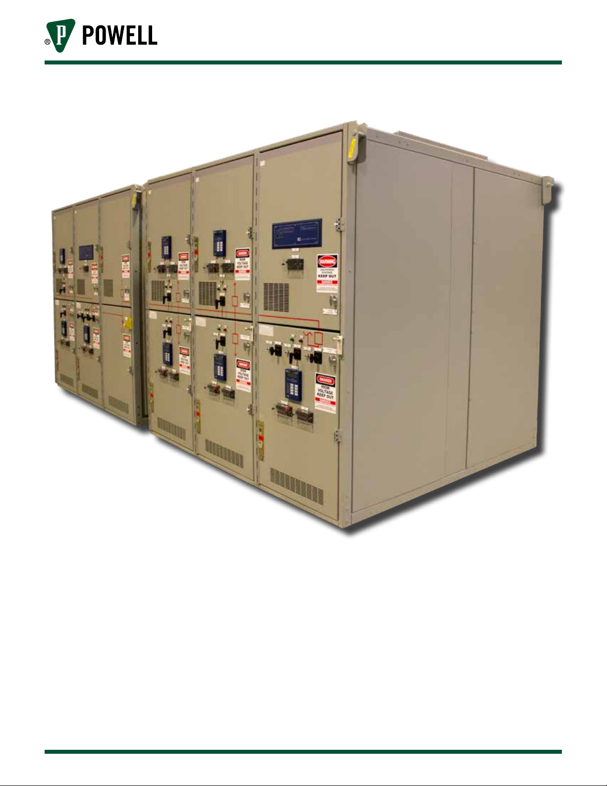
Figure 1 illustrates a typical Power/Vac
metal-clad switchgear line-up.
Equipment Description
Powered by Safety
®
5
Power/Vac® Metal-Clad Switchgear 5kV & 15kV
Figure 1 Typical Indoor Power/Vac® Metal-Clad Switchgear Lineup
01.4IB.67000
6
Powered by Safety
®
Equipment Description
01.4IB.67000
Figure 2 Typical Outdoor Power/Vac® Metal-Clad Switchgear Lineup
Equipment Description
Powered by Safety
®
7
Power/Vac® Metal-Clad Switchgear 5kV & 15kV
Table A Standard Dimensions
01.4IB.67000
Configuration
One-High 1200, 2000, 3000 20, 25, 31.5, 40, 50 & 63 95 94
Two-High 1200, 2000 20, 25, 31.5 40,, 50 & 63 95 94
One- High 3500 20, 25, 31.5 40,, 50 & 63 95 106
One-High 4000 Force Cooled 20, 25, 31.5 40,, 50 & 63 106 106
Continuous Current
Rating (Amperes)
Short-Circuit Rating
(kA)
Figure 3 Interior Metal-Clad Switchgear (Lower Compartment)
Height
(inches)
Depth
(inches)
8
Powered by Safety
®
Equipment Description
01.4IB.67000
Table B Ratings of Medium Voltage Power/Vac Metal-Clad Switchgear
5kV
Maximum
Voltage
Nominal Voltage
4.76 4.16 19 60
7.2kV - 15kV
Maximum
Voltage
Nominal Voltage
15.0 13.8 36 95
Power Frequency
Withstand
(kV)
Power Frequency
Withstand
(kV)
BIL
Crest
(kV)
BIL
Crest
(kV)
Main Bus
Continuous
Current
(A rms)
1200, 2000,
3000, 3500,
4000 FC
Main Bus
Continuous
Current
(A rms)
1200, 2000,
3000, 3500,
4000 FC
Symmetrical
short-circuit
Rating
(kA rms)
Short Time
Current
2 sec.
(kA)
40 40 97
50 50 135
63 63 170
Symmetrical
short-circuit
Rating
(kA rms)
Short Time
Current
2 sec.
(kA)
20 20 52
25 25 67
36 36 97
50 50 135
63 63 170
Momentary
withstand Rating
(kA Crest)
Momentary
withstand Rating
(kA Crest)
C. SECONDARY COMPARTMENT
The secondary compartment is located in the front of the equipment where the circuit breaker
is withdrawn. The compartment is provided with a hinged panel upon which are mounted the
necessary instruments, control and protective devices. The terminal blocks, fuse blocks, and some
control devices are mounted inside the compartment on the side sheets and on the internal device
panel. A wiring space is provided across the top of the switchgear to run wires between vertical
sections.
D. BREAKER REMOVABLE ELEMENT
The Power/Vac® circuit breaker is a vacuum type circuit breaker. It is designed to meet all the
requirements for use in metal-clad switchgear and as such it has all the necessary interlocks and
grounding to interface with the switchgear. It is a removable device, designed with wheels that
make insertion and removal from the compartment a simple operation. All circuit breakers with
equal ratings are interchangeable.
For a detailed description of the circuit breaker and its operation refer to the appropriate instruction
bulletin for Power/Vac vacuum circuit breakers.
Equipment Description
Powered by Safety
®
9

Power/Vac® Metal-Clad Switchgear 5kV & 15kV
01.4IB.67000
E. BREAKER LIFT TRUCK
For ease of breaker handling during installation
and removal, a breaker lift truck is furnished
as a standard accessory with each
Power/Vac switchgear order. This accessory
device is used to elevate the breaker from
the floor or working platform to the level of
the tracks in the switchgear compartment.
Docking of the lifting device rails to the
switchgear tracks is provided for maximum
safety. Refer to Ch 5 Operation, B. Inserting
the Removable Element into the Compartment,
or the latest version of Instruction Bulletin
01.4IB.66000.
F. RATINGS
Ratings of Power/Vac switchgear and circuit
breakers are based on factors supplied in the
following:
G. LIGHTING IMPULSE WITHSTAND (BIL)
The basic impulse level is 60kV for the 4.16kV
class switchgear and 95kV for the 8.25kV and
13.8kV class switchgear. The basic impulse
level testing excludes control transformers,
starting reactors, and autotransformers.
Note: If required, AC Field Dielectric Tests
should be limited to 75% of Factory
Dielectric Test values. Direct current
dielectric testing is not recommended.
If DC testing is required, see
Ch 4 Installation, U. Testing and
Inspection for values to be used.
H. CIRCUIT BREAKER RACKING MECHANISM
The circuit breaker may be placed in three
distinct positions within the circuit breaker
compartment of the switchgear:
• ANSI C37.04 Circuit Breaker Rating
Structure
• ANSI C37.06 Circuit Breaker Ratings
• ANSI C37.20.2 Switchgear Assemblies
See Table B, Ratings of Medium Voltage
Power/Vac® Metal-Clad Switchgear for complete
ratings.
Note: Certain non-standard ratings are
available for special applications.
Consult the manufacturer for details.
Refer to the specific job drawings for
detailed voltage ratings applicable to
particular switchgear line-up.
• Disconnected Position
• Test Position
• Connected Position
In the “disconnected position” the movable
primary disconnects of the circuit breaker are
disengaged and separated at a safe distance
from the stationary primary disconnecting
devices located in the compartment. A metal
shutter covers the openings of the stationary
primary disconnecting devices which prevents
contact. In this position, the secondary
disconnect devices and control contacts are
disengaged.
In the “test position”, the primary disconnecting
devices are disengaged and the shutters are
closed. The secondary circuits are completed
by inserting the secondary disconnect plug
(breaker) into the secondary disconnect
receptacle of the switchgear compartment via
the breaker mounted handle. Now the circuit
breaker may be electrically operated without
affecting the primary circuit.
10
Powered by Safety
®
Equipment Description
01.4IB.67000
CAUTION
Note: At this time the circuit breaker is in
the same physical location as the
“disconnected position”.
In the “connected position”, the movable
primary disconnecting circuits and stationary
primary disconnecting circuits are engaged.
The shutters are open and the secondary
circuits and control contacts are completed.
Interlocks deter the movement of a circuit
breaker from one position to another unless
the circuit breaker is tripped open. The
interlocks also deter closing the breaker
between positions.
For complete instructions on inserting and
withdrawing the circuit breaker in and out
of the switchgear, see Ch 5 Operation of this
bulletin and also refer to the applicable
Power/Vac® circuit breaker instruction bulletin.
!
If the circuit breaker main closing spring
is charged, withdrawing the secondary
disconnect plug will cause this main closing
spring to discharge.
grounded receptacle or extension cord. The
230VAC, 50/60Hz model has a three wire four
foot cord to which the purchaser applies his
standard plug.
The remote racking device is provided with a
two position directional switch, an “On-Off”
circuit breaker and a push button control box
attached with a 30 foot extension cord.
Refer to the specific instruction bulletin for
remote racking instructions.
J. PRIMARY DISCONNECT DEVICES
The 1200A and 2000A primary disconnects
consist of two rows of silver-plated copper
fingers mounted on either side of the circuit
breaker studs. These fingers are held in place
with a spider which positions the fingers and
fastens them to the breaker. Wipe pressure is
obtained by tension springs between the rows
of fingers which pull them together. When the
circuit breaker is connected to the metal-clad
studs, the spring force on the fingers is divided
between the breaker stud and metal-clad studs
(Figure 4).
I. REMOTE RACKING
The optional electrically operated racking
device provides a convenient means for
racking a breaker between the connected and
test positions from a remote location. It is
easily mounted to the breaker compartment
front door and is designed for quick transfer
between units.
The remote racking device is furnished in
two operating voltage versions. The 115VAC,
50/60Hz model has a four foot electrical
cord with standard three prong plug to fit a
Equipment Description
Powered by Safety
®
11
Power/Vac® Metal-Clad Switchgear 5kV & 15kV
CAUTION
01.4IB.67000
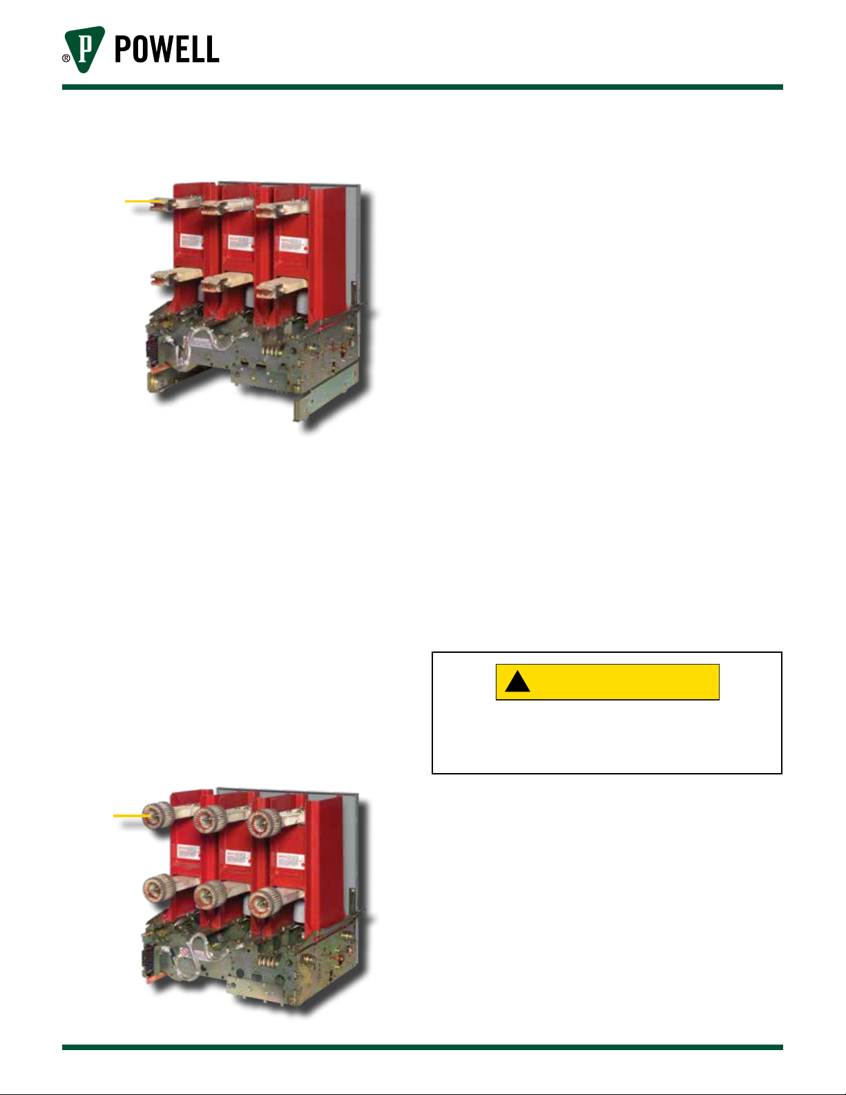
Figure 4 Primary Disconnecting Device -
1200A
a
a. Primary Disconnecting Device
On 3000A primary disconnects, silver-plated
copper fingers are positioned in a circular
configuration and are supported by a
non-magnetic spider. This spider spaces the
fingers equally around the breaker stud and
fastens them to the end of the stud. The
fingers are held in contact with the breaker
stud by a stainless steel garter spring. A second
garter spring on the outer end of the finger
provides contact pressure when the finger
assembly is connected to the tube in the
metal-clad unit (Figure 5).
Figure 5 Primary Disconnecting Device -
3000A
K. BUS COMPARTMENT
The main buses are enclosed in a metal
compartment with removable front covers to
provide accessibility. The bus is supported and
insulated by molded glass-reinforced polyester
barriers which are flame retardant and track
resistant. Polyester supports with porcelain
sleeves may be furnished as an option in 5kV
and 15kV equipment.
Bus bars are insulated with an extruded
thermoplastic insulation sleeving or an
applied epoxy insulation using the fluidized
bed process. All bolted joints have
silver-to-silver connections for low contact
resistance. Most joints are insulated with a
molded polyvinyl chloride boot.
L. CURRENT TRANSFORMER COMPARTMENT
Current transformers are mounted over the
primary bushings in the rear of the breaker
compartment and are isolated from the breaker
by the shutter barrier. They are front accessible
by removal of the shutter barrier.
!
The equipment must be deenergized before
any component is touched or serious injury
could result.
a
a. Primary Disconnecting Device
12
M. PRIMARY TERMINATION SPACE
The primary termination space of each breaker
unit is isolated from the other equipment
by metal barriers. Space is provided in this
compartment for connecting the customer’s
primary cable by means of potheads or clamp
type terminals. Two-hole NEMA drilling for
two cables per phase is provided at all cable
connection points.
Powered by Safety
®
Equipment Description

01.4IB.67000
WARNING
In double breaker vertical sections, a steel duct
serves as a pull-box and barrier to separate the
two outgoing cable circuits.
The primary termination space of a unit is
accessible by removal of the bolted rear cover.
N. VOLTAGE TRANSFORMERS
The voltage transformers are mounted on a
rollout carriage equipped with primary and
secondary disconnecting devices. When the
voltage transformers are disconnected, they
are at a safe striking distance from all live parts
of the metal-clad switchgear. In addition, a
grounding device is provided which contacts
the fuses when the voltage transformers are
disconnected, effectively discharging the
transformers. In this position, the transformer
fuses may be safely removed and replaced.
When the voltage transformer rollout tray is
in the disconnected position, the rear barrier
of the tray effectively deters access to the
stationary primary disconnects mounted in the
compartment behind the rollout tray. However,
these stationary primary disconnects may
remain energized.
O. CURRENT-LIMITING FUSES AND CONTROL POWER
TRANSFORMER
Current limiting fuses with high interrupting
rating are sometimes used in metal-clad
switchgear to protect small transformers
or circuits where circuit breakers cannot be
economically or functionally justified.
compartment behind their associated fuse
carriage and their secondary breaker is located
behind a hinged cover on the upper cable
compartment.
!
Do not remove the rollout tray from its rails
without first deenergizing the primary circuit
to which the roll-out connects. Removing the
tray makes the stationary primary disconnect
devices accessible.
When fuses are disconnected, they are at a
safe striking distance from all live parts of the
switchgear. In addition, a grounding device is
provided which contacts the fuses after they
are disconnected, effectively removing any
static charge from the fuses. In this position,
the fuses may be safely removed and replaced.
The primary disconnecting devices are capable
of interrupting transformer magnetizing
current, but should not be used to interrupt
load current. Mechanical or key interlocks are
applied to prevent operating the disconnecting
device while the load is connected. This is
generally accomplished by interlocking so
that the transformer secondary breaker must
be locked in the open position before the
disconnecting device can be connected or
disconnected.
Current-limiting fuse and control power
transformer rollouts are located in auxiliary
units.
The fuses are mounted on a moveable carriage
equipped with primary and secondary
disconnecting devices. Single phase control
power transformers of 15kV and smaller and
their secondary breaker are mounted on the
carriage with the fuses. Larger control power
transformers, up to 37.5kV single-phase or
75kV three-phase , are located in the cable
Equipment Description
P. DUMMY REMOVABLE ELEMENT (TYPE PVD)
Dummy removable elements are used as a
means of isolating circuits or bus sections
where operation is infrequent and a circuit
breaker cannot be economically justified. The
device consists of a circuit breaker mechanism
frame and primary insulator supports with
six primary studs including disconnecting
Powered by Safety
®
13
 Loading...