

Powell 3-135/400-3W User Manual
Induction Power Supplies
3kW; 135 – 400kHz
(Integral Heat Station)
User’s Guide
Model 3-135/400-3
Model 3-135/400-3W
Rev E 12/1/04

Table of Contents
1. SPECIFICATIONS AND FEATURES....................................................................................3
1.1. Output...........................................................................................................................3
1.2. Input..............................................................................................................................3
1.3. Physical ........................................................................................................................3
1.4. Front panel controls and indicators...............................................................................4
1.5. Internal heat station......................................................................................................4
1.6. Protection......................................................................................................................5
1.7. Load..............................................................................................................................5
1.8. Cooling Water……………………………………………………………………………….…5
2. GETTING STARTED .............................................................................................................6
2.1. Safety Warnings ...........................................................................................................6
2.2. Set-Up ..........................................................................................................................6
3. CONNECTIONS.....................................................................................................................7
3.1. Load..............................................................................................................................7
3.2. 230VAC input voltage...................................................................................................7
3.3. Circuit Breaker..............................................................................................................8
3.4. Terminal Block # 1........................................................................................................8
3.5. Terminal Block # 2........................................................................................................8
4. FRONT PANEL OPERATION ...............................................................................................9
4.1. Limit and trip indicators.................................................................................................9
4.2. Heat ON/OFF indicators. ............................................................................................10
4.3. Program status indicators...........................................................................................10
4.4. Voltage, Current and Frequency Indicators. ...............................................................10
4.5. Reset Button...............................................................................................................10
4.6. Heat switch.................................................................................................................10
4.7. Power Pot...................................................................................................................10
4.8. MODE switch..............................................................................................................11
4.9. E-Stop button..............................................................................................................11
4.10. Program buttons.......................................................................................................11
4.11. Power Display Indicator............................................................................................11
4.12. Start frequency adjustment.......................................................................................11
4.13. Feedback selection...................................................................................................12
5. PROGRAMMING IN AUTO MODE......................................................................................13
5.1. Entering a program.....................................................................................................13
5.2. Running a program.....................................................................................................14
5.3. Enabling external connections....................................................................................14
6. LOAD STATION TUNING....................................................................................................15
6.1. Tuning.........................................................................................................................15
6.2. Changing the heat station components. .....................................................................16
7. APPENDIX A: USER INTERFACE......................................................................................17
7.1. Terminal Block 1.........................................................................................................17
7.2. Terminal Block 2.........................................................................................................17
8. APPENDIX B: TUNING EXAMPLES................................................................................18
2

1. Specifications and features
1.1. Output
Maximum Power 3kW
1
Maximum Apparent Power 6.6kVA @ 230V input
Minimum Power Factor 0.50 @ 230 V input
Duty Cycle 100%
Maximum Voltage 350V rms
2
Frequency 135kHz to 400kHz
Maximum Response Time 0.1s
3
Minimum Allowed OFF-Time 0.5s
1.2. Input
AC line-to-line voltage
AC line current 14.5A @ 230V
AC power 3.6kVA
208V – 240V ± 10%, 50 to 60Hz
1.3. Physical
Dimensions: Length
Width
Height
20.5in (521mm)
11.7in (297mm)
12.7in (323mm)
Weight 43.5lb (20kg)
1
3kW is output power. 3.6kVA input power allows for losses in the power supply.
2
Limited by rating of resonant capacitors.
3
When using the adjustable start-frequency feature.
3

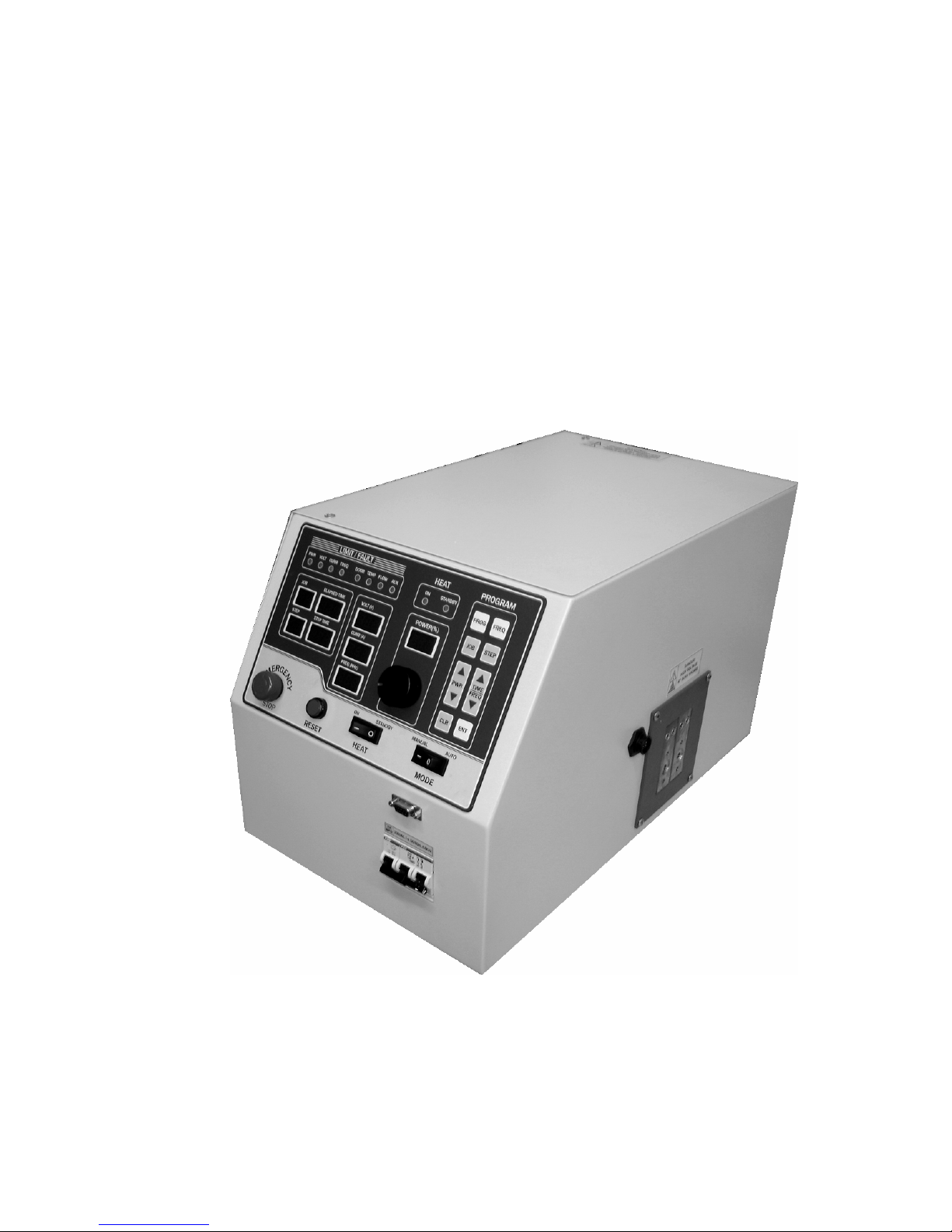
1.4. Front panel controls and indicators
LED Indicators
Yellow indicator for power limit.
Yellow indicator for voltage limit.
Yellow or red indicator (dual color) for
inverter current limit or trip respectively.
Yellow or red indicator (dual color) for
frequency limit or trip respectively.
Individual red indicators for door,
temperature, flow and/or auxiliary
interlock trips.
Numeric Displays Run time read-outs for output voltage,
inverter current and frequency
Power Meter (0-100%)
Job number (Auto mode)
Step (Auto mode)
Step Time (Auto mode)
Elapsed time (Manual and Auto mode)
Controls – Manual Mode Rocker switch for output power
ON/OFF.
Single turn knob for power level.
(Manual mode)
Pushbutton to reset trips.
Rocker switch for manual or auto
(programmed) operation.
Emergency stop button.
Freq button to select start frequency
Controls – Programmed Mode Program, Job, Step, Freq, Pwr,
Time/Freq, Clear and Enter buttons for
programming automatic mode
operation.
1.5. Internal heat station
Resonant capacitors Two 660nF, 350V capacitors supplied.
Series inductor Adjustable for load matching.
4

1.6. Protection
Power Limited to 3kW in any feedback
configuration
Inverter output current Limited to 70A peak. Short circuit
protected.
Resonant capacitor voltage Limited to 350V rms
Line current 20A Circuit breaker
Temperature and cooling Air-cooling provide by three fans.
Heatsink temperature switch for
protection.
Safety Interlocks Emergency stop button or door switch
opens the main circuit breaker.
1.7. Load
Quality factor of load Will operate with any load Q (including
resistive loads), provided that the
output frequency and voltage is within
the specifications.
1.8. Cooling Water
Maximum pressure 100PSI (690kPa)
Minimum differential pressure 30PSI (207kPa)
Minimum water flow .5GPM (0.032l/s)
Maximum inlet water temperature
Minimum water resistivity
Supply hose location Back of Cabinet
105°F (41°C)
590Ω.in (1500Ω.cm)
5
2. Getting started
2.1. Safety Warnings
Have all operation, maintenance and servicing performed by qualified personnel only.
1. Read this operation manual completely before using the power supply.
2.
3. Do not touch live electrical parts. In operation, this means the output connectors,
Induction heating can be dangerous. Obey all warnings on unit and in manual.
the work coil, the work piece, and any bus work or cabling connecting them.
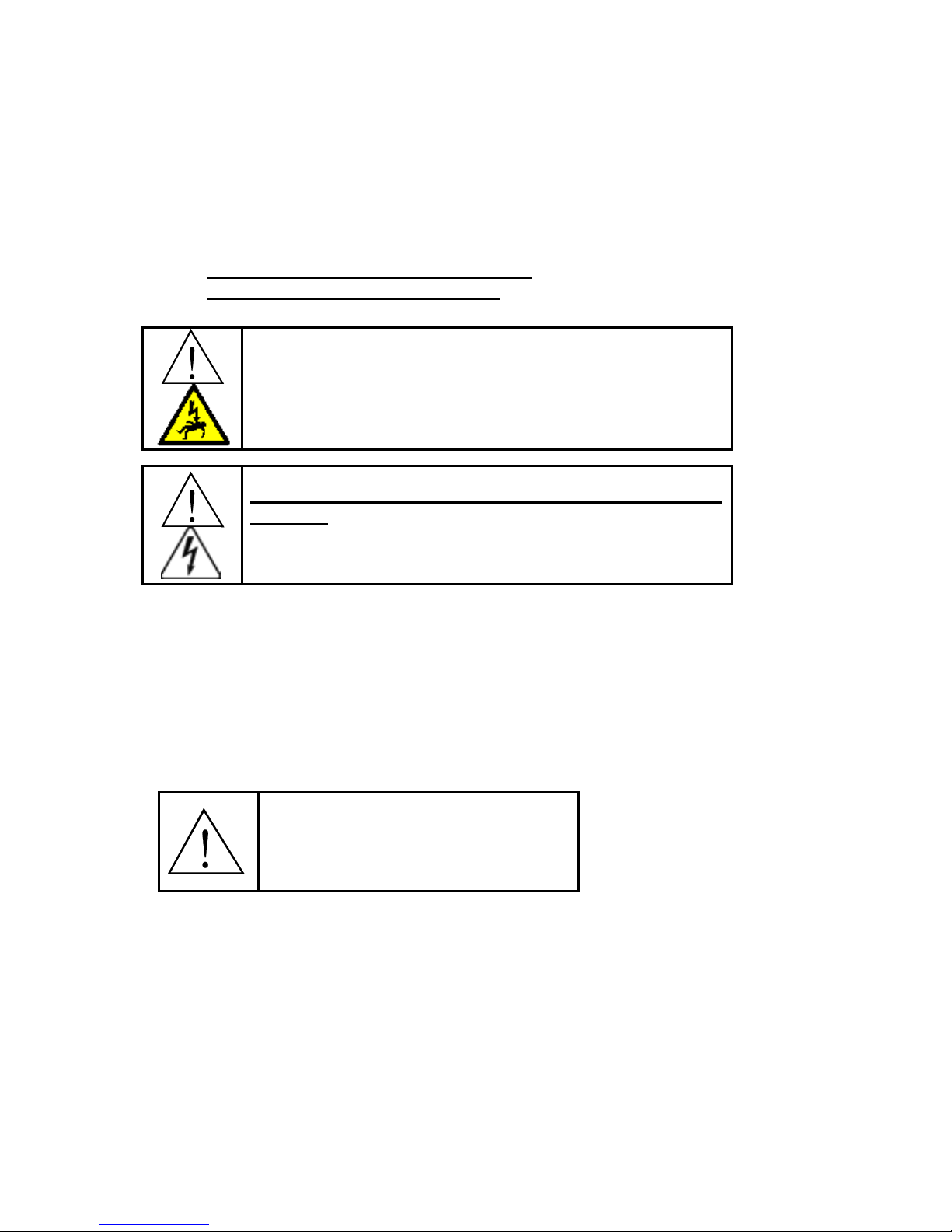
WARNING: These symbols, placed at the outputs of the
power supply, warn of the electric shock hazard there
and RF burn hazard at the outputs when the unit is
operating.
Disconnect input power before installing or servicing
this unit. The door interlock will open the breaker if the
cover is removed. However, the input AC voltage is live
at the top of the main circuit breaker.
2.2. Set-Up
The following is a list of steps describing the required actions to get the power supply set up.
1. Loosen the two quarter turn fasteners and remove the cover from the unit. Check for any
visual damage that could have happened during shipment. Check all plug-in connectors of
PCBs.
2. Connect the heating coil to the output of the unit (see section 3.1. on page 7).
3. Read section 4. on page 9 to become familiar with the front panel controls.
WARNING: Make sure that the
power is locked out before
connecting AC power to the unit.
Connect only 208-240VAC.
4. Ensure that the circuit breaker (identified by → in Figure 1) on the unit is in the OFF
position. Connect the power cord to a 230V single phase power source as described in
section 3.2. on page 7.
5. Perform the tuning of the heat station, as described in section 6.1. on page 15.
6. The unit is now ready for operation, and can either be controlled by the front panel (control
selection switches in “INT” position), or by external (control selection switches in “EXT”
position.
6
 Loading...