

Powell 05PV36ARMX-4, 15PV50ARMX-4, 15PV25ARMX-4, 15PV36ARMX-4, 15PV63ARMX-4 Instruction Bulletin
...
Powered by Safety
®
Instruction Bulletin - 01.4IB.60306
PowlVac® ARG & ARM Series 4
Vacuum Circuit Breakers
5kV & 15kV
1200A, 2000A, & 3000A
25kA, 36kA, 50kA, & 63kA

PowlVac® ARG & ARM Series 4 Vacuum Circuit Breakers
5kV & 15kV - 1200A, 2000A, & 3000A - 25kA, 36kA, 50kA, & 63kA
Contact Information
Powell Electrical Systems, Inc.
powellind.com
info@powellind.com
01.4IB.60306
Service Division
PO Box 12818
Houston, Texas 77217-2818
Tel: 713.944.6900
Fax: 713.948.4569
Powered by Safety
®
01.4IB.60306
DANGER
WARNING
CAUTION
CAUTION
NOTICE
Signal Words
As stated in ANSI Z535.4-2007, the signal word is
a word that calls attention to the safety sign and
designates a degree or level of hazard seriousness.
The signal words for product safety signs are
“Danger”, “Warning”, “Caution” and “Notice”.
These words are defined as:
!
DANGER indicates an imminently hazardous
situation which, if not avoided, will result in
death or serious injury.
!
WARNING indicates a potentially hazardous
situation which, if not avoided, could result in
death or serious injury.
Qualified Person
For the purposes of this manual, a qualified
person, as stated in NFPA 70E®, is one who has
skills and knowledge related to the construction
and operation of the electrical equipment and
installations and has received safety training to
recognize and avoid the hazards involved. In
addition to the above qualifications, one must also
be:
1. trained and authorized to energize,
deenergize, clear, ground, and tag circuits
and equipment in accordance with
established safety practices.
2. trained in the proper care and use of
personal protective equipment (PPE)
such as rubber gloves, hard hat, safety
glasses or face shields, flash clothing, etc.,
in accordance with established safety
practices.
3. trained in rendering first aid if necessary.
!
CAUTION, used with the safety alert symbol,
indicates a hazardous situation which, if not
avoided, could result in minor or moderate
injury.
CAUTION, used without the safety alert
symbol, is used to address practices not
related to personal injury.
NOTICE is used to address practices not related
to personal injury.
Powered by Safety
®

PowlVac® ARG & ARM Series 4 Vacuum Circuit Breakers
5kV & 15kV - 1200A, 2000A, & 3000A - 25kA, 36kA, 50kA, & 63kA
01.4IB.60306
This page is left blank intentionally.
Powered by Safety
®

01.4IB.60306
Contents
Ch 1 General Information .................................................................................................1
A. Scope ................................................................................................................................................................2
B. purpoSe .............................................................................................................................................................2
c. InStructIon BulletInS AvAIlABle electronIcAlly .....................................................................................................3
D. ASSocIAteD BulletInS ..........................................................................................................................................3
Ch 2 Safety ........................................................................................................................ 4
A. SAfe Work conDItIon .........................................................................................................................................4
B. SAfety GuIDelIneS ...............................................................................................................................................5
c. GenerAl .............................................................................................................................................................6
D. SpecIfIc ..............................................................................................................................................................6
e. X-rAyS ..............................................................................................................................................................7
f. SAfety lABelS .....................................................................................................................................................7
Ch 3 Equipment Description ............................................................................................. 8
A. GenerAl .............................................................................................................................................................8
B. the StoreD enerGy MechAnISM ............................................................................................................................8
1) Mechanical Description .......................................................................................................................................................... 8
2) Electrical Description .............................................................................................................................................................19
c. AutoMAtIc rAckInG MechAnISM ......................................................................................................................... 20
1) Breaker Position Indicator ....................................................................................................................................................20
2) Interlocking ..............................................................................................................................................................................20
3) Blocking Interlock ...................................................................................................................................................................21
4) Racking Mechanism ..............................................................................................................................................................21
D. cIrcuIt BreAker coMpArtMent InterfAceS ........................................................................................................... 22
1) Primary Disconnecting Devices .......................................................................................................................................... 22
2) Secondary Disconnecting Devices ..................................................................................................................................... 22
3) MOC (Mechanism Operated Cell Switch) Actuator ........................................................................................................22
4) TOC (Truck Operated Cell Switch) Actuator .....................................................................................................................22
5) Ground Connection ............................................................................................................................................................... 22
6) Shutter Rollers ......................................................................................................................................................................... 23
7) Anti-Rollout Latch ..................................................................................................................................................................23
e. vAcuuM InterrupterS ....................................................................................................................................... 23
f. vAcuuM Interrupter connectIon ....................................................................................................................... 23
1) 25kA, 36kA, & 50kA Rated Circuit Breakers ......................................................................................................................23
2) 63kA Rated Circuit Breakers ................................................................................................................................................. 23
Powered by Safety
®
i

PowlVac® ARG & ARM Series 4 Vacuum Circuit Breakers
5kV & 15kV - 1200A, 2000A, & 3000A - 25kA, 36kA, 50kA, & 63kA
01.4IB.60306
Contents
Ch 4 Installation..............................................................................................................24
A. receIvInG ........................................................................................................................................................ 24
B. hAnDlInG ........................................................................................................................................................ 25
c. StorAGe .......................................................................................................................................................... 25
D. plAcInG the cIrcuIt BreAker Into ServIce ............................................................................................................ 26
1) High Voltage Insulation Integrity ....................................................................................................................................... 26
2) Vacuum Integrity .................................................................................................................................................................... 28
3) Control Voltage Insulation Integrity .................................................................................................................................. 29
4) Mechanical Operation Check .............................................................................................................................................. 29
5) Electrical Operation Check ...................................................................................................................................................30
e. InSertInG the cIrcuIt BreAker Into the cIrcuIt BreAker coMpArtMent .................................................................... 31
1) Prior to Inserting the Circuit Breaker into the Circuit Breaker Compartment ..........................................................32
2) Inserting the Circuit Breaker to the
Test/Disconnected Position ..................................................................................................................................................33
3) Inserting the Circuit Breaker to the Connected Position ...............................................................................................34
4) Emergency Racking In Procedure .......................................................................................................................................34
f. reMovInG the cIrcuIt BreAker froM the cIrcuIt BreAker coMpArtMent ................................................................. 35
1) Removing the Circuit Breaker from the Connected to the Test/Disconnected Position ........................................35
2) Removing the Circuit Breaker from the
Test/Disconnected Position out of the Circuit Breaker Compartment ......................................................................36
3) Emergency Racking Out Procedure ...................................................................................................................................37
Ch 5 Maintenance ........................................................................................................... 38
A. GenerAl DeScrIptIon ........................................................................................................................................ 38
1) Introduction .............................................................................................................................................................................38
2) Inspection and Cleaning ......................................................................................................................................................39
B. MechAnISM AreA ............................................................................................................................................. 39
1) Mechanical Operation .......................................................................................................................................................... 39
2) Lubrication ...............................................................................................................................................................................40
3) Closing Spring Removal ........................................................................................................................................................ 44
4) Slow Closing of Mechanism .................................................................................................................................................45
5) Mechanism Adjustments ......................................................................................................................................................45
6) Electrical Operation ...............................................................................................................................................................50
c. vAcuuM Interrupter AnD contAct AreA ............................................................................................................. 50
1) Vacuum Interrupter and Contact Erosion ........................................................................................................................50
2) Vacuum Integrity .................................................................................................................................................................... 50
3) Mechanical Adjustment of Vacuum Interrupters ...........................................................................................................50
D. optIonAl MAIntenAnce proceDureS ................................................................................................................... 50
1) High Potential Tests ...............................................................................................................................................................50
2) Timing .......................................................................................................................................................................................51
3) Primary Resistance Check ....................................................................................................................................................51
ii
Powered by Safety
®

01.4IB.60306
Contents
Ch 6 Recommended Renewal Parts and Replacement Procedures ...............................52
A. orDerInG InStructIonS ..................................................................................................................................... 52
B. recoMMenDeD reneWAl pArtS ........................................................................................................................... 52
c. replAceMent proceDureS .................................................................................................................................. 52
1) Vacuum Interrupter Assembly ............................................................................................................................................. 53
2) Sliding Contact Finger Assembly (for circuit breaker rated up to 50kA only) ..........................................................53
3) Closing Coil Assembly ...........................................................................................................................................................53
4) Primary Shunt Trip Coil Assembly ......................................................................................................................................53
5) Secondary Shunt Trip Coil Assembly .................................................................................................................................53
6) Undervoltage Device Assembly (UV) ................................................................................................................................. 53
7) Charging Motor Assembly ...................................................................................................................................................53
8) Anti-Pump Relay Assembly ..................................................................................................................................................54
9) Latch Check Switch ................................................................................................................................................................ 54
10) Motor Cutoff Switch Assembly ............................................................................................................................................54
11) Auxiliary Switch ......................................................................................................................................................................54
12) Ground Connection Assembly ............................................................................................................................................54
13) Racking Motor .........................................................................................................................................................................54
Powered by Safety
®
iii

PowlVac® ARG & ARM Series 4 Vacuum Circuit Breakers
5kV & 15kV - 1200A, 2000A, & 3000A - 25kA, 36kA, 50kA, & 63kA
01.4IB.60306
Figures
Figure 1 PowlVac® ARG & ARM Series 4 Circuit Breaker Front View with Cover ..........9
Figure 2 PowlVac® ARG & ARM Series 4 Circuit Breaker Front View without Cover ..10
Figure 3 PowlVac ARG & ARM Series 4 Circuit Breaker Rear View .............................11
Figure 4 Primary Current Closeups ............................................................................12
Figure 5 Cam and Fundamental Linkage Positions ...................................................14
Figure 6 Mechanism and Trip Linkages ...................................................................... 15
Figure 7 Operation Sequence .....................................................................................17
Figure 8 Typical Control Scheme ................................................................................18
Figure 9 Circuit Breaker in Shipping Carton ...............................................................24
Figure 10 Circuit Breaker with Shipping Bracket .........................................................24
Figure 11 Circuit Breaker on Crane ...............................................................................25
Figure 12 Secondary Disconnect Override Device ....................................................... 30
Figure 13 Removing Circuit Breaker from Compartment ............................................ 36
Figure 14 Lubrication (50kA shown) ............................................................................42
Figure 15 Lubrication (50kA shown) (cont.) .................................................................43
Figure 16 Main Closing Spring Assembly Compressed for Removal ...........................44
Figure 17 Main Closing Spring Assembly Installed .....................................................44
Figure 18 Primary Trip Prop Adjustment ......................................................................46
Figure 19 Feeler Gauge .................................................................................................47
Figure 20 Latch Check Switch Adjustment ...................................................................48
Figure 21 Primary Current Path ....................................................................................56
Figure 22 Control Devices ............................................................................................. 58
iv
Powered by Safety
®

01.4IB.60306
Tables
Table A Field Dielectric Test Values ..................................................................................27
Table B Lubrication ..........................................................................................................41
Table C Timing .................................................................................................................. 51
Table D Primary Resistance .............................................................................................51
Table E Primary Current Path ..........................................................................................55
Table F Control Devices ....................................................................................................57
Table G Miscellaneous Parts ............................................................................................ 59
Table H Miscellaneous Parts (cont.) .................................................................................60
Powered by Safety
®
v

PowlVac® ARG & ARM Series 4 Vacuum Circuit Breakers
5kV & 15kV - 1200A, 2000A, & 3000A - 25kA, 36kA, 50kA, & 63kA
01.4IB.60306
This page is left blank intentionally.
Powered by Safety
®
01.4IB.60306
WARNING
WARNING
NOTICE
NOTICE
Ch 1 General Information
!
The equipment described in this document may contain high voltages and currents which can
cause death or serious injury.
The equipment is designed for use, installation, and maintenance by knowledgeable users of such
equipment having experience and training in the field of high voltage electricity. This document and all
other documentation shall be fully read, understood, and all warnings and cautions shall be abided by. If
there are any discrepancies or questions, the user shall contact Powell immediately at 1.800.480.7273.
!
Prior to adjustments, servicing, maintenance, or any act requiring the operator to make physical
contact with the equipment, the power source must be disconnected and the equipment grounded.
Failure to do so may result in death or serious injury.
The information in this instruction bulletin is not intended to explain all details or variations of the
Powell equipment, nor to provide for every possible contingency or hazard to be met in connection
with installation, testing, operation, and maintenance of the equipment. For additional
information and instructions for particular problems, which are not presented sufficiently for the
user’s purposes, contact Powell at 1.800.480.7273.
Powell reserves the right to discontinue and to change specifications at any time without incurring
any obligation to incorporate new features in products previously sold.
General Information
Powered by Safety
®
1
PowlVac® ARG & ARM Series 4 Vacuum Circuit Breakers
WARNING
5kV & 15kV - 1200A, 2000A, & 3000A - 25kA, 36kA, 50kA, & 63kA
01.4IB.60306
A. Scope
The information in this instruction bulletin
describes the following PowlVac® ARG
(Automatic Racking Generator) & ARM
(Automatic Racking Mechanism) Series 4
vacuum circuit breakers:
• 05PV36ARMX-4 1200, 2000, & 3000A
• 05PV36ARMM-4 1200, 2000, & 3000A
• 05PV50ARMX- 1200, 2000, & 3000A
• 05PV50ARMM-4 1200, 2000, & 3000A
• 05PV63ARMX-4 1200, 2000, & 3000A
• 05PV63ARMM-4 1200, 2000, & 3000A
• 15PV25ARMX-4 1200, 2000, & 3000A
• 15PV25ARMM-4 1200, 2000, & 3000A
• 15PV36ARMX-4 1200, 2000, & 3000A
• 15PV36ARMM-4 1200, 2000, & 3000A
• 15PV50ARMX-4 1200, 2000, & 3000A
• 15PV50ARMM-4 1200, 2000, & 3000A
B. purpoSe
The information in this instruction bulletin
is intended to provide details required to
properly install, operate, and maintain the
PowlVac ARG & ARM Series 4 vacuum circuit
breakers described in Ch 1 General Information,
A. Scope.
This instruction bulletin provides:
1. Safety guidelines
2. General descriptions of the operation and
maintenance of the PowlVac ARG & ARM
Series 4 vacuum circuit breakers
3. Instructions for installation and placing the
circuit breaker into service
4. Instructions for part replacement
5. Information for ordering renewal parts
6. Procedure for critical adjustments
7. Illustrations, photographs, and description
of the circuit breakers
• 15PV63ARMX-4 1200, 2000, & 3000A
• 15PV63ARMM-4 1200, 2000, & 3000A
• 15PV63ARGX-4 1200, 2000, & 3000A
• 15PV63ARGM-4 1200, 2000, & 3000A
The illustrations contained in this document
may not represent the exact construction
details of the PowlVac ARG & ARM Series 4
vacuum circuit breakers. The illustrations
in this document are provided as general
information to aid in showing component
locations.
All illustrations and photos are shown using
deenergized equipment.
!
Follow the appropriate safety precautions
while handling any of the equipment. Failure
to do so may result in death or serious injury.
To the extent required, the products described
herein meet the applicable ANSI, IEEE, and
NEMA Standards; however, no such assurance
is given with respect to local codes and
ordinances which may vary greatly.
2
Powered by Safety
®
General Information

01.4IB.60306
NOTICE
c. InStructIon BulletInS AvAIlABle electronIcAlly
Changes to the instruction bulletin may be
implemented at any time and without notice.
Go to powellind.com to ensure use of the current
instruction bulletin for Powell equipment.
For more information visit powellind.com.
To contact the Powell Service Division call
1.800.480.7273 or 713.944.6900, or email
info@powellservice.com.
For specific questions or comments pertaining
to this instruction bulletin email
documents@powellind.com with the IB number
in the subject line.
D. ASSocIAteD BulletInS
• 01.4IB.51000C PowlVac® Metal-Clad
Switchgear 5kV & 15kV
• 01.4IB.51200C PowlVac-AR® Arc Resistant
Switchgear 5kV & 15kV
General Information
Powered by Safety
®
3

PowlVac® ARG & ARM Series 4 Vacuum Circuit Breakers
5kV & 15kV - 1200A, 2000A, & 3000A - 25kA, 36kA, 50kA, & 63kA
01.4IB.60306
Ch 2 Safety
A. SAfe Work conDItIon
The information in Section A is quoted from
NFPA 70E 2018 - Article 120, 120.5 Establishing an
Electrically Safe Work Condition.
120.5 Process or Establishing and Verifying an
Electrically Safe Work Condition. Establishing
and verifying an electrically safe condition shall
include all of the following steps, which shall be
performed in the order presented, if feasible:
1. Determine all possible sources of electrical
supply to the specific equipment. Check
applicable up-to-date drawings, diagrams,
and identification tags.
2. After properly interrupting the load current,
open the disconnecting device(s) for each
source.
N Exception No. 1: An adequately rated
permanently mounted test device shall be
permitted to be used to verify the absence of
voltage of the conductors or circuit parts at
the work location, provided it meets the all
following requirements: (1) It is permanently
mounted and installed in accordance with
the manufacturer’s instructions and tests
the conductors and circuit parts at the point
of work; (2) It is listed and labeled for the
purpose of verifying the absence of voltage;
(3) It tests each phase conductor or circuit
part both phase-to-phase and phase-toground; (4) The test device is verified as
operating satisfactorily on any known voltage
source before and after verifying the absence
of voltage.
N Exception No. 2: On electrical systems over
1000 volts, noncontact test instruments shall
be permitted to be used to test each phase
conductor.
3. Wherever possible, visually verify that all
blades of the disconnecting devices are
fully open or that drawout-type circuit
breakers are withdrawn to the fully
disconnected position.
4. Release stored electrical energy.
5. Release or block stored mechanical energy.
6. Apply lockout/tagout devices in accordance
with a documented and established
procedure.
7. Use an adequately rated portable test
instrument to test each phase conductor or
circuit part to verify it is de-energized. Test
each phase conductor or circuit part both
phase-to-phase and phase-to-ground.
Before and after each test, determine
that the test instrument is operating
satisfactorily through verification on any
known voltage source.
Informational Note No. 1: See UL 61010-1,
Safety Requirements for Electrical Equipment
for Measurement, Control, and Laboratory
Use, Part 1: General Requirements, for
rating, overvoltage category, and design
requirements for voltage measurement
and test instruments intended for use on
electrical system 1000 volts and below.
N Informational Note No. 2: For additional
information on rating and design
requirements for voltage detectors, refer
to IEC 61243-1, Live Working - Voltage
Detectors - Part 1: Capacitive type to be used
for voltages exceeding 1kV a.c., or IEC 61243-
2, Live Working - Voltage Detectors - Part 2:
Resistive type to be used for voltages of 1kV
to 36kV a.c., or IEC 61243-3, Live Working Voltage Detectors - Part 3: Two-pole voltage
type.
4
Powered by Safety
®
Safety

01.4IB.60306
8. Where the possibility of induced voltages
or stored electrical energy exists, ground
the phase conductors or circuit parts
before touching them. Where it could be
reasonably anticipated that the conductors
or circuit parts being de-energized
could contact other exposed energized
conductors or circuit parts, apply temporary
protective grounding equipment in
accordance with the following:
a.. Placement. Temporary protective
grounding equipment shall be placed
at such locations and arranged in such
a manner as to prevent each employee
from being exposed to a shock hazard
(i.e., hazardous differences in electrical
potential). The location, sizing, and
application of temporary protective
grounding equipment shall be
identified as part of the employer’s job
planning.
b. Capacity. Temporary protective
grounding equipment shall be capable
of conducting the maximum fault
current that could flow at the point of
grounding for the time necessary to
clear the fault.
N Informational Note: ATSM F855, Standard
Specification for Temporary Protective
Grounds to be Used on De-energized Electric
Power Lines and Equipment, is an example
of a standard that contains information on
capacity of temporary protective grounding
equipment.
B. SAfety GuIDelIneS
Study this instruction bulletin and all other
associated documentation before uncrating
the circuit breakers.
Each user has the responsibility to instruct and
supervise all personnel associated with usage,
installation, operation, and maintenance of this
equipment on all safety procedures.
Furthermore, each user has the responsibility
of establishing a safety program for each type
of equipment encountered.
The circuit breakers described in this
instruction bulletin are operated by a
high-energy, high-speed mechanism that
is interlocked to provide specific operating
sequences. It is mandatory that the following
rules be observed to ensure the safety of
personnel associated with usage, installation,
operation, and maintenance of this circuit
breaker.
The safety rules in this instruction bulletin are
not intended to be a complete safety program.
The rules are intended to cover only some of the
important aspects of personnel safety related
to PowlVac® ARG & ARM Series 4 vacuum circuit
breakers.
Safety
c. Impedance. Temporary protective
grounding equipment and connections
shall have an impedance low enough
to cause immediate operation
of protective devices in case of
unintentional energizing of the electric
conductors or circuit parts.
Powered by Safety
®
5

PowlVac® ARG & ARM Series 4 Vacuum Circuit Breakers
5kV & 15kV - 1200A, 2000A, & 3000A - 25kA, 36kA, 50kA, & 63kA
01.4IB.60306
c. GenerAl
1. Only supervised and qualified personnel
trained in the usage, installation, operation,
and maintenance of a circuit breaker shall
be allowed to work on this equipment. It is
mandatory that the appropriate instruction
bulletins, supplements, and service
advisories be studied, understood, and
followed.
2. Maintenance programs must be consistent
with both customer experience and
manufacturer’s recommendations,
including service advisories and instruction
bulletin(s).
A well planned and executed
routine maintenance program is essential
for circuit breaker’s reliability and safety.
3. Service conditions and circuit breaker
applications shall also be considered in the
development of safety programs. Variables
include ambient temperature; humidity;
actual continuous current; thermal cycling;
number of operations; interrupting duty;
and any adverse local conditions including
excessive dust, ash, corrosive atmosphere,
vermin and insect infestations.
D. SpecIfIc
1. DO NOT WORK ON AN ENERGIZED
CIRCUIT BREAKER. If work must be
performed on a circuit breaker, remove it
from service and remove it from the
metal-clad switchgear.
2. DO NOT WORK ON A CIRCUIT BREAKER
WITH THE CONTROL CIRCUIT ENERGIZED.
3. EXTREME CARE MUST BE EXERCISED
TO KEEP ALL PERSONNEL, TOOLS, AND
OTHER OBJECTS CLEAR OF MECHANISMS
WHICH ARE TO BE OPERATED,
DISCHARGED, OR RELEASED.
These circuit breakers utilize stored energy
mechanisms. These mechanisms must be
serviced only by skilled and knowledgeable
personnel capable of releasing each spring
load in a controlled manner. Detailed
information regarding these mechanisms is
found in this instruction bulletin.
4. DO NOT ATTEMPT TO CLOSE THE CIRCUIT
BREAKER MANUALLY ON AN ENERGIZED
CIRCUIT.
5. DO NOT USE AN OPEN CIRCUIT BREAKER
AS THE SOLE MEANS OF ISOLATING A
HIGH VOLTAGE CIRCUIT. For complete
isolation, the circuit breaker shall be in
the disconnected position or shall be
withdrawn completely.
6. ALL COMPONENTS SHALL BE
DISCONNECTED BY MEANS OF A VISIBLE
BREAK AND SECURELY GROUNDED FOR
SAFETY OF PERSONNEL PERFORMING
MAINTENANCE OPERATIONS ON THE
CIRCUIT BREAKERS.
6
Powered by Safety
®
Safety

01.4IB.60306
NOTICE
7. Interlocks are provided to ensure the
proper operating sequences of the circuit
breakers and for the safety of the user. If for
any reason an interlock does not function
as described, do not make any adjustments,
modification, or deform the parts. DO
NOT FORCE THE PARTS INTO POSITION.
CONTACT POWELL FOR INSTRUCTIONS.
e. X-rAyS
When high voltage is applied across the
contacts of a vacuum interrupter, there is the
possibility of generation of X-rays. The intensity
of the X-radiation is dependent on the peak
voltage and the contact gap. At the normal
operating voltage for this type of equipment,
the radiation levels are negligible. At the
voltages specified for testing, test personnel
shall be in front of the circuit breaker such that
the two layers of steel used in the frame and
front cover construction are between the test
personnel and the vacuum interrupters, and
that the test personnel be no closer than one
meter (3’) from the front of the circuit breaker.
THE CIRCUIT BREAKER SHALL BE EITHER
FULLY OPEN, OR FULLY CLOSED WHEN
MAKING HIGH POTENTIAL TESTS. DO NOT
TEST WITH CONTACTS PARTIALLY OPEN.
f. SAfety lABelS
The equipment described in this document
has DANGER, WARNING, CAUTION, and
instruction labels attached to various locations.
All equipment DANGER, WARNING, CAUTION,
and instruction labels shall be observed when
the circuit breaker is handled, operated, or
maintained.
Warning and Caution labels are located in
various places. Do not remove or deface any
of these warning/caution labels.
Safety
Powered by Safety
®
7
PowlVac® ARG & ARM Series 4 Vacuum Circuit Breakers
NOTICE
CAUTION
5kV & 15kV - 1200A, 2000A, & 3000A - 25kA, 36kA, 50kA, & 63kA
01.4IB.60306
Ch 3 Equipment Description
A. GenerAl
Powell is committed to continuous product
improvement.
It is possible that improvements occurred
between revisions to this document and
therefore, may not be described in these
instructions. If the equipment does not
resemble the photographs and descriptions
contained herein, contact Powell before
attempting to perform any actions.
PowlVac® circuit breakers use sealed vacuum
interrupters (Figure 3, f) to control the primary
circuit. The primary connections to the
associated metal-clad switchgear are made
by parallel copper busbars terminating
in multiple contact fingers of the primary
disconnecting devices (Figure 3, c & g). The
primary disconnecting devices, busbars, and
vacuum interrupter assemblies are supported
by insulators (Figure 3, b) specifically designed
for the application.
The primary current path side of the circuit
breaker is considered the rear of the circuit
breaker, while the side with the cover
containing the various indicators and manual
operators is considered the front of the
circuit breaker. By removing the front cover,
the operating mechanisms of the circuit
breaker are exposed. The stored energy
mechanism assembly provides motion to each
of the vacuum interrupters, moving contact
assemblies through operating pushrods
(Figure 4, h & p). In the same metal enclosed
compartment as the stored energy mechanism
is the circuit breaker racking mechanism and
interlocks which control the movement of the
circuit breaker between the test/disconnected
and connected positions. The racking
mechanism provides the motion to
engage/disengage the primary disconnecting
devices and to open/close the shutters in
metal-clad switchgear.
B. the StoreD enerGy MechAnISM
1) Mechanical Description
The stored energy mechanism is located in
the front of the circuit breaker behind the
front cover. The front cover is held in place
by ten (10) cover bolts (Figure 1, a) that
may be removed, allowing access to the
stored energy mechanism and its interlocks,
auxiliary switches, racking mechanism, and
other control devices.
!
Prior to removing the front cover, ensure the
circuit breaker is in the OPEN position and
the main closing spring is fully discharged.
Failure to do so may result in injury.
On the escutcheon of the stored energy
mechanism, there are two (2) indicators
that show the various states of operation
of the mechanism and two (2) manual
operators that will open/close the stored
energy mechanism. The circuit breaker
nameplate (Figure 1, h) is also located on
the mechanism escutcheon. If for any
reason the escutcheon is removed from the
circuit breaker, it shall be verified that the
serial number contained on the nameplate
matches the engraved serial number plate
(Figure 3, q) permanently affixed to the
rear of the circuit breaker frame prior to
installing the escutcheon.
8
Powered by Safety
®
Equipment Description
01.4IB.60306
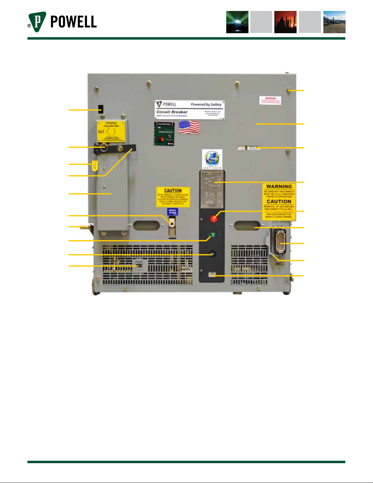
Figure 1 PowlVac® ARG & ARM Series 4 Circuit Breaker Front View with Cover
b
f
g
i
a
c
de
h
k
l
n
p
r
a. Cover Bolts
b. Circuit Breaker Monitor IR Window
c. Front Cover
d. Breaker Position Indicator
e. Emergency Racking Drive Shaft Shutter
f. Padlock Seal
g. Padlock Provision - Movable Arm
h. Nameplate
I. Interlock Window Assembly
j. Manual Trip Operator
j
m
o
q
s
k. Manual Charging Crank
l. MOC Actuator
m. Handle
n. Circuit Breaker Open/Closed Indicator
o. Secondary Disconnect Receptacle
p. Manual Close Operator
q. Secondary Disconnect Latch
r. Operation Counter
s. Spring Charge Indicator
Equipment Description
Powered by Safety
®
9
PowlVac® ARG & ARM Series 4 Vacuum Circuit Breakers
5kV & 15kV - 1200A, 2000A, & 3000A - 25kA, 36kA, 50kA, & 63kA
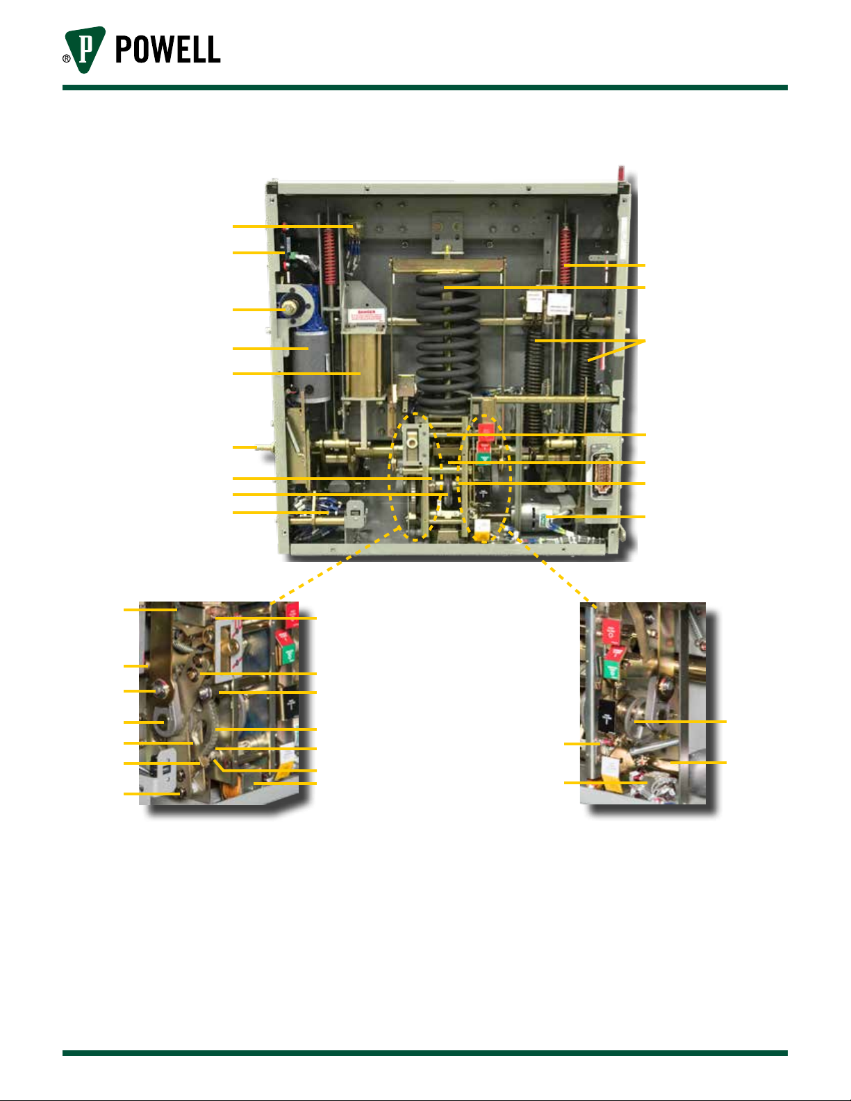
Figure 2 PowlVac® ARG & ARM Series 4 Circuit Breaker Front View without Cover
a
01.4IB.60306
b
e
g
h
j
l
n
o
q
r
c
d
f
i
k
m
p
s
u
w
y
ab
ad
a. Anti-Pump Relay
b. Circuit Breaker Monitor™
(Optional)
c. Opening Spring
d. Main Closing Spring
e. Emergency Racking Drive Shaft
f. Anti-Bellows Springs (63kA only)
g. Racking Motor
h. Shock Absorber (Dashpot)
i. Secondary Trip Prop
j. MOC Actuator
k. Main Cam Roller
10
t
v
x
z
aa
ac
l. Reset Spring
m. Camshaft
n. Main Closing Cam
o. Auxiliary Switch
p. Charging Motor
q. Latch Check Switch
r. Secondary Trip Prop Adjusting Screw
s. Jackshaft
t. Holding Pawl Support Arm
u. Crank Pin
v. Holding Pawl Adjusting Eccentric
Powered by Safety
®
ae
af
ag
ah
w. Crank Arm
x. Ratchet Wheel
y. Pawl Lift Drive Plate
z. Close Latch Arm
aa. Close Latch Shaft
ab. Drive Pawl
ac. Closing Coil
ad. Pawl Support Arm
ae. Motor Cutoff Cam
af. Close Bar Adjusting Screw
ag. Charging Motor Drive Shaft
ah. Motor Cutoff Switch
Equipment Description
01.4IB.60306
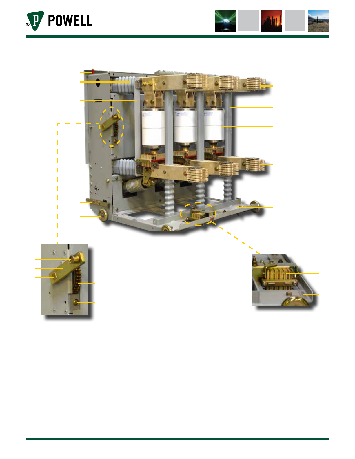
Figure 3 PowlVac ARG & ARM Series 4 Circuit Breaker Rear View
a
b
d
c
e
f
g
m
h
j
k
l
n
o
a. TOC Actuator
b. Main Insulator (Wishbone)
c. Upper Primary Disconnecting Device
d. Support Strut
e. Insulating Pole Support
f. Vacuum Interrupter
g. Lower Primary Disconnecting Device
h. Anti-Rollout Latch
J. Wheel
k. Crank Arm Roller
l. Racking Crank Arm
m. Racking Shaft
n. Worm Gear
o. Racking Drive Shaft
p. Ground Connection
q. Serial Number Plate
i
p
q
i. Frame
Equipment Description
Powered by Safety
®
11
PowlVac® ARG & ARM Series 4 Vacuum Circuit Breakers
5kV & 15kV - 1200A, 2000A, & 3000A - 25kA, 36kA, 50kA, & 63kA
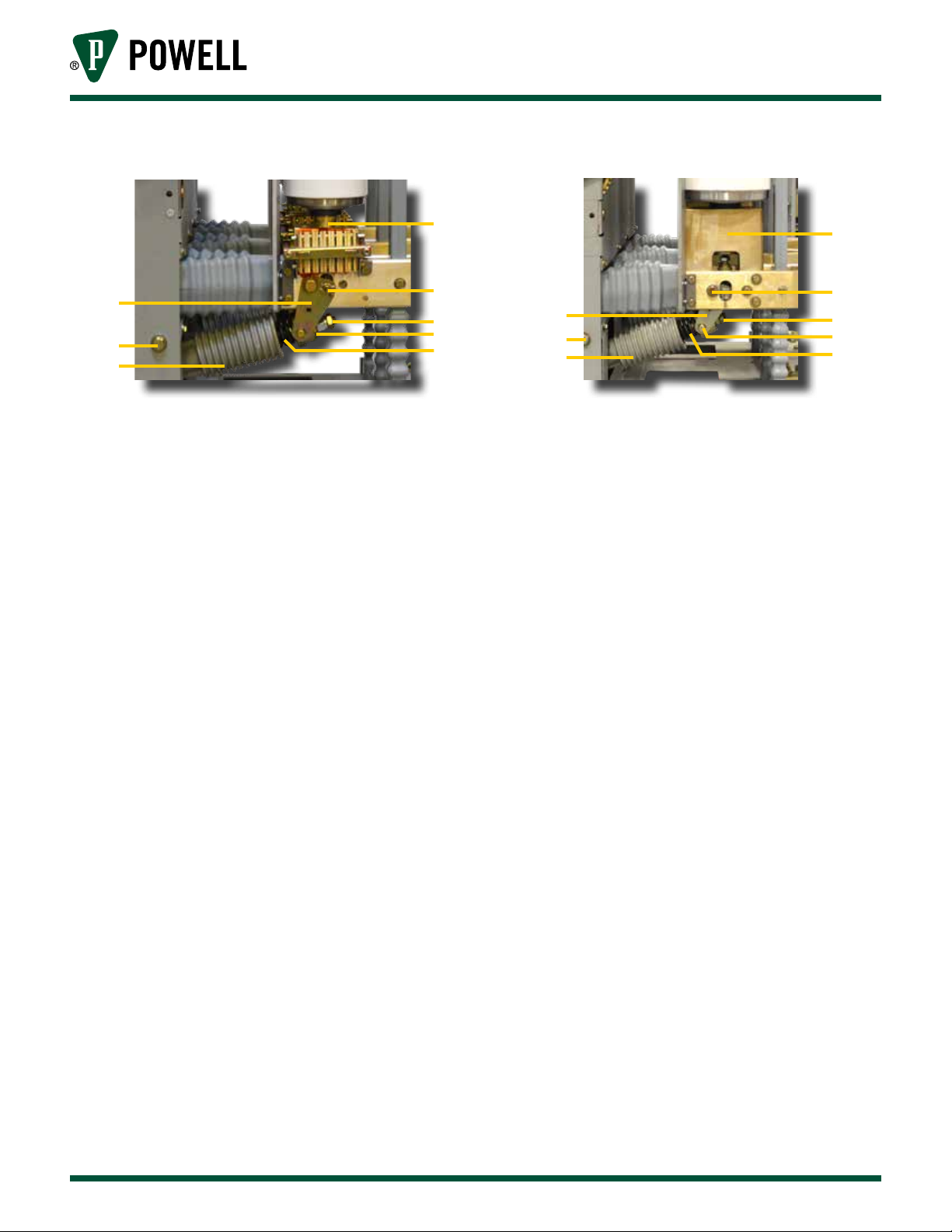
Figure 4 Primary Current Closeups
01.4IB.60306
c
f
h
Up to 50kA
a. Lower Vacuum Interrupter Casting
b. Operating Pin
c. Bell Crank
d. Lock Nut
e. Spring Yoke
f. Jackshaft Pin
g. Contact Loading Spring
h. Operating Pushrod
a
b
d
e
g
k
o
p
i
j
l
m
n
63kA Only
i. Lower Vacuum Interrupter Casting
j. Operating Pin
k. Bell Crank
l. Lock Nut
m. Spring Yoke
n. Contact Loading Spring
o. Jackshaft Pin
p. Operating Pushrod
12
Powered by Safety
®
Equipment Description
 Loading...