

Page 1

IM
■ay
(Whhy^ ' -y
WkMji , .
xcr _ K
Always Wear Eye Protection. During Operation.
1
I 'C.
, WARNING:
'•i’'? lead the Operator’s
' ai'.d toliow all Warnings
' i / t if.'■ructions. Failure to
f i,!i in serious iiyury.
Page 2

CAUTiOM: ALWAYS DISCONMECTIPIR^ FLUt , A L A^'A' »‘l'‘LE'*Y!FIEWHf:RElTCAN-
‘TWIilTACT SPARK PLUG TO PrEVtNTAC&‘C-WALL rABAL‘ ^ «HER SETTINGUP,
TRANSPOeilNG, ADJUSTING OR MAKING
IMPORTA..^'T
:.An : ^ "3 liFULiRE OPERATOR PRESENCE CO ' ^nS'»«' iWiU: v. OY : “-^S|-ljRV YOUR
UN'? '-OUP-4 ‘ 1» YTKSUC HCONTROtS, DO NOT ATTEMPT TO CE« n>L f U. ‘.‘ION OF >’Ht OPERATOR
RKS .V K. r UNDER ANY CiRC'JMSTANCES.
I riMiNii'iu;
• Know the controls and how to stop quickly. Read this owner’s
manual and instructions furnished with attachments.
• Do not allow children to operate the machine. Do not allow
adults to operate it without proper instruction,
• Do not carry passengers. Do not mow when children and oth
ers are around.
• Do not attempt to operate your vehicle or mower when not in
the driver’s seat.
• Always get on or off your vehicle from the operator’s left hand
side.
• The vehicle and attachments should be stopped and inspected
for damage after striking a foreign object, and the damage
should be repaired before restarting and operating the equip
ment.
PREPARATION:
. 'V': V' v.f I i i,r I 1 If, r,,i //.'a, ^.j
'■'•ih f|., ill ' ''. ,.d <,it:
'-Y .t' it 'loi'-i i t r.t'j i ( * wra-h "-iicrYe
picked up and thrown.
• Disengage a
the engine.
• Handle oaso
aujirr .
iment clut(
with care - it i
,ifig p
jntaif
jnn
ig or hot
> cool for s
""e dangerous. Do not run the enc
I 'f f V. f, H r It*'-'
3qiipped, or the dellecior shield
jreyes no mind on your vehicle, mowe?
. let other ioterests distract you.
r to attachmc3ots arid stop the ^
i-tc-rs .position.
h( Yw "■p'ra to 'tart
)hr- f m -■jV
Î Tuei lanH
^ r ’ if' i ^ /
es after running
3flled aa
3ine.
,6
il-iinc
-'JCO T..
' - ^ A r n
;:Yf,
,ge - exhaust
i indoors.
' m 1 C‘
Dlac6.
■n
/ bSîOre
id disccn-nct
Uf . ii O'/tn V- ' I -ppe V • ; f ¿*T' litr-^’Ctioriis ■jusure.or
at a speed which couid cause a skid.
Stay alert for holes in the terrain and other hidden hazards.
Keep away from drop-offs.
Do not drive too close to creeks, ditches, and public highways.
Exercise special care when mowing around fixed objects in or
der to prevent the blades from striking them. Never deliberately
run vehicle or mower into or over any foreign objects.
Never shift geans until vehicle comes to a stop.
Never place hands or feet under the mower, in discharge
chute, or near any moving parts while vehicle or mower is run
ning. Alvrays keep clear of discharge chute.
Use care when pulling loads or using heavy equipment.
- Use only approved drawbar hitch points.
- Limit loads to those you can safely control.
- Do not turn sharply. Use care when backing,
- Use counterweight or wheel weights when suggested in
owner’s manual.
Watch out for traffic when crossing or near roadways.
When using any attachments, never direct discharge of mate
rial toward bystanders nor allow anyone near the vehicle while
in operation.
Except for adjustments, do not operate engine if air cleaner or
cover directly over carburetor air intake is removed. Removal of
such part could create a fire hazard.
Do not change the engine governor settings or overspeed the
^hen usir
dam
Mow only in dayiiqht or in good ai
- Shut the enc
Check the blade mounting bolts fc
gueot inisrvc
® Diserigags powi
i“0y0f30 untess c
fy| observation c
® lC0fto ffiP vehicle
arid keep safety devices in piacB and
line off when unclogc
ir to mower before be
iDsoiutBiv necessary
)i tiie entire area behinci the mower.
land attachments inc
or injury may result,
with mower, proceed as follows:
tificial light.
ling chute.
^pr 1 riqhtoessatfre-
’ u Do no« mow in
n on.v alter care-
i , I tiling r nclition,
working.
STORAGE
lipment
Mow
;tOp or
3inc
lit suoden
^hirig hot muf
fling or nc^ in
vehicle uriaO
uiÆ.-i -
If or downhilL
tHsn 15^1
to prevent
:auiion when ensure compliarice with the original
® Never store the eciuipment v^ith gasc isitie a
buiidino where ft
the enoine to cO'
^ To reduce fire ricizarci, keep the engini ives, or
excessive greas
3 ift V:.:-
• Do not operate’j
Î6ITU DsniEged r
hszEf^, Inspect ipenodicallv .and ropis
® Under normal us
to deterioratton iand wear, it should b 1 - d ntly for
bag replace mcîn
menclations or a
■■
ifnes may reach an o|
of Defore storing iri aiiy enCiOsure.
e. Do not Clean proc is run-
vftliout a mii'fflsrs or
nuffiers or spark arre e a fire
>ao6 the Grass C3tc-h€
t. Reoiacement bag ;ked to
Decifications,
' (. Allow
ist sys-
ice if necessary.
subject
recom-
]
Page 3

)NGRATULATfONS on your purchase of a new tractor. It
s been designed, engineered and manufactured to give you
; best possible dependability and performance.
lould you experience any problem you cannot easily rem-
y, please contact your nearest Authorized Service Facility,
ey have competent, well-trained technicians and the proper
)ls to repair this unit.
Base read and retain this manual. The instructions will en-
le you to assemble, operate, and maintain your unit prop-
y. Always observe the “SAFETY RULES”.
MODEL
NUMBER
SERIAL
NUMBER
DATE OFPUROHASE
THE MODEL AND SERIAL NUMBERS WILL BE
FOUND ON A PLATE UNDER THE SEAT.
YOU SHOULD RECORD BOTH SERIAL NUMBER
AND DATE OF PURCHASE AND KEEP IN A SAFE
PLACE FOR FUTURE REFERENCE.
XC1182B
__________________________
USTOMER RESPONSIBILITIES
Read and observe the safety rules.
Follow a regular schedule in maintaining, caring for and us
ing your unit.
Follow the instructions under “Maintenance” and "Storage"
sections of this owner’s manual.
PRODUCT SPECIFICATIONS
HORSEPOWER;
GASOLINE CAPACITY:
OIL:
4.0 PINTS (w/filter change)
3.5 PINTS (w/o filter change)
SPARK PLUG (GAP.025 IN.):
GROUND SPEED:
TIRE PRESSURE:
CHARGING SYSTEM;
BLADE BOLT TORQUE:
WARNING: This unit is equipped with an internal combustion
engine and should not be used on or near any unimproved for
est-covered, brush-covered or grass-covered land unless
the engine’s exhaust system is equipped with a spark arrester
meeting applicable local or state laws (if any) . If a spark arres
ter is used, it should be maintained in effective working order
by the operator.
18.0
3.5 GALLONS
UNLEADED REGULAR
SAE 30 (or 10W-30)
WINTER: SAE 5W-30
CHAMPION RV15YC
1st
2nd
3rd
.071 MPH
1.05 MPH
1.22 MPH
4th 3.24 MPH
5th 4.12 MPH
6th
Rev.
FRONT: 14 PSI
REAR: 10 PSI
15 AMPS @3600 RPM
30-35 FT. LBS.
5.29 MPH
1.62 MPH
Page 4

^iCATIONS ................. 3
ONSiBiLiTIES ............... 3
.......................... 5
....................... 7-10
...................... 10-14
INDEX
Adjustments;
Brake ......................................
Carburetor ................ 24
Mower:
Front-To-Back ......... 20
Side-To-Side .......... 19
Throttle Control Cable ....... 24
Air Filter, Engine ............... 18
Air Screen, Engine ............. 18
Assembly ................ 7—10
B
Battery;
Charging .....................................
Cleaning ................. 17
!n.staliaîion
Levels ..................................
Preparation ................ 8
Starting with Weak Battery ... 23
Storage .................. 25
Terminais ................ 17
Belt:
Motion Drive:
Removal/Replacement.... 22
Mower Blade Drive:
Removal/Replacement.... 21
Mower Drive:
Removal/Replacement.... 21
Blade;
Replacement .............. 16
Sharpening ............... 16
Brake Adjustment .............. 21
Cai'buretor, Adjustment.......... 24
Controls, Tractor ............... 11
Cutting Hidghî, Mower .......... 12
t/ngine;
............ 10
introl Cable
21
8
8,17
.. 24
, . 24
. . 18
. . 18
. . 18
. . 17
, . 18
13,17
. . 17
. , 13
TABLE OF
Starting
Storage ................... 25
Filter:
Air Cleaner ................ 18
Fuel ...................... 18
Oi! ....................... 18
Fuel:
Storage ................... 25
Type ..................... 14
Fuse
.............................. 23
............................... 14
pi-iliiEUM'C Б . ............ 1'-P'
SERVICE AKt kDJUo! te P . ï ............ ^
TFCVF rpr & . . ................ 2b~17
WIRING l 0Hf»AAIIC ... ................. 30
SLOPE SHEET ........................... 31
. i “î ^
H
Headlights .................... 23
Leveling Mower Deck ........ 19—20
Lubrication, Chart ...............................
m
Maintenance ............... 15—18
Air Filter .
Air Screen, Engine .......... 18
Battery .
Blade .................... 16
Cooling Fins, Engine....................18
Engine Oil................................... . 17
Fuel Filter ..
Lubrication Chart . .
Schedule 15
Spark Plugs ............... 18
Tire Care ................ 8,16
Mower:
Adjustment;
Blade Replacement ......... 16
Blade Sharpening
Cutting Height ...........................
Installation ..........
Operation ................. 13
Removal .................. 19
Mowing Tips ................... 14
Muffler 18
Spark Arrester 3
Filter
...
.................................
Foam Pre-Cleaner.................18
...
.................................. 17
...
........................... IS
....
................
Froni-To-Back .......... 20
Side-To-Side ........... 19
................ 16
..............
a
. . . 17
. . , 18
. . . . ... ................. ;e
Operating Mower ............... 13
Operation ....................................11—14
Parking Brake ............... 11,12
15
18
15
12
9
13,17
Parts Bag
Product Specifications
Safety Rules ...............
Schematic ................
Seat ...............................
Service and Adjustments .....
Slope Guide Sheet ..........
Spark Plugs ...............
Specifications ..............
Starting the Engine ..........
Steering Wheel .............
Stopping the Tractor............. 12
Storage ...................
Throttle Control Cable, Adjustment . 24
Tires ....................... 8,16
Troubleshooting ............ 26—27
Wiring Schematic ............... 30
..............................................
............................
s
Carburetor ............
Fuse ................. . ... 23
Mower Adjustment:
Front-To-Back ..... . ... 20
Side-To-Side ......
Motion Drive Belt:
Removal/Replacement . ... 22
Mower Blade Drive Belt:
Removal/Replacement . ... 21
Mower Drive Belt:
Removal/Replacement . ... 21
Mower Removal ........
Throttle Control Cable . . .
Tire Care ............. , . 8,16
w
6
3
. .... 2
. ... 30
..
. .... 8
19—24
, ... 24
.... 19
.... 19
. ... 24
. ... 31
.... 18
........
3
.... 14
. . 7,22
. ... 25
Page 5

LIMITED WARRANTY
The Manufacturer warrants to the original consumer purchaser that this product as manufactured is free from
defects in materials and workmanship. For a period of two (2) years from date of purchase by the originai con
sumer purchaser, we will repair or replace, at our option, without charge for parts or labor incurred in replacing
parts, any part which we find to be defective due to materials or workmanship. This Warranty is subject to the
following limitations and exclusions.
1. This warranty does not apply to the engine, transaxle/transmission components, battery (except as noted
below) or components parts thereof. Please refer to the applicable manufacturer’s warranty on these items.
2. Transportation charges for the movement of any power equipment unit or attachment are the responsibil
ity of the purchaser. Transportation charges for any parts submitted for replacement under this warranty
must be paid by the purchaser unless such return is requested by PouIanAVeed Eater.
3. Battery Warranty: On products equipped with a Battery, we will replace, without charge to you, any bat
tery which we find to be defective in manufacture, during the first year of ownership. After one year, we will
exchange the Battery, chargingyou 1/12 of the price of a newBattery for each full month after one (1) year from
the date of the original sale. Battery must be maintained in, accordance with the instructions furnished.
4. The Warranty period for any products used for rental or commercial purposes is limited to 90 days from the
date of original purchase.
5. This Warranty applies only to products which have been properly assembled, adjusted, operated, and
maintained in accordance with the instructions furnished. This Warranty does not apply to any product which
has been subjected to alteration, misuse, abuse, improper assembly or installation, delivery damage, or to nor
mal wear of the product.
6. Exclusions: Excluded from this Warranty are belts, blades, blade adapters, normal wear, normal adjust
ments, standard hardware and normal in.aintenance.
7. In the event you have a claim under this Warran,ty, you must return the product to an authorized service
dealer.
Should you have any unanswered questions concerning this Warranty, please contact:
Poulan/Weed Eater
549 Canada Avenue
Huron Park, Ontario
Canada NOMIYO
Phone: (519)228-6514
giving the model number, serial number and date of purchase of your product and the name and address of the
authorized dealer from whom it was purchased.
THIS WARRANTY DOES NOT APPLY TO INCIDENTAL OR CONSEQUENTIAL DAMAGES AND ANY IM
PLIED WARRANTIES ARE LIMITED TO THE SAIdE TIME PERIODS STATED HEREIN FOR OUR EX
PRESSED WARRANTIES. Some areas do not allow the limitation of consequential damages or limitations of
how long an implied Warranty may last, so the above limitations or exclusion,s may not apply to you. This War
ranty gives you specific legal rig'hts, and you may have other rights which vary from locale to locale.
This is a limited Warranty within the meaning of that term as defined in the Magnuson-Moss Act of 1975.
Page 6
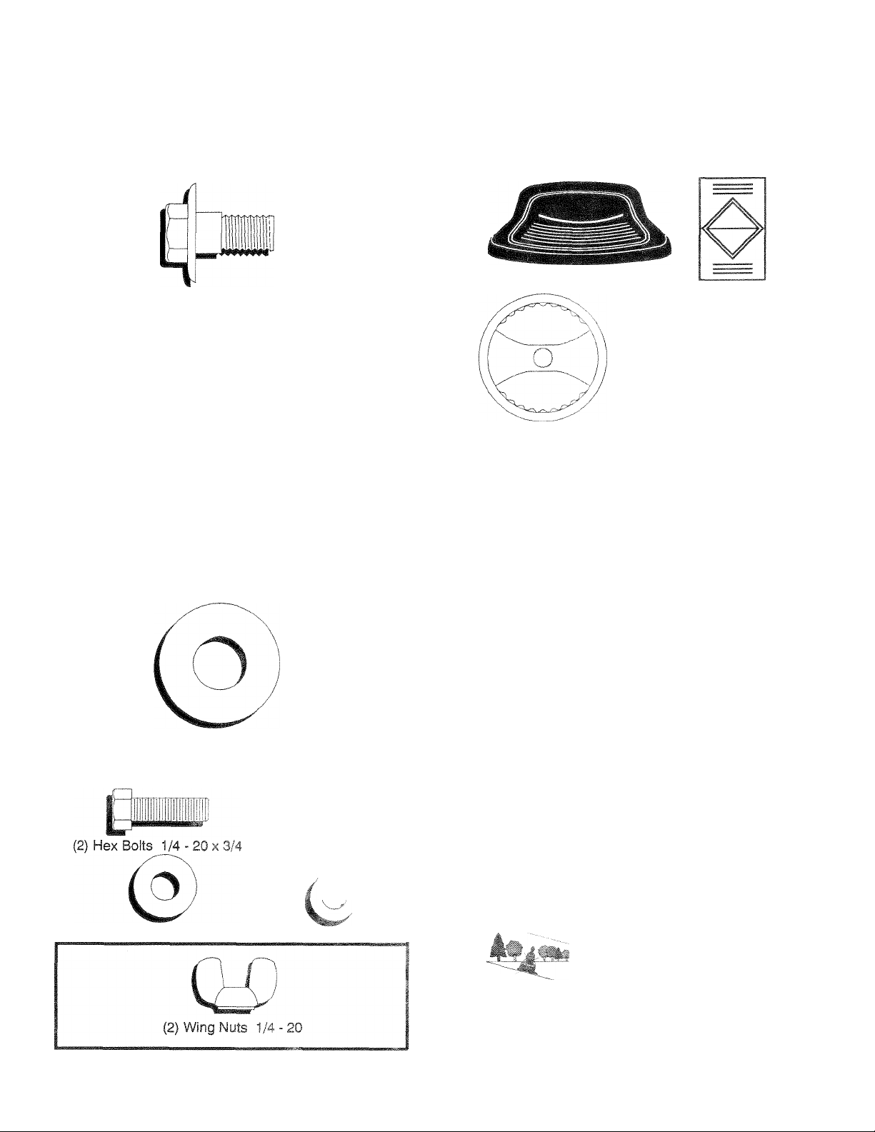
CONTENTS OF HARDWARE PACK
Parts Bag contents shown full size
(1) Shoulder Bolt 5/16-18
=JII
(1) Knob
Parts packed separately in carton
Seat
Steering Wheel
iC I a.
I
___
: ■!
Battery acid
Battery
(1) Washer 17/32 x 1-3/16 x 12 Ga.
ntíi Ì • - 20
(2) Washers 9/32 x5/8x16Ga. (2) Lockwashers 1/4
Owner's Manual
Parts bag contents not shown full size
p Steering
¡I Wheel
(2) Keys
e.'v C-arPage Sc
Terminai Gaarc
Jj insert
QMEBHEúB
, , ' ¿0 . F-1/2
.f!
eírfteryf iS
i< d insti j ‘Oíi6
Page 7
ASSEMBLY
TOOLS REQUIRED FOR ASSEMBLY
A socket wrench set will make assembly easier. Standard
wrench sizes are listed.
(2) 7/16” wrenches
(1) Adjustable Wrench
When right or left hand is mentioned in this manual, it means
when you are in the operating position (seated behind the
steering wheel).
TO REMOVE UNIT FROM CARTON
UNPACK CARTON
Remove all loose parts from carton (See page 6).
Cut, from top to bottom, all four corners of carton and lay
panels flat.
Remove mower deck from skid.
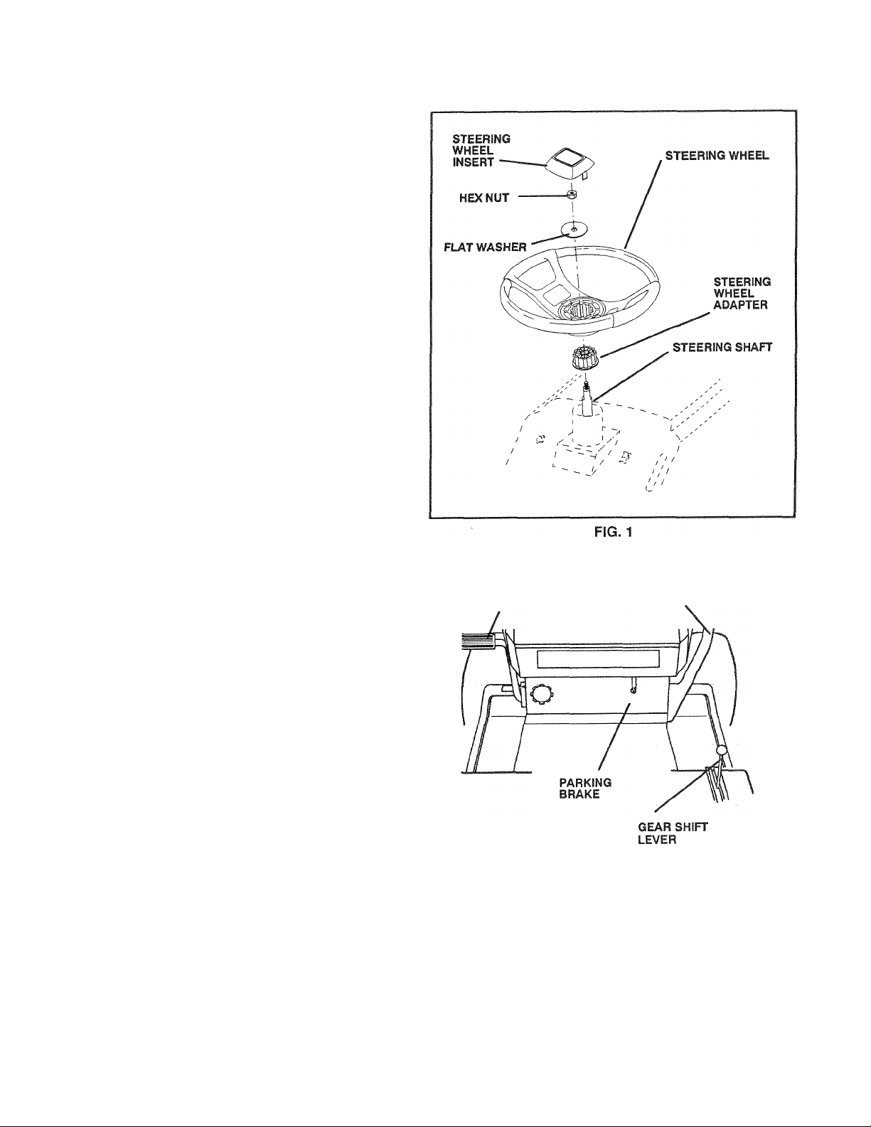
ATTACH STEERING WHEEL (See FIG. 1)
Remove hex nut and large flat washer from steering shaft.
Position front wheels of the tractor so they are pointing
straight forward.
Position steering wheel so cross bars are horizontal (left
to right) and slide onto adapter.
Secure steering wheel to steering shaft with hex nut and
large flat washer previously removed. Tighten securely.
Snap insert into center of steering wheel.
Remove protective plastic from tractor hood.
BEFORE ROLLING UNIT OFF SKID
(See FIG. 2)
IMPORTANT: CHECK FOR AND REMOVE ANY STA
PLES IN SKID THAT MAY PUNCTURE
TIRES WHERE UNIT IS TO ROLL OFF
SKID.
• Raise attachment lift lever to its highest position.
• Release parking brake by depressing clutch/brake pedal.
• Place gearshift lever in “NEUTRAL” position.
• Roll unit backwards off skid.
(1) Tire Pressure Gauge
(1) Utility Knife
CLUTCH/BRAKE
LIFT LEVER
FIG. 2
Page 8
ASSEMBl-V
HOW TO SET UP YOUR TRACTOR
PREPARE BATTERY (See F!G. 3)
CAUTION: Wear eye and face shield.
Wash hands or clothing immecliately if accidentaiSy in contact with battery acid.
not into -upies irt,m charged battery
-'‘i*. 1 fe
R t' the Hvnij .fiurib included with the
c ‘ vent c'''- № th- bag of parts. A!-
'rn/. c ' ‘fec ciotHng and goggles to
y^ul hnndc snd eyes.
Your unit has a battery charging system which is sufficient
for normal use. However, periodic charging of the battery
with an automotive charger will extend its life.
• See instructions packed with vent caps in parts bag.
• Fill battery with acid. Fill each cell until it reaches the bot
tom of the vent wells. Do not over fill.
• Allow battery to stand and settle for at least thirty minutes.
After standing, check the level of acid. If below the vent
wells, add more acid until the correct level is reached.
While battery is standing (after adding acid) and later, while
battery is being charged, continue with assembly of unit.
“ To maximize the life of your battery, it is necessary that
the battery be charged before use. Use a 12 volt battery
charger. Charge battery at a rate of 6 amperes for 1 hour.
Observe all safety precautions required for battery charg
ing. Failure to charge battery can result in a shortened
battery life.
• Check the acid level after the battery is charged. If the acid
has fallen beiow the correct level, add distilled or iron free
water.
• Install the vent caps to cover the vent wells. Wash the top
of the battery with water to remove any acid, then wipe
drv.
dye lie
OiSDO'-
posal I
plastic
while c
jilow insta
QMimm,
y case fo!
jrred in h
xcess ba
frig it to f
iner. Stir
)amifig.
5 on hov
e ‘ -m v'esui- trat'< > n.,rr>-
acid. Neutralize acid for disiches of water in a five gaiion
a 0 > •
intil the addition of more soda
to instsll bHttsrv.
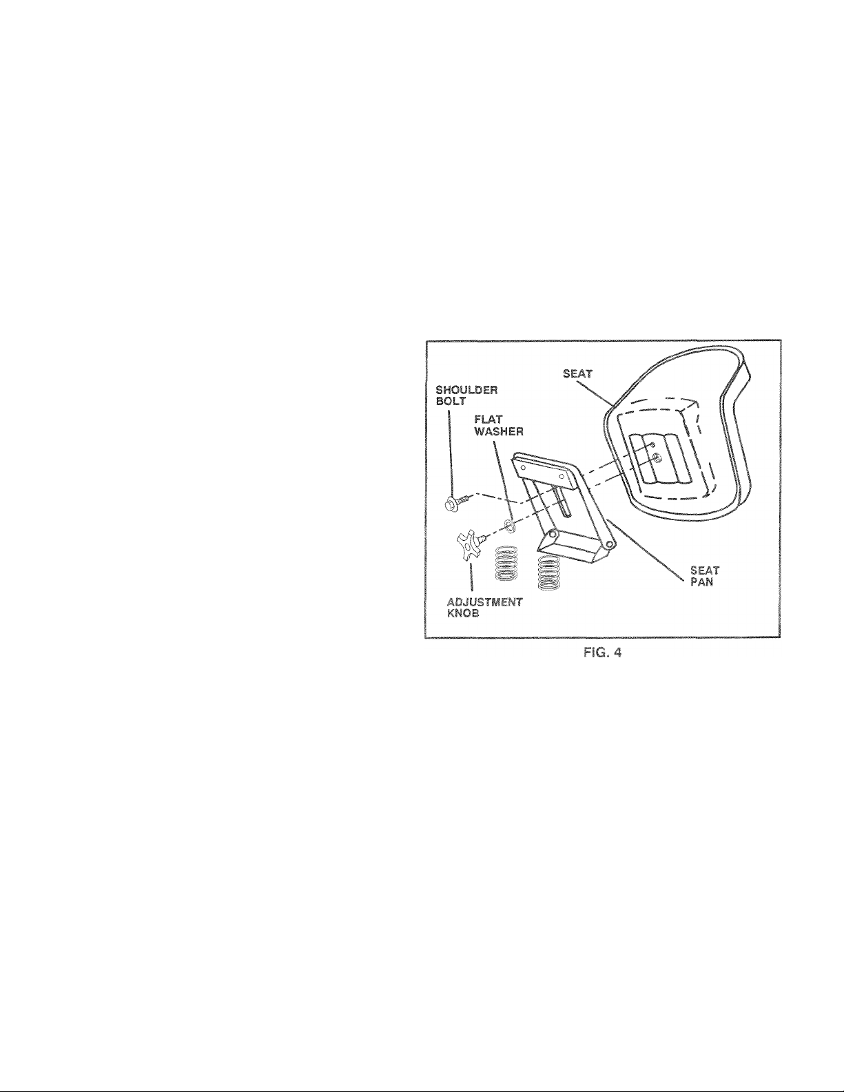
INSTALL SEAT (See FIG. 4)
Adjust seat before tightening adjustment knob.
• Remove cardboard packing on seat pan.
• Place seat on pan and assemble shoulder bolt.
• Assemble adjustment knob and flat washer loosely. Do
not tighten.
• Tighten shoulder bolt securely.
• Lower seat into operating position and sit on seat.
• Slide seat until a comfortable position is reached which al
lows you to press clutch/brake pedal all the way down.
» Get off seat without moving its adjusted position.
• Raise seat and tighten adjustment knob securely.
CHE3A TIRE A* Ac TAUPE
^he L'eiz on -wu' >r.
■hicp.uc f'jrp.ses
er' cut pp—-rr-i'
• Aeduce jre '".'surv lO PS show:, in ‘ PRODUCTSPECiFi'.-ATIC v.F :page 3 o. tuis narueJ,
wevr -.vrint „"ed at the factory for
vreci ~irc prasc.re is important for
CHECK BRAKE SYSTEM
After you learn how to operate your tractor, check to see that
the brake is properly adjusted. See “TO ADJUST BRAKE” in
the Service and Adju.stments section of this manual.
&
I
ill
0.1 'seY
TUBE
H
f
ELL
FIG. 3
Page 9
ASSEMBLY
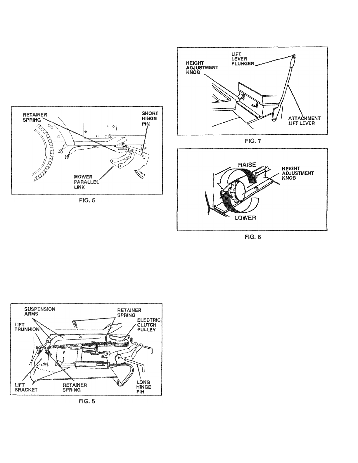
INSTALL MOWER (See
FIGS. 5, 6, 7 & 8)
Your unit has been shipped with the mower parallel link in
cluded in the parts carton. Install mower parallel link on unit
using short hinge pin and retainer spring.
NOTE: Smaller end of parallel link mounts to tractor. Use the
shortest hinge pin for mounting.
Raise attachment lift lever to its highest position.
Remove banding from suspension arms.
Slide mower under tractor with discharge guard to right
side of tractor.
Attach front of mower to parallel link with long hinge pin.
Secure hinge pin with retainer spring.
Turn height adjustment knob to its lowest setting.
Lower attachment lift lever to lower suspension arms. Re
move retainer springs from lift trunnions.
Slide trunnions through upper lift bracket holes and se
cure with retainer springs.
Pull L.H. idler pulley toward the right hand side of tractor
and roll belt over electric dutch pulley.
CHECK DECK LEVELNESS
For best cutting results, mower housing should be properly
leveled. See “TO LEVEL MOWER HOUSING” in the Serv
ice and Adjustments section of this manual.
CHECK FOR PROPER POSITION OF ALL
BELTS
See the figures that are shown for replacing motion, mower
drive, and mower blade drive belts in the Service and Adjust
ments section of this manual. Verify that the belts are routed
correctly.
CHECK BRAKE SYSTEM
After you learn how to operate your tractor, check to see that
the brake is properly adjusted. See “TO ADJUST BRAKE” in
the Service and Adjustments section of this manual.
NOTE: Mower drive belt installation decal located on mower
housing.
• Raise attachment lift lever to raise mower.
• Turn height adjustment knob clockwise to the middle of its
travel.
Page 10
ASSEMBLY
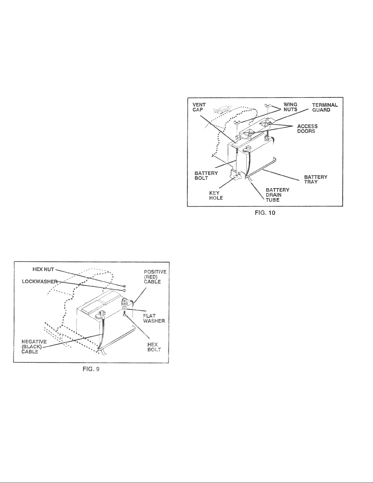
ÍNSTALL battery (See FIGS. 9 & 10)
CAUTION: Do not short battery terminals.
Before installing battery, remove metal
bracelets, wristwatch bands, rings, etc.
Positive terminal must be connected first
A
Raise hood.
Make sure drain tube is fastened to drain hoie in battery
tray and battery tray is positioned in hole of battery sup
port.
Place battery in plastic tray, battery terminals to front of
tractor.
First connect RED battery cable to positive (+) battery ter
minal with hex bolt, flat washer, lockwasher and hex nut
as shown. Tighten securely.
Connect BLACK grounding cable to negative (-) battery
terminal with remaining hex bolt, flat washer, lockwasher
and hex nut. Tighten securely.
Slide the two battery bolts through terminal guard and
start wing nuts onto threads.
Position terminal guard over battery as shown, lower bolts
into key holes and slide square shafts of bolts into slots of
key holes.
Tighten wing nuts by hand making sure battery bolts re
main in slots of key holes in battery support.
Be sure terminal access doors are closed.
to prevent sparking from accidental
grounding.
Use terminal access doors for:
» inspection for secure connections (to tighten hardware)
• Inspection for corrosion
• Testing battery
» Jumping (if required)
• Periodic charging
.^CHECKLIST
BEFORE YOU OPERATE AND ENJOY YOUR NEW
TRACTOR, WE WISH TO ASSURE THAT YOU RECEIVE
THE BEST PERFORMANCE AND SA TISFACTION FROM
THIS QUALITY PRODUCT.
PLEASE REVIEW THE FOLLOWING CHECKLIST:
/ All assembly instructions have been completed.
/ No remaining loose parts in carton.
/ Battery is properly prepared and charged. (Minimum 1
hour at 6 amps).
/ Seat is adjusted comfortably and tightened securely.
/ Ail tires are properly ¡rifiated. (For shipping purposes, the
tires were overinflated at the factory.)
/ Be sure mower deck is properly leveled side-to-side/
front-to-rear for best cutting results. (Tires must be prop
erly inflated for leveling.)
/ Check mower and drive belts. Be sure they are routed
properly around pulleys and inside ail belt keepers.
/ Chsckwiring. See that all connections are still secure and
wires are properly clamped.
WHILE LEARNING HOW TO USE YOUR TRACTOR, PAY
EXTRA ATTENTION TO THE FOLLOWING IMPORTANT
ITEMS:
/ Eng ne oiia' uroo" le
■|;e ankist'itt.n. itt uesh, clean, regular unleaded gaso-
orr. ‘ Tai to
r r inem ’
.;Ü r© t)! 3F, '5' svst©n
'to' f'troir-'ineir (0. . -.dfunc-
0Í 5 ywu ,'h- :the fry • /
iS 'll
aC’b •.
, -rati’to C0<1. H.
Page 11

OPERATION
KNOW YOUR TRACTOR
READ THIS OWNER’S MANUAL AND SAFETY RULES BEFORE OPERATING YOUR TRACTOR.
Compare the illustrations with your Tractor to familiarize yourself with the locations of various controls and adjustments. Save
this manual for future reference.
FIG. 11
ATTACHMENT CLUTCH SWITCH - Used to engage
mower blades or other attachments mounted to your tractor.
LIFT LEVER - Used to raise and lower mower deck or other
attachments mounted to your tractor.
CLUTCH/BRAKE PEDAL - Used for declutching and brak
ing the tractor,
HEIGHT ADJUSTWENT KNOB - Used to adjust the mower
height.
GEARSHIFT LEVER - Selects the speed and direction of
the tractor.
-^r№ÿi;;=
A CAUTION
TO AVOID INJURY
READ OWNER'S MANUAL.
KNOW LOCATION AND FUNCTION OF ALL CONTROLS.
KEEP GUARDS, SAFETY SHIELDS AND SWITCHES IN PLACE AND WORKING.
REMOVE OBJECTS THAT CAN BE THROWN BY BLADES.
DO NOT MOW WHEN CHILDREN AND OTHERS ARE AROUND.
NEVER CARRY CHILDREN OR PASSENGERS.
ALWAYS LOOK BEHIND MACHINE BEFORE BACKING.
DO NOT MOW WHERE MACHINE CAN TIP OR SLIP.
IF MACHINE STOPS GOING UPHILL. STOP BLADE AND BACK DOWN SLOWLY.
BE SURE BLADES AND ENGINE HAVE STOPPED BEFORE PLACING HANDS
OR FEET NEAR THE BLADES.
REMOVE KEY WHEN LEAVING MACHINE.
THROTTLE CONTROL - Used to control engine speed.
IGNITION SWITCH - Used to start and stop the engine.
AMMETER - Indicates battery charging {+) or discharging
(-).
LIGHT SWITCH - Turns the headlights on and off.
PARKING BRAKE LEVER - Locks clutch/brake pedal into
the brake position,
CHOKE CONTROL - Used when starting a cold engine.
Page 12

-îSSzssæsæ^KseBïSi!
The operation of any tractor can result in foreign objects thrown into the eyes, which can resuit
In severe eye damage. Always wear safety glasses or eye shields while operatino your tractor or
before performing any adjustments or repairs. We recommord wide vision safety mask for over
the spectacles or standard safety glasses.
L TA .TOB
: r t WT iiJG BRAKE (See F!G. 12)
• Depress ciutch/brake pedal into full “BRAKE” position and
hold.
f 1. (. ! ‘,i.ik--^i-w3,-,n“ERCiA'3E-D”poF!tionaidre\, i'-; r ■ 1' jm ciutd./b.e ^ep-dil. aa!si-otidre-
.1 • . (I i i./i , |■■•slt¡гп M tke . uff-Pc Thing t rake will
h !. - ' c / . urn
STOrPiiriG (Se© FIG. 12)
'ill ..iduri> V :,-i h 10 “LiSENGAGED” posi-
iJND DR
’• .M' </f-i S--: •c'hh ijiio nils “BRAKE” ooshion.
■ , rJori c- 0‘'NrU"r.Ai.’'posiiion.
JR:
ENGir
.
• >! ' i.-G “.'h’)-.''' ooGTon.
>' ‘ f' ,i . r> 811(1 »ernc'm ke” Ai-
, ‘ f ( ie.T'!i ‘ /Tihici. io pi event un-
to stop engine.
: CONTROL (See F
tienever you are startin«
:0. ”'1
, t (J *=r. in
IGNITION
KEY
Pt 1 AL " < i
P
«P
PC
ATTACHMENT
CLUTCH SWITCH
“ENGAGED”
POSiTlON
°
\
“CT ENGAGED”
POSiTlON
HBGHT
ADJUSTMENT
KNOB
CHOKE
CONTROL
GEAR
SHIFT
LEVER
PARKING BRAKE
control, puii knob out. SI
I L-C WiilM I nUL» |D'
' V I '0.. b
d iT|
ipy ,
and the
FIG. 12
“C ' oi 1 A * 'CD. f F ^ ‘ FFiGHT (See
Rich. .
.. > f,. sghtadjust-i ne cutting neig
merit knob in de
• Turn knob do
T.c V .
hfc i d -
with the engine r
and may vary c
• The average
hot months. F
m,.t 1
. ^ : 10 I I
10 10
ximai
cutting height.
0 3-3/4”).
UP- - i‘ .m re Of Ainu o tfi9 blade tip
"1’rI T-.^n-uni- -"eaooroximate
' ‘ .V "i TO T‘.lions, height of
I. . U T t
rl
3iy 2-1/2
es during
erandd
t., r no lawns, mow
te growtt
inches in
i twice, h
: CIS relatively
ired heic
Page 13

OPERATION
TO OPERATE MOWER (See FIGS. 11 and 12)
Your unit is equipped with an operator presence sensing
switch, Any stternpt bv the operator to leave the seat with
the etiyire runi sfip
shut off the engine.
Select desired height of cut, using height adjustment
knob.
Lower mower with lift lever.
Engage mower by pulling attachment clutch switch up
and out to “ENGAGED” position.
TO STOP MOWER Move attachment clutch switch to
“DISENGAGED” position.
Raise mower with lift lever.
CAUTION: Do not operate the mower with
out either the entire grasscatcher, on mow
A
TO OPERATE ON HILLS
A
® Choose the slowest speed before starting up or down
hills.
• Avoid stopping or changing speeds on hills.
^ If slowing is necessary, move throttle control lever to
slower position.
® If stopping is absolutely necessary, push clutch/brake
® Move gearshift lever to “NEUTRAL” position.
® To restart movement, move gearshift lever to 1 st gear and
range shift lever to ”LO” position. Be sure you have al
lowed room for unit to roll slightly as you restart move
ment.
• Slowly release parking brake and clutch/brake pedal.
• Make ail turns slowly.
ers so equipped, or the discharge guard in
place.
CAUTION: Do not drive up or down hills
with slopes greater than 15° and do not
drive across any slope.
TO TRANSPORT
® Raise attachment lift control to highest position.
" When pushing or towing your unit, be sure gearshift lever
is in “NEUTRAL” position.
• Do not push or tow unit at more than five (5) MPH.
nti ùhc,- a:iechment dutch engaged will
ADD GASOLINE
® Fill fuel tank. Use fresh, clean, regular unleaded gasoline.
(Use of leaded gasoline will increase carbon and lead ox
ide deposits and reduce valve life).
IMPORTANT: WHEN OPERATING IN TEMPERATURES
BELOW 32°F (0°C), USE FRESH CLEAN
WINTER GRADE GASOLINE TO HELP
INSURE GOOD COLD WEATHER
STARTING.
WARNING : Experience indicates that alcohol blended fuels
(called gasohol or using ethanol or methanol) can attract
moisture which leads to separation and formation of adds
during storage. Acidic gas can damage the fuel system of an
engine while in storage. To avoid engine problems, the fuel
system should be emptied before storage of 30 days or
longer. Drain the gas tank, start the engine and let it run until
the fuel lines and carburetor are empty. Use fresh fuel next
season. See Storage sections of this manual for additional
information. Never use engine or carburetor cleaner prod
ucts in the fuel tank or permanent damage may occur.
CAUTION: Fill to bottom of gas tank filler
neck. Do not overfill. Wipe off any spilled
A
oil or fuel. Do not store, spill or use gaso
line near an open flame.
BEFORE STARTING THE ENGINE
CHECK ENGINE OIL LEVEL (See FIG. 13)
® The engine in your unit has been shipped, from the fac
tory, already filled with summer weight oil.
• Check engine oil with unit on level ground.
• Remove dipstick and wipe clean, replace, wait for a few
seconds, remove and read oil level. If necessary, add oil
until “FULL” mark on dipstick is reached. Do not overfill.
• For cold weather operation you should change oil for eas
ier starting (see “OIL VISCOSITY CHART’ in the Mainte
nance section of this manual).
• To change engine oil, see the Maintenance section in this
manual.
Page 14

OPERATION
TO START ENGINE (See FIG. 12)
When starting engine for the first time or if engine has run out
of fuel, it will take extra cranking time to move fuel from the
tank to the engine.
• Depress the ciutch/brake pedal and set the parking brake.
• Place gearshift ¡ever in “NEUTRAL” position.
• Move attachment clutch to “DISENGAGED” position.
• Pull choke control out to “CHOKE” position for cold en
gine start. For warm engine start do not use choke con
trol.
• Move throttle control to midway between “FAST” and
“SLOW” positions.
• Turn ignition key clockwise to “START’ position and re
lease key as soon as engine starts. Do not run starter
continuously for more than fifteen seconds per minute. If
engine does not start after several attempts, move throt
tle coniro! to “FAST” position, wait a few minutes and try
again.
• When engine starts, slowly push choke control in.
• Move throttle control to “FAST” position.
• Allow engine to warm up for a few minutes before engag
ing ciutch/brake pedal or attachment clutch switch.
NOTE' If at a high aidtude (above 3000 feet) or in cold tem
peratures ibelow 32' F), the carburetor fuel mixture may
need to be adjusteo for best engine performance. See “TO
A* 'JUST CARBURETOR" in the Service and Adjustments
section of this rnaruai
The left hand side of mower should be used for trimming.
Drive so that clippings are discharged onto the area that
has been cut. Have the cut area to the ripht of the ma
chine. This will result in a more even distribution of clip
pings and more uniform cutting.
When mowing large areas, start by turning to the right so
that clippings will discharge away from shrubs, fences,
driveways, etc. After one or two rounds, mow in the oppo
site direction making left hand turns until finished (See
FIG. 15).
CAUTION; Before driving the tractor, In-
stali mower or remove front mower sus
pension bracket ana suspension arms.
MO¥/i^ S
• Tire chains cannot be used when the mower housing is at
tached to unit.
• Mower should be properly leveled for best mowing per
formance. See “TO LEVEL MOWER HOUSING” in the
Service and Adjustments section of this manual.
• Use the runner on the right hand side of mower as a guide.
The blade cuts approximately an inch outside the runner
(See FIG. 14).
If grass is extremely tall, it should be mowed twice to re
duce load and possible fire hazard from dried clippings.
Make first cut relatively high, the second to the desired
height.
Do not mow grass when it is wet. Wet grass will plug mow
er and leave undesirable dumps. Allow grass to dry be
fore mowing.
Always operate engine at full throttle when mowing to as
sure better mowing performance and proper discharge of
material. Regulate ground speed by selecting a low
enough gear to give the mower cutting performance as
well as the quality of cut desired.
When operating attachments, select a ground speed that
will suit the terrain and give best performance of the at
tachment being used.
FIG. 14
Page 15

MAINTENANCE
Check Brake Operation
Check Tire Pressure
Check for Loose Fasteners
Sharpen/Replace Mower Blades
Lubricate Pivot Points
Check Battery Level/Recharge
Clean Battery and Terminals
Check Engine Oil Level
Change Engine Oil
Clean Air Filter/Foam Pre-cleaner
Clean Air Screen
Inspect Muffler/Spark Arrester
Change Engine Oil Filter
Clean Engine Cooling Fins
Replace Spark Plug
Replace Air Filter Paper Cartridge
Replace Fuel Filter
1 - Change more often when operating under a heavy load or in high ambient temperatures.
2 - Service more often when operating in dirty or dusty conditions.
3 - Replace blades more often when mowing in sandy soil.
l/
✓
✓
✓
✓ ✓
3
✓ ✓
1/
i/
l/
✓
1/2
1/2
lX,2
✓
|X,2
✓2
✓
1/2
✓
✓
✓
✓
GENERAL RECOMMENDATIONS
The warranty on this unit does not cover items that have
been subjected to operator abuse or negligence. To receive
full value from the warranty, operator must maintain unit as
instructed in this manual.
Some adjustments will need to be made periodically to prop
erly maintain your unit.
Ail adjustments in the Service and Adjustments section of
this manual should be checked at least once each season.
• Once a year you should replace the spark plug, clean or
replace air filter, and check blades and belts for wear. A
new spark plug and clean air filter assure proper air-fuel
mixture and help your engine run better and last longer.
BEFORE EACH USE
• Check engine oil level.
• Check brake operation.
• Check tire pressure.
• Check for loose fasteners.
LUBRICATION
Keep unit well lubricated (See ’’LUBRICATION CHART”)
LUBRICATION CHART
IMPORTANT: Do not oil or grease the pivot points which have special
nylon bearings. Viscous lubricants will attract dust and dirt that will
shorten the life of the self-lubricating bearings. If you feel they must be
lubricated, use only a dry, powdered graphite type lubricant sparingly.
Page 16

MAINTENANCE
TRACTOR
Always observe safety rules when performing any mainte
nance.
TIRES
• Maintain proper air pressure in all tires (See ’’PRODUCT
SPECIFICATIONS” on page 3 of this manual).
• Keep tires free of gasoline, oil, or insect control chemicals
which can harm rubber.
• Avoid stumps, stones, deep ruts, sharp objects and other
hazards that may cause tire damage.
BLADE CARE
For best results mower blades must be kept sharp. The
blades can be sharpened with a file or on a grinding wheel.
We suggest they be sharpened or replaced after every 25
hours of mowing. Check blades more often if mowing in
sandy conditions.
• Do not attempt to sharpen blades while they are on the
mower.
• Replace bent or damaged blades.
BLADE REMOVAL (See FIG. 16)
• Raise mower to highest position to allow access to
blades.
• Remove hex bolt, lockwasher and flat washer securing
blade.
• Install new or resharpened blade with trailing edge up to
wards deck as shown.
• Reassemble hex bolt, lockwasher and flat washer in exact
order as shown.
• Tighten bolt securely (30-35 Ft. Lbs. torque).
IMPORTANT: BLADE BOLT IS GRADE 5 HEAT
TREATED.
TO SHARPEN BLADE (See FIG. 17)
Care should be taken to keep the blade balanced. An unbal
anced blade will cause excessive vibration and eventual
damage to mower and engine.
• The blade can be sharpened with a file or on a grinding
wheel. Do not attempt to sharpen while on the mower.
• To check blade balance, drive a nail into a beam or wall.
Leave about one inch of the straight nail exposed. Place
center hole of blade over the head of the nail. If blade is
balanced, it should remain in a horizontal position. If
either end of the blade moves downward, sharpen the
heavy end until the blade is balanced.
FIG. 17
4
e
Page 17

MAINTENANCE
BATTERY (See FIG. 18)
Your unit has a battery charging system which is sufficient
for normal use. However, periodic charging of the battery
with an automotive charger will extend its life.
• Acid solution level in each battery cell should be even with
bottoms of vent wells. Add only distilled or iron-free water
if necessary. Do not overfill.
• Keep battery bolts tight.
• Keep vent caps tight and small vent holes in caps open.
• Recharge at 6 amperes for 1 hour.
TO CLEAN BATTERY AND TERMINALS -
Corrosion and dirt on the battery and terminals can cause
the battery to ’’leak” power.
» Remove terminal guard.
• Disconnect BLACK battery cable first then RED battery
cable and remove battery from tractor.
• Wash battery with solution of four tablespoons of baking
soda to one gallon of water. Be careful not to get the soda
solution into the cells.
• Rinse the battery with plain water and dry.
• Clean terminals and battery cable ends with wire brush
until bright.
• Coat terminals with grease or petroleum jelly.
• Reinstall battery (See “INSTALL BATTERY” in the As
sembly section of this manual).
ENGINE
LUBRICATION
Change the oil after the first two hours of operation and
every 50 hours thereafter or at least once a year if the tractor
is not used for 50 hours in one year.
Check the crankcase oil level before starting the engine and
after each five (5) hours of continuous use. Add SAE SOW
motor oil or equivalent. Tighten oil fill cap/dipstick securely
each time you check the oil level. SAE 5W-30 motor oil may
be used to make starting easier in areas where temperature
is consistently 32° F or lower.
TO CHANGE ENGINE OIL (See FIGS. 19 and 20)
Determine temperature range expected before oil change.
All oil must meet API service classification SF/CC.
• Be sure vehicle is on level surface.
• Oil will drain more freely when warm.
• Catch oil in a suitable container.
• See engine manual packed with your unit for further in
structions.
17
RECOMMENDED SAE VISCOSITY GRADES
30 or 10W 30
°F -20°
°C -29°
-18°
32° 60° 80° 100°
0° 16° 27° 38°
FIG. 20
I [ n
Page 18

MAINTENANCE
ENGINE
CLEAN AIR SCREEN
Air screen must be kept free of dirt and chaff to prevent en
gine damage from overheating. Clean \with a brush or com
pressed air to remove dirt, stubborn dried gum fibers.
CLEAN ENGINE COOLING FINS
Remove any dust, dirt or oil from engine cooling fins to pre
vent damage from overheating. Air guide covers must be re
moved.
See Engine Manual packed with your unit.
AIR FILTER FOAM PRE-CLEANER
Your engine will not run properly and may be damaged by
using a dirty air filter. Clean the foam pre-cleaner element
after every 25 hours of operation, more often if tractor is
used in very dusty, dirty conditions.
See Engine Manual packed with your unit.
ENGINE OIL FILTER
Replace the engine oil filter every season or every other oil
change if the tractor is used more than 100 hours in one
year.
See Engine Manual packed with your unit.
SPARK PLUGS
Replace spark plugs at the beginning of each mowing sea
son or after every 100 hours of use, whichever comes first.
Spark plug type and gap setting is shown in "PRODUCT
SPECIFICATIONS” on page 3 of this manual.
IN-LINE FUEL FILTER (See FIG. 21)
Fuel filter should be replaced once each season. If fuel filter
becomes clogged, obstructing fuel flow to carburetor, re
placement is required.
• With engine cool, remove filter and plug fuel line sections.
• Place newfuel filter in position in fuel line with arrow point
ing towards carburetor.
• Be sure there are no fuel line leaks and clamps are prop
erly positioned.
• Immediately wipe up any spilled gasoline.
MUFFLER
Inspect and replace corroded muffler and spark arrester (if
equipped) as it could create a fire hazard and/or damage.
CLEANING
• Clean engine, battery, seat, finish, etc. of all foreign mat
ter.
• Keep finished surfaces and wheels free of all gasoline, oil,
etc.
• Protect painted surfaces with automotive type wax.
We do not recommend using a garden hose to clean your
unit unless the electrical system, muffler, airfilter and carbu
retor are covered to keep water out. Water in engine can re
sult in a shortened engine life.
iO
Page 19

A
SERVICE AND ADJUSTMENTS
CAUTION: BEFORE PERFORMING ANY SERVICE OR ADJUSTMENTS:
Depress clutch/brake pedal fully and set parking brake.
Place gear shift lever in “NEUTRAL” position.
Place attachment clutch in “DISENGAGED" position.
Turn ignition key “OFF” and remove key.
Make sure the blades and all moving parts have completely stopped.
Disconnect spark plug wire from spark plug and place wire where it cannot come in contact with
plug.
TRACTOR
TO REMOVE MOWER (See FIG. 22}
Mower will be easier to remove from the right side of unit.
• Remove mower drive belt from electric clutch pulley only
(See “TO REPLACE MOWER DRIVE BELT’through step
removing belt from electric clutch pulley).
• Pul! retainer springs out of rear suspension trunnions.
Remove rear suspension trunnions from lift brackets.
• Pull retainer springs from front hinge pins.
• Remove hinge pins attaching parallel link to mower and
front axle.
• Raise lift leverto raise suspension arms. Slide mower out
from under tractor.
IMPORTANT: IF AN TT-aCHMENT OTHER THAN THE
MOWER IS TO BE MOUNTED TO THE
TRACTOR, THE R.H. AND LH. SUSPEN
SION ARMS MUST BE REMOVED FROM
SIDE-TO-SIDE ADJUSTMENT (See FIGS. 23 and 24)
• Raise attachment lift lever to its highest position.
• Measure height from bottom of deck curl to ground level at
front corners of mower. Distance “A” should be the same.
FiG. 23
• If distance “A” needs to be changed, snap out access hole
cover on left side of tractor above footrest.
• To raise left side of mower, loosen nut “B" and tighten nut
“C”.
• To lower left side of mower, loosen nut “C” and tighten nut
“B”.
• When distance “A” is equal, securely tighten nuts “B” and
“C”.
FiG. 22
TO INSTALL MOWER
See “ilMSTALL MOWER” in the assembly section of this
manual.
TO LEVEL MOWER HOUSING
Adjust ‘he i 'ciwei wt-li iftor
driveway t fct >■ - ' ^
UCTSPEC'i OF R
derinflatcd, /o . vli
vb
pa-Wd f I,'/ei giou'-'d t,
•'e, j ,S,.v 'i- ’
’ Uiffc-a*'f- . '■'! i ru .
/ adiust your mo’wer.
Page 20

SERVICE AND ADJUSTMENTS
FRONT-TO-BACK ADJUSTMENT(See FIGS. 25 and 26)
To obtain the best cutting results, the mower housing should
be adjusted so the rear is approximately 7/8” to 1 -1/8” higher
than the front when the mower is in its highest position.
Measure distance “D” from ground line to bottom of deck cur!
at centerline of mandrels.
® To raise rear of mower, loosen nut “E” on both rear sus
pension arms. Screw both nuts “F” on both rear suspen
sion arms an equal number of turns.
• When distance “D” is 7/8” to 1-1/8” higher at rear than
front, retighten nuts “E”.
•
TO ADJUST ATTACHMENT CLUTCH (See
FIG. 27)
The electric clutch should provide years of service. The
clutch has a built-in brake that stops the pulley within 5 sec
onds. Eventually, the internal brake will wear so the mower
blades will not stop as recommended. Adjustments should
be made by an authorized service technician.
• Make sure attachment clutch and ignition switches are in
the “OFF" position.
• Adjust the three nylon lock nuts until the space between
the clutch plate and the rotor, measures .012 inches at all
three slot locations cut in the side of the brake plate.
NOTE: After installing a new electric clutch. Run tractor at
full throttle, and engage and disengage electric clutch 10 cy
cles to wear in clutch plate.
• Recheck side-to-side adjustment.
IMPORTANT: WHEN ADJUSTING REAR SUSPENSION
TRUNNIONS, ALWAYS ADJUST BOTH
EQUALLY SO MOWER WILL STAY
LEVEL SIDE-TO-SIDE.
Page 21

SEF
: ДЕ
TO
FiC5S. ;28 aiId 29)
The rnc"/ver dr t li rr Í
ilv
‘ tí f rncL, Ihs u
housing.
BELT REN
• Place atliriir "cn'iii.'' n t i "1C PCt 0” position
• Turn heigh' id i i.Tfiitnrt i > «t-st' f fting
• Move att tdou ‘ t :ii ( r, . v,-.i! i,o loAei mower to its
• Roll belt cti eie M« 'Mi h pc' ^ ./ f ,ьв FiG. 22).
iPLACE MOWEI
tract
ort ( I
lowest !
ÄTT/XHMetrf.
CLUTCH
“DlSCNGAGWy’«
P0SÌÌ10N
'( I . Urfd
s teltir : ‘a!
•isc-n i scs. decal on the mo *er
■ T ACPàffiNT
LUTO.
EíHÍGAÜED”
OSiTiON
i W i Ш т
/cut mici f 1jippedwith an.
is mounted on
If jn>
the right side -
; more than si;
high speed in highest gear, ■
“ U‘ III ‘ Cl
® Measure dis
I- -ou- ; ; 1-
jtance betwefci
“A” on brake5 rod.
» If distance is
1 other than 1-
Ì a ' ' nut BncI turn n
Xd/2”. Reí
® Engage par
ighten ¡am nut
king brake anc
• Road test tjnit for proper
DC [
Ite.Ae 1
IdnCf ! 1'
cervi; - .ei-t
.djust if necess
1 six (6) feel ir
'C0SS3rv> Con
X f..
8» A i/C A »a«
..,.1 i ; 'Д itvr, wtiich
of the trarisaxle.
'1 * 1' Ipil , ■ -I ) <rs'_e at
h I I 11 ,'M 0. i yii'ted.
1. . < !.. ' , fkirw ITcÍ a
' ' I ' 1 I Ч. isr I ,ind nut
' I • i , > .1 rNt‘0 pi ifB,
ut “A” until distance becomes
t aqain
leck distance.
. ' Í., iw- 'stated
'L ' !!ii e i sill!
. 1 Í n'ln^r maintr-
Ч-М ri. IS t xihoiized
HEIGHT
ADJUSTMENT
KNOB
“''V,
FiG. 28
• Pull belt off mower pulley and both idler pulleys.
BELT INSTALLATION
• Place belt around movrer pulley and both idler pulleys.
• Roll belt over electric clutch pulley.
» Make sure belt is in all pulley grooves and inside all belt
guides.
-ER
ULLEY
=R
fvT BELT
У
1
\
jm NUT
Ì ÄB
DERATING
;LT
in nf tr
now
0,1. ‘A ■, L «Y'M'f f V i: sine pulley
• " . , ■ I so h idler pui-
nr •; ' 1 I ,ir ' . :.T r-'p v'.'A s'.c I'iiipg Pulley.
Roll bsk off all Gthor pu
iiPdrxc?
Slide belt from under «c
To install belt- reverse a
)RiVE
ÌELT
ove D \ f erre belt is
iissec-
at ten-
Г yj
fi
i
MÖWE
- .н.
¡OLER
гULLEY
ÍG. 31
Page 22

SERVICE AND ADJUSTMENTS
TO REPLACE MOTION DRIVE BELT (See
FiG. 32)
Park the tractor on level surface. Engage parking brake. For
ease of service there is a belt installation guide decal on bot
tom side of left footrest.
• Remove mower (See “TO REMOVE MOWER" in this sec
tion of this manual).
• Remove the clutch locator.
• Loosen bolt securing R.H. belt keeper.
• Disconnect dutch wire harness.
• Puli belt off clutching idler and raise to top side of pulley.
• Release parking brake. Push belt over and away from
clutching idler.
» Pull belt slack toward rear of tractor. Remove belt from
transmission pulley by deflecting keepers to force belt up
and out of pulley. Use belt to push keepers away from pul
ley.
• Work belt around remaining pulleys and keepers, working
toward transaxle pulley.
• Pull belt forward off of transaxle pulley and down over
electric clutch.
» Install new belt by reversing above procedure.
IMPORTANT: MAKE SURE RIGHT HAND BELT KEEP
ER IS POSITIONED CORRECTLY BE
TWEEN LOCATOR TABS, AND ELEC
TRIC CLUTCH CONNECTION IS SE
CURE.
TRANSAXLE SHIFTER LINKAGE AND
ADJUSTMENT (See FIGS. 33 and 34)
The transaxle should be in neutral when the gear shift lever
is in the neutral (lock gate) position. The adjustment is preset
at the factory: however, if adjustment is needed, proceed as
follows.
• Make sure transaxle is in neutral.
® Loosen two locknuts on tie rod.
FIG. 33
Turn center rod until gearshift lever falls into neutral lock
gate on fender console.
• Tighten locknuts securely
TO ADJUST STEERir-G WHEEL ALIGNMENT
If steering wheel crossbars are not horizontal (left to right)
when wheels are positioned straight forward, remove steer
ing wheel and reassemble per instructions in the Assembly
section of this manual.
FRONT WHEEL TOE--iN/CAMBRR
The front wheel toe-in and camber are not adjustable on
your unit, if damage has occurred to affect the front wheel
toe-in or camber, contact your nearest authorized service
center.
Page 23

;i. E AIMD ADJUSTMEN T b
lOVE WHEEL FOR REPAIRS (See
FIG. 35)
’ Block up axie securely.
• Remove wheel cover, retaining ring and washers to allow
wheel removal (rear wheel contains a square key - Do not
lose),
• Repair tire and reassemble.
• On rear wheels only: align grooves in rear wheel hub and
axle. Insert square key.
• Replace washers and snap retaining ring securely in axle
groove,
• Replace wheel cover.
T R v7i H/: WEAK BATTERY
(See FIGS. 36 and 37)
CAUTION: Lead-acid batteries generate
explosive gases. Keep sparks, fiarne and
smoking materiais away from satteriss.
A
Always wear eye proteetlon when around
batteries.
TO ATTACH JUMPER CABLES
• Connect each end of the RED cable to the POSITIVE (+)
terminal of each battery, taking care not to short against
chassis.
• Connect one end of the BLACK cable to the NEGATIVE
(-) terminal of fully charged battery.
• Connect the other end of the BLACK cable to a panel bolt
on the left side of the chassis, away from fuel tank and
battery.
TO REMOVE CABLES, REVERSE ORDER
» BLACK cable first from left side of chassis and fully
charged battery.
• RED cable last from both batteries.
REPLACE FUSE
' ) uCr- V ¡1 jo amp auicrnoiive-tvpe plug-in fuse. The
f. .Q po -li-i !occ.ied behind the dash
TC F-LACE '^EAD ^GhT BULB
‘ -'9,Si Od.
» ij i:^ , ' ^'xoi.n- ■ _le inthe baukcide ofthe grill.
* ■ „ ■: - ^ clde; • Id pi'ch btih -.older securely
iOi a i! :acki<cf Amt unll.
Close hood.
IMPORTANT:
f
/
“POSITiVE“ (+)
V y ( )
'HE OCHER VE
TEM. DO NOT USE YOUR TRACTO
F OiE “T FA. II TMr w/i HICLt-
'—V
if ,'líí5 !
Fií3. 36
-'D WITH
V -
m
“WEGATiVE" H
Page 24

SERVICE AND ADJUSTMENTS
ENGINE
TO ADJUST THROTTLE CONTROL CABLE
(See FIG. 38)
The throttle control has been preset at the factory and ad
justment should not be necessary. Check adjustment as de
scribed below before loosening cable. If adjustment is nec
essary, proceed as follows:
• With engine not running, move throttle control lever to
’’FAST” position.
• Check that throttle lever is against stop. If it is not, loosen
cable clamp screw and pull cable back until throttle lever
is against stop. Tighten cable clamp screw securely.
TO ADJUST CARBURETOR
The carburetor has been preset at the factory and adjust
ment should not be necessary. However, minor adjustment
may be required to compensate for differences in fuel, tem
perature, altitude or load. Ifthe carburetor does need adjust
ment, see engine manual packed with your unit
IMPORTANT: NEVER TAMPER WITH THE ENGINE
GOVERNOR, WHICH IS FACTORY SET
FOR PROPER ENGINE SPEED. OVER
SPEEDING THE ENGINE ABOVE THE
FACTORY HIGH SPEED SETTING CAN
BE DANGEROUS. IF YOU THINK THE
ENGINE-GOVERNED HIGH SPEED
NEEDS ADJUSTING, CONTACT YOUR
NEAREST AUTHORIZED SERVICE CEN
TER, WHICH HAS PROPER EQUIPMENT
AND EXPERIENCE TO MAKE ANY NEC
ESSARY ADJUSTMENTS.
Page 25

s i oHMàìz
Immediately prepare your tractor for storage at the end of
the season or if the unit will not be used for 30 days or more.
• r''vr> s*c^>£ toe f a'to- '-'•ith
.< ' ; niMto.tr R »nsidifO i'uilairio'irtere
A
' , ..5 ri-aoh an coer tm-ne ct op rk.
> f -a <r ccc4 before « CsTC* in
any enclosure.
TRACTOR
Remove mower from tractor for winter storage. When
mower is to be stored for a period of time, clean it thoroughly,
remove all dirt, grease, leaves, etc. Give blades and under
side of housing a good coat of grease or rust preventative.
Store in a clean, dry area.
• Clean entire tractor (See “CLEANING” in the Mainte
nance section of this manual).
• Inspect and replace belts, if necessary (See belt replace
ment insiruciioris in the Service and Adjustments section
of this manual).
• Lubricate as shown in the Maintenance section of this
manual.
• Be sure that all nuts, bolts and screws are securely fas
tened. inspect moving parts for damage, breakage and
wear. Replace if necessary.
• Touch up all rusted or chipped paint surfaces; sand lightly
before painting.
8/ VTi^RY
» Fully charge the battery for storage.
• After a period of time in storage, battery may require re
charging.
« To help prevent corrosion and power leakage during long
periods of storage, baltery cables should be disconnected
and battery cleaned thoroughly (see “TO CLEAN B.AT-
TERY AND TERMINALS” in the Maintenance section of
this .manual).
• After cleaning, leave cables disconnected and place ca
bles where they cannot come in contact with battery termi
nate,
• Be sure battery drain tube is securely attached to drain in
battery tray.
ENGINE
FUEL SYSTEM
IMPORTANT:
* Drain the fuel tank.
* Start the engine and let it run until the fuel lines and carbu
retor are empty.
® Never use engine or carburetor cleaner products in the
fuel tank or permanent damage may occur.
» Use fresh fuel next season.
NOTE: Fuel stabilizer is an acceptable alternative in mini
mizing the formation of fuel gum deposits during storage.
Add stabilizer to gasoline in fuel tank or storage container.
Always follow the mix ratio found on stabilizer container.
Run engine at least 10 minutes after adding stabilizer to al
low the stabilizer to reach the carburetor. Do not drain the
gas tank and carburetor if using fuel stabilizer.
ENGINE OIL
D to c Wii > er '”1 '
c- 'it. ‘ tt L
LU;;to. „
C' .to'
* ■ '• otliO
* Pour Offe ounce of oil t
mo
Tui
Oil.
• r .
I ntri
• Do not store qas
RepI:
andy
® ttpo; h* .r ;
® .ove? v'.ur un 'I
,’.ot rei'inrort •
br-aih which irli
you un t 'Ut
> I h r.-vi
dirt ir
If Clin il. ll, 4 f
’ - I ■‘to 1 - ‘ "j ri L‘/ci‘W G<JM
XtoJ 'to IF. ^ t MIND If ESSEM-
1 toi F> A. ,• P / F /-aF .UCH wS
“'F 1-E‘toR fDEi cTMi, FUEL
■ITA- A FT «K DStorifIto 3TORAOL.
, L''w h F- F to ' - ii.:- ' ATLR rHAf
.'XH- ‘
GASOHO
METHANXL) C
FORMATION C
AGE. ACIDIC
ritoL ftoFM
: f f e C ;
Ì T L-
tl rjmrf, witis (CALLED
V“ ,j Hi . XANOl or
I.
, -• ir axmoiffurf
n f rr i bee with clean engine
to'!i. . e section of this man-
1,. .i 3D. li plug hole(s) into cy!-
X os on k'i few seconds to
plug(s).
oiine Will c£
.init indoors
u tt4i'I. ¡jm •" cover that does
or 'ito w i!>. Plastic cannot
^ - >“pa”ation and
mto‘- 01 .’RING STOR-
AN DAMAGE THE
' N'ENGINE WHILE IN
e p obiems.
XIL as are STILL
another.
:s to rust. Rust
ar it to give pro-
and wiii cause
^ WHILE EN-
Page 26

TROUBLESHOOTING PUIn ï b
PROBLEM
Will not start
Hard to start
Engine will not
turn over
CAUSE
1. Out of fuel.
2. Engine not “CHOKED” properly.
3. Engine flooded.
4. Bad spark plug.
5. Dirty air filter.
6. Dirty fuel filter.
7. Water in fuel.
8. Loose or damaged wiring.
9. Carburetor out of adjustment.
10. Engine valves out of adjustment.
1. Dirty air filter.
2. Bad spark plug.
3. Weak or dead battery.
4. Dirty fuel filter.
5. Stale or dirty fuel.
6. Loose or damaged wiring.
7. Carburetor out of adjustment.
8. Engine valves out or adjustment.
1. Clutch/brake pedal not depressed.
2. Attachment clutch is engaged.
3. Spark plug wire is disconnected.
4. Weak or dead battery.
5. Blown fuse.
6. Corroded battery terminals.
7. Loose or damaged wiring.
8. Faulty ignition switch.
9. Faulty solenoid or starter.
10. Faulty operator presence switch(es).
CORRECTION
1. Fill fuel tank.
2. See TC START ENGINE in Cperation section.
3. Wait several minutes before attempting to start.
4. Replace spark plug.
5. Clean/replace air filter.
6. Replace fuel filter.
7. Drain fuel tank and carburetor, refill tank
with fresh gasoline and replace fuel filter.
8. Check all wiring.
9. Contact authorized service facility.
10. Contact authorized service facility.
1. Clean/replace air filter.
2. Replace spark plug.
3. Recharge or replace battery.
4. Replace fuel filter.
5. Drain fuel tank and refill with fresh gasoline.
6. Check all wiring.
7. Contact authorized service facility.
8. Contact authorized service facility.
1. Depress clutch/brake pedal.
2. Disengage attachment clutch.
3. Connect wire to spark plug.
4. Recharge or replace battery.
5. Replace fuse.
6. Clean battery terminals.
7. Check all wiring.
8. Check/replace ignition switch.
9. Check/replace solenoid or starter.
10. Contact authorized service facility.
Engine clicks but
will not start
Loss of power
Excessive vibrât
1. Weak or dead battery.
2. Corroded battery terminals.
3. Loose or damaged wiring.
4. Faulty solenoid or starter.
1. Cutting too much grass/too fast.
2. Throttle in “CHCKE” position.
3. Buildup of grass, leaves and trash under mower.
4. Dirty air filter.
5. Low oil level/dirty oil.
6. Faulty spark plug.
7. Dirty fuel filter.
8. Stale or dirty fuel.
9. Water in fuel.
10. Spark plug wire loose.
11. Dirty engine air screen/fins.
12. Dirty/clogged muffler.
13. Loose or damaged wiring.
14. Carburetor out of adjustment.
15. Engine valves out of adjustment.
1. Worn, bent or loose blade.
2. Bent blade mandrel.
3. Loose/damaged part(s).
1. Recharge or replace battery.
2. Clean battery terminals.
3. Check ail wiring.
4. Check/replace solenoid or starter.
1. Set in “Higher Cut” position/reduce speed.
2. Adjust throttle control.
3. Clean underside of mower housing.
4. Clean/replace air filter,
5. Check oil ievel/change oil.
6. Clean and regap or change spark plug.
7. Replace fuel filter.
8. Drain fuel tank and refill with fresh gasoline.
9. Drain fuel tank and carburetor, refill tank
with fresh gasoline and replace fuel filter.
10. Connect and tighten spark plug wire.
11. Clean engine air screen/fins.
12. Clean/replace muffler.
13. Check all wiring.
14. Contact authorized service facility.
15. Contact authorized service facility.
1. Replace blade. Tighten blade bolt.
2. Replace blade mandrel.
3. Tighten loose part(s). Replace dam
aged parts.
26
Page 27

TROUBLESHOOTING POINTS
PROBLEM CAUSE
Engine continues
to run when oper
ator leaves seat
with attachment
clutch engaged
Poor cut - uneven
1. Faulty operator-safety presence control system.
1. Worn, bent or loose blade.
2. Mower deck not level.
3. Buildup of grass, leaves, and trash under mower.
4. Bent blade mandrel.
Mower blades will
not rotate
1. Obstruction in clutch mechanism.
2. Mower drive belt out of adjustment.
3. Worn/damaged mower drive belt.
4. Frozen idler pulley.
5. Frozen blade mandrel.
Poor grass
discharge
1. Engine speed too slow.
2. Travel speed too fast.
3. Wet grass.
4. Mower deck not level.
5. Low/uneven tire air pressure.
6. Worn, bent or loose blade.
7. Buildup of grass, leaves and trash under mower.
8. Mower drive belt worn or out of adjustment.
9. Blades improperly installed.
10. Improper blades used.
CORRECTION
1. Check wiring, switches and connections, ^ If not
corrected, contact authorized service facility.
1. Replace blade. Tighten blade bolt.
2. Level mower deck.
3. Clean underside of mower housing.
4. Replace blade mandrel.
1. Remove obstruction.
2. Adjust mower drive belt.
3. Replace mower drive belt.
4. Replace idler pulley.
5. Replace blade mandrel.
1. Place throttle control in “FAST" position.
2. Shift to slower speed.
3. Allow grass to dry before mowing.
4. Level mower deck.
5. Check tires for proper air pressure.
6. Replace/sharpen blade. Tighten blade bolt.
7. Clean underside of mower housing.
8. Replace/adjust mower drive belt.
9. Reinstall blades sharp edge down.
10. Replace with blades listed in this manual.
Headligh“?,) not
working u. so
equipped)
Battery wiii not
charge
1. Switch is “OFF”.
2. Bulb(s) burned out.
3. Faulty light switch.
4. Loose or damaged wiring.
5. Blown fuse.
1. Bad battery cell(s).
2. Pc5or cable connections.
3. Faulty reguiator (if so equipped).
4. Faulty aiternator.
1. Turn switch “ON”.
2. Replace bulb(s).
3. Check/replace light switch.
4. Check wiring and connections.
5. Replace fuse.
1. Replace battery.
2. Check/clean all connections.
3. Replace regulator.
4. Replace alternator.
27
Page 28

SERVICE NOTES
Page 29

SERVICE NOTES
Page 30

18 HP 44” RIDING GARDEN TRACTOR MODEL NUMBER XC1182B
SCHEMATIC
IGNITION SWITCH
POSITION
CIRCUIT
OFF M + G
ON
START
B + L
B + S
NOTE: IF WIRING INSULATED
CLIPS WERE REMOVED FOR
SERVICING OF UNIT, THEY
SHOULD BE REPLACED TO
PROPERLY SECURE YOUR WIRING
-
------
-
I = I
86 ¿5
“SO
RELAY
POSITION
OFF
ON
NON-REMOVABLE n
CONNECTIONS
REMOVABLE p
CONNECTIONS ^
CIRCUIT
B + E. C + D
B + A, C + F
C
Page 31

SUGGESTED GUIDE FOR Sli^HT^^JG SLOPES FOR SAFE OPERATION
ONLY RIDE UP AND DOWN HILL,
NOT ACROSS HILL
iàiiaàùiài^
8 i '.i
SKY LINT
u .
i I
ащщ^jщ^MMмMЙiMsX^щщщщjMX^аzмЙмЙщiMMM^MмMi2^щMX^^щ^iЙщXщXщмiщMXщiщ^i^i£aм^M:щMM^^^iщX
Operate yoyr Tractor yp and down the face of slopes (not
greater thi , never across the face. Make turns gradu
ally to prevent tipping or loss of control. Exercise extreme
caution when changing direction on slopes.
Page 32

PARTS AND SERVICE
Your POtJLAN/WEED EATEE product has been expertly engineered and carefully manufac
tured to rigid quality standards. As with all mechanical products, some adjustments or part
replacement may be necessary during the life of your unit.
FOR SERVICE OR REPLACEMENT PARTS:
1. Consult your dealer/place of purchase.
2. Consult the yellow pages of your phone directory for the name of the nearest
Poulan/Weed Eater Master Service Dealer (under “saws” for Chain Saws or
under “lawn mowers” for Trimmers, Brushcutters, and Blowers).
3. For replacement parts, have available the following information:
a. Description of the tool.
b. Model Number.
c. Description of part.
NOTE: Poulan/Weed Eater Division provides parts and service through its authorized dis
tributors and dealers; therefore, all requests for parts and service should be directed to your
local dealer(s). The philosophy of Poulan/Weed Eater Division is to continually improve all of
its products. If the operating characteristics or the appearance of yoiir product differs from
those described in this Operator’s Manual, please contact your local Poulan/Weed Eater
Dealer for updated information and assistance. Always update your tool when improve
ments are made available, especially those related to safety. Parts and repair service are not
available directly from Poulan/Weed Eater Division White Consolidated Industries, Inc.
F OU"LAF/W¥ ED EATER
DIVISION WHITE CONSOLIDATED INDUSTRIES, INC.
Shreveport, Louisiana 71139-9329
Printed in U.S.A. 01.21.91
© 1990 Poulan/Weed Eater Bivision Wliite Consolidated Industries, Inc.
128616
 Loading...