

Page 1
IMPORTANT MANUAL Da Not Throw Aw»
PRO
TM
OPERATOR’S MANUAL
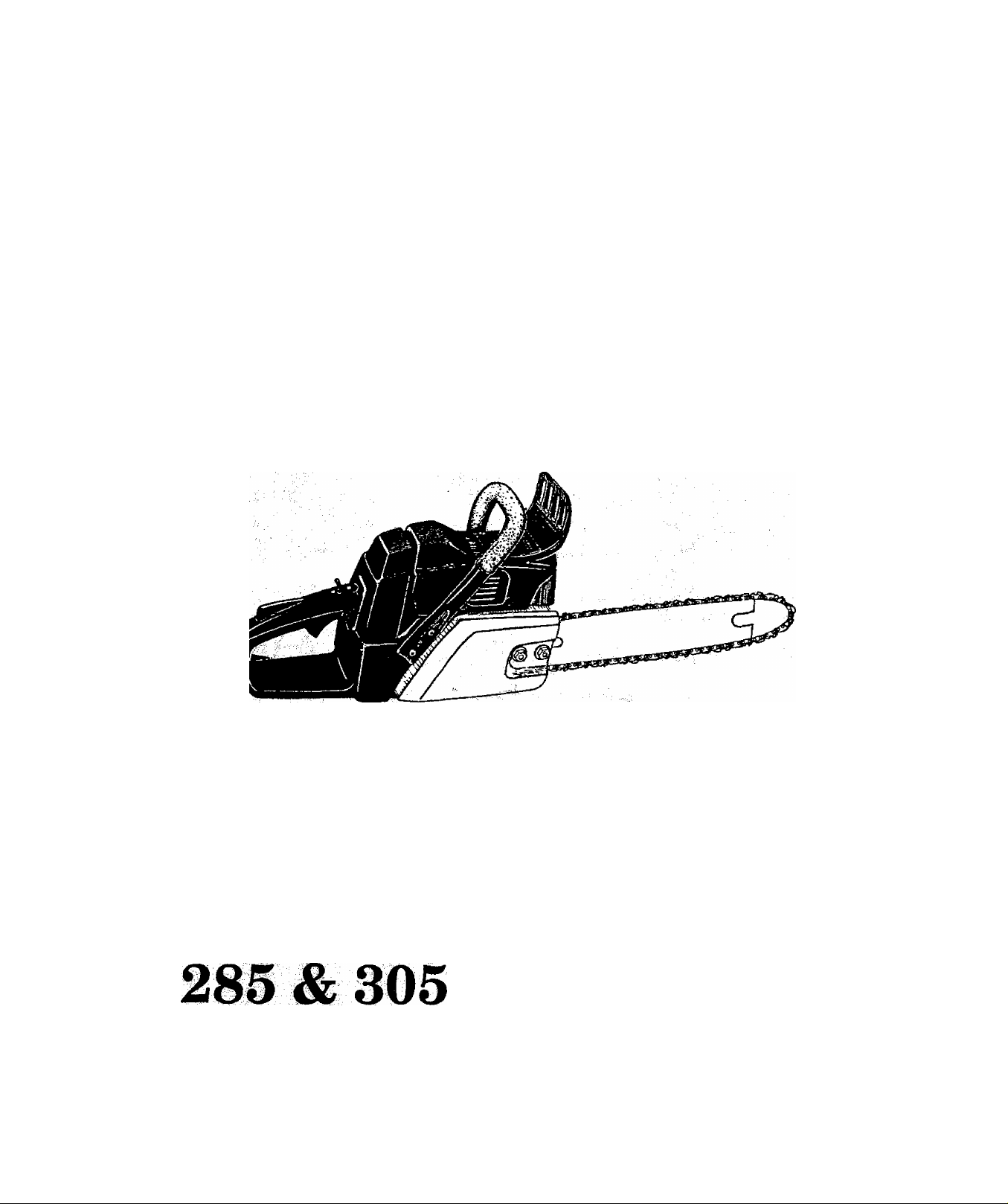
POULANPRO
^tooyeport, 71139^9329
A WARNING:
Ca^fully i^ad the Operator's Manual
an4 follow all Warnings and Safety lU'^
stiinctionsv to do SO cap x’esult
in seHous
Always Wear Eye Protectioii
m
Page 2

TABLE OF CONTENTS
SPECmCATIONS r . . . . / 2
SPECIAL SAFETY SECTION
KNOW YOUR UNIT
ASSEMBLY
A. Getting Ready............... ..
B. Attaching the Spur (Optional)
G. Attaching the Bar and Chain
D. Chain Tension
PREPARING YOUR SÀW FOR USE .
A. Fuel Saffety ... ^¿9
B. Fuel Mixture ....... . ^
0. Usé The Following Only .............. i., 9
D. Do Not ÜseTlie FbÜp^ . ;......... . . ..
E. Howto Mix Fuel and Fill Thnk ................... 9
E Bar and Chain Oil
USINGYOURSAW
A. Pre-Operation Checks
B. Starting Instructions...................................... 11
Throttle Lock
Lock-out
...
Throttle
.................................
..................................................... 7
_____
....
.....
......................................... 11
Handlebar
.............................
........................... 7
............... 7
..................
i.. ; ;
............................
..................
..............
.............
.................
....................................
.......................10
Hand Guard
T Guide Bar
3
..... 6
8
8
9
9
9
11
TYPES OF CUTTING.......................................... 12
A. Basic Cutting Technique
B. Tree Felling Techniques
C. Bucking
D. Debranching and Pruning
GENERAL MAINTENANCE ............... 16
A. Guide Bar and Chain.....................................
B. Spark Arrestor
C. Starter Rope................................................... 18
D. Carburetor AdjiKtments.................................19
E. Air Filter
F. Storage .......................................................... 20
G. Trouble Shooting Chart
H. Maintenance Chart
ACCESSORIES
PARTS & SERVICE
Reduced Kickback
........... 12
............ 12
...................................................
..........................
..........................................
........................................................
................................
.........................................
......................................................
.............................
READ
SPECIAL SAFETY SECTION
FREQUENTLY
Back Cover
14
15
16
17
.20
21
22
23
Starter
Rear
Handle
Oil Gap
Handle
Fuel Cap
Start/Stop
Switch
Choke
Knob
SPECIFICATIONS
MODEL:
DISPLACEMENT:
GUIDE BAR 18”: 18” Guide Bar —Part No. 952-044375
CHAIN 18”: .325 Pitch, P33S-72 — Part No. 952-051321
GUIDE BAR 16”:
CHAIN 16”:
GUIDE BAR 20”:
CHAIN 20”:
SPARKPLUG:
SPARK PLUG GAP.
IGNITION:
MODULE AIR GAP:
OILER:
FUEL MIX:
MUFFLER:
2-
:■ 285 ■ ■ ■
2.8 cu. in. (46cc)
16” Guide Bar—Part No, 952-044372
.325 Pitch, P33S-66 — Pert No. 952-051320
20” Guide Bar — Phrt No. 952-044377
.325 Pitch, P33S-78 — Part No. 952-051322
Champion (C)J-4)
.025”
Solid State
.008” to .014”
Adjustable Automatic
Gaspline/Oil Mixture - 40:1 (see “Fueling Your Engine”)
Temperature Limiting/Spark Arresting
305
3.0 cu. in. (49cc)
Page 3

WARNINGS AND SAFETY INSTRUCTIONS
(See Additional Safety Instructions throug^hout this Manual)
GUARD AGAINST KICKBAGK
^ckback is a dangerous reaction that can lead to serious in
jury. Do not rely only on the safety devices provided with
your saw. As a chain saw user, you must take special safety
recautions to help keep your cutting jobs free from acci-
§
ent or iniuiy.
!^cKback occur when the moving chain con
tacts ^ olnect at the upper portion of the tip of
the goide bar or when the wood closes in and
pincnes the saw chain in the cut. Contact at the
upper portion of the tip of the guide bar can
cause the chain to dig into the object, which
stops the chain for an instant. The result is a
lightning fast j reverse reaction which kicks the
lide bar up and back toward the operator. If the
saw chain is pinched along the top of the guide
bar, the guide bar can be rapidly dnven back to
ward the operator. Either of these reactions cap
cause loss of saw control which can result in seri
ous injury
_______
A KICKBACK WARNING
....
___________________
REDUCE THE CHANCE OF KICKBACK
1.
Recognize that kickback can happen. With a
basic understanding of kickback, you can reduce the
element of surprise which contributes to accidents.
2.
Never let the moving chain contact any object
at the tip of the guide ban Figure 1.
3.
Keep the working area free from obstructions
such as other trees, brandies, rocks, fences, stumps,
etc. Figure 2, Eliminate or avoid any obstruction
that your saw chain cotdd hit while you áre cutting
throu^ a particular log or branch,
4.
^ep your saw chain sharp and properly ten
sioned. A loose or dull chain can increase the chance
of kickback to occur. Follow manufacturer’s chain
shaipening and maintenance instructions. Check
tension at regular intervals with the engine stopped,
never with the engine running. Make sure the bar
clamp nuts are securely ti^tened after tensioning
the cnain.
Begin and continue cutting at full throttle. If
5,
the chain is moving at a slower speed, there is greater
chance for kickback to occur.
Cut one log at a time.
6.
Use extreme caution when re-entering a pre
7.
vious cut.
8,
Do not attempt plunge cuts.
Watch for shifting logs or other forces that could
9.
close a cut and pinch or fall into chain.
lO^Use the Reduced-Kickback Guide Bar and
Low-Kickback Chain specified for your saw;
MAEVTAIN CONTROL
Keep a good, firm grip on the saw with both
1.
hands ^cmen the engine is running and don’t
let go. Figure 3 . A &m grip can neutralize kick-
Clear The
Working Area
Never Reverse
Hand
Positions
Figures
Stand To
The Left
Of The Saw
Elbow
Locked
Thumb On
Under Side
Of Handlebar
hand completely around the rear handle whether
. your
your are right handed or left handed. Keepyourleft
arm straight with the elbow locked.
2. Position your left hand on the front handlebar
so it is in a straight line with your right hand
on the rear handle when making bucking cuts.
Figure 3 . Never reverse right ana left hand posi
tions for any t3pe of cutting.
3. Stand with your weight evenly balanced on
both feet.
4i. Stand slightly to the left ride of the saw to
keep your body from being in a direct line
with the cutting chain. Figure 3 .
5. Do not overreach. You could be drawn or thrown
off balance and lose control of the saw.
6., Do not cut above shoulder height. It is difficult
to maintain control of the saw above shoulder height
^' places the moving chain dangerously close to
yoxu* upper body.
Page 4

WARNINGS AND SAFETY INSITIUCTIONS (continued)
A WARNING
Because a chaiu saw is a higb-sj^d wood-cuttiug tool, special safety precau
tions must be observed to reduce the risk of accidents. Careless or improper use
of this tool can cause serious ipjuiy^
Hearing
Protection
Snug
Fitting
Ciiothing
Safety
Shoes
Figure 4
Safety Hat
Eye Protection
Heavy Duty Gloves
KNOWypUKSAW
1. Read your operator's manual carefully until
you completely understand and can follow all safety
rules, precautions, and operating instructions before
attempting to operate the unit.
Restrict the use of your saw to adult users who
2.
imderstand and can follow safety rules, precautions,
and operating instructions fouhd in this manu;^.
4. Do not attempt to use your chain saw during
bad weather conditions such as strong wind, rain,
snow, ice, etc., or at night.
5. Carefully plan your sawing operation in ad
vance. Do not start cutting tmtif you have a clear
work area, secure footing, and, if you are fellingtrees,
a planned retreat path.
AVOID REACTIVE FORCES
Pinch-Kickback and Pull-In occur when the chain
is suddenly stopped by beingpinched, caught, or by
contacting a foreign object m the wood. This sudden
stopping of the chain results in a reversal of the (bain force
usea to cut wood and causes the saw to move in the opposite
direction of the chain rotation. Pinch-Kickbaek drives
the saw straight hack toward the operator. Pull-In pulls
the saw away from the operator. Either reaction can result
in loss of control and possibly serious injury.
To avoid Pinch-Kickback;
1. Be extremely aware of situations or obstruc
tions that can cause material to pinch the top of or
otherwise stop the chain.
2. Do not cut more than one log at a time.
3. Do not twist the saw as the bar is withdrawn from
an under-cut when bucking.
To avoid Pull-In;
1. Always begin cutting with the engine at full
throttle and the saw housing against wood.
2. Use wedges made of plastic or wood, (never of
metal) to hold the cut open.
PIANAHEIAD
1. Wear protective gear. Figure 4 v Always use
steel-toed safety footwear with non-slip soles; sni^fitting cIothing;beavy-duty, non-slip gloves; eye protiecripn such as imn-fogging, vented ga^es or fac^
screen; an approved safety hard hat; andsound ba^^
riers-^-^ear plugs or mufflers to protc^ your hearing.
Regular users shpuld have bealuig cheijied regularfy
as chain saw noise can damUge hearing
2. Kebp childreih bystanders, and animsds a
minimum of 30 feet (10 Meters) away fromthe
work sp^a. Dp npt allow other people or animals to
he heah^e chain saw when souring or operaringthe
chainsaw.
3.
Do
not^ handde or operate a chaiu saw when
you are fatigued^ iHt oi* bpeet, pr if yOU aro un^
der the ixiiluence of alcohol, d^
tion. You must be in good physical con<htion mid
mentally aleri. Chain saw work is strenuous. If you
have^^^ a^ that ndght he agi^^
strenuous work, check with your doctorhefoie oper
ating a chain saw.
If situations occur which are not covered in thismanual, use ettre and good judgment* Contact your Service
¿eater if " '
4
HANDLE FUEL WITH CAUTION
Eliminate all sources of sparks or flame in the
1.
areas where fuel is mixe^ poured, or stored.
There should he no smoking, open flames, or work
that could cause sparks. Allow engine to cool before
refueling.
2.
Mix and pour fuel in an outdoor area on bare
ground; store fuel in a cool, diy, well ventilated place*
and use an approved, marked container for ail fuel
purposes.
Wipe up all fuel spills before starting saw.
3.
Move at least 10 feet (3 meters) from the liiel-
4.
ingsite before stmi;ingthe engine.
Do not smoke while handling fliel or while op
6.
erating the saw.
Tiirn the engine off and let your saw cool in a
6.
non--combustible area^ not on diy leaves, styaw,
paper, etc. Slowly remove fuel cap and refuel unit.
Store the unit and fuel in an arm where fuel vapors
7.
cannot reach sparks or open flames from water heat
ers, electric motors or switches, furnaces, etc.
Page 5

WARNINGS AND SAFETY INSTRUCTIONS (continued)
OPERATE YOUR SAW SAFELY
1. Do not operate a chain saw that is damaged,
impro]^rly i^usted, or not completely and
seciirmy assembled.
2.
Operate the chain saw only in outdoor areas.
3.
Do not operate saw from a ladder or in a tree.
4,
Position all parts of your body to the left of cut
and away from the saw chain when the engine
is running.
5.
Cut wood on^ Do not use your saw to piy or shove
away limbs, roots, or other objects.
6.
Make sure the chain will not make contact
with any object while starting the engine.
Never tiy to start the saw when the guide bar is in a
cut or kerf
7. Use extreme caution when cutting small size
brush and saplings. Slender matenal can catch
the saw chain and be whipped toward you or pull you
off balance.
8. Be alert for sprin^ack when cutting a limb that
is under tension so you will not be struck by the limb
or saw when the tension in the wood fibers is re
leased.
9. Do not put pressure on the saw at the end of a
cut. Applying pressure can Cause you to lose control
when the cut is completed.
10. Stop the engine before setting the saw down.
MAINTAIN YOUR SAW IN GOOD
WORKING ORDER
1. Have aU chain saw service performed by a qualiHed service dealer with the exception of me
items listed in the maintenance section of this manu
al. For example, if improper tools are used to remove
or hold the flywheel when servicing the clutch, struc
tural damage to the flywheel can occur and cause the
flywheel to burst.
2.
Keep ftiel apd oil caps, screws, and fasteners
securely tightened.
Keep the handles dry, clean, and free of oil or
3.
fuelmixture^
4.
Make certain the saw chain stops moving
when the throttle trigger is released. For cor
rection, refer to “Carburetor Adjustments.”
5.
Stop the saw if the chain strikes a foreign ob
ject. Check for alignment, binding, breakage, and
mounting of moving parts and any other condition
that may affect the operation of the unit. Check
guards and all other parts to see if each will operate
properly and perform its intended function. Any part
that is damaged should be properly repaired or re
placed by using the instructions in mis manual or by
taking your unit to your Authorized Service Dealer.
6. Disconnect the spark plug before performing
any maintenance except for carburetor ac(just-
ments.
7. Never modi^ your saw in any way. Use only at
tachments supplied or specifically recommend^ by
the manufacturer.
8. Always replace the handguard immediately if
it becomes damaged, broken, or is other wise
removed,
CAIUIY AND STORE YOUR SAW SAFELY
1. Hand carry with the engine stoppe^ the
muffler away from your body, and the ^de bar
and chain to the rear covered preferably with a scab
bard,
2. Before transporting in any vehicle or storing
in any enclosure, allow^oursawto cool complete
ly, cover the bar and chain, and properly secure to
avoid turnover, fuel spillage, or damage.
3. Empty the hiel tank before storing the took
Use up the fuel left in the carburetor bv starting flie
engine and letting the engine run until it stops.
4. Store unit and hiel in a dry area out of the
reach of children. Do not store where fuel vapors
can reach sparks or an open flame from hot water
heaters, electric motors or switches, furnaces, etc.
NOTE: Exposure to vibrations through prolonged use
of gasoline powered hand tools could cause blood ves
sel or nerve damage in the fingers, hands, and wrists
swellings. Prolonged use in cold weather has been
linked to blood vessel damage in otherwise healthy
people. If symptoms occur such as numbness, pain,
loss of strength, change in skin color or texture, or
loss of feeling in the fingers, hands, orvmsts, discon
tinue the use of this tool and seek medical attention.
An anti-vibration system does not guarantee the
avoidance of these problems. Users who operate
power tools on a continual and regular basis must
monitor closèly their physical condition and the con
dition of this tool.
NOTICE: Refer to the Code of Federal Regulations,
Section 1910.266(5); ANSI 133,1 (American National
Standard Safety Requirements); and relevant state
------
J —-.i*
come.
to circulation disorders or abnormal
---------------------------------------------------
j.._;—
NOTE; When cutting fibrous material such as palms, pampas ^ass, yucca, etc., clean the cooling system (in-
^ eluding cylinder cooling nhs) after every other refuming.
Page 6

KNOW YOUR UNIT
A. INTRODUCTION
Your saw has been designed with safety in mind and in
cludes the following safety features as standard equip
ment:
• Reduced-Kickback Guide Bar
• Low-Kickback Chain
• , Handguard
• Spark Arrestor
• Temperature Limiting Muffler
• Anti-vibration System
• Turbo Clean"* Air Filter System
A WARNING
The following features aré included on your saw
to he^ reduce the hazard of kickback; however,
such léatures will not totally eliminate this dan
gerous reaction. As a chain saw user, do not rely
only on safety devices. You must follow all safety
precautions, instructions, and maintenance in
this manual to help avoid kickback and other
forces which can result in serious iiijury.
B. KICKBACK SAFETY FEATURES
• RedUced-Eickback Guide Bar, designed with a
small radius tip which reduces the size of the kickback danrer zone on the bar tip. Figure 5. A Redu
ced-Kickback Guide Bar is one which has been dem
onstrated to significantly reduce the number and se
riousness of kickbacks when tested in accordance
with the safety requirements for gasoline powered
chain saws as set by the American National Stan
dards Institute, Inc., Standard B175.1 -1991.
• Low-Kickback Chain, designed with a contoured
depth gauge and guard link which deflect kickback
force and allow wood to gradually ride into the cut
ter. Figure 5. Low-Kickback Chain is chain which
has met kickback perform2mce requirements of
ANSI B175.1 (Safety Requirements for GasolinePowered Chain Saws) when tested on a rejiresentative sample of chain saws below 3.8 cubic inch dis
placement specified in ANSI B175.1.
• Handguard, designed to reduce the chance of your
left hand contacting the chain ifyourhand slips off
the front handlebar.
• Position of front and rear handlebars, de
signed with distance between handles and “in-line”
with each other. The ^read and “in-line” position
of the hands prorided by this design work together
to give balance and resistance in controlling
ot of the saw back toward the operator
occurs.
Caiitourad
Depth Gau^
Etoo^ted
Guard Link
Deflecta
Kidd>adc Force
Baduced Kit^cbedc.
Symmetric&l Guide Bar
Small
BadiuiTip
And Allows Wood
To Gradudl)'
Ride Into Cutter
C. STATE AND LOCAL REQUIREMENTS
Your saw is equipped with a temperature limit
ing muffler and spark arresting screen which
meets the requirements of Caiifomia Codes
4442 and 4443, All U.S. forest land and the states of
California, Maine, Washington, and Oregon require
a spark áriestor screen by law. ^
R you operate a chain saw in a state or locale
where such regulations exist, you axe legaUy re
sponsible for maintaining the operating condi
tion of these parts. Failure to do so is a violation
of the law, l^fer to the **Spark Arrestor** sec
tion for maintenance.
SAVE THESE INSTRUCTIONS
D. CARTON CONTENTS
KEY
m
1.
Engine
Guide Bar
2.
3.
Engine Oil
Operator's Manual (not shown)
Loose Parts Bag (not shown)
LOOSE PARTS BAG CONTENTS:
4. Chain
5, Scrench
E. UNPACKING INSTRUCTIONS
1. After removing the contents from the carton,
check parts against the Carton Contents list.
2. Examine the paries for damage. Do not use dam
aged parts.
3. Nodfyyour PdULAN PJiO dealer immediaiely if
a paH is missing or damaged,
NOTE: It is normal to hear the fuel filter rattle in an
empty fuel tank.
QTY
1
1
1
1
1
Symmetrical
Guide Bar
Large
Radius Tip
Figure 5
Chaio With High
Kiddback Potential
Cao Obstruct
Material
Page 7

A. GETTING READY
1. READ YOUR OPERATOR’S MANUAL
CAREFULIY
Your Operator’s Manual has been developed to help
you prepare your saw fpr use and to understand its
safe operation. It is important that you read your
manual completely to become familiar with the
unit before you begin assembly or attempt opera
tion. Your POULAN PRO dealer is available to
show you how to operate your saw Be sure to ask
for his assistance.
B. ATTACHING THE SPUR (Optional)
The spur is a special piece of equipment de
signed to assist thei cutting operation. When as
sembled to saw, the spur will dig into tree or log and:
• relieve contact pressure adding ease to the
sawing operation.
• allow the saw to be more easily rotated or
pivoted into the cut.
To Install:
1. Remove the bar clamp nuts, bar clamp, and plastic
spacer. Figure 6. Discard plastic spacer.
NOTE; Be sure to remove the plastic spacer on the
bar stud (between bar clamp and crankcase).
2. Remove the isolator bracket screw. Figure?.
3. Remove and discard the spacer under the isolator
bracket. Figure 7.
4. Position the spur over the two holes in the shroud.
Figure 6, Make sure the bottom screw hole tab on
the spur is positioned betw^eh the shroud and the
isolator bracket (where the spacer was removed).
5. Insert the two spur screws and tighten evenly and
securely.
2. HAVE THE FOLLOWING AVAILABLE:
a. Protective gloves.
b. Approved, marked fuel container.
c. One gallon regular unleaded gasoline.
d. 2 (ycle, air-cooled engine oil (See the “Fueling
Your Engine” section).
e. E|ar and Chain Oil (See the “Bar and Chain Oil”
section).
£ Scrench.
Figure 6
Isolator
Bracket
Isolator
Bracket
Screw
Spacer
Figure 7
NOTES
-7-
Page 8

e. ATTACHING THE BAR AND CHAIN
• Your saw is equ^ped with a Reduced-Kick
back Bar and a Low-^ckback Chain.
• Always use the Reduced-Backback Guide
Bar and Low-Kickback Chain specified for
your chain saw model when replacing these
parts. See the “Specifications^ section.
A WARNING
Do not start the engine without the guide bar and
chain completely assembled. Otherwise, the
clutch can come off and serious injury can result.
I CAUnON: I Wear protective gloves when han
dling or operating your saw. The chain is sharp
and can cut you even when it is not moving!
1. Removetheharclampnuts, bar clamp, and ]}}astic
spacer if you have not already done so. Discaard
plastic spacer.
2. Turn the adjusting screw (Fig^ lO) counter
clockwise to move the adjusting pin almost as far as
it will go to the rear.
3. Mount the guide bar imth the slotted end over the
moimting studs. Figi^ 8 . Position the adjusting
pin in the adjusting pin hole. Figure 8.
4. Hold the chain with the cutters facing as shown in
Figure 9 (inset).
5. Place the chain over and behind the clutch drum
and onto the sprocket. Figure 9 . Fit the bottom of
the drive links between the teeth in the sprocket.
6. Slide the ^de bar towaid the rear of the saw as far
as possible.
7. Start at the top of the bar and fit chain drive links
into the groove around the guide bar. Figure 9.
8. Turn the adjusting pin clockwise until the chain is
snug in the guide bar groove. Figure 10.
D. CHAIN TENSION
• Ck>rrect Chaiu Tensipu is very im^rtant—
- A loose chain will wear thè bar and itself
- A loose chain can jtunp off the bar while you are
cutting
- A tight chain can break or damage the saw and/
orbar.
• The chain stretches during use, especi^y
when new. Check tension periodically as follows:
- each time the saw is used;
- more frequently when the chain is nev^
- as the chain warms up to normal operating
temperature.
• Chain tension is correct when the chain:
~ can be lifted about 1/8" from the Guide Bar at a
point near the middle of the bar and
will move freely around the bar.
installing a new chain, allowthe chain to
be lifted 1/4" from the bar. Thereafter, follow the
instructions as indicated.
• Chain tensioning procedure:
I WARNING: i Always wear ^oves when handl-
ihg the chain. The chain is shaxm and can cut
you even when it is not moving!
NOTE; The bar clamp nuts must be no more than
finger tight to tension the chain correctly.
NÓTE; Hold tip of guide bar up through step 4.
1. yft up the tip of the guide bar and turn the adjust
ing screw clockwise until the chain does not sag be
neath the guide bar. Figúrelo.
2. Check the tension by lifting the chain from the
guide bar at the center of the bar. Figure 11.
-8-
9. Hold the guide bar against the saw frame and in
stall the bar clamp,
10, Replace the bar clamp nuts and tighten finger tight
only. Tighten bar clamp nuts after chain is
tensioned.
IL Proceed to the “Chain Tension” section.
ole Above Slot
Bar
Mounting
Studs
Figures
Figure 9
3. Cohtmue adjusting the adjusting Screw until the
tension is correct.
4. Lift up the tip of the guide bar and tighten the bar
clamp nuts with the scrench.
6. Rechecfc chain tension. Figure 11.
Adjusting Screw
Turn To
Increase
Chain
Tension
Figure 10
Figure 11
Adjusting Pin Hole
Turn To
Decrease
Chain
Tension
Page 9

PREPARING YOUR SAW FOR USE
A. FUEL SAFETY
1. Use only recommended fuel mixtures.
2. Mix and pour fuel outdooi^ and where there are
no sparks or flames.
3. Use a container approved for fuel.
4. Do not smoke or allow smoking near fuel or the
tool or while using the tool.
6. Wipe up all fuel spills before starting the engine.
6. Move at least 10 feet away from the fueling site
before starting the engine.
7. Stop the engine before removing the fuel cap.
Allow the engine to cool before refueling.
8. Empty the fuel tank before storing the tool. Use
up fuel left in the carburetor by starting the en
gine and letting it run until it stops.
9. Store unit and fuel in an area where fuel vapors
cannot reach sparks or open flames from water
heaters, electric motors or switches, furnaces,
etc.
B. FUEL MIXTURE
• Your unit is powered by a two-cycle en
gine which requires a fuel mixture of reg
ular unleaded gasoline and a high quality
engine oil specially made for 2-cycle, air
cooled engines. The intemal design of the
2-<ycle engine requires lubrication of moving
parts. Lubrication is provided when the recom
mended mixture of gasoline and oil is used.
• Genuine POULAN PRO 40:1 engine oil is
strongly recommended for the protection
of your unit. Extensive engineering tests have
proven that POULAN PRO oh resists break
down at operating temperatures common to
2-cycle engines, insulting in dependable per
formance and longer engine life.
• Gasoline must be clean and not over two
months old. Gasoline will chemically break
down and form compounds that cause hard
starting and damage in 2-cycle engines.
• Tbe correct measure of gasoline to oil is
very unportant. Too much oil in the mixture
will foul the spaik plug.
GAUTION! \ Too little oil or incorrect oil will
bause the engine to overheat and seize.
f ^ways mix the fuel thoroughly in a con
tainer since gasoline and oil do not readily
combine. Do not mixgasoUne and oil dir&^ly in
the fuel tank,
C. USE THE FOLLOWING ONLY:
POULAN PRO 40:1 engine oil is strongly recom
mended. Any other POULAN PRO, POULAN,
WEED EATER, or PARAMOUNT brand engine oil
is acceptable if mixed according to the instructions
on the container.
If POULAN PRO, POULAN, WEED EATER, or
PARAMOUNT brand oil is not available, use a good
quality, 2-cycle engine oil mixed at a ratio of 16:1 (8
oz. oil to 1 gal. gasoline).
D. DO NOT USE THE FOLLOWING:
• NMMA OIL (National Marine Manufac
turer’s Association)—formerly BIA oil—
Does not have proper additives for air-cooled,
2-<ycle engines and can cause engine damage.
• AUTOMOTIVE OIL—
Does not have proper additives for air-cooled,
2-cycle engines and can cause engine damage.
A WARNING
Alcohol blended fuels (called gasohol or using
ethanol or methanol) can attract moisture which
leads to separation and formation of acids dur
ing storage. Acidic gas can damage the fuel sys
tem of an engine while in storage. To avoid en
gine problems, the fuel system should he emp
tied before storage. Drain the gas tank, start the
engine, and let it lom until the fuel lines and car
buretor are empty Use fresh friel after taMng
the unit out of storage* See the “Storage”^ sec
tion for additional information. Never use en
gine or carburetor cleaner products in the fuel
tank or permanent damage may occur.
E. HOWTO MIX FUEL AND FILL TANK
1. Pour the proper measure of en^ne oil into an
approved, marked fuel container. Thqn, fill the
cxintainer with regular unleaded gasoline.
NOTE: If fuel is already in the container, add the
proper measure of engine oil. Then, close the
container tightly and shake it momentarily.
NOTE: Do not mix gasoline and oil directly in the
fuel tank
2i Using a spout or funnel, fill the fuel tank with
fuel mix.
3. Reinstall ihe fuel cap securely.
NOTES
-9-
Page 10

E BAR AND CHAIN OIL
• The Guide Bar and Cutting Chain require
continuous lubrication to remain in operat
ing condition. Lubrication is provided by theautomatic oiler system when the on tank is kept filled.
— Lack of oil will quickly ruin the Bar and
Chain.
— Too little oil will cause overheating shown
by smoke coming from the chain and/or discol
oration of the guide bar rails.
• GenuinePOULANorPOULANPROBarand
Chmn Oil is recommended to protect your
unit against excessive wear froin heat and
friction. POULAN or POVLAN PRO oU resists
high temperature thinning. If POULAN or
POULAN PRO Bar and Chain Oil is not available,
use a good grade SAE 30 oil. Never use waste oil for
bar and chain lubrication.
e ^ freezing weather oil will thicken, making
it necessary to thin bar and chain oil with a
small amount of #1 Diesel Fuel or kerosene.
Bar and chain oil must be free flowing for the oil
system to pump enough oil for adequate lubrica
tion,
6. USE THE FOLLOWING:
30® or above —100% lubricant — undiluted.
30 °-0 ®F — 95% lubricant to 5% #1 Diesel Fuel or
IcGlTOSOHO
Below 0 ®F—90% lubricant to 10% #1 Diesel Fuel
or kerosene.
;—To decrease the oil flow, turn the oil adjust-
i)^ smew clocliwise.
• K the oiler is adjusted to decrease the oil
flow, be sure to readjust the oiler before returning
• When the saw is run at high speed for long
periods of time during certian types of cut
ting, such as pruning and debrancmng:, more oil
canoe delivered than is required. To avoid running
out of chain oil before running out of fuel, check the
oil tank periodically.
9. IMPORTANT POINTS TO REMEMBER
Fill the oil tank each time you refill the
a.
fuel tanük to ensure that there ^1 be sufflcient
oil for the chain vdienever you start and run the
saw.
Keep sawdust and debris cleaned from
b.
the oil holes in the miide bar to allow an ad
equate oil flow to the bar and chain.
c. ]Efeep spilled and spattered oil wiped from
the unit to avoid sawdust and debris
build-up* P^y particular attention to oil on the
fan housmg and starter assembly to avoid over
heating the engine.
d. It is normal for a small amount of oil to
appear under the saw after the engine
stops. This is excess oil draining from the bar
ana chain when the saw is not in use.
7. HOW TO FILL THE OIL TANK
a.
Stop the engine.
b.
Turn saw on its side with oil cap up. Figure 12.
Loosen cap slowly and wait for pressure in the
c.
tank to be released before removing the cap.
Fill the oil tank.
d.
e.
Replace the oil rap securely.
8. ADJUSTING THE AUTOMATIC OILER
• The adjustable automatic oiler is set for
maximum output at the factory some types
oTcutting vrill rei]pire adjusting the oiler.
-- less oil is required for soft or freshly cut
woo^
r» maximum oil is required for hardwood or
,';V..'time.
• The adjusting screw is located at the bottom of
t^ saw on the crankc^e next to the bar clamp
housing (Figure 13) and can be adjusted with the
screwdriver end of the scrench provided with your
saw. . .
wood that has been cut for a period of
To increase the oil flow, turn the oil a^*usting screw counterclockwise.
NOTES
Pill the Oil Tank
Each Time the
Fuel Tank is
FiUed
Figure 12
Figure 13
-10-
Page 11

USING YOUR SAW
A. PRE-OPERATION CHECKS
Each time before operating; your saw, always:
1. >^Checkoverthe safety rules and precautions
in this manual. Make certain you completely un
derstand and can apply each one.
2. Check protective gear. Always use eye, hearing,
and head protection devices; safety footwear; protec
tive gloves; and snug fitting clothing.
3.
Check the saw for loose bolts, nuts, or fit*
tin^. Tighten, repair, or r^lace paits as necess^.
Tools required are listed in '^Getting Ready” section.
4.
Check the air filter. Clean the filter before
starting the engme. For location, see the “Air Filter”
section.
3. CONTROL DEVICES
Understanding the control devices on your saw
is an important part of learning how to properly
and safely operate the unit.
START/STOP SWITCH
STABT STOP .
Start/Stop
Switch
Trigger
Figure 14
I OFF HALF
I ^ POLL
■ CHOKE
5. P^Check the saw chain. The chain should be sharp
and at the correct tension.
6. Check the fuel tank and oil tank. Both tanks
should be filled.
7. P^Check the handles. Handles should be <hy and
free of fuel mixture and oil.
8. P-^Check weather conditions. Do not use your
saw at night or during bad conditions such as strong
wind, rain, snow; etc.
9. P^Check the work area. Keep children, bystand
ers, and animals a safe distance away from tne work
area when starting or operating the saw—a mini
mum of 30 feet.
1. The Start/Stop Switch is moved forward for the
“Start” position and rearward for the “Stop” posi
tion.
2. The two-position Choke helps to start the saw by
controlling the air flow the the fuel system.
3. The Trigger accelerates and controls the speed of
the engine and is designed to be used with the
throttle lock-out.
4. The Throttle tiocfc-out prevents the trigger from
becoming accidentally engaged. The throttle lock
out must be pressed before the trigger can be acti
vated.
5. The Throttle Lock holds the throttle lock-out and
trigger in position while the engine is being started.
Release the throttle lock after the engine is started
by lightly squeezing the trigger.
C. STARTING INSTRUCTIONS (Refer to the «
A WARNING
Always wear shoves; safety footwear; snugHtting
clptmng; and eye, hearing, and head protection
devices when operating a chain saw.
1. BASIC PROCEDURE
a. Hold saw firmly on the ground as shown in Fig
ure 15 . Make sure the saw clmih is free to turn
without contacting any object.
b. Move Start/Stop Switch to the “Start” position.
Figure 14.
c. Push down on the throttle lock-out, then squeeze
the tri^er. Press and hold down the throttle lock,
then slowly release the trigger.
d. Adjust the choke according to “Starting
Procedure for Varying ConditiohSi ” this pa^.
. e. Hold the front hemdlebar with your left hand and
place your right foot through the rear handle to
stabilize the saw:
f. Pullthestarterropequicklywithyourrighthand.
g. After the engine has started, squeeze the trigger
to release the throttle lock, allowing the engine to
return to idle.
A WARNING
The chain must not move when the engine runs
at idle speed. Refer to the «Carburetor Ac(just-
iiients** section for correction.
h. Stop the engine by moving the Start/Stop Switch
to tne “Stop” position. Figure 14 .
” section for location of controls.)
Hold Front Handlebar
and Place Right Foot
Through Handle
FigurelS
2.
STARTING PROCEDURE FOR VARYING
CONDITIONS
NOTE: Be sure to follow “1. Basic Procedure,” as de
scribed on this page.
For a cold engine:
1. ) Pull choke lever to full choke. Figure 14 .
2. ) Pull starter rope quickly vdth ypur right hand
until engine attempts to start, then push the
choke lever to the half ppsitioh. Figure 14.
3. ) Pull the starter rbpe qmckly with your right
hand until the engine starts. Figure 15.
4. ) Allow the engine to run for approximately five
seconds. Then, push the choke lever to the off
position. Figure 14 . _______.
A WARNING
Avoid bodily contact with the muffler when start-
ihg or using a warm engine to avoid serious bums.
-11-
Page 12

b. For a warm engine:
IJLeave choke lever in off position. Figure 14.
2. ) Pull the starter rope quickly with your right
hand until the engine starts. Figure 15 .
3. ) Stop the engine by moving the Start/Stop
Switch to the “Stop” position. Figure 14 .
c. For a refueled warm engine after running
out of fuel:
1. ) PuU the choke lever to full choke. Figure 14.
2. ) Pull the starter rope quickly with your right
hand until the engine attempts to start.
3. ) Push the choke lever to off. FHgure 14.
4. ) Pull the starter rope quickly with your right
hand imtil the engine starts. Figure 15.
TYPES OF CUTTING
3. IMPOIOVUilT POINTS TO №MEMBER
a. When pulling the starter rope, do not use the
full ^ent of the rope as this can cause the rope to
break. Do not let the starter rope snap back—
hold the handle and let the rope rewind slowly.
b. If the engine floods, let the unit sit for a few
minutes, then repeat starting procedure using the
half-choke position.
c. For cold weather starting, allow the engine to
warm up (1-2 min.) at the half-^hoke position,
then move choke to the“Off” position. Do not cut
material with choke at “Full” or “Half” position.
■K'
A. BASIC CUTTING TECHNIQUE
1. IMPORTANT POINTS
a.
Cut wood only. Do not cut metal* plastics; ma
sonry; non-wood building materials; etc.
b.
Stop the saw if the chain strikes a foreign
object. Inspect the saw ^d repair or replace
p^s as necessary.
c.
Keep the chain out of dirt and sand. Even a
small amount of dirt will quickly dull a chain and
thus increase the possibility of kickback.
A WARNING
Kickback can occur when the moving chain con
tacts an object at the upper portion of the tip of the
guide bar or when the wood closes in and pinches
the saw chsw in the cut. Cont<ict at the upper nor-
tion of the tip of the guide bar can cause the chai
to dig into the object and stop the chain for an in
stant. The result is a lightning fast, reverse reac
tion which kicks the guide bar up and back toward
the operaton If the saw chain is pinched along the
tpp of the guide bar, the guide oar can be drivjen
rapidly back toward ike operaton Either of these
reactions can cause loss of saw control which can
result in serious injury,________________________
stand on uphill side
of tree when cutting.
Begin putting with the
spur égainst the log.
Figure 16
_
2. UNDERSTANDm FORCES
Pinch-kickback and Pull-In occur when the
chain is suddenly stopped by being pinched,
caught, or by contacting a foreign object in
the wood. This stopping of the chain results in a re
versal of the chain force used to cut wood and causes
the sawto move in the opposite direction of chain ro
tation. Either reaction can result in loss of control
and possible serious injuiy.
• Pinch-Kickback—
occurs when the chain on top of the bar is sudden
ly stopped.
— rapidly drives saw straight back toward operator
• PuU-In~
— occurs Tiriien the chain on the bottom of the bar is
suddenly stopped.
— pulls the saw rapidly forward.
3. PROCEDURE
Practice cutting a few small logs using the following
technique to get the “feel” of using your saw before
you begin a m^'or sawing operation.
a. Accelerate engine to full throttle before
entering cut by squeezing the throttle trigger.
b. Begin cutting with the saw frame against
the lo^ Figure 16.
c. Keep the engine at full throttle the entire
time you are cutting.
d. Allow the chain to cut for you; exert only light
downward pressure. If you force the cut, dam^
to the bar, chain, or engine can result.
e. Release the throttle trigger as soon as the
cut is completed, allowing the engine to idle. K
you run tiie saw at full throttle without a cutting
load, imnecessaiy wear can occur to the chain,
bar, and engine.
f To avoid losing control when cut is complete, do
not put pressure on saw at end of cut.
g. : Stop the engine before setting the saw down af
ter cutting.
ST^EFELLI^
1. CAREFULLY PLAN YOUR SAWING OPERA-
TtONINAD
a. Clear the work area. You need a clear area all
at all times.
b.
Study the natural conditions that can cause
the tree to fall in a particular direction.
1. ) The WIND direction and speed.
2. ) The LEAN of the tree. The lean of a tree
-12-
might not be apparent due to uneven or slop-
ing tenain. Use a plumb or level to determine
the direction of tree lean.
3. ) WEIGHTED and BRANCHES on one side.
4. ) Surrounding TREES and OBSTACLES.
c.
Look for decay and rot. If the tnink is rotted, it
can snap and fail toward the operator.
d.
Check for broken or dead branches which
can fall on you while cutting.
Make sure there is enough room for the
e.
tree to fall. Maintain a distance of 2 1/2 tree
lengths from the nearest person or other objects.
Engine noise can drown out a warning call.
Page 13

£ Remove dirt, stones, loose bark, ii^^, sta
ples, and wire from the tree where cuts are
to be made.
g^. Plan to stand on the up-hill side when cut
ting on a slope. Figure 17.
h. Plan a clear retreat path to the rear and di
agonal to the line of fall. Figure IS.
2.
FEtONG SMALL TREES--LESS THAN
6” IN DIAMETER
If you know the direction of fall:
a.
1. ) Make a single felling cut on the side away from
the direction of fall.
2. ) Cut all the way through,
3. ) Stop the saw, put it down, and get away quickly
h.
DO NOTCIJK A WARNING
—near electrical wires or buildings.
--if you do not know the direction of tree fall.
--St night since you will not be able to see well.
—during bad weather — rain, snow, strong
wind, etc.
3. FELLING LARGE TREES—6” IN DIAMETER
OR MORE
The notch method is used to fell largje trees. A notch
is cut on the side of the tree in the desired direction of
fall. After a felling cut is made on the opposite side of
the tree, the tree will tend to fall into the notch.
NOTE; If the tree has large buttress roots, remove
them before making the notch. Cut into the but
tresses vertically, then horizontally. Figure 19,
a. Make the notch cut. Figure 19 .
b.
c.
NOTE; The hinge helps to keep the tree from twist
ing and falling in the wrong direction,
d. Use a wed№ if there is any chance that the tree
on your planned retreat path.
If you are not sure which way the tree will fall, use
the notch method described for felling large trees.
1. ) Cut the bottom of the notch first, througdi 1/3
of the diameter of the tree.
2. ) Complete the notch by niaking the slant cut.
3. ) Remove the notch of wood.
Make the felling cut on the opposite side of the
notch about 2” higher than the bottom of the
notch.
Leave enough uncut wood between the felling cut
and the notch to form a hinge. Figure 20.
will not fall in the desired direction.
A WARNING
Stay on thè uphill side of the terrain to avoid in
jury from the tree rolling or sliding downhill af
ter it is felled. Figure 18 .
NOTE; Before the felling cut is complete, use wedges
to open the cut when necessary to control the direc
tion of fall. Use wood or plastic wed^s, but never
steel or iron, to avoid kickback and chain damagCr
DON’T PUT YOURSELF IN THESE POSITIONS
e. Be alert to signs that the tree is ready to fall:
1. ) Cracking sounds,
2. ) ^dening of the Felling Cut.
^ 3.) Movement in the upper branches.
f. As tree starts to fall, stop thesaw,piait doiun^ and
vei away quickly on your planned retreat path.
g. Be extremely cautious "mth partially fallen trees
that msy be poorly supported. When a tree
doesn’t fall completely, set the saw aside and pull
down the tree with a cable winch, block and
taclde, or tractor. To avoid ixquiy, do not cut down
a partially fallen tree with your saw.
Cut
Buttress
Roots
First
Stay On Uphill Side Of
Tree When Felling
Figure 17
Direction
.............
Figure 19
Direction
OfFhil
Closing
Of Notch
Hin^ Holds Tree On Stump And Controls Fhll
Figure20
________
Figure 18
Opening Of
Felling Cut
Check the wind—
Don’t cut down wind
Check the —
Don’t cut on leàn side
Check the balance—
Don’t cut on weighted side
-13-
Page 14

aBucKiNa
Bucking is the term used for cutting a fallen
tree to the desired log size,
1. IMPORTANT POINTS
a.
Cut only one log at a time.
Cut shattered wood veiy carefolly. Sharp
b.
pieces of wood could be flung toward the operator.
c.
Use a sawhorse to cut small logs.
Never allow
another person to hold the log while cutting and
never hold the log with your leg or foot.
d.
Bo not cut in an area where logs, limbs, and
roots are tangled such as in a blown down
area. Bre^ the logs into a clear area before cut
ting by pulling out exposed and cleared logs first.
Make the first buckihg cut 1/3 of the way
e.
through the log and HmsH with a 2/3 cut on
the opposite side. As the log is being cut, it will
tend to bend. The saw can become pinched or
himg in the log if you make the firet cut deeper
than 1/3 of the diameter of the log.
f. Give special attention to logs under strain
to prevent the saw from pinching. Make the
first cut on the pressure side to relieve the stress
on the log. Figure 21.
2. TYPES OF CUTTING USED {Figure 22):
— Overcutting — begin on the top side of the log
with the bottom of me saw against the log; exert
light pressure downward.
— Undercutting—begin on the imder side of the
log with the top of the saw against the log; exert
li^t pressure upward. During undercutting, the
saw will tend to push back at you. Be prepared for
this reaction and hold the saw firmly to maintain
control.
AWARNING
Never turn the saw upside down to undercut. The
sjftw cannot be contr<med in this position.
_____________
Figure 22
Figure 23
B-
Cut
Undercut
Wedge Used To
Hold Cut Open
2"^ Cut
A WARNING
If saw becomes pinched or hung in a log, don^t try
to forae it out. You can lose control of the saw re
sulting in i^ury and/or damage to the saw. Stop
thé saw, drive a wedge of plastic or wood into the
cut until the saw canbe removed easily. Figure 23.
Réstart the saw and carefully reenter thè eut. To
avoid kickback and chain damage, do not use a
metal wedge. Do not attem]pt to restart your saw
when it is pinched or hung m a log.
3. BUCKING WITHOUT A SUPPORT
a. Overcut with a 1/3 diameter cut.
b, Roll log over and finish with an overcut.
l^lCut
Pressure Side
2*^*^ Cut
1®* Cut Pressure Side
^ y,(
____
Figure 21
-14-
Using Another
Log As A Support
Figure 24
Page 15

4. BUCKING USING ANOTHER LOG AS
A SUPPORT
a. In area A:
1. ) Undercut 1/3 of the way throu£^ the log.
2. ) Finish with an overcut.
b. In area B:
1. ) Overcut 1/3 of the way throi^h the log.
2. ) Finish with an undercut.
6. BUCKING USING A STAND
a. In area A:
1. ) Undercut 1/3 of the way through the log.
2. ) Finish with an overcut.
b. In area B:
1. ) Overcut 1/3 of the way throi^h the log.
2. ) Finish with an undercut.
D. LIMBING AND PRUNING
A WARNING
Do not stand on the log being cut* Any {k»rtion
can roll causing loss of footing and controL
Use Common Sense
Maintain Secure Footing
• Work slowly, keeping both hands firmly
gripped on the saw. Maintain secure footing and
balance.
• Watch out for springpoles. Use extreme caution
when cutting small size limbs. Slender material may
catch the saw chain and be whipped toward you or
pull you off balance.
• Be xdert for springback. Watch out for branches
that are bent or under pressure as you are cutting to
avoid being struck by the branch or the saw when the
tension in the wood fibers is released.
• Keep a clear work area. Frequently clear
branches out of the way to avoid tripping over them.
AWARNING
Never climb into a tree to limb dr pnme. Do not
stand on ladders, platforms, a log, or in any posi*
tidn which can cause you to lose your balance or
control of the saw.
1. LIMBING
a. Always limb a tree after it is cut doum. Only
then can limbing be done safely and properly.
b. Leave the larger limbs imderheath the
felled tree to support the tree as you work.
c. Start fd the base ofthe felled tree and work
toward the top, cutting branches and liinbs. Re
move small limbs with one cut- Figure 26.
4- Keep the irpe between you and the chain.
Cut from the side of the tree opposite the brmich
you are cutting.
e. Remove larger, supporting branches with
the 1/3/2/3 cutting techniques described in
2. PRUNING
a. Limit pruning to limbs shoulder height or
below. Do not cut if branches are higher than
your shoulder. Get a professional to do the job.
h. Refer to Figure 27 for the pruning tech
nique.
1. ) U ndercut 1/3 of the way through the limb near
the trunk of the tree.
2. ) Finish with an overcut farther out from the
trunk,
3. ) Keep out of the way of the falling limb.
4. ) Cut the stump flush near the trunk of the tree.
AWARNING
Be alert for and guard against kickback. Do not
allow the moving chain to contact any other
branebes or objects at the nose of the guide bar
when lithbing or pruning. Allowing such contact
can result in sermus iiqnry.
Figure 26
I** * *11 V ^2T
W j| i * 11 j Second Pruning Cut
Third Pruning Cut
iSI
1.) Undercut 1/3 of the way through the log.
2i) Finish Twth an overcut.
£ Always use an overcut to cut small and
freely hanging limbs. Undercutting could
cause hmbs to faS and pinch the saw.
First Pruning Cut
Figure 27
-15-
Page 16

GENERAL MAINTENANCE
A good maintenance program of regular inspection
and care will increase the service life and help to main
tain the safety and performance of your saw.
• Make all aiiyustments or repairs (except car
buretor a^ustments) with:
— spark plug wire disconnected.
— engine cool as opposed to a saw that has just
been run.
A. GUTOE BARAND CHAIN
Increase the service life of your Guide Bar and
Chain by;
— Using the saw properly and as recommended in this
—- Maintaining correct chain tension, page 8.
— Proper lubrication, page 10.
—• Regular maintenance as described in this section.
1, CHAIN MAINTENANCE
• Sharpen the chain when:
--wood chips are small and powdery.
Wood chips made by the saw chain should be
about the size of the teeth of the chain.
— saw has to be forced through the cut.
— saw cuts to one side.
I CAUTlONi I Always wear gloves when handling the
chain. The chain can be sharp enough to cut you
even though it is too dull to cut wood.
a. SHARPENING INSTRUCTIONS
Items required:
Gloves
4.5mm Diameter File
Flat File
Depth Gauge
6” File Holder
1. ) Stop the engine and discohnect the
sparkplug.
2. ) Adjust the chain for proper tension. Page 8.
3. ) Work at the midpoint of the bar, moving the
chain forward by hand as each cutter is filed.
4. ) Sharpen Cutters.
a.) Position the file holder level at a 10
angle on the top plate of the cutter and
depth ^uge. Figure 28.
h.) Align the 25® file holder marks with the
bar and parallel to the center of the chain.
Figures 29 & 31.
NOTE; If your file holder has a 30 ® markj disre
gard this mark and file at a 25® angle.
c. ) File from inside toward outside of cutter,
straight across on forward stroke in one
direction only. Use 2 or 3 strokes per cuttingedge. FigureSO.
d. ) Keep all cutters the same length. Fig
ure 30 .
e. ) File enough to remove any damage to the
cutting edges (side plate add top plate) of
the cutter. Figure 30.
f. ) File chain to meet specifications shown in
Figure 31.
A WARNING
Maintain the proper hook angle accordingto the
ni^ufacturer*» specMcation for the chain you
using. Too much hook angle will increase the
chj^c^ of kickback which can result in serious
iidury« Figures 31 & 33 .___________________
16-
• Check saw for loose bolts, screws, nuts, and
fittings regularly. Loose fasteners can cause an
unsafe condition as well as damage to your saw.
Have all chain saw service performedi by a quali
fied service dealer other than the items listed in
the maintenance section of this manual.
File Holder
Cutters
Same Length
1 1^ 1
A WARNING
Depth Gauge
Figure 28
Figure 29
Remove Damage
r^/ \
{o\ Ш
Side Plate Top Plate
Figure 30
Figure 31
Figure 32
5.) Correct bepth Gaug^
a. ) Kace depth eaph cutter
depth gauge. Figure 32 .
b. ) File depth gauge with a flat file until it is
level with the top of the depth gaii^ tool.
c. ) Maintain rounded front comer of depth
gauge with a flat file. Figures 32 & 33 ,
NOTE: The veiy top of the depthgauge should be
fiat with the front half rounded off with a flat file.
Page 17

llie, Pepth Gauge Tool is reouired to insure prop
er d^jptli gauge. Filing the depth gauge too deep
wRl increase the chance of nckhack which can
rijsiilt in serious injury.
b. CHAIN REPLACEMENT
1. ) Use only the Low-Kickback replace
ment chain speciRed for your saw in
the **Specifications** section.
2. ) Replace the chain when cutters or
links break.
3. ) Scie a quailed sendee dealer to re-
S
by a qualified service dealer when in
stalling a new chain to avoid excessive
wear to the chain.
A WARNING
_______________
lace or sharpen your chain.
Iways have a worn sprocket r^laced
2. GUIDE BAR MAINTENANCE
• Conditions which can require ^zide bar
maintenance:
— saw cuts to one side.
—: Saw has to be forced throu^ a cut.
-- inmlequate supply of oil to bar and
chain.
• Check the condition of the ^lide bar each
time the chain is sharj^ned. A worn guide
bar wdl damage the chain and m8ike cutting
more difficult.
• Replace the guide bar when:
— the inside groove of guide bar rails is worn.
— the guide bar is bent or cracked. See Fig
ure 35.
• Use only the replacement Reduced-Kick
back Guide Bar specified for your saw in
the “Specification’* section.
a. Remove the guide bar to service.
b. Clean the oil holes at least once after eveiy
five hours of operation.
c. Removal ^wdust from the gmde bar groove
periodically with a putty knife or a wire. Fig
ure 34,
d. Reniove burrs by filing the side edges of the
guide biiir grooves square with a flat file. Fig
ure 35 .
e. Restore square ed^s to an uneven rail top be
filing with a flat file. Figure 35 .
HookAn^e
L
--------
/—Cjn
io_o
Right Way
Remove Sawdi^t
From Guide Bar Groove
.025-
Rounded / 1
o.n«r (QXiD 1
r
Figure 33
Figure 34
¥
Correct
Guide Bar Worn Grooves
Groove
R
Figure 35
_________
Too Much Squared
Hook Angje^^ Off Comer
Wrong Way
1
¥
i
File Edges
Square
B. SPARK ARRESTOR
__• Carbon deposits build up on the spark arres-
toras the saw is used and must be removed to avoid
creating a fire hazard or causing engine damage.
• Replace the spark arrestor if breaks occur.
• ^ep the spark arrestor clean at 8Á1 times.
Clean: —as required.
—at least once for each 25-30
hooirisf of operation.
Items required: wire brush, 3/8” wrench
1, Disconnect the spark plug wire.
the muffler cover screws and washers.
Remove the muffler cover. Figure 36.
3 iftemove the spark arrestor screen. Figure 36.
4. Clean the screen with a wire brush or replace if
breaks are found.
5. Reassemble parts.
Muffler
Cover
Screws
Muffler
Cover
Washers
Figúrese
HtLAl)
SPECIAL SAFETY SECTION
FREQUKN’M.Y
Spark Arrestor Screen
-17-
Page 18

с. STARTER ROPE
• Replace a broken starter or a rope that is
NOTE: A recoil spring lies beneath the pulley and
is under tension. If the recoil spring is dis
turbed» considerable time and effort will be
required to reinstall. For this reason you may
want to let a qualified service dealer handle this re
pair. If^ou try to repair the starter rope and the re-
coil spimg pops out, take the imit to your dealer.
A WARNING
Always wear eyi^rotection when servicing the
£id;a^er rope. The recoil spring beneath the
pulley is imder tension. If the spring pops out, serjoiis ipjury can result.
1. Remove the four screws on the side of the fan
housing. Figure 37.
I CAUTION! I
housing screws with the black-colored cyl
inder shroud screws. Other than color, these
screws are similar in appearance; but if in
terchanged, they can stnp out and/or cause
permanent engine damage.
2. Remove the fan housing.
3. If the starter rope is not broken, release the
spring tension by pulling about 10 inches of rope
from the pulley as shown in Figure 38. Catch
the rope in one of the notches. Figure 38.
4. Carefully turn the pulley coimterclockwise until
the spring tension is released.
5. Remove the pulley screw in the center of the
pulley. Be sure to note the position of the cam
when removing it from the pulley, Fi^ire 39.
6. Lift the pulley carefully while gently twisting it
counterclockwise.
7. Remove the rope retainer screw and remove the
old rope. Figure 39.
8. Move away from the fuel tank and melt the end
of the rope to be installed.
9. Allow the melted end to drip once. Then, while
the rope is still hot, pull the melted end through
a rag to obtain a smooth, pointed end,
10. Insert one end of the rope through the handle
and secure with a knot. Leave a ЗЛ 6''pigtail be
hind the knot. Figure 40 (inset).
11. Feed the rope through the round starter rope
hole in the fan housing. Figure 39 .
12. Guide the rope inside the pulley then up
through the pulley hole (on the pulley ratchet
side). Figure 39 . It might be necessaiy to in
sert a smmi screwdriver through the underside
hole to push the rope through the pulley hole.
Figure 39 (inset).
13. ^e a knot in the end pfthe rope leaving no more
than 3/8 to 1/4 inch tail and pull the iaiot snuglv
into the corner of the groove in the pulley. Pull
the rope tightly.
14. Tuck the tail on the rope knot into the inner
curved section to avpia iaterference with the
flywheel.
15.
engage the spring.
16. Replace and tighten the pulley screw. Make sure
the starter dog, retainer, cam, and wave washer
are positioned and installed properly. Fig
ure 39.
NOTE; Make sure the cam is installed on the
starter dog in the direction shown in Figure 39 ,
Also, make sure the wave washer is seated
around the top outer edge of the retainer and
not caught between the top of the retainer and
the pulley screw.
-18-
Do not mix chrome--colored fan
17. Puh outiO uxchesofrope. Catch tlmrc^e inthe
slotm thepiillpy Figure40V^ ^^^^^^
is. Turn the pulley cìocl^sé to wind up thè sprmg
until it will turn no more without forcing, tibia
the pulley by hand. Do not Ut go of the pulley.
Let the pulley slowly unwind one full turn and
release the rope from the slot. Continue to hold
thè pulley.
19. Hold the pulley and pull the starter rope to the
full extent of length. Let the rope rewind slowly.
20, Reinstall the fan housing using the chrome-co
lored screws. Tighten the screws securely.
Remove Ghrome Colored Screws
(See Caution linder Step 1)
Figure 37
Turn Pulley
Counterclockwise
To Release
Tension
Figure 38
Pulley Screw
Cam
Starter
Starter
Rope Hole
Figure 39
Figure 40
Wave Washer
Retainer
Page 19

I^IIARBURETOR ADJUSTS
• Poor eni^é performance can be a result of
other causes such as dirty air filter, carbon
bldld-up on muffler outlets, etc. See the
**lVouble Shooting Chart** before proceed
ing with carburetor adjustments.
• For best results, it is recommended that you
have a qualified service dealer make all car
buretor su^ustments. Your dealer has the train
ing, experience, and tools necessary to properly ad
just you saw to meet our factory performance speci
fications. Ì^isseruicc is reoi cowered èyicammJiy. If
it becomes necessary for you to make carburetor
a^* *ustments yourself, follow the described proce
dures very carefully.
• The cwburetor has been adijusted at the fac
tory for sea level conditions. Adjustments may
become nwessaiy if the saw is used at significantly
higher altitudes or if you notice any of the following
conditions:
NOTE; Be sure to properly prepare the saw as de
scribed in “1. Preparation” (below) before making
any adjustments.
— Chain moves when the engine runs at idle speed.
See **2. Idle Speed Adjustment.”
— Saw will not idle. See “2. Idle Speed Adjust
ment” and “3. Low Speed Mixture Adjust
ment.”
■— Engine dies or hesitates when it should acceler
ate. See “4. Acceleration Adjustment.”
— Loss of cutting power which is not corrected by
air filter cleaning. See “5. High Speed Mixture
Adjustment.”
I CAVTfQNlJ perm^ent damagé will occur to
any 2-cycle engine if incorrect carburetor
aijgustments are made.
• If the unit will not operate properly after
makmg these acljustments, take the saw to a
qualified service dealer.
A WARNING
The chain will be moving during most of this pro
cedure. Wear your protective gear and observe
all safety precautions.
1. PREPARATION
a. Stop the engine.
b. Use a fresh fuel mixture with proper gasoline/oil
ratio,
c. Place the saw on a solid, flat surface and make
sure the chain will not contact any object.
d. Locate the three (3) carburetor adjusting screw
openings to the right of the air filter cover. Fig
ure 41.
e. Start the engine and allow engine to idle three
(3) minutes to wann up. The en^Tie must be at
operating temperature for proper adjustrnents to
oeniade.
Idle Speed
Screw'
Figure 41
Low Speed
Mixture
Screw
2. IDLE SPEED ADJUSTMENT
a. Allow the engine to idle.
b. Adjust the Idle Speed Screw imtil the engine
continues to run without stalling and without
the chain moving.
— Turn screw cUxkwise to increase engine
speed if engine ataUs or dies,
— Turn screw coimterclockwise to slow en^ns
down andfor to keep the chain from turning,
c. No further adjustments are necessary if
the chain does not move at idle speed and
if performance is satisfactory.
A WARNING
In Low Speed Mixture Adjustment,** recheck
idle speed ^ter each adjustment. The chain
must not move at idle speed.
3. LOW SPEED MIXTURE ADJUSTMENT
a. Allow engine to idle.
b. Turn the Low Speed Mixture Screw slowly
clockwise until the RPM starts to drop. Note
the position.
c. Turn the Low Speed Mixture Screw slowly
counterclockwise until the RPM speeds up and
starts to drop again. Note the position.
d. Set the Low Speed Mixture Screw at the mid
point between the two positions.
4. AGCELERATION ADJUSTMENT
If the engine dies or hesitates instead of accelerat
ing, turn the Low Speed Mixture Screw 1/16 of a
turn at a time counterclockwise until you have
smooth acceleration.
5. HIGHSPEED MIXTURE ADJUSTMENT
I
CAUTION; j Adjustments as small as 1/16 of a
turn can afiect engine performance. It is im
portant to turn the screw only 1/16 of a turn
per adjustment and test the performance of
the saw before making further adjustments.
a. Make a test cut.
b. Adjust the High Speed Mixture Screw 1/16 of a
tipn as folloyi^:
-— Clockwise if saw smokes or loses power.
— Counterclockwiseifthesawhas speed out of
the cut but lacks power in the cut.
c. Repeat test cut.
d. Continue 1/16 of a turn adjustments imtil the
saw runs smoothly in cut.
I CAUTION; I
(clockwise adjustment) will cause engine
damage to any 2-cycIe engine from over
heating and lack of lubrication. Never set
idle h^h speed mixture screw so ^r clock
wise that you have high speed but lack pow
er while cutting. An effective approach fol
lows,
T— Turn screw counterclockwise until engine loses
powerwhile cutting.
crements ouZy imtil the engine has power while
cutting
NOTO; If the unit will not operate properly after
^ngthese a^ustments, take the sawto a quaUfied service dealer.
A too lean high speed setting
turn screw clockwise in 1/16 of a turn in
-19-
Page 20

E. AIR FILTER
• A dirty air filter:
— reduces cutting power.
— increases fuel consumption.
• Clean the air filter as follows:
— check filter after eveiy 10 tanks of fuel or 5
hours of operation, whichever is less.
— more frequently in very dusty conditions.
1. Clean off carburetor cover and the area around it.
2. Pull the choke to the full position to prevent dirt
from entering the carburetor.
3. Remove the carburetor cover. Figure 42,
4. Carefully remove the air filter.
5. Remove the single air filter screw and separate the
two halves.
I CAUTfQ£jlJ Do not úse gasoline or other flam
mable liquid to clean the filter to avoid
creating a fire hazard.
6. Wash the filter in soap and water.
7. Brush away all dust and debris from the filter.
8. Allow the filter to diy.
9. Reassemble the filter.
10. Brush away all dpt and debris from the surfaces bn
vdiich the filter is to be placed.
11. Reinstall the filter and carburetor coven
1 CAyUQSbJ To avoid damage to the eng^e, do
not operate the unit without the air mter in
place.
Figure 42
F. CLUTCH AND DRUM/SPROCKET
A WARNING
Do not start the engine without the guide bar,
chain, and bar clamp housing comjmetely as
sembled. The clutch can come ofl without the
guide bar and chain completely assembled, and
serious ipjury can result. The clutch shoes and
drum can separate causing the clutch to violent-
ly fly apart and serious iigury can result.
Take the saw to your Authorized Service
Dealer for full clutch inspection and service
after each 100 hours of operation. Itis remm-
mended that you do not tr^sy to service the clutch or
drum!^rocket yourself unless you are a competent
small engine mechanic and have the proper clutch
Service tools. Proper disassembly and repair of the
clutch is extremely important to the life of the en
gine and the safety of the operator.
Inspect the sprocket regularly for wear. A
worn sprocket will make the chain rim erratically
and will shorten the life of the bar and chain. Fig
ure 43.
G. STORAGE
When your saw is to be stored for over 80 days.
Clutch maintenance is required when:
— the chain continues to turn while the engine
idles after the idle speed screw has been
adjusted to its capacity.
— slippage ocisurs during a cut
— a chattering noise occurs during cutting.
Clean the clutch, drum, sprocket^ and sur
rounding area daily during heavy use of the
saw. Check to see that the clutch drum turns freely
and smoothly.
.^ways have a worn sprocket replaced by
your Authorized Service Dealer whenever a
new chain is installed to gain the full life expec
tancy of the chain.
Figure 43
3; Drain oil from oil tank;
1, Drain fuel tank in a safe manner. See “Fueling Your
Engine—Fuel Safety.'’
2. Start engine and allow to run at idle speed until the
engine stops.
NOTE; Running the eni;ine until it stops will re
move most of the fuel from the fuel system,
NOTE; It is important to prevent gum deposits
from formingin essential fuel systems parts such as
the earburetorj fuel filter, fuel nosei or tank during
storage. Alcohol blended fuels (called gasohol or
using ethanol or methanol) can attract moisture
which leads to separation and formation of acids
during storage. Acidic gas can damage the fuel sys
tem of an engine while in storage.
-20-
rCAVTOlMlJ Wear protective gloves when han-
diing the chain. The chain is sharp and can
cut you even yt^en it is not moving:
4, Remove, clean, and dty the bar and chain.
5, Store the chain in a container filled with oil to pre
vent rust.
6, Apply a coating of oil to the en^tire surface of thenar
; and wrap it in heavy paper, cloth, or plastic*
7* Clean the outside surfaces of the engine,
8. Store the saw in a diy place, out of the reach bf chil
dren, and away from where fuel vapors can rbäch
open flames from hot water heaters, furnaces, etc.
Page 21

©.TROUBLE SHOOTING CHART
SYMPTOM CAUSE
Engine will not
start or will run
only for a few
seconds after
starting.
1. Fuel tank empty
2. Engine floods.
3. Spark plug not firing,
4. Fuel not reachin|r carburetor.
5. Carburetor requires adjustment.
6. Ignition Switch Oft
7. None of the above.
Engine will not
idle properly.
1. Idle speed set too fast or too slow.
2. I^wsp^d mixture requires adjustment.
3. Crankshaft seals worn.
4. Compression low.
5. None of the above.
Engine will not
accelerate,lacks
power, or dies
under a load.
1. Air filter dirty.
2. Spark plug fouled.
3. Carburetor requires adjustment.
4. Exhaust ports or muffier outlets plugged.
5. Compression low.
6. None of the above.
Engine
smokes
excessively.
1. Air filter dirty.
2. Fuel mixture incorrect.
3. High speed mixture requires adjustment.
4. Choke partially on.
5. Crankcase leak.
-Engine runs hot. 1. Fuel mixture incorrect.
2. High speed mixture set too low (Lean).
3. Spark plug incoiroct.
4. jSdiaust ports or muffler outlets plug^.
5. Carbon build-up on muffler outlet screen.
6. Fan housing/iyimder fins dirty.
7. None of the above.
REMEDY
1. Fill tank with correct fuel mixture
2. See “Starting Instructions.”
3. Install new^ug/check ignition system.
4. Clean fuel mter; inspect fuel line,
5. See “Carburetor Adjustments.”
6. Move switch to the ^START” position.
7. Contact your Service Dealer.
1. See “Carburetor Adjustments.”
2. See “Carburator Aiyustments.”
3. Contact your Authorized Service Dealer.
4. Contactyour Authorized Service Dealer.
5. Contact your Authorized Service Dealer.
1. Clean or replace air filter.
2i Clean or replace spark plug and re-gap.
3. See “Carburetor Adjustments.”
4. Contact your Authorized Service Dealer.
5. Contact your Authorized Service Dealer.
6. Contact your Authorized Service Dealer.
1. Clean or replace air filter.
2. Refuel with correct fuel mixture.
3. See “Carburetor Adjustments.”
4. Push Choke knob in.
5. Contact your Authorized Service Dealer.
1. See “Fueling Your Unit.”
2. See “Carburetor Adjustments.”
3. Replace with correct plug.
4. Contact your Authorized Service Dealer.
5. Clean spark arrestor screen.
6. Clean area.
7. Contact your Authorized Service Dealer.
Oil inacquate for
bar and chain
lubrication.
Chain moves at
Idle Speed.
Chain does not move
when engine is
acceleial^.
Chain clattei^
or cuts roughly
Chain stops within
the cut.
Chain cuts at an
angle.
1. Oil tank empty.
2. Improperly a^'usted oiler (if so equipped).
3. Oil pump or oil filter clogged.
4. Guide bar oil hole blockedf.
1. Idle speed requires adjustment.
2. Clutch requires repair.
1. Chain tension too tight.
2. Carburetor requires a^ustment.
3. Guide bar rails pinched.
4. Clutch slipping.
1. Chain tension incorrect.
2. Cutters damaged.
3. Chainwom.
4. Clutters dull, improperly sharpened, or
depth gauges too high.
i5. Sprocket worn.
1. Chain cutter tops not filed flat.
2. Guide bar burred or bent; rails uneven.
3. Clutch slipping.
1. Cuttera damaged on one side.
2. Chain dull on one side.
3. Guide bar bent or worn.
1. Fill oil tank.
2. Adjust oiler,
3. Contact your Authorized Service Dealer.
4. Remove bar and clean.
1. See “Carburetor Adjustments.”
2. Contact yoxir Authorized Service Dealer.
1. See “Chain Tension.”
2. See “Carburetor Adjustnients,”
3. Repair or replace.
4. Contact your Authorized Service Dealer.
1. See “Chain Tension.”
2. Contact your Authorized Service Dealer.
3. j^sharpen or replace chain.
4. See the chain sharpening instructions.
5. Contact your Authorized Service Dealer.
1. See the chain sharpening instructions.
2. Repair or repleice guide bar.
3. Contact your Authorized Service Dealer.
1. Resharpen until all cutters have equal
angles and lengths,
2. Resharpen until all cutters have equal
angles and lengths.
3. Replace guide bar.
-21-
Page 22

H. MAiDm:NANCE
1
I
1
I
1
£
E
Complete machine.
Throttle trigger; EWifety throttle lock; stop svritch.
Filter in fuel tank.
Fuel tank.
Chain oil tank.
Chain lubrication.
Saw chain.
Guide bar.
Chain sprocket.
Air filter.
Cylinder fins.
Carburetor
Spark plug.
Ail accessible screws and nuts
(not adjusting screws).
Vibration mounts.
Spark arrestor screen.
Visual inspection (condition, leaks)
Clean
Check operation
Replace pick-up — when clogged or dirty.
Inspect
Clean
Fill
Inspect (sharpness, wear, damage)
Check chain tension
Sharpen — when dull
Inspect (wear, damage)
Clean
Deburr
Replace — when worn or damaged
Check — when replacing chain
Clean
Replace — when worn or damaged
Clean
Check idle adjustment —
chain must not turn at idle
Readjust idle — when engine runs poorly
Replace — when fouled or,damaged
Retighten
Inspect — for broken or disconnected
springs
Replace — when broken
Clean — when clogged or dirty
Replace — when worn or damaged
y*
1
yf
y^
ly
1
1
yy
1
y^
y^
y'
y^
1
ty
ty
§
t
1
I
s
y^
y^
fy
-22
Page 23

See your dealer for accessories and parts.
File - flat - 6"
File - round - 4.5mm - Model 336
Ffle - round - 5/32” - Model 365
Safety Glasses...............................................952-062003
Spark Plug - Model 336............... ^ 952-030120
Spark Plug - Model 365 ....
Fuel & Oil Cap Kit
Air Filter ....................................................
Chain Brake Kit
Reduced Kickback Guide Bar
16*^ ...................-------
20 .................................................... 952-044377
Low-Kickback Chain
16” ..
20”.................................................... ....952-051322
............................................ 952-055027
...............
................
.......................
.....................................
...........................................
-----
...................................................
952-055070
952-055004
952-030164
952-010859
952-014450
952-069356
... 952-044372
952-051320
NOTES
Reduced Kickback Guide Bar - Model 305 Only
18”
......................................................
Low-Kickback Chain - Model 305 Only
18” ...................................................... 952-051321
2-cycle Engine Oil
3.2 oz.-40:l
8 oz.-40:l
Bar & Chain Lubricant
32 oz. __
Igal
.....................................................
Scrench ............V................ 530-034135
Operator's Manual
..............
...........................
___
..................... 952-030129
........................................
.............................
................ 952-030127
952-044375
952-030132
962-030130
530-068802
-23-
Page 24

PARTS AND SERVICE
Vow POULAN PRO product has been expertly engineered and carefully manufactured to rigid
quality standards. As with all mechanicid products, some adjustments or part replacement may be
necessary during the life of your unit.
FOR SERVICE OR REPLACEMENT PARTS:
1. Consult your dealer/place of purchase.
2. Consult the yellow pages of your phone directory for the name of the nearest Poulan/Weed Eater
Master Service DeMer (under “saws” for Chain Saws or under “lawnmowers” for Trimmers, Brushcutters, and Blowers).
3. For replacement parts, have available the following information;
a. Description of the tool.
b. Model Number.
c. Pescription of part.
IVOTE? Poulan/Weed Eater Division provides parts and service throhi^its authorized distributors
and dealers; therefore, all requests for parts and service sho^d be d^ your local
dealer(s). The philosophy of Poulan/Weed Eater Division is to continually improve all of its
products. If the operating characteristics or the appearance of your product differs frpm
those described in this Curator’s Manual, please contact your local Poulan/Weed Eater
PeMcr for npdated iidorhiatidn and assistancCi. Always update your tool when improvements are made available, especially those related to safety. Parts and repair siervice are
not ayaBabie directly from Poulan/Weed Eatei* Piyision of WCI Outdoor Prodncts, Inc;
POULAN/WEED EATER
BmSION OF WClOmBOOB PRODUCTS^ iNG
Shreveport; Louisiana 71139-9329
530-068802-1-06/05/92
©1092 Poulan/Weed Eater Division of WCrOutd(Mr Products, liac.
 Loading...