

Poulan Pro PRGT25H48A Owner's Manual
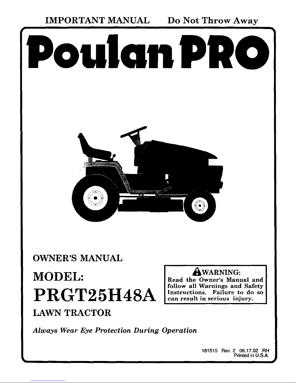
IMPORTANT MANUAL Do Not Throw Away
Poulan
_q
OWNER'S MANUAL
MODEL:
PRGT25H48A
LAWN TRACTOR
_bWARNING:
Read the Owner's Manual and
follow all Warnings and Safety
Instructions. Failure to do so
can result in serious injury.
Always Wear Eye Protection During Operation
181515 Rev. 2 06.17.02 RH
Printed in U.S.A.
SAFETY RULES ^
SAFE OPERATION PRACTICES FOR RIDE-ON MOWERS
IMPORTANT: THIS CUTTING MACHINE IS CAPABLE OF AMPUTATING HANDS AND FEET AND THROWING OBJECTS.
FAILURE TO OBSERVE THE FOLLOWING SAFETY INSTRUCTIONS COULD RESULT IN SERIOUS INJURY OR DEATH.
I. GENERAL OPERATION
• Read, understand,and followatlinstructions inthe manual
and on the machine beforestarting.
• Only allow responsible adults, who are familiar withthe
instructions,tooperate the machine.
Clear the area of objectssuch as rocks, toys, wire, etc.,
whichcould be pickedup and thrown by the blade.
• Be sure the area isclear of otherpeople before mowing.
Stop machine ifanyone entersthe area.
Never carry passengers.
• Do not mow in reverse unless absolutely necessary.
Always look down and behind before and while backing.
• Beaware ofthe mowerdischargedirection and do notpoint
itat anyone. Do not operate the mower without either the
entire grass catcher or the guard inplace.
• Slow down before turning.
• Never leave a running machine unattended. Always tum
off blades, set parking brake, stop engine, and remove
keys before dismounting.
• Turn offblades when not mowing.
• Stop engine before removing grasscatcher or unclogging
chute.
• Mow only in daylight or good artificial light.
• Do not operate the machine while under the influence of
alcohol ordrugs.
• Watch for traffic when operating near or crossing road-
ways.
• Use extra care when loading or unloading the machine into
a trailer ortruck.
• Dataindicates that operators, age 60years andabove, are
involved in a large percentage of riding mower-related
injuries. These operators should evaluate their ability to
operate the dding mower safely enough to protect them-
selves and others from serious injury.
• Keep machine free of grass, leaves or other debris build-
up which can touch hot exhaust / engine parts and bum.
Do not allow the mower deck to plow leaves
or other debris which can cause build-up to occur. Clean
any oil or fuel spillage before operating or storing the
machine. Allow machine to cool before
storage.
II. SLOPE OPERATION
Slopes are a major factor related to loss-of-control and tipever
accidents, which can result in severe injury or death. All slopes
require extra caution. If you cannot back up the slope or if you feel
uneasy on it, do not mow it.
DO:
• Mow up and down slopes, not across.
• Remove obstacles such as rocks, tree limbs, etc.
• Watch for holes, ruts, or bumps. Uneven terrain could
overturn the machine. Taflgrass can hide obstacles.
• Use slow speed. Choose a low gear so that you will not
have to stop or shift while on the slope.
• Follow the manufacturer's recommendations for wheel
weights or counterweights to improve stability.
• Use extra care with grass catchers or other attachments.
These can change the stability of the machine.
• Keep all movement on the slopes slowand gradual Do
not make sudden changes in speed or direction.
• Avoidstartingorstoppingonaslope. Iftireslosetraction,
disengage the blades and proceed slowly straight down
the slope.
DO NOT:
• Do not turn on slopes unless necessary, and then, turn
slowlyand graduallydownhill,if possible.
• Do not mow near drop-offs,ditches, or embankments.
The mowercould suddenlytum overifa wheel isoverthe
edge of a cliffor ditch,or ifan edge caves in.
• Do notmow on wetgrass. Reduced traction could cause
sliding.
• Donottrytostabilizethemachinebyputtingyourfooton
theground.
• Do not use grass catcher on steep slopes.
III. CHILDREN
Tragic accidents can occur if the operator is not alert to the
presence of children. Children are often attracted to the
machine and the mowing activity. Neverassumethatchildren
will remain where you last saw them.
• Keep children out of the mowing area and under the
watchful care of another responsible adult.
• Be alert and turn machine off if children enter the area.
• Beforeandwhenbacking, lookbehindanddownforsmall
children.
• Never carry children. They may fall off and be seriously
injured or interferewith safe machine operation.
• Never allow children to operate the machine.
• Use extra care when approachingblind corners, shrubs,
trees, or other objects that may obscure vision.
IV. SERVICE
• Use extracare inhandlinggasolineand other fuels. They
are flammable and vapors are explosive.
- Useonlyan appreved container.
- Never remove gas cap or add fuel with the engine
running. Allowengineto coolbeforerefueling. Do not
smoke.
- Never refuel the rnachine indoors.
- Never store the machine or fuelcontainer inside where
there is an open flame, such as a water heater.
• Never run a machine inside a closed area.
• Keep nuts and bolts, especially blade attachment bolts,
tight and keep equipment in good condition.
• Never tamper with safety devices. Check their proper
operation regularly.
• Keep machinefree ofgrass,leaves, orotherdebds build-
up.Clean oilorfuelspillage.Allowmachinetocoolbefore
stonng.
• Stop and inspectthe equipment if you strike an object.
Repair, ifnecessary,before restarting.
• Never make adjustments or repairs with the engine
running.
• Grasscatchercomponentsare subjecttowear, damage,
and deterioration,which could expose moving parts or
allowobjectstobe thrown.Frequentlycheckcomponents
and replace with manufacturer's recommended parts,
when necessary.
• Mower blades are sharp and can cut. Wrap the blade(s)
or wear gloves, and use extra caution when servicing
them.
• Check brake operation frequently. Adjust and service
as required.
2
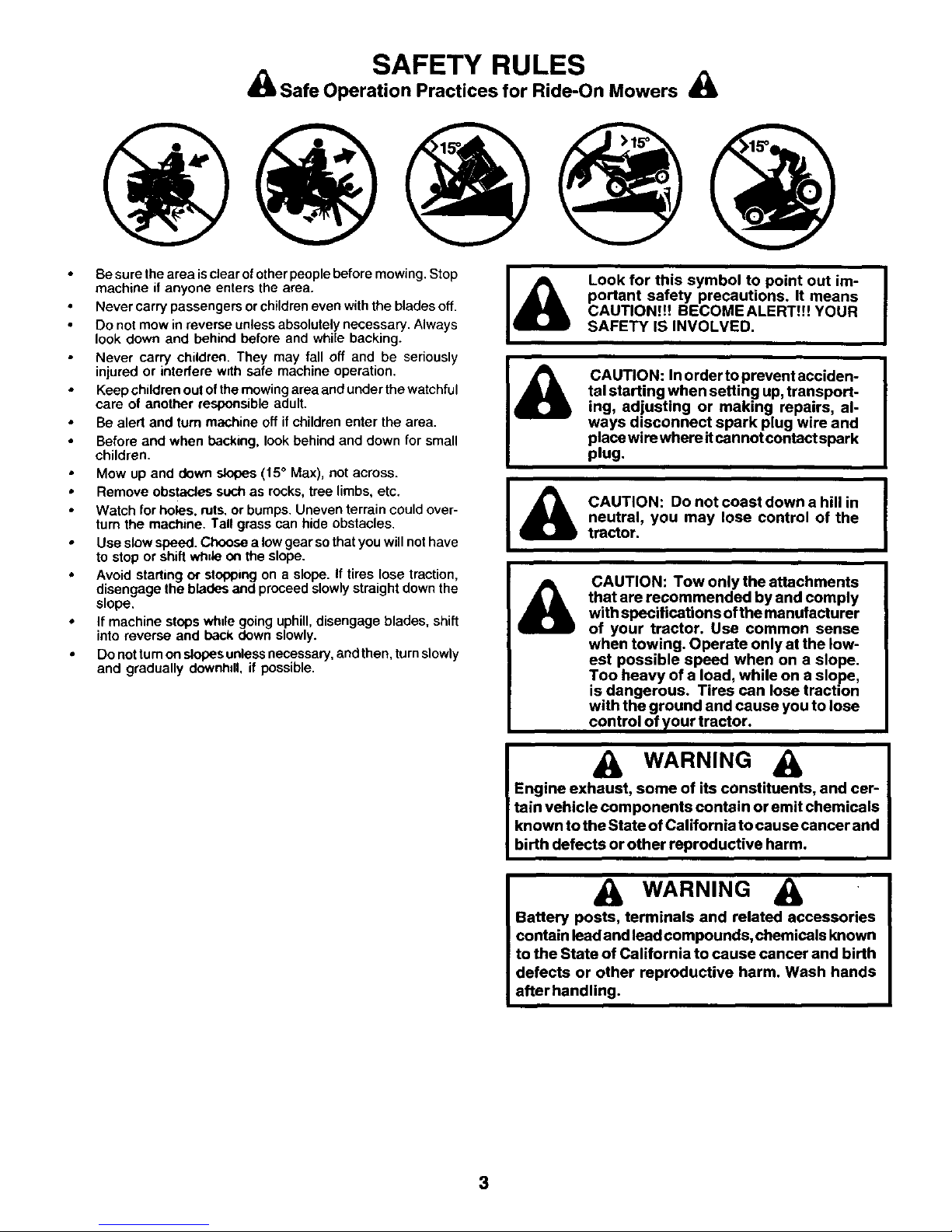
SAFETY RULES
Safe Operation Practices for Ride-On Mowers ,_
Be sure the area isclear of other people before mowing. Stop
machine if anyone enters the area.
• Never carry passengers or children even with the blades off.
Do not mow in reverse unless absolutely necessary. Always
look down and behind before and while backing.
Never carry children. They may fall off and be seriously
injured or interfere wrlh safe machine operation.
Keep children out of the mowing area and under the watchful
care of another responsible adult.
• Be alert and turn machine off if children enter the area.
Before and when backing, look behind and down for small
children.
Mow up and down slopes (15 ° Max), not across.
• Remove obstacles such as rocks, tree limbs, etc.
Watch for holes, nits. or bumps. Uneven terrain could over-
turn the machine. Tall grass can hide obstacles.
• Use slow speed. Choose a low gear so that you will not have
to stop or shift wh_leon the slope.
• Avoid starting or stopping on a slope. If tires lose traction,
disengage the blades and proceed slowly straight down the
slope.
• Ifmachine stops whulegoing uphill,disengage blades, shift
into reverse and back down slowly.
• Do not tum on slopes unless necessary, and then, turn slowly
and gradually downhdl, if possible.
&
Look for this symbol to point out im-
portant safety precautions. It means
CAUTION!!! BECOMEALERT!!! YOUR
SAFETY IS INVOLVED.
CAUTION: In order to prevent acciden-
tal starting when setting up,transport-
ing, adjusting or making repairs, al-
ways disconnect spark plug wire and
place wire where itcannot contact spark
plug.
CAUTION: Do not coast down a hill in
neutral, you may lose control of the
tractor.
CAUTION: Tow only the attachments
that are recommended by and comply
with specifications of the manufacturer
of your tractor. Use common sense
when towing. Operate only at the low-
est possible speed when on a slope.
Too heavy of a load, while on a slope,
is dangerous. Tires can lose traction
with the ground and cause you to lose
control of },our tractor.
WARNING
Engine exhaust, some of its constituents, and cer-
tain vehicle components contain or emit chemicals
known to the State of California to cause cancer and
birth defects or other reproductive harm.
WARNING
Battery posts, terminals and related accessories
contain lead and lead compounds, chemicals known
to the State of California to cause cancer and birth
defects or other reproductive harm. Wash hands
after handling.
3
PRODUCT SPECIFICATIONS
GASOLINE CAPACITY 5.0 GALLONS
AND TYPE: UNLEADED REGULAR
OILTYPE (API-SF-SJ): SAE 30 (above 32°F)
SAE 5W-30 (below 32°F)
OILCAPACITY: W/FILTER: 4.0 PINTS
W/OFILTER: 3.75 PINTS
SPARK PLUG: CHAMPION RC12YC
GAP: .040")
GROUND SPEED (MPH): FORWARD: 0- 5.8
REVERSE: 0-2.1
TIRE PRESSURE: FRONT: 14 PSI
REAR: 10 PSI
CHARGING SYSTEM: 16 AMPS @ 3600 RPM
BATTERY: AMP/HR: 35
MIN. CCA: 280
CASESIZE: U1R
BLADE BOLT TORQUE: 45-55 FT. LBS.
CUSTOMER RESPONSIBILITIES
Read and observe the safety rules.
• Follow a regularschedule inmaintaining, cadng for and
using your tractor.
• Follow the instructionsunder"Customer Responsibili-
ties"and "Storage" sectionsof this owner's manual.
WARNING: This tractor is equipped with an internal
combustion engine and should not be used on or near any
unimproved forest-covered, brush-covered or grass-cov-
ered land unless the engine's exhaust system is equipped
with a spark arrester meeting applicable local or state laws
(if any). If a spark arrester is used, it should be maintained
in effective working order by the operator.
A spark arrester for the muffler is available through your
nearest authorized service centre/department (See RE-
PAIR PARTS section of this manual).
CONGRATULATIONS on your purchase of a new tractor. It has been designed, engineered and manufactured to give you
the best possible dependability andperformance.
Should you experience any problem you cannot easily remedy, please contact your nearest authorized service center/
department We have competent, well-trained technicians and the proper tools to service or repairthis tractor.
Please read and retainthis manual. The instructionswillenable you to assemble and maintainyourtractorproperly. Always
observe the "SAFETY RULES".
TABLE OF CONTENTS
SAFETY RULES ........................................................ 2-3
PRODUCT SPECIFICATIONS ....................................... 4
CUSTOMER RESPONSIBILITIES ...................... 4, 16-19
ASSEMBLY ................................................................ 6-9
OPERATION ......_..................................................... 10-15
MAINTENANCE SCHEDULE ....................................... 16
SERVICE AND ADJUSTMENTS ............................. 20-26
STORAGE ................................................................... 27
TROUBLESHOOTING ............................................. 2829
REPAIR PARTS - TRACTOR .................................. 32-46
WARRANTY ................................................................ 50
4
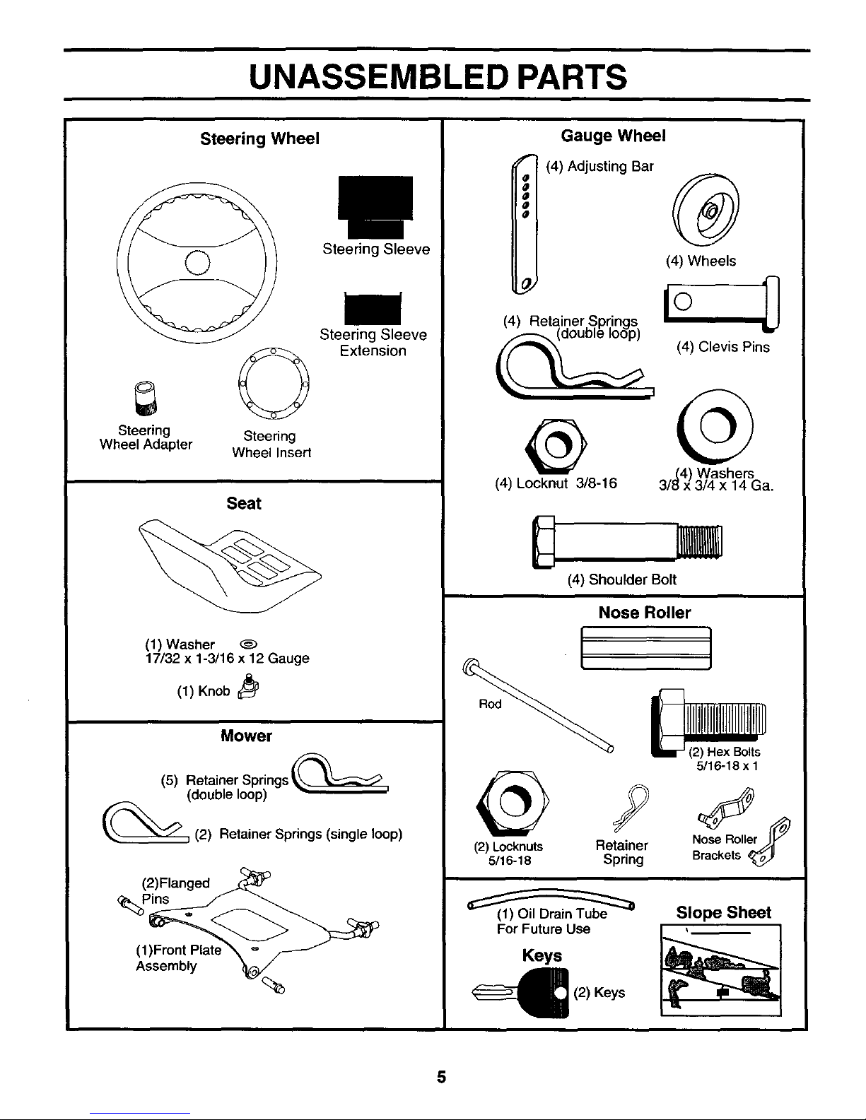
UNASSEMBLED PARTS
Steering Wheel
Steering Steering
Wheel Adapter Wheel Insert
Steering Sleeve
Steering Sleeve
Extension
Seat
(1) Washer
17/32 x 1-3/16 x 12 Gauge
(1) Knob
Mower
(5) Retainer Springs _
(double loop)
_(2) Retainer Springs (single loop)
(2)Flanged
_Pins
(1)Front Plat_
Assembly
%5
Gauge Wheel
f" (4) Adjusting Bar
o
o
o
o
o
,.,(4) Washers
/e x 3/4 x 14Ca.
(4) Locknut 3/8-16
®
(4) Wheels
(4) Clevis Pins
(4) Shoulder Bolt
Nose Roller
(2) Locknuts Retainer
5/16-18 Spring
For Future Use
Keys
(2) Keys
Slope Sheet
5
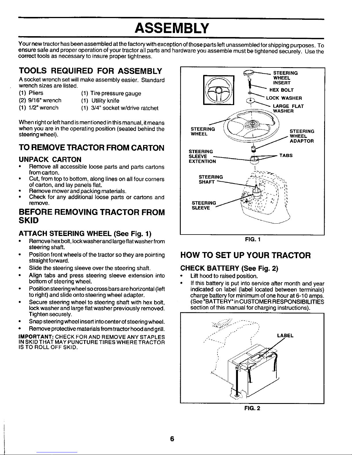
ASSEMBLY
Your newtractor has been assembled at the factory withexception ofthose parts leftunassembled forshipping purposes. To
ensure safe and proper operation of your tractor all parts and hardware you assemble must be tightened securely. Use the
correct tools as necessary to insure proper tightness.
TOOLS REQUIRED FOR ASSEMBLY
A socket wrench set will make assembly easier. Standard
wrench sizes are listed.
(1) Pliers (1) Tire pressure gauge
(2) 9/16" wrench (1) Utility knife
(1) 1/2" wrench (1) 3/4" socket w/drive ratchet
When right or left hand is mentioned in this manual, itmeans
when you are in the operating position (seated behind the
steedng wheel).
TO REMOVE TRACTOR FROM CARTON
UNPACK CARTON
• Remove all accessible loose parts and parts cartons
from carton.
• Cut, from top to bottom, along lines on all four corners
of carton, and lay panels flat.
• Remove mower and packing materials.
• Check for any additional loose parts or cartons and
remove.
BEFORE REMOVING TRACTOR FROM
SKID
STEERING
_ WHEEL
_....,.,.. INSERT
_- HEX BOLT
: _ LOCK WASHER
I(_ LARGE FLAT
ASHER
STEERING _ \ _" _-_J_ // STEERING
WHEEL \."_-_ J L _,,-"_JJ WHEEL
STEERING _ ADAPTOR
SLEEVE _ TABS
EXTENTION
ALL-_- --_-,
STEERING ,- - _-: -- - t\\_
SHAFT """-"',.,.--- ' | ,,_-_-'---__ "_,,
STEERING , , / ',,
SLEEVE _ _,_' ',_." /
ATrACH STEERING WHEEL (See Fig. 1)
• Remove hexbolt,lockwasher and largeflatwasher frem
steering shaft.
• Position frontwheels of the tractor so they are pointing
straightforward.
• Slide the steering sleeve over the steedng shaft.
• Align tabs and press steering sleeve extension into
bottom of steering wheel.
• Positionsteering wheel socrossbars are horizontal(left
to right) and slide onto steering wheel adapter.
• Secure steering wheel to steering shaft with hex bolt,
lock washer and large flat washer previously removed.
Tighten securely.
• Snap steeringwheelinsert int°center°t steering wheel"
• Remove protectivematerials fromtractor hoodand grill.
IMPORTANT: CHECK FOR AND REMOVE ANY STAPLES
IN SKID THAT MAY PUNCTURE TIRES WHERE TRACTOR
IS TO ROLL OFF SKID,
FIG. 1
HOW TO SET UP YOUR TRACTOR
CHECK BATTERY (See Fig. 2)
• Lifthood to raised position.
• If this battery is put into service after month and year
indicated on label (label located between terminals)
charge battery for minimum of one hour at 6-10 amps.
(See "BATTERY" inCUSTOMER RESPONSIBILITIES
section of this manual forcharging instructions).
-' LABEL
i
.?
FIG. 2
6
ASSEMBLY
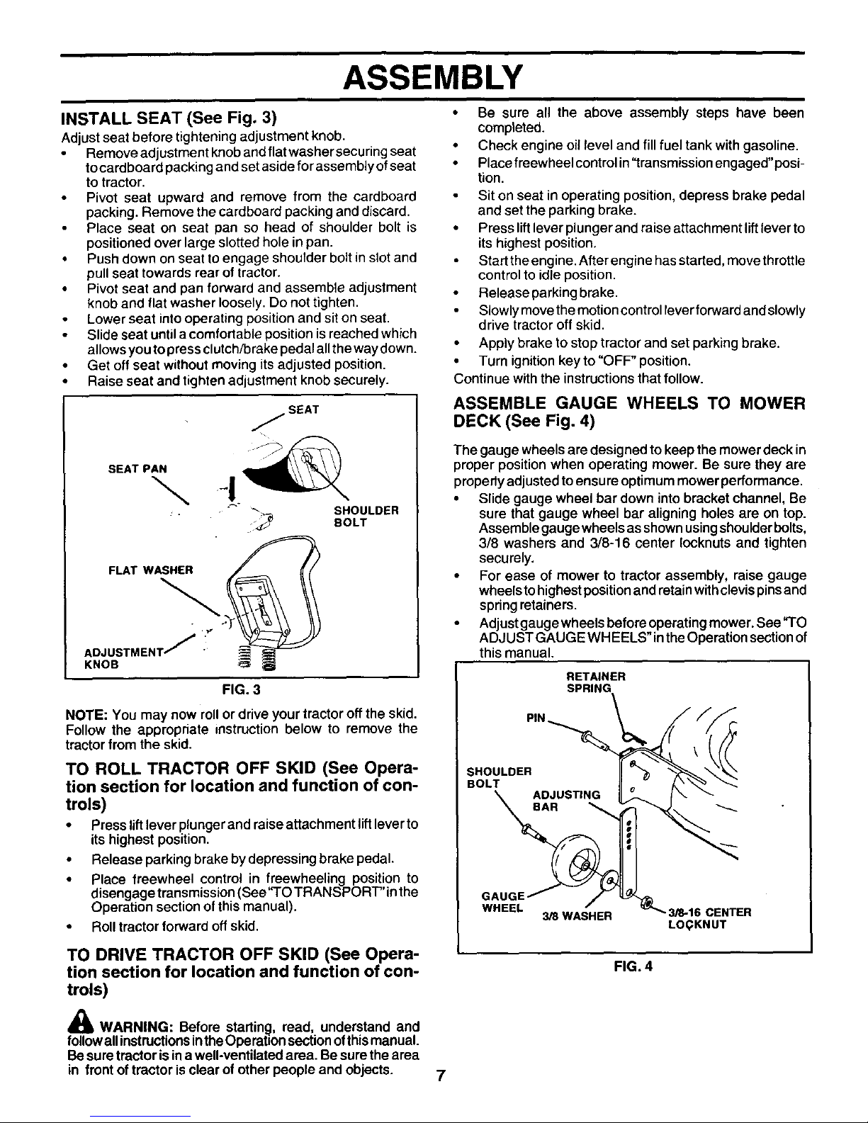
INSTALL SEAT (See Fig. 3)
Adjust seat before tightening adjustment knob.
Remove adjustment knob and flat washer securing seat
tocardboard packing and set aside for assembly of seat
to tractor.
Pivot seat upward and remove from the cardboard
packing. Remove the cardboard packing and discard.
Place seat on seat pan so head of shoulder bolt is
positioned over large slotted hole inpan.
• Push down on seat to engage shoulder bolt in slot and
pull seat towards rear of tractor.
• Pivot seat and pan forward and assemble adjustment
knob and flat washer loosely. Do not tighten.
Lower seat into operating position and sit on seat.
Slide seat until a comfortable position is reached which
allows you to press clutch/brake pedal all the way down.
• Get off seat without moving its adjusted position.
• Raise seat and tighten adjustment knob securely.
SEAT
SEAT PAN
FLAT WASHER
AOJUST.ENT/!
KNOB
SHOULDER
BOLT
FIG. 3
NOTE: You may now roll or drive your tractor off the skid.
Follow the appropriate instruction below to remove the
tractor from the skid.
TO ROLL TRACTOR OFF SKID (See Opera-
tion section for location and function of con-
trols)
• Press liftlever plunger and raise attachment lift leverto
its highest position.
• Release parking brake by depressing brake pedal.
• Place freewheel control in freewheeling position to
disengage transmission (See"TO TRANSPORT"in the
Operation section of this manual).
• Roll tractor forward off skid.
TO DRIVE TRACTOR OFF SKID (See Opera-
tion section for location and function of con-
trols)
WARNING: Before startin_h read, understand and
follow all instructionsintheOperation sectionof thismanual.
Besure tractor is in awell-ventilated area. Be sure the area
in front of tractor isclear ofother people and objects.
• Be sure all the above assembly steps have been
completed.
• Check engine oil level and fill fuel tank with gasoline•
• Place freewheel control in "transmission engaged"posi-
tion.
Sit on seat in operating position, depress brake pedal
and set the parking brake•
• Press lift lever plunger and raise attachment lift lever to
its highest position.
Start the engine. After engine has started, move throttle
control to idle position.
Release parking brake.
Slowly move the motion control leverforward and slowly
drive tractor off skid.
• Apply brake to stop tractor and set parking brake.
• Turn ignition key to "OFF" position.
Continue with the instructions that follow.
ASSEMBLE GAUGE WHEELS TO MOWER
DECK (See Fig. 4)
The gauge wheels are designed to keep the mower deck in
proper position when operating mower. Be sure they are
properly adjusted to ensu re optimum mower performance.
• Slide gauge wheel bar down into bracket channel, Be
sure that gauge wheel bar aligning holes are on top.
Assemble gauge wheels as shown using shoulder bolts,
3/8 washers and 3/8-16 center Iocknuts and tighten
securely.
• For ease of mower to tractor assembly, raise gauge
wheels to highest position and retain with clevis pins and
spring retainers.
• Adjust gauge wheels before operating mower. See"TO
ADJUST GAUGE WH EELS" inthe Operation section of
this manual.
RETAINER
SPI_
PIN
SHOULDER
BOLT
ADJUSTING
BAR
GAUGE,
WHEEL
3/8WASHER
3/8-16 CENTER
LOQKNUT
FIG. 4
7
ASSEMBLY
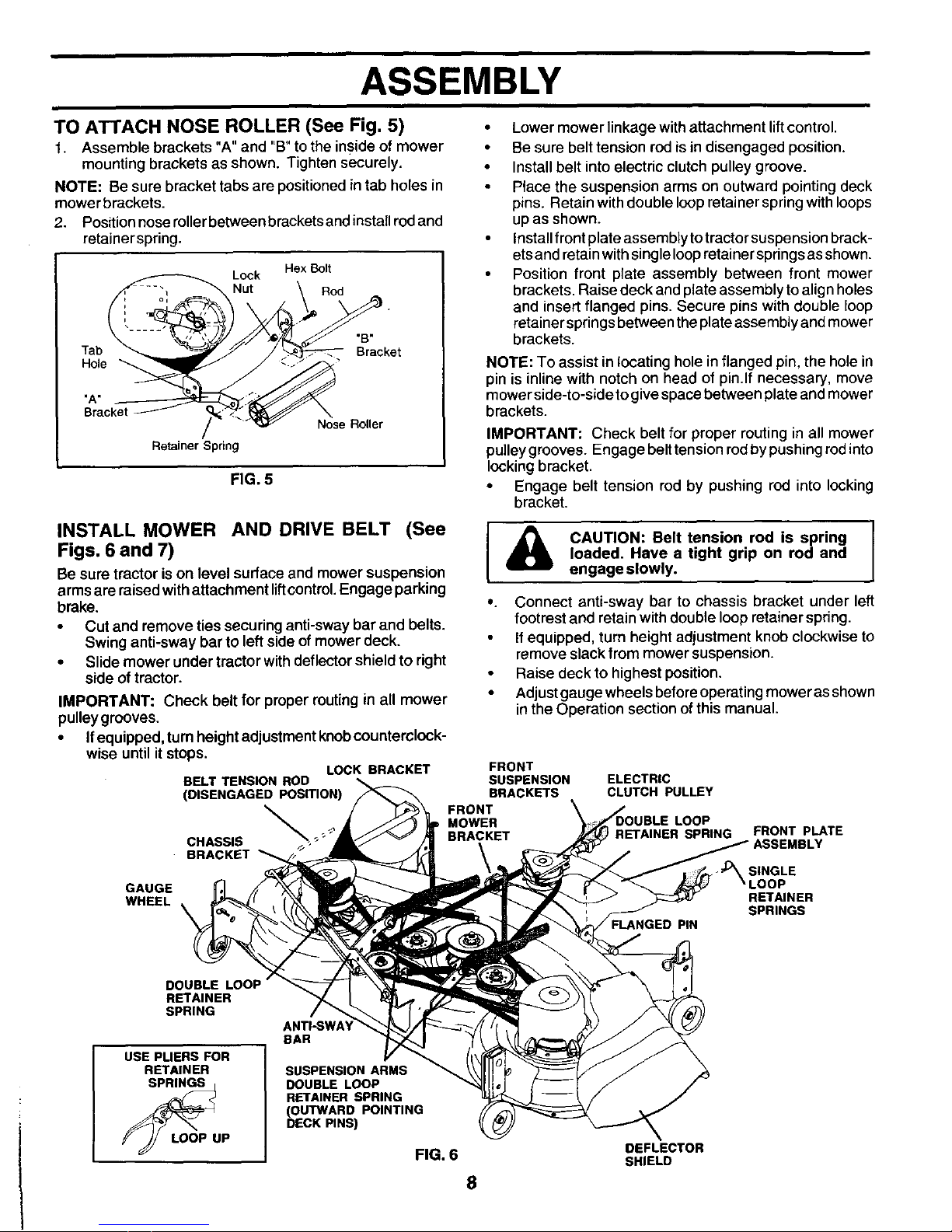
TO ATTACH NOSE ROLLER (See Fig. 5)
1. Assemble brackets "A"and "B" tothe inside of mower
mounting brackets as shown. Tighten securely.
NOTE: Be sure bracket tabs are positionedintab holes in
mower brackets.
2. Positionnoseroller between bracketsand installrodand
retainer spring.
Hex Bolt
Lock
Nut Rod
Tab
Hole
"B"
Bracket
"A"
Bracket
Retainer Spring
Nose Roller
FIG. 5
INSTALL MOWER AND DRIVE BELT (See
Figs. 6 and 7)
Be sure tractor ison level surface and mower suspension
armsare raised withattachment liftcontrol.Engage parking
brake.
• Cut and remove ties securing anti-sway bar and belts.
Swing anti-sway bar to left side of mower deck.
• Slide mower under tractor with deflectorshield to right
side of tractor.
IMPORTANT: Check belt for proper routing in all mower
pulley grooves.
• If equipped, turn height adjustment knobcounterclock-
wise until it stops.
LOCK BRACKET
BELT TENSION ROD
(DISENGAGED POSITION)
CHASSIS _- _'_"
5"
BRACKET
GAUGE
WHEEL
• Lower mower linkage withattachment lift control.
• Be sure belt tension rod is in disengaged position.
• Install belt intoelectric clutch pulley groove.
• Place the suspension arms on outward pointing deck
pins. Retain with double loop retainer spring with loops
upas shown.
Installfront plate assembly totractor suspension brack-
etsand retainwithsingle loopretainersprings as shown.
• Position front plate assembly between front mower
brackets. Raise deck and plate assembly toalign holes
and insert flanged pins. Secure pins with double loop
retainer springs between theplate assembly and mower
brackets.
NOTE: To assist in locating hole in flanged pin, the hole in
pin is inline with notch on head of pin.If necessary, move
mower side-to-side to give space between plate and mower
brackets.
IMPORTANT: Check belt for proper routing in all mower
pulleygrooves. Engage belt tension rodby pushing rod into
lockingbracket.
• Engage belt tension rod by pushing rod into locking
bracket.
I & CAUTION: Belt tension rod is spring [
loaded. Have a tight grip on rodand
engage slowly.
°. Connect anti-sway bar to chassis bracket under left
footrest and retain with double loop retainer spring.
If equipped, turn height adjustment knob clockwise to
remove slack from mower suspension.
• Raise deck to highest position.
• Adjust gauge wheels before operating mower as shown
in the Operation section of this manual.
FRONT
SUSPENSION ELECTRIC
BRACKETS CLUTCH PULLEY
FRONT
MOWER LOOP
BRACKET I RETAINER SPRING
PIN
FRONT pLATE
ASSEMBLY
SINGLE
RETAINER
SPRINGS
DOUBLE LOOP
RETAINER
SPRING
USE PLIERS FOR
RETAINER
K J/ LOOP UP
ANTI-SWA'_
BAR
SUSPENSION ARMS
DOUBLE LOOP
RETAINER SPRING
(OUTWARD POINTING
DECK PINS)
FIG. 6
8
DEFLECTOR
SHIELD
ASSEMBLY
CHECK TIRE PRESSURE
The tires onyour tractor were overinflated at the factory for
shipping purposes. Correct tire pressure is important for
best cutting performance.
• Reduce tire pressure to PSI shown in "PRODUCT
SPECIFICATIONS" section of this manual.
CHECK MOWER LEVELNESS
For best cutting results, mower should be properly leveled.
See "TO LEVEL MOWER HOUSING" in the Service and
Adjustments section of this manual.
CHECK FOR PROPER POSITION OF ALL
BELTS
See the figures that are shown for replacing motion, mower
drive, and mower blade drive belts in the Service and
Adjustments section of this manual. Verify that the belts are
routed correctly.
,/CHECKL IS T
BEFORE YOU OPERA TEAND ENJOY YOUR NEW TRAC-
TOR, WE WISH TO ASSURE THAT YOU RECEIVE THE
BEST PERFORMANCEAND SA TISFAC TION FROM THIS
QUALITY PRODUC T_
PLEASE REVIEW THE FOLLOWING CHECKLIST"
,/ All assembly instructions have been completed.
,/ No remaining loose parts in carton.
,/ Batteryis properly prepared and charged. (Minimum 1
hour at 6 amps).
•/ Seat is adjusted comfortably and tightened securely.
,/ All tires are properly inflated. (For shipping purposes,
the tires were ovednflated at the factory).
•/ Be sure mower deck is properly leveled side-to-side/
front-to-rear for best cutting results. (Tires must be
properly inflated for leveling).
,/ Check mower and drive belts. Be sure they are routed
properly around pulleys and inside all belt keepers.
•/ Check wiring. See that all connections are still secure
and wires are properly clamped.
,/ Before driving tractor, be sure freewheel control is in
drive position.
WHILE LEARNING HOW TO USE YOUR TRACTOR, PAY
EXTRA A TTENTION TO THE FOLLOWING IMPORTANT
ITEMS:
,/ Engine oil is at proper level.
,/ Fuel tank is filled with fresh, clean, regular unleaded
gasoline.
,/ Become familiar with all controls - their location and
function. Operate them before you start the engine.
,/ Be sure brake system is in safe operating condition.
,/" Itisimportant topurgethe transmission before operating
your tractor for the first time. Follow proper starting and
transmission purging instructions (See "TO START
ENGINE" and "PURGETRANSMISSION" in Operation
section of this manual).
9
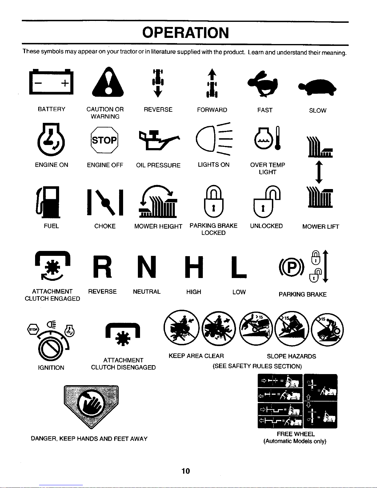
OPERATION
These symbols may appear on your tractor or in literature suppled withthe product. Learn and understand their meaning.
f :l A ,=
BATTERY CAUTION OR REVERSE FORWARD FAST SLOW
WARNING
ENG,NEONENG,NEOFFO,LPRESSOREL,GHTSONOVI,_=P I
FUEL CHOKE MOWER HEIGHT PARKING BRAKE UNLOCKED MOWER LIFT
LOCKED
R
ATFACHMENT REVERSE
CLUTCH ENGAGED
N H L (®>SI
NEUTRAL HIGH LOW
IGNITION
ATTACHMENT
CLUTCH DISENGAGED
PARKING BRAKE
KEEP AREA CLEAR SLOPE HAZARDS
(SEE SAFETYRULES SECTION)
DANGER, KEEP HANDS AND FEET AWAY
10
FREE WHEEL
(AutomaticModels only)
OPERATION
KNOW YOUR TRACTOR
READ THIS OWNER'S MANUAL AND SAFETY RULES BEFORE OPERATING YOUR TRACTOR.
Compare the illustrations withyour tractorto familiarize yourselfwith the location ofvarious controlsand adjustments. Save
thismanual for future reference.
IGNITION
SWITCH LIGHT SWITCH
AMMETER POSITION
THROTTLE
CONTF
BRAKE PEDAL
CHOKE
CONTROL ATTACHMENT
CLUTCH SWITCH
LIFT LEVER
PLUNGER
MOTION DRIVE
BELT TENSION
HANDLE
LEVER
PARKING
BRAKE LEVER
FREEWHEEL
CONTROL
HEIGHT
ADJUSTMENT
KNOB
MOTION
CONTROL
LEVER
FIG. 7
Our tractors conform to the safety standards of the American National Standards Institute.
ATTACHMENT CLUTCH SWITCH -Used to engage mower
blades or other attachments mounted to your tractor.
LIFTLEVER- Used toraise and lower mower deckorother
attachments mounted toyour tractor.
BRAKE PEDAL - Used for brakingthe tractor and starting
theengine.
MOTION CONTROL LEVER - Selects the speed and
direction of tractor.
CHOKE CONTROL - Used when startingacold engine.
LIGHT SWITCH - Turns the headlights on and off.
LIFT LEVER PLUNGER - Used to release attachment lift
lever when changing itsposition.
11
THROTTLE CONTROL - Used to control engine speed.
FREEWHEEL CONTROL - Disengages transmission for
pushing or slowly towing the tractor with the engine off.
IGNITION SWITCH - Used to start a_d stop the engine.
AMMETER- Indicates battery charging(+) ordischarging(-).
PARKING BRAKE LEVER - Locks brake pedal into the
brake position.
HEIGHT ADJUSTMENT KNOB - Used to adjustthe mower
height.
MOTION DRIVE BELT TENSION HANDLE- Used when
changing motionddve beltand, if necessary, startingengine
under extremely cold conditions.
OPERATION
I
The operation of any tractor can result in foreign objects thrown into the eyes, which can
result in severe eye damage. Always wear safety glasses or eye shields while operating
your tractor or performing any adjustments or repairs. We recommend a wide vision
safety mask over spectacles or standard safety glasses.
HOW TO USE YOUR TRACTOR
TO SET PARKING BRAKE (See Fig. 8)
Your tractor isequipped withan operator presence sensing
switch. When engine is running, any attempt bythe operator
to leave the seat without first setting the parking brake will
shut off the engine.
• Depress brake pedal into full "BRAKE" position and
hold.
I
NOTE: Under certain conditions whentractor isstanding idle
with the engine running, hot engine exhaust gases may
cause "browning" of grass. To eliminate this possibility,
always stop engine when stopping tractor on grass areas.
&
CAUTION: Always stop tractor com- I
pletely, as described above, before leav-
I
ing the operator's position; to empty
grass catcher, etc.
Place parking brake lever in "ENGAGED" position and
release pressure from brake pedal. Pedal should
remain in "BRAKE" position. Make sure parking brake
will hold tractor secure.
PUSH IN TO ATTACHMENT
CHOKE "DISENGAGE" CLUTCH SWITCH
CONTROL \ PULL OUTTO
THROTTLE \ \ ENGAGE
CONTROL _3_ \ ,
-. LEVER
"DRIVE"_/-'" _/_ _PARKING BRAKE
POSITION _ _/ i _ "ENGAGED"
_'_ _ _.r,z,_ _'_ . POSITION
HEIGHT / "DISENGAGED"
ADJUSTMENT POSITION
KNOB
FIG. 8
MOWER BLADES -
• To stop mower blades,move attachment clutch switch
to "DISENGAGED" position.
GROUND DRIVE-
• To stop ground drive, depress brake pedal into full
"BRAKE" position.
IMPORTANT: THE MOTION CONTROL LEVER
RETURNS TO NEUTRAL (N) POSITION WHEN THE
BRAKE PEDAL IS FULLY DEPRESSED.
ENGINE -
• Move throttle control to slow position.
NOTE: Failure to move throttle control to slow position and
allowing engine to idle before stopping may cause engine
to "backfire".
• Turn ignition key to "OFF" position and remove key,
Always remove key when leaving tractor to prevent
unauthorized use.
• Never use choke to stop engine.
IMPORTANT: LEAVING THE IGNITION SWITCH IN ANY
POSITION OTHER THAN "OFF" WILL CAUSE THE
BATTERY TO BE DISCHARGED, (DEAD).
12
TO USE THRO'n'LE CONTROL (See Fig. 8)
Always operate engine at full throttle.
• Operating engine at less than full throttle reduces the
battery charging rate.
• Full throttle offers the best mower performance.
TO USE CHOKE CONTROL (See Fig. 8)
Usechoke controlwhenever you are startinga cold engine,
Do not use to start a warm engine.
• knob in to disengage.
TO MOVE FORWARD AND BACKWARD
(See Fig. 8)
CAUTION: Do not attempt to operate
motion control lever when the parking
brake is set or when the brake pedal is
depressed. Doing so may result in
misadjustment to the drive control sys-
tem.
The direction and speed of movement iscontrolled by the
motioncontrol lever.
• Start tractor with motion control lever in neutral (N)
position.
• Release parking brake.
Slowly move motion control lever to desired position.
TO ADJUST MOWER CUTTING HEIGHT
(See Rg. 8)
The cutting height iscontrolled bytuming the height adjust-
ment knob in desired direction.
• Turn knob clockwise (F_) to raisecutting height.
• Turn knob counterclockwise (P_) to lower cutting
height.
The cutting height range is approximately 1-1/2" to 4-1/2".
The heights are measured from theground to the blade tip
withthe engine notrunning. These heightsare approximate
and may vary depending upon soil conditions, height of
grass and types ofgrass being mowed.
• The average lawnshould be cut toapproximately 2-1/2
inches during the cool season and to over 3 inches
during hot months. For healthier and better looking
lawns, mow often and after moderate growth.
• For best cutting performance, grass over 6 inches in
height should be mowed twice. Make the first cut
relatively high; the second to desired height.
OPERATION
TO OPERATE ON HILLS
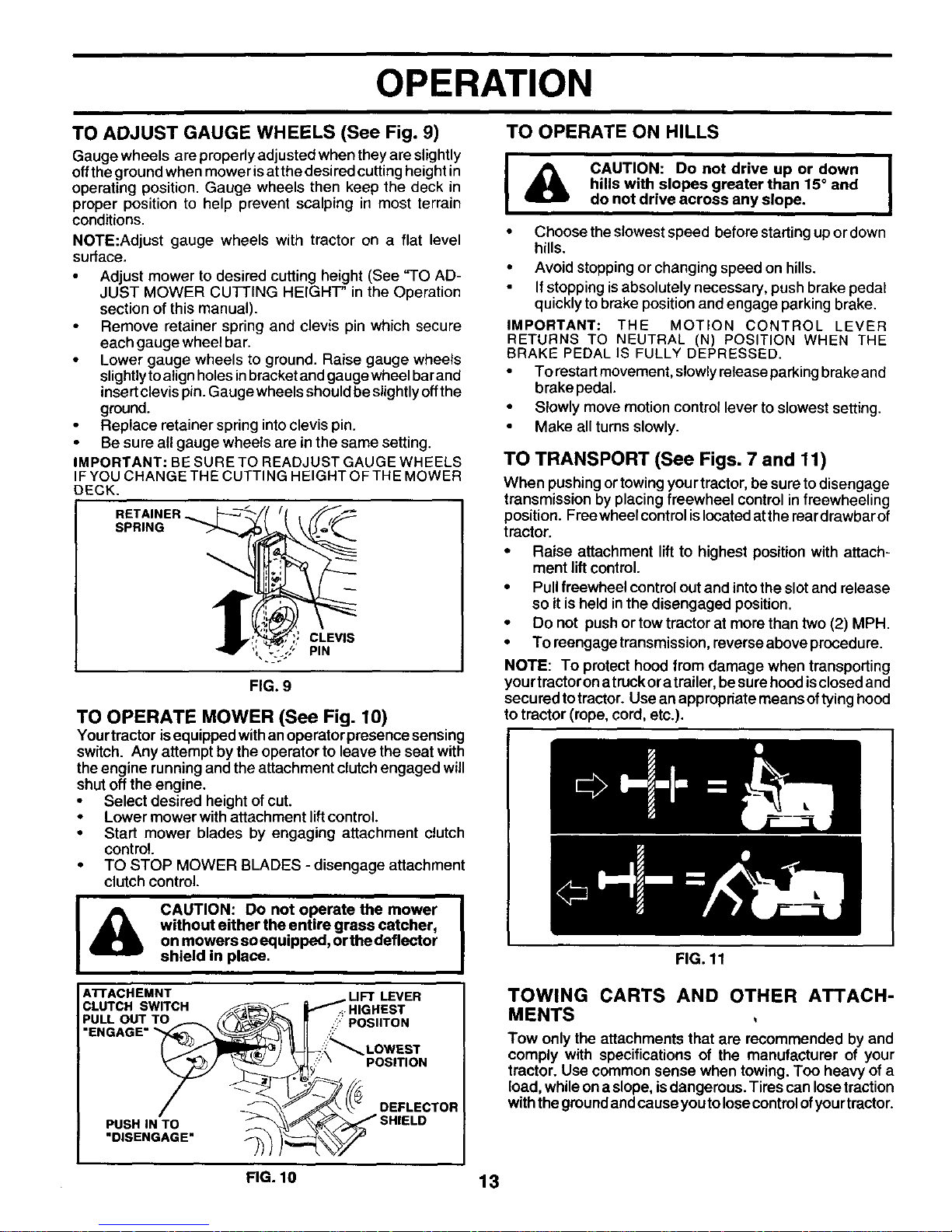
TO ADJUST GAUGE WHEELS (See Fig. 9)
Gauge wheels are properly adjusted when they are slightly
offthe ground when mower is at the desired cutting height in
operating position. Gauge wheels then keep the deck in
proper position to help prevent scalping in most terrain
conditions.
NOTE:Adjust gauge wheels with tractor on a flat level
sudace,
• Adjust mower to desired cutting height (See "TO AD-
JUST MOWER CUTTING HEIGHT" in the Operation
section of this manual).
• Remove retainer spring and clevis pin which secure
each gauge wheel bar.
• Lower gauge wheels to ground. Raise gauge wheels
slightly toalign holes inbracket and gauge wheel bar and
insertclevis pin. Gauge wheels should be slightly off the
ground.
Replace retainer spring into clevis pin.
• Be sure all gauge wheels are in the same setting.
IMPORTANT: BE SURE TO READJUST GAUGE WHEELS
IF YOU CHANGETHE CUTTING HEIGHTOFTHE MOWER
DECK.
RETAINER
SPRING
CLEVIS
PIN
FIG. 9
TO OPERATE MOWER (See Fig. 10)
Yourtractor isequipped withan operator presence sensing
switch. Any attempt by the operator to leave the seat with
theengine runningand the attachment clutchengaged will
shutoff the engine.
• Select desired height of cut.
• Lower mower with attachment liftcontrol.
• Start mower blades by engaging attachment clutch
control.
• TO STOP MOWER BLADES- disengage attachment
clutch control.
CAUTION: Do not operate the mower
without either the entire grass catcher,
on mowers soequipped, orthe deflector
shield in place.
ATrACHEMNT
CLUTCH SWITCH
u&o#z'To
PUSH IN TO •
DISENGAGE
f _UFT LEVER
.._HIGHEST
r,_: r` POSIITON
_:_ LOWEST
_;::' POSITION
i
I _ CAUTION: Do not drive up or down
411
hills with slopes greater than 15° and
do not drive across any slope.
• Choose the slowest speed before starting up or down
hills.
• Avoid stopping or changing speed on hills.
If stopping is absolutely necessary, push brake pedal
quickly to brake position and engage parking brake.
IMPORTANT: THE MOTION CONTROL LEVER
RETURNS TO NEUTRAL (N) POSITION WHEN THE
BRAKE PEDAL IS FULLY DEPRESSED.
• To restart movement, slowly release parking brake and
brake pedal.
• Slowly move motion control lever to slowest setting.
Make all turns slowly.
TO TRANSPORT (See Figs. 7 and 11)
When pushing ortowing yourtractor, be sure to disengage
transmission by placing freewheel control in freewheeling
position. Freewheel controlis locatedatthe reardrawbarof
tractor.
• Raise attachment lift to highest position with attach-
ment lift control.
• Pull freewhee! control out and intothe slotand release
so it is held inthe disengaged position,
• Do not push or tow tractor at more than two (2) MPH.
• To reengage transmission,reverse aboveprocedure.
NOTE: To protect hood from damage when transporting
yourtractoron atruckor atrailer, besure hood isclosedand
secured to tractor. Use an appropriate means oftying hood
to tractor (rope, cord, etc.).
FIG. 11
TOWING CARTS AND OTHER ATTACH-
MENTS
Tow only the attachments that are recommended by and
comply with specifications of the manufacturer of your
tractor. Usa common sense when towing. Too heavy of a
load, while ona slope, is dangerous. Tires can losetraction
withthe groundandcause you tolosecontrolofyourtractor.
FIG. 10 13
OPERATION
BEFORE STARTING THE ENGINE
CHECK ENGINE OIL LEVEL
• The engine in your tractor has been shipped, from the
factory, already filledwith summer weight oil.
Check engine oilwith tractor on level ground.
Remove oil fillcap/dipstick and wipe clean, reinsert the
dipstick and screw cap tight, wait for a few seconds,
remove and read oil level. If necessary, add oil until
"FULL" mark on dipstick isreached. Do not overfill.
• For cold weather operation you should change oil for
easier starting (See "OIL VISCOSITY CHART" in the
Customer Responsibilities section of this manual).
• To change engine oil, see the Customer Responsibili-
ties section in this manual.
ADD GASOLINE
• Fill fuel tank. Use fresh, clean, regular unleaded
gasoline with a minimum of87 octane. (Use of leaded
gasoline will increase carbon and lead oxide deposits
and reduce valve life). Do not mix oil with gasoline.
Purchase fuel in quantities that can be used within 30
days to assure fuel freshness.
IMPORTANT; WHEN OPERATING IN TEMPERATURES
BELOW 32°F(0°C), USE FRESH, CLEAN WINTER GRADE
GASOLINE TO HELP INSURE GOOD COLD WEATHER
STARTING.
WARNING: Experience indicates that alcohol blended fuels
(called gasohol or using ethanol or methanol) can attract
moisture which leads to separation and formation of acids
dudng storage. Acidic gas can damage the fuel system of
an engine while in storage. To avoid engine problems, the
fuel system should be emptied before storage of30 days or
longer. Drain the gastank, start theengine and let itrununtil
the fuel lines and carburetor are empty. Use fresh fuel next
season. See Storage Instructionsfor additional information.
Never use engine or carburetor cleaner products inthe fuel
tank orpermanent damage may occur.
|
CAUTION: Fill to bottom of gas tank I
filler neck. Do not overfill. Wipe off any
I
spilled oil or fuel. Do not store, spill or
use gasoline near an open flame.
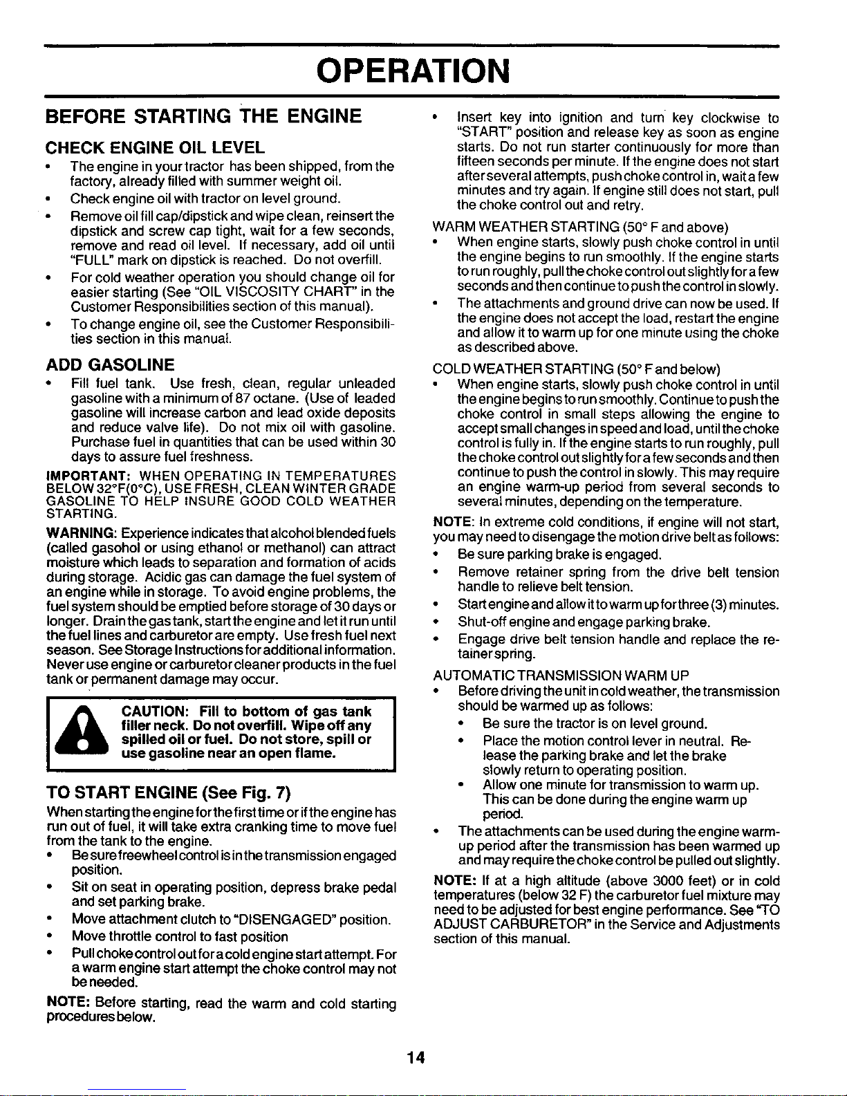
TO START ENGINE (See Fig. 7)
When startingthe engine forthe first time orifthe engine has
run out of fuel, it willtake extra cranking time to move fuel
from the tank to the engine.
• Be surefreewheel controlisinthe transmissionengaged
position.
• Sit on seat in operating position,depress brake pedal
and set parking brake.
• Move attachment clutch to "DISENGAGED" position.
• Move throttle control to fast position
• Pullchoke controloutfora coldengine startattempt. For
a warm engine start attempt the choke control may not
beneeded.
NOTE: Before starting, read the warm and cold starting
procedures below.
Insert key into ignition and turn key clockwise to
"START" position and release key as soon as engine
starts. Do not run starter continuously for more than
fifteen seconds per minute. If the engine does not start
after several attempts, push choke control in, wait afew
minutes and try again. If engine still does not start, pull
the choke control out and retry.
WARM WEATHER STARTING (50° F and above)
When engine starts, slowly push choke control in until
the engine begins to run smoothly. If the engine starts
to run roughly, pull the choke control out slightly fora few
seconds and then continue to push the control in slowly.
The attachments and ground drive can now be used. If
the engine does not accept the load, restart the engine
and allow itto warm up for one minute using the choke
as described above.
COLD WEATHER STARTING (50° Fand below)
When engine starts, slowly push choke control in until
the engine begins to run smoothly. Continue to push the
choke control in small steps allowing the engine to
accept small changes in speed and load, until the choke
control is fully in. If the engine starts to run roughly, pull
the choke control out slightly for afew seconds and then
continue to push the control in slowly. This may require
an engine warm-up period from several seconds to
several minutes, depending on the temperature.
NOTE: In extreme cold conditions, if engine will not start,
you may need todisengage the motion drive belt as follows:
• Be sure parking brake is engaged.
• Remove retainer spring from the drive belt tension
handle to relieve belt tension.
• Start engineand altowit towarm upfor three (3) minutes.
• Shut-off engine and engage parking brake.
• Engage drive belt tension handle and replace the re-
tainerspdng.
AUTOMATIC TRANSMISSION WARM UP
• Before driving the unit in cold weather, the transmission
should be warmed up as follows:
• Be sure the tractor is on level ground.
• Place the motion control lever in neutral. Re-
lease the parking brake and let the brake
slowly return to operating position.
• Allow one minute for transmission to warm up.
This can be done during the engine warm up
pedod.
• The attachments can be used during the engine warm-
up period after the transmission has been warmed up
and may require the choke control be pulled out slightly.
NOTE: If at a high altitude (above 3000 feet) or in cold
temperatures (below 32 F)the carburetor fuel mixture may
need to be adjusted for best engine performance. See %0
ADJUST CARBURETOR" in the Service and Adjustments
section of this manual.
14

OPERATION
PURGE TRANSMISSION
I _ CAUTION: Neverengageordisengage I
freewheel lever while the engine is
running.
To ensure proper operation and performance, it is recom-
mended that the transmission be purged before operating
tractor for the first time. This procedure will remove any
trapped air inside the transmission which may have devel-
oped during shipping of your tractor.
IMPORTANT: SHOULD YOUR TRANSMISSION
REQUIRE REMOVAL FOR SERVICE OR REPLACEMENT,
IT SHOULD BE PURGED AFTER REINSTALLATION
BEFORE OPERATING THE TRACTOR.
Place tractor safely on level surface with engine off and
parking brake set.
Disengage transmission by placing freewheel control in
freewheeling position (See 'q-o TRANSPORT" inthis
section of manual).
• Sitting in thetractor seat, start engine. After the engine
is running, move throttle control to slow position.
Disengage parking brake
• Move motion control lever to full forward position and
hold for five (5) seconds. Move lever to full reverse
position and hold for five (5) seconds. Repeat this
procedure three (3) times.
NOTE: During this procedure there will be no movement of
drive wheels. The air isbeing removed from hydraulic drive
system.
• Move motion control lever to neutral (N) position. Shut-
off engine and set parking brake.
• Engage transmission by placing freewheel control in
driving position (See "TO TRANSPORT" in this section
of manual).
• Sitting in the tractor seat, start engine. After the engine
is running, move throttle control to half (1/2) speed.
Disengage parking brake.
• Slowly move motion control lever forward, after the
tractor moves approximately five (5)feet, slowly move
motion control lever to reverse position. After the
tractor moves approximately five (5) feet return the
motion control levertothe neutral (N) position. Repeat
this procedure with the motion control lever three (3)
times.
• Your tractor is now purged and now ready for normal
operation.
MOWING TIPS
• Tire chains cannot be used when the mower housing is
attached to tractor.
• Mower should be properly leveled for best mowing
performance. See "TO LEVEL MOWER HOUSING" in
the Service and Adjustments section of this manual.
• The left hand side of mower should be used for trimming.
• Drive sothat clippings are discharged ontothe areathat
has been cut. Have the cut areato the right of the tractor.
This will result in a more even distribution of clippings
and more uniform cutting.
• When mowing large areas, start byturning tothe right so
thatclippings will discharge away from shrubs, fences,
driveways, etc. After one or two rounds, mow in the
opposite direction making left hand turns until finished
(See Fig. 12).
• If grass is extremely tall, it should be mowed twice to
reduce load and possible fire hazard from dried clip-
pings. Make first cut relatively high; the second to the
desired height.
• Do not mow grass when it is wet. Wet grass will plug
mower and leave undesirableclumps. Ailowgrasstodry
before mowing.
• Always operate engine at full throttle when mowing
to assure better mowing performance and proper dis-
charge of material. Regulate ground speed by selecting
a low enough gear to give the mower cutting perfor-
mance as well as the quality of cut desired.
When operating attachments, select a ground speed
that will suit the terrain and give best performance of the
attachment being used.
FIG. 12
15
CUSTOMER RESPONSIBILITIES
FILL IN DATES
ASYOUCOMPLETE
REGULARSERVICE f__ _'_d/_ ERVICE DATES
Check Brake Operation _ _V'
Check Tire Pressure
Check Operator Presence and
m Interlock Systems _V'
Check for Loose Fasteners V's V _
A Sharpen/Replace Mower Blades i3
Lubrication Chart
m Check Battery Level
R Clean Battery and Terminals
Check Transaide Cooling
Check V-Belts
Check Engine Oil Level V'
Change Engine Oil (with oil filter) Vtl,2 If
E Change Engine Oil (wrthout °ilfilter)cleanAir Filter _i 2
v'
G Clean Air Screen
Inspect Muffler/Spark Arrester If
N Replace Oil Filter (If equipped) _,2
Clean Engine Cooling Fins _ 2
Replace Spark Plug V' I_'
Replace Air Filter Paper Cartridge V'2
Replace Fuel Filter !_
1 - Change more often when operating under a heavy load or 3 - Replace blades more often when mowing in sandy soil.
in high ambient temperatures. 4 - Not _uired if equipped with maintenance*tree battery,
2 - Service more often when operating in didy or dusty conditions. 5 - 33ghten front axle pivot bolt to 35 ft.-Ibs, maximum.
DO not overtighten.
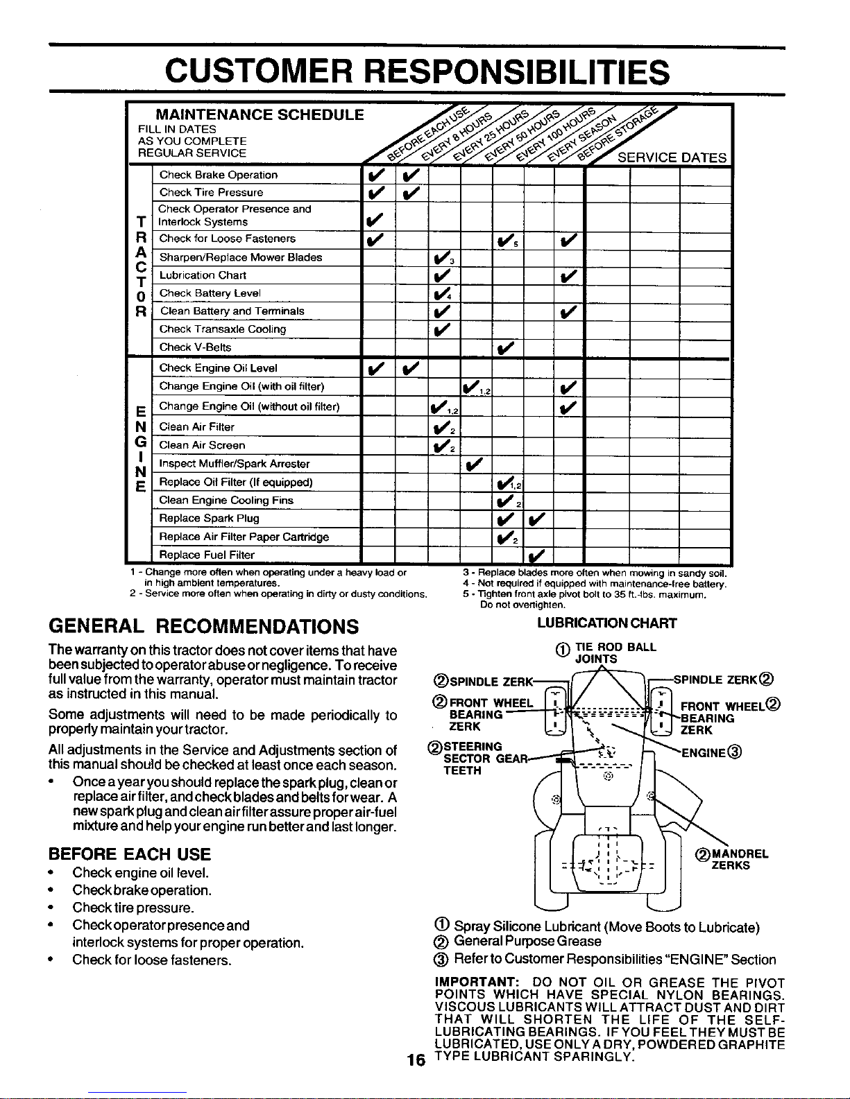
GENERAL RECOMMENDATIONS LUBRICATIONCHART
The warranty on thistractor does not cover items that have
been subjectedtooperator abuse ornegligence. To receive
fullvalue from the warranty, operator must maintain tractor
as instructed in this manual.
Some adjustments will need to be made periodically to
properly maintain your tractor.
All adjustments in the Service and Adjustments section of
this manual should be checked at least once each season.
• Once a year you should replace the spark plug, clean or
replace air fiRer,and check blades and belts for wear. A
new spark plug and clean air filterassure proper air-fuel
mixture and help your engine run better and last longer.
(_) TIE ROD BALL
JOINTS
ZERK_)
_)FRONT WHEEL FRONT WHEEL(_)
ZERK ZERK
TEETH
BEFORE EACH USE
• Check engine oil level.
• Check brake operation.
• Check tire pressure.
• Check operatorpresence and
interlocksystems for proper operation.
• Check for loose fasteners.
MANDREL
(_)ZERKS
16
(_) Spray Silicone Lubricant (Move Boots to Lubricate)
_) General PurposeGrease
(_) Refer to Customer Responsibilities "ENGINE" Section
IMPORTANT: DO NOT OIL OR GREASE THE PIVOT
POINTS WHICH HAVE SPECIAL NYLON BEARINGS.
VISCOUS LUBRICANTS WILL ATTRACT DUST AND DIRT
THAT WILL SHORTEN THE LIFE OF THE SELF-
LUBRICATING BEARINGS. IF YOU FEEL THEY MUST BE
LUBRICATED, USE ONLY A DRY, POWDERED GRAPHITE
TYPE LUBRICANT SPARINGLY.
 Loading...