

Poulan Pro POULANPRO 96192001902 Owner's Manual
IMPORTANT MANUAL Do Not Throw Away
OWNER'S MANUAL
MODEL NUMBER:
96192001902
SNOW THROWER
WARNING: ..................
Read the Owner's Manual and
follow all Warnings and Safety
Instructions. Failure to do so
can result in serious injury.
Always Wear Eye Protection During Operation
416804 09.20.07 SR
Printed in U.S.A.
III I
&
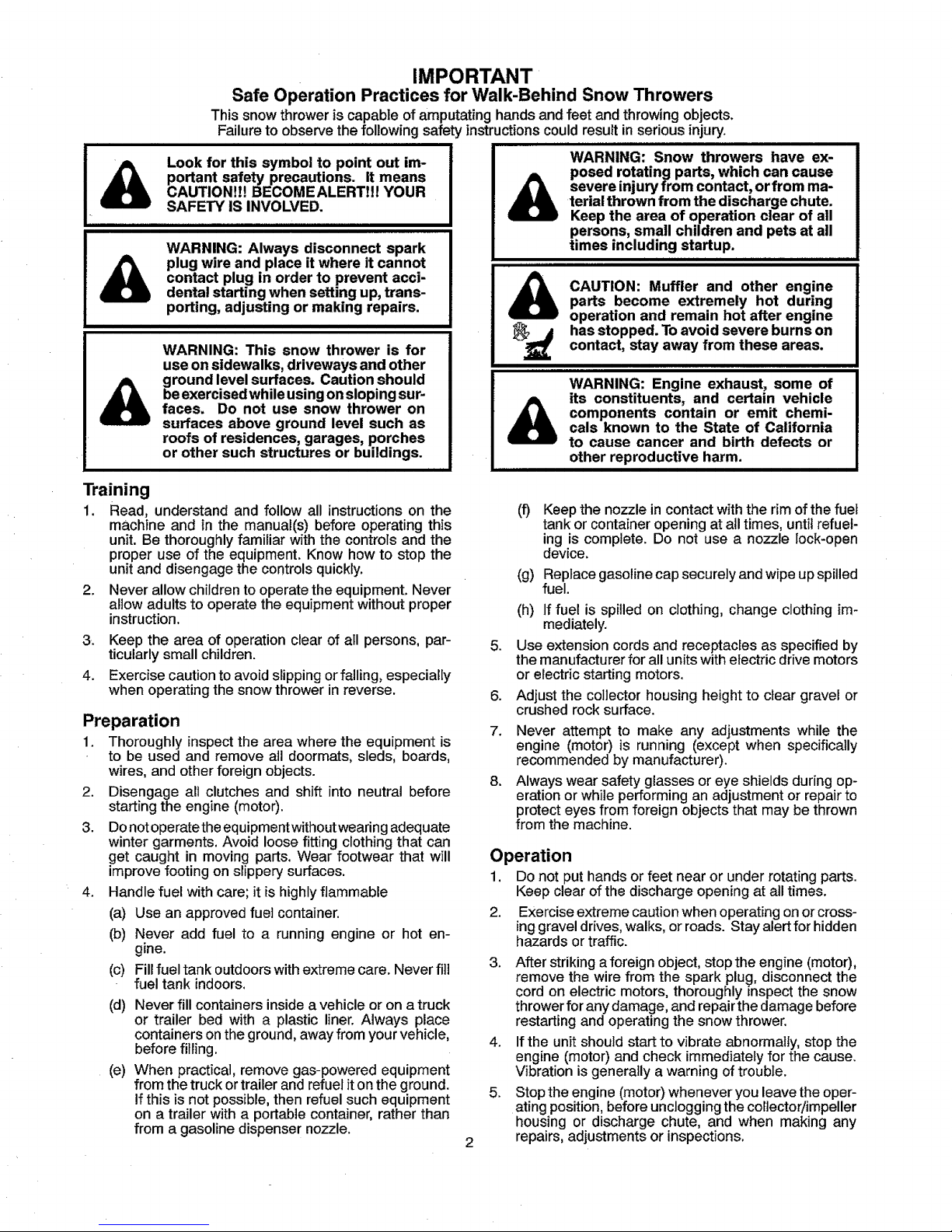
IMPORTANT
Safe Operation Practices for Walk-Behind Snow Throwers
This snow thrower is capable of amputating hands and feet and throwing objects.
Failure to observe the following safety instructions could result in serious injury.
i i llnll, iHll null ,I,l,,,m,,,,H n,ll
Look for this symbol to point out im-
portant safety precautions. It means
CAUTIONIH BECOMEALERT!H YOUR
SAFETY IS INVOLVED.
WARNING: Always disconnect spark
plug wire and place it where it cannot
contact plug in order to prevent acci-
dental starting when setting up, trans-
porting, adjusting or making repairs.
WARNING: This snow thrower is for
use on sidewalks, driveways and other
ground level surfaces. Caution should
be exercised while using on sloping sur-
faces. Do not use snow thrower on
surfaces above ground level such as
roofs of residences, garages, porches
or other such structures or buildings.
I I II
i i ii1,111i
&
WARNING: Snow throwers have ex-
posed rotating parts, which can cause
severe injury from contact, or from ma-
terial thrown from the discharge chute.
Keep the area of operation clear of all
persons, small children and pets at all
times including startup.
I I II I I I I II II IIII I II IIII I IIIIII III I II IIIIII II
CAUTION: Muffler and other engine
parts become extremely hot during
operation and remain hot after engine
has stopped. To avoid severe burns on
contact, stay away from these areas.
WARNING: Engine exhaust, some of
its constituents, and certain vehicle
components contain or emit chemi-
cals known to the State of California
to cause cancer and birth defects or
other reproductive harm.
Training
1. Read, understand and follow all instructions on2.the
machine and in the manual(s) before operating this
unit. Be thoroughly familiar with the controls and the
proper use of the equipment. Know how to stop the
unit and disengage the controls quickly.
Never allow chiIdren to operate the equipment. Never
allow adults to operate the equipment without proper
instruction.
3. Keep the area of operation clear of all persons, par-
ticularly small children.
4. Exercise caution to avoid slipping or falling, especially
when operating the snow thrower in reverse.
Preparation
1. Thoroughly inspect the area where the equipment is
to be used and remove all doormats, sleds, boards,
wires, and other foreign objects.
2. Disengage all clutches and shift into neutral before
starting the engine (motor).
3. Do not operate the equipment withoutwearing adequate
winter garments. Avoid loose fitting clothing that can
get caught in moving parts. Wear footwear that will
improve footing on slippery surfaces.
4. Handle fuel with care; it is highly flammable
(a) Use an approved fuel container.
(b) Never add fuel to a running engine or hot en-
gine.
(c) Fill fuel tank outdoors with extreme care. Never fill
fuel tank indoors.
(d) Never fill containers inside a vehicle or on a truck
or trailer bed with a plastic liner. Always place
containers on the ground, away from your vehicle,
before fitiing.
(e) When practical, remove gas-powered equipment
from the truck or trailer and refuel iton the ground.
If this is not possible, then refuel such equipment
on a trailer with a portable container, rather than
from a gasoline dispensernozzle.
.
6.
7.
8.
(f) Keep the nozzle in contact withthe rim of the fuel
tank or container opening at all times, until refuel-
ing is complete. Do not use a nozzle lock-open
device.
(g) Replace gasoline cap securely and wipe up spilled
fuel.
(h) If fuel is spilled on clothing, change clothing im-
mediately.
Use extension cords and receptacles as specified by
the manufacturer for all units with electric drive motors
or electric starting motors.
Adjust the collector housing height to clear gravel or
crushed rock surface.
Never attempt to make any adjustments while the
engine (motor) is running (except when specifically
recommended by manufacturer).
Always wear safety glasses or eye shields during op-
eration or while performing an adjustment or repair to
protect eyes from foreign objects that may be thrown
from the machine.
Operation
1. Do not put hands or feet near or under rotating parts.
Keep clear of the discharge opening at all times.
2. Exercise extreme caution when operating on or cross-
ing gravel drives, walks, or roads. Stay alert for hidden
hazards or traffic.
3. After striking aforeign object, stop the engine (motor),
remove the wire from the spark plug, disconnect the
cord on electric motors, thoroughly inspect the snow
thrower for any damage, and repair the damage before
restarting and operating the snow thrower.
4. If the unit should start to vibrate abnormally, stop the
engine (motor) and check immediately for the cause.
Vibration is generally a warning of trouble.
5. Stop the engine (motor) whenever you leave the oper-
ating position, before unclogging the collector!impeller
housing or discharge chute, and when making any
repairs, adjustments or inspections.
6. When cleaning, repairingor inspectingthe snowthrower,
stop the engine and make certain the collector/impel-
ler and all moving parts have stopped. Disconnect
the spark plug wire and keep the wire away from the
plug to prevent someone from accidentally starting the
engine.
7. Do not run the engine indoors, except when starting
the engine and for transporting the snow thrower inor
out of the building. Open the outside doors; exhaust
fumes are dangerous.
Exercise extreme caution when operating on slopes.
,
9.
10.
11.
12.
16. Never touch a hot engine or muffler.
Clearing a Clogged Discharge Chute
Handcontactwiththerotatingimpellerinsidethedischarge
chute isthe most common cause of injury associated with
snow throwers. Never use your hand to clean outthe dis-
charge chute. Toclear the chute:
1. SHUT THE ENGINE OFF!
2. Wait 10 seconds to be sure the impellerblades have
stopped rotating.
Never operate the snowthrower without proper guards,
and other safety protective devices in place and work-
ing.
Never direct the discharge toward people or areas
where property damage can occur, Keep children and
others away.
Do not overload the machine capacity by attempting
to clear snow at too fast a rate.
Never operate the machine at high transportspeeds
on slippery surfaces. Look behind and use care when
operating in reverse.
13. Disengage power to the collector/impeller when snow
thrower istransported or not in use.
14. Use only attachments and accessories approved by
the manufacturer of the snow thrower (such as wheel
weights, counterweights, or cabs).
15. Never operatethe snow thrower without good visibility
or light. Always be sureof your footing, and keep afirm
hold on the handles. Walk; never run,
3. Always use a clean-out tool, not your hands.
Maintenance and Storage
t. Check shear bolts andother boltsatfrequentintervals
for propertightnesstobe sure the equipmentisinsafe
workingcondition.
2. Never store the machine with fue! in the fuel tank
inside a buildingwhere ignitionsources are present
such as hotwater heaters, space heaters, or clothes
dryers. Allow the engine to coolbefore storingin any
enclosure.
3. Always referto operator's manual for important details
if the snow thrower is to be stored for an extended
period.
4. Maintain or replace safety and instruction labels, as
necessary,
5. Run the machine a few minutes after throwing snow
to prevent freeze-up of the collector/impeller.
IIIIHHIH I"ll"llll"l I I II I
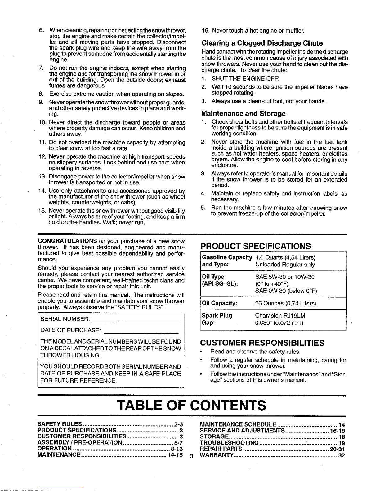
CONGRATULATIONS on your purchase of a new snow
thrower. It has been designed, engineered and manu-
PRODUCT SPECIFICATIONS
Gasoline Capacity 4.0 Quarts (4,54 Liters)
and Type: Unleaded Regularonly
Oil Type SAE 5W-30 or 10W-30
API SG-SL): (0°to +40°F)
SAE 0W-30 (below0°F)
Oil Capacity: 26 Ounces (0,74 Liters)
Spark Plug Champion RJ19LM
Gap: 0.030" (0,072 mm)
factured to give best possible dependability and perfor-
manGe.
Should you experience any problem you cannot easily
remedy, please contact your nearest authorized service
center. We have competent, well-trained technicians and
the proper tools to service or repair this unit.
Please read and retain this manual. The instructions will
enable you to assemble and maintain your snow thrower
properly. Always observe the "SAFETY RULES".
SERIAL NUMBER:
DATE OF PURCHASE:
THE MODELAND SERIAL NUMBERSWILL BE FOUND
ON A DECAL A-t-]-ACH EDTO THE REAR OF THE SNOW
THROWER HOUSING.
YOU SHOULD RECORD BOTH SERIAL NUMBERAND
DATE OF PURCHASE AND KEEP IN A SAFE PLACE
FOR FUTURE REFERENCE.
CUSTOMER RESPONSIBILITIES
• Read and observe the safety rules.
• Follow a regular schedule in maintaining, caring for
and using your snow thrower.
• Followthe instructions under "Maintenance" and "Stor-
age" sections of this owner's manual,
TABLE OF CONTENTS
SAFETY RULES ........................................................ 2-3
PRODUCT SPECIFICATIONS ...................................... 3
CUSTOMER RESPONSIBILITIES ................................ 3
ASSEMBLY / PRE-OPERATION ............................... 5-7
OPERATION ............................................................ 8-13
MAINTENANCE ..................................................... 14-15
MAINTENANCE SCHEDULE ..................................... 14
SERVICE AND ADJUSTMENTS ........................... 16-18
STORAGE................................................................... 18
TROUBLESHOOTING ................................................ 19
REPAIR PARTS..................................................... 20-31
WARRANTY ................................................................ 32
I
1
J
l
I
L
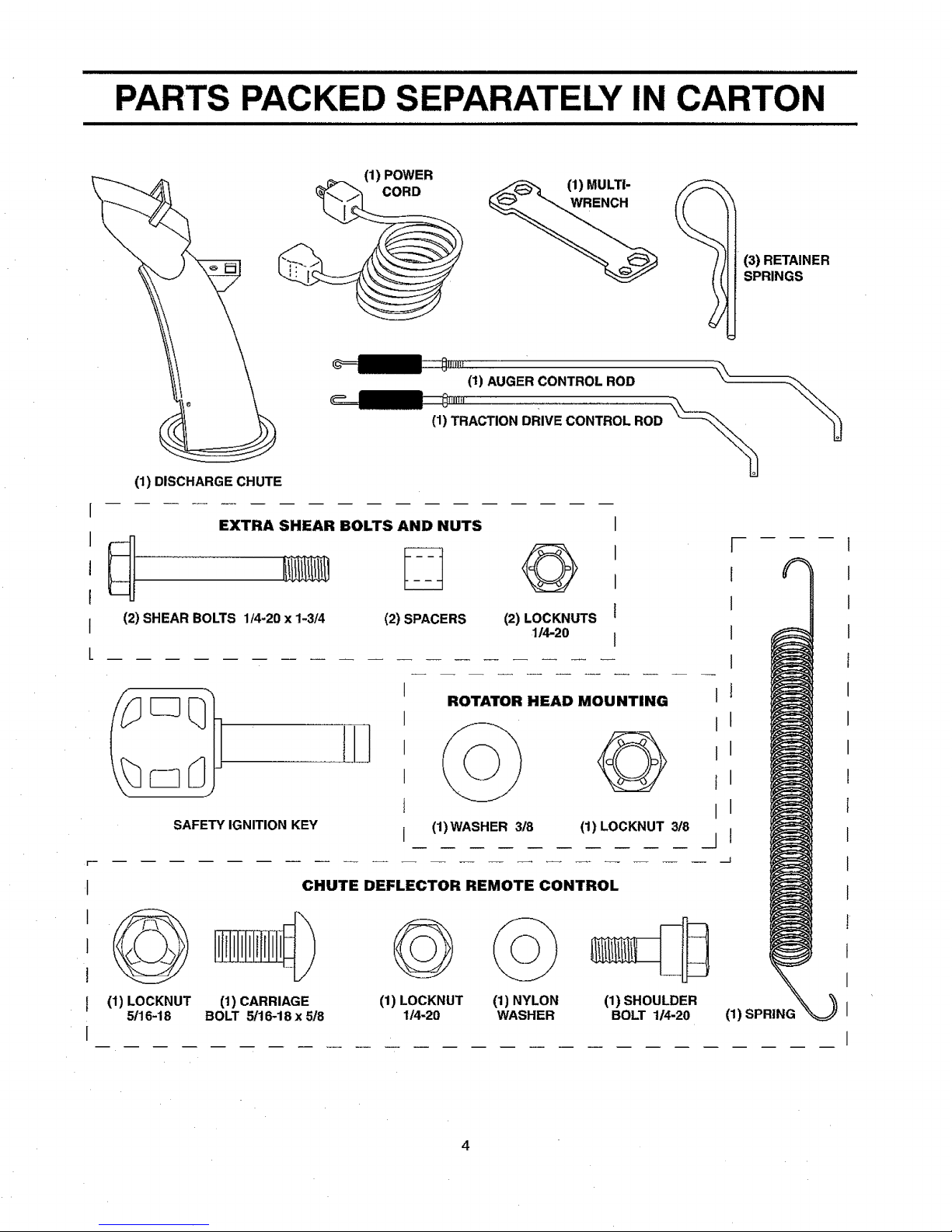
(1) POWER
(3) RETAINER
SPRINGS
(1) DISCHARGE CHUTE
(1) AUGER CONTROL ROD _--
(1) TRACTION DRIVE CONTROL ROD \_\
EXTRA SHEAR BOLTS AND NUTS
(2) SHEAR BOLTS 1/4-20 x 1-3f4 (2) SPACERS
O
(2) LOCKNUTS
114-20
I
I
SAFETY IGNITION KEY
I
I
I
I
I
ROTATOR HEAD MOUNTING
(1) WASHER 3/8 (1) LOCKNUT 318
CHUTE DEFLECTOR REMOTE CONTROL
(1) LOCKNUT
5/16-18
(1) CARRIAGE
BOLT 5/16-18 x 5/8
(1) LOCKNUT
1/4=20
(1)NYLON
WASHER
(1)SHOULDER
BOLT 1_-20
t
I
I
I
J
t
I
I
I
I
J
(1) SPRING
1
I
I
I
f
I
I
I
!
I
I
I
l
I
I
I
I
4
ASSEMBLY / PRE-OPERATION
Read these instructions and this manual inits entirety
before you attempt to assemble or operate your new
snow thrower. Reading the entire manual will familiar-
ize you with the unit, which will assist you in assembly,
operation and maintenance of the product.
"Yournewsnow thrower hasbeen assembled atthe factory
with the exception ofthose parts left unassembled for ship-
ping purposes. All parts such as nuts, washers, bolts, etc.,
necessary to complete the assembly have been placed in
the parts bag, Toensure safe and proper operation of your
snow thrower, all parts and hardware you assemble must
be tightened securely, Usethe correct tools as necessary
to ensure proper tightness.
REMOVE SNOW THROWER FROM CARTON
1. Remove all accessible loose parts and parts boxes
from carton.
2. Cut down all four corners of carton and lay panels flat.
3. Remove the two (2) screws securing the auger housing
to the pallet.
4. Remove all packing materials except plastic tie holding
speed control rod to lower handle.
5. Remove the two (2) plastic ties securing the upper
handle to the pallet.
6. Remove snow thrower from carton and check carton
thoroughly for additional loose parts.
HOW TO SET UP YOUR SNOW THROWER
TOOL BOX (See Fig, 10)
A toolbox is provided on your snow thrower. The toolbox is
located on top of the belt cover. Store the extra shear bolts,
nuts and multi-wrench provided in parts bag in the toolbox.
NOTE: The multi-wrench may be used for assembly of the
chute rotator head to snowthrower and making adjustments
to the skid plates.
UNFOLD UPPER HANDLE
1. Raise upper handleto the operatingposition and tighten
handle knobs securely.
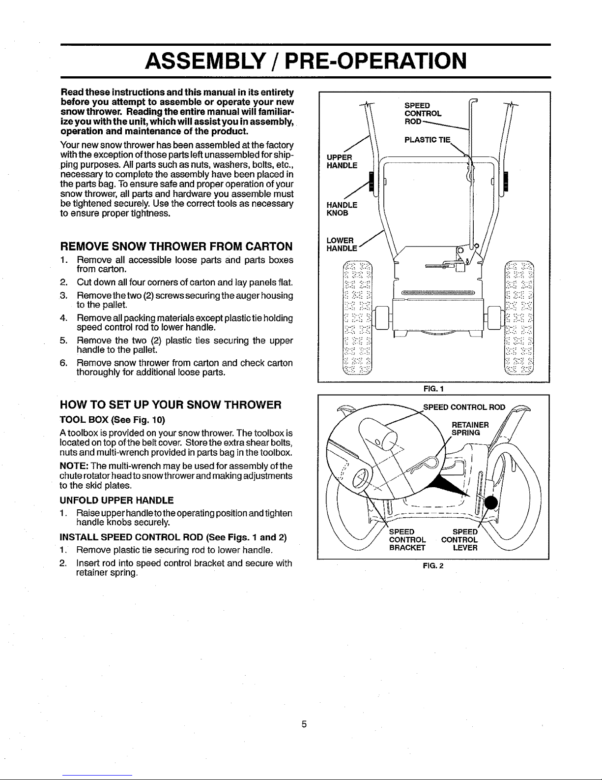
INSTALL SPEED CONTROL ROD (See Figs. 1 and 2)
1, Remove plastic tie securing rod to lower handle,
2, Insert rod into speed control bracket and secure with
retainer spring.
SPEED
CONTROL
UPPER
HANDLE
PLASTIC TIE
HANDLE
KNOB
LOWER
HANDLE
FIG. I
SPEED CONTROLROD
RETAINER
SPRING
SPEED SPEED
CONTROL CONTROL
BRACKET LEVER
FIG. 2
5
ASSEMBLY / PRE-OPERATION
|lHmlllllnUl ,n,,,,,im,,ll,lll,ll inl nlnll n I n i I ii I I I
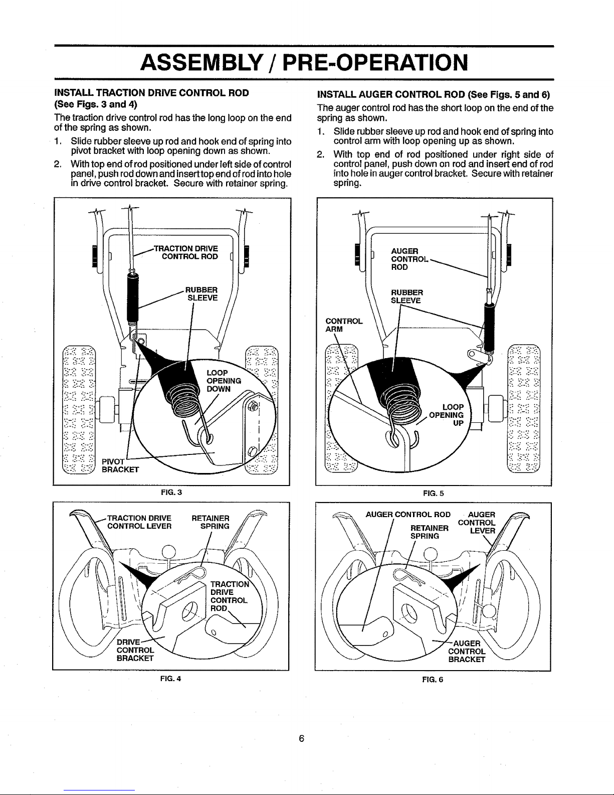
INSTALL TRACTION DRIVE CONTROL ROD
(See Figs. 3 and 4)
The tractiondrive controlrodhas the longlooponthe end
ofthespring as shown.
1. Slide rubber sleeveup rodand hookendof springinto
pivotbracketwith loopopeningdownas shown.
2. Withtop end ofrodpositionedunderleftsideof control
panel,pushroddownandinserttopendofrodintohole
in drive controlbracket. Secure with retainer spring.
INSTALL AUGER CONTROL ROD (See Figs. 5 and 6)
The auger controlrod has the shortlooponthe endofthe
springas shown.
1. Slide rubbersleeve uprodand hookend ofspringinto
controlarm withloopopeningup as shown.
2. With top end of rod positionedunder right side of
controlpanel, pushdown on rodand insertend ofrod
intohole inaugercontrolbracket. Securewithretainer
spring.
DRIVE
CONTROL ROD
BRACKET
FIG. 3
DRIVE RETAINER
SPRING
CONTROL
BRACKET
FIG. 4
CONTROL
ARM
AUGER
FIG. 5
AUGER CONTROLROD AUGER
CONTROL
RETAINER LEVER
SPRING
CONTROL
BRACKET
FIG. 6
=_... = ==...,
BLY / PRE-OPERATION
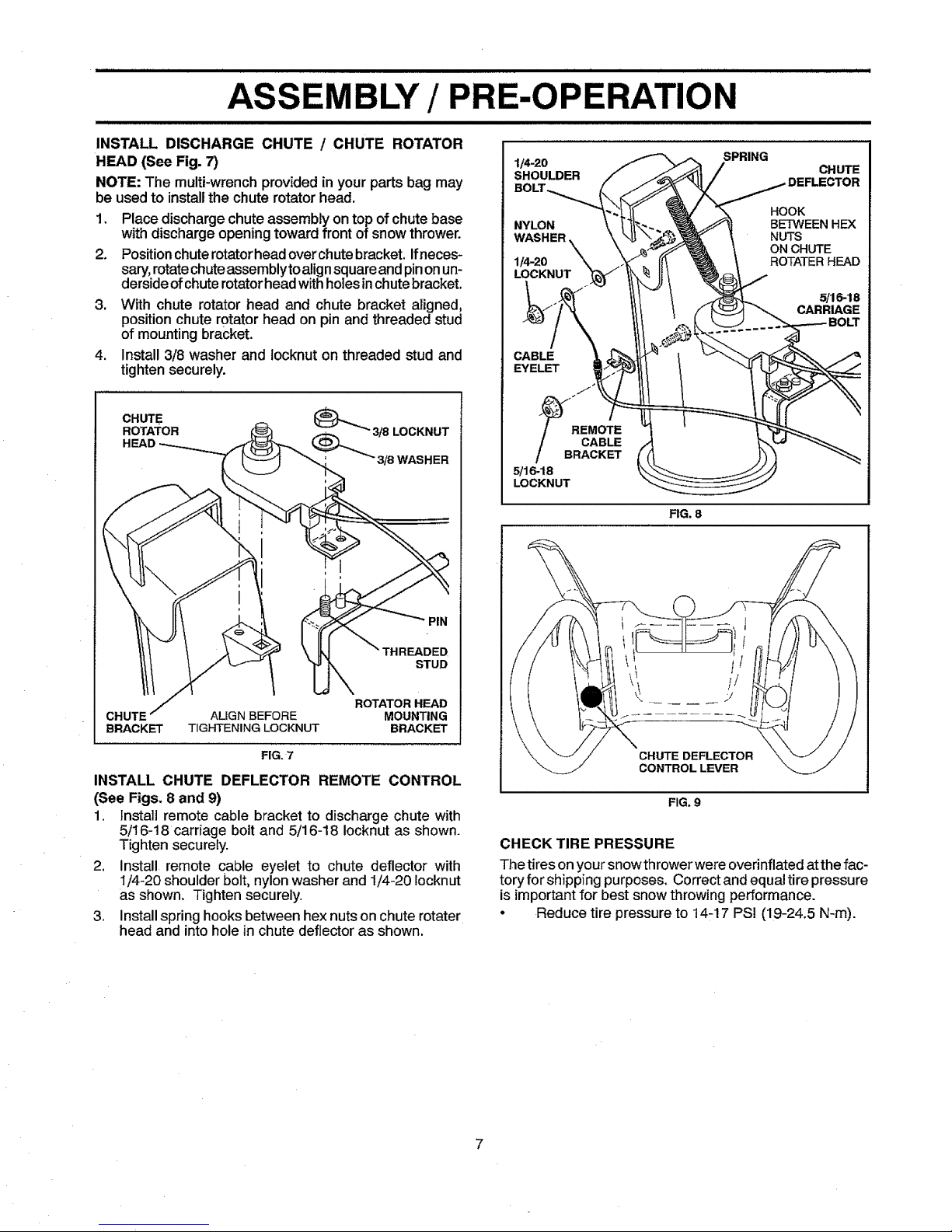
INSTALL DISCHARGE CHUTE / CHUTE ROTATOR
HEAD (See Fig. 7)
NOTE: The multi-wrench provided inyour parts bag may
be used to install the chute rotator head.
1. Place discharge chute assembly on top of chute base
with discharge opening toward front of snow thrower.
2. Positionchuterotatorheadoverchutebracket. Ifneces-
sary,rotatechuteassemblyto alignsquareand pinonun-
dersideofchute rotator headwithholesin chutebracket.
3. With chute rotator head and chute bracket aligned,
position chute rotator head on pin and threaded stud
of mounting bracket.
4. Install 3/8 washer and locknut on threaded stud and
tighten securely.
CHUTE (_._
ROTATOR 3/8 LOCKNUT
HEAD
3/8 WASHER
PiN
THREADED
STUD
ROTATOR HEAD
CHUTE ALIGN BEFORE MOUNTING
BRACKET TIGHTENING LOCKNUT BRACKET
FIG. 7
INSTALL CHUTE DEFLECTOR REMOTE CONTROL
(See Figs. 8 and 9)
1. Instal] remote cable bracket to discharge chute with
5/16-18 carriage bolt and 5/16-18 Iocknut as shown.
Tighten securely.
2, Install remote cable eyelet to chute deflector with
1,,'4-20shoulder bolt, nylon washer and 1/4-20 iocknut
as shown, Tighten securely.
3. Install spring hooks between hex nuts on chute rotater
head and into hole in chute deflector as shown.
1/4-20
SHOULDER
SPRING
CHUTE
NYLON
WASHER
1/4-20
LOCKNUT
HOOK
BETWEEN HEX
NUTS
ON CHUTE
ROTATER HEAD
5/16-18
CARRIAGE
CABLE
EYELET
J
_B _EMOTE
CABLE
RACKET
5/16-18
LOCKNUT
FIG. 8
CHUTE DEFLECTOR
CONTROLLEVER
FIG. 9
CHECK TIRE PRESSURE
The tires on your snow thrower were overinflated at the fac-
tory for shipping purposes. Correct and equaltire pressure
is important for best snow throwing performance.
• Reduce tire pressure to 14-17 PSi (19-24,5 N-m).
KNOW YOUR SNOW THROWER
RF_.ADTHIS OWNER'S MANUAL AND ALLSAFETY RULES BEFORE OPERATING YOUR SNOW THROWER. Compare
the illustrationswithyoursnowthrowerto familiarizeyourselfwiththe locationofvariouscontrolsand adjustments. Save
this manual forfuturereference.
I II IIII III
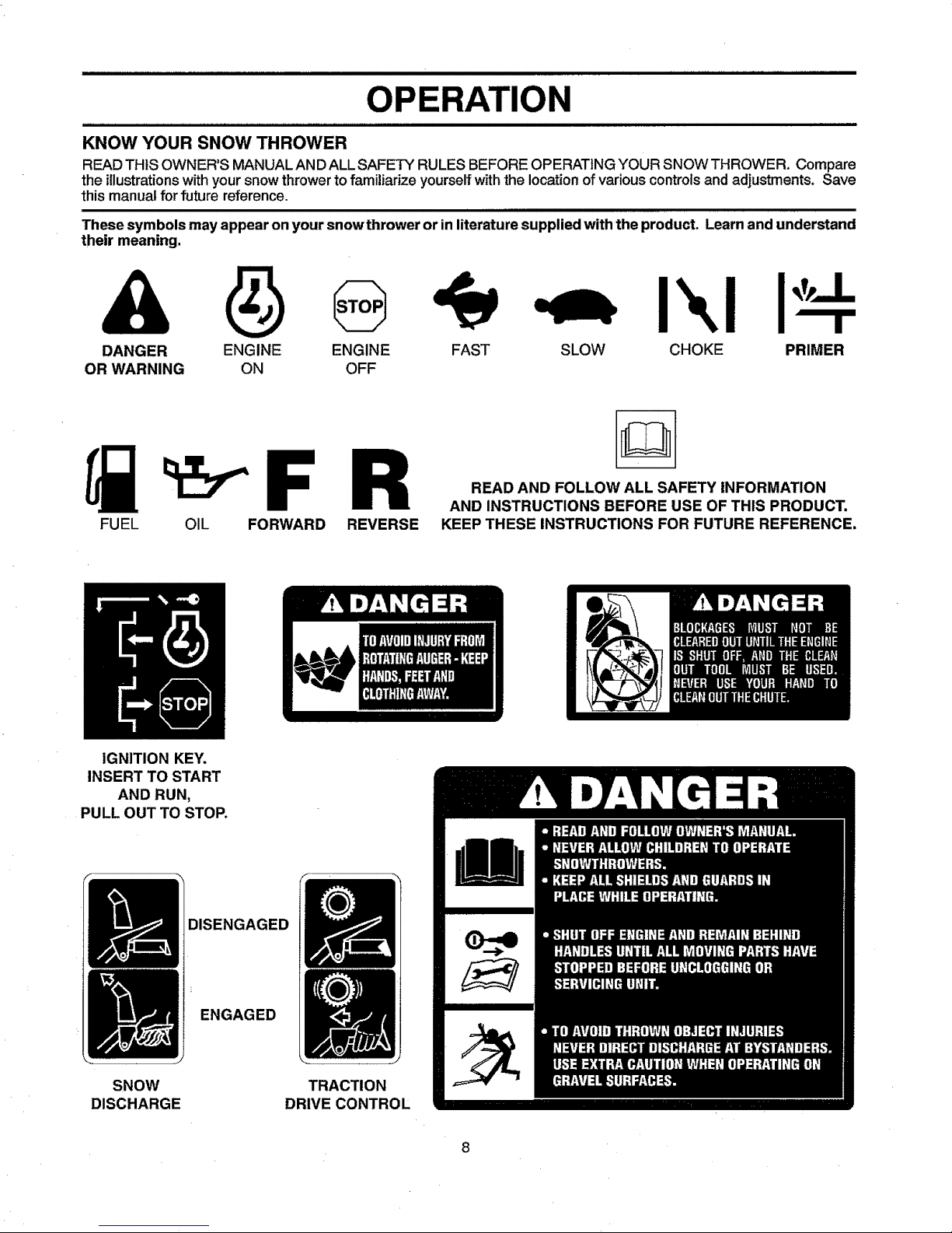
These symbols may appear on your snow thrower or in literature supplied with the product. Learn and understand
their meaning.
DANGER ENGINE ENGINE
OR WARNING ON OFF
I'.,i
FAST SLOW CHOKE PRIMER
FUEL OIL FORWARD REVERSE
READ AND FOLLOW ALL SAFETY INFORMATION
AND INSTRUCTIONS BEFORE USE OF THIS PRODUCT.
KEEP THESE INSTRUCTIONS FOR FUTURE REFERENCE.
IGNITION KEY.
INSERT TO START
AND RUN,
PULL OUT TO STOP.
DISENGAGED
SNOW
DISCHARGE
ENGAGED
TRACTION
DRIVE CONTROL
8

OPERATION
SPARK
PLUG.
SAFETY
IGNITION
CHOKE
CON-
THROTTLE
/ ENGINE
CONTROL
RECOIL
(AUXIL_R_
STARTER
HANDLE
POWER
CORD
PLUG
PRIMER
NOTE: ITEMS ABOVE
ARE SHOWN IN
THEIR TYPICAL
LOCATION ON THE
ENGINE. ACTUAL
LOCATION MAY VARY
WITH THE ENGINE
ON YOUR UNIT.
ELECTRIC
START
BUTTON
ENGINE OIL CAP AUGER
DIPSTICK CONTROL
LEVER DRIVE SPEED
FILLERcAP \-\\\_NTROL LEVER
CHUTE
DEFLECTOR
OIL
PLUG
DISCHARGE CHUTE CONTROLLEVER
DEFLECTOR REMOTE
CONTROLLEVER
DRIVE
CONTROL
LEVER
TURN
TRIGGER
DISCHARGE
CHUTE
FUEL
SHUT-OFF
VALVE OUT
TOOL
LIGHT
HANDLE
KNOB
MUFFLER
TOOLBOX
AUGERS
FIG. 10
,r,,,,,,,,f,,,,,irl ii ii ifll fill
MEETS A.N.S.I. SAFETY REQUIREMENTS
Our snowthrowersconformto the standardsof theAmerican National Standards Institute.
ilffll iii]]]]f] ilflll iiif ]r r]r]
Toolbox - used to store spare shear bolts, Iocknutsand
wrench.
Safety ignition key - must be inserted for the engine to
start and run. Remove when snow thrower is not in use.
Electric start button - used for starting the engine.
Recoil (auxiliary) starter handle- usedfor starting engine.
Drift cutter - used to cut throughdeep snowdrifts.
Primer - pumpsadditionalfuel from the carburetorto the
cylinderfor use when starting a cold engine.
Choke control - usedfor starting a coldengine.
LH and RHturn triggers- usedtosteer the snowthrower.
Throttle/engine control - used to select either FAST or
SLOW engine speed and to STOP the engine.
Traction drive control lever - used to engage power-pro-
pelled forward or reverse motion of snow thrower.
Auger control lever- used to engage auger motion (throw
snow).
Discharge chute control lever - used to change the di-
rection the snow is thrown.
Skid plate - used to adjust height of scraper bar from the
ground.
Deflector remote control lever - used to change the
distance the snow isthrown.
OP
The operation ofany snow thrower canresult
inforeign objects thrown intothe eyes, which
canresultinsevere eyedamage. Always wear
safetyglassesoreye shields whileoperating
yoursnowthrower orperformingany adjust-
ments or repairs. We recommendstandard safety glasses
or a wide vision safety mask worn over spectacles.
HOW TO USE YOUR SNOW THROWER
Know how to operate all controls before addingfuel or
attempting to start the engine.
STOPPING
TRACTION DRIVE
• Releasetractiondrivecontrolleverto stop theforward
or reverse movementofthe snowthrower.
AUGER
• Releasethe auger controlleverto stop throwingsnow.
ENGINE
1. Move throttlecontrolto "STOP" position.
2. Remove (do not turn) safety ignitionkey to prevent
unauthorizeduse.
NOTE: Never use choketo stop engine.
TO USE FUEL SHUT-OFF VALVE (See Fig. 11)
The fuel shut-off valve is located beneath the fuel tank on
the engine.Always operatethe snow throwerwiththe fuel
shut-off valve inthe OPEN position.
OFF
FIG. 11
TO USE THROTTLE CONTROL (See Fig. 12)
The throttlecontrolis located onthe engine.Always operate
the snow throwerwiththe engine atfull throttle.Fullthrottle
offersthe best snow throwerperformance.
FAST
SLOW
Q
TO USE CHOKE CONTROL (See Fig. 13)
The chokecontrolislocated on theengine.Usethe choke
controlwhenever you are starting a coldengine. Do not
use to start a warm engine.
, To engage choke, turn knob clockwise. Slowly turn
knob counterclockwise to disengage.
OFF
FIG. 13
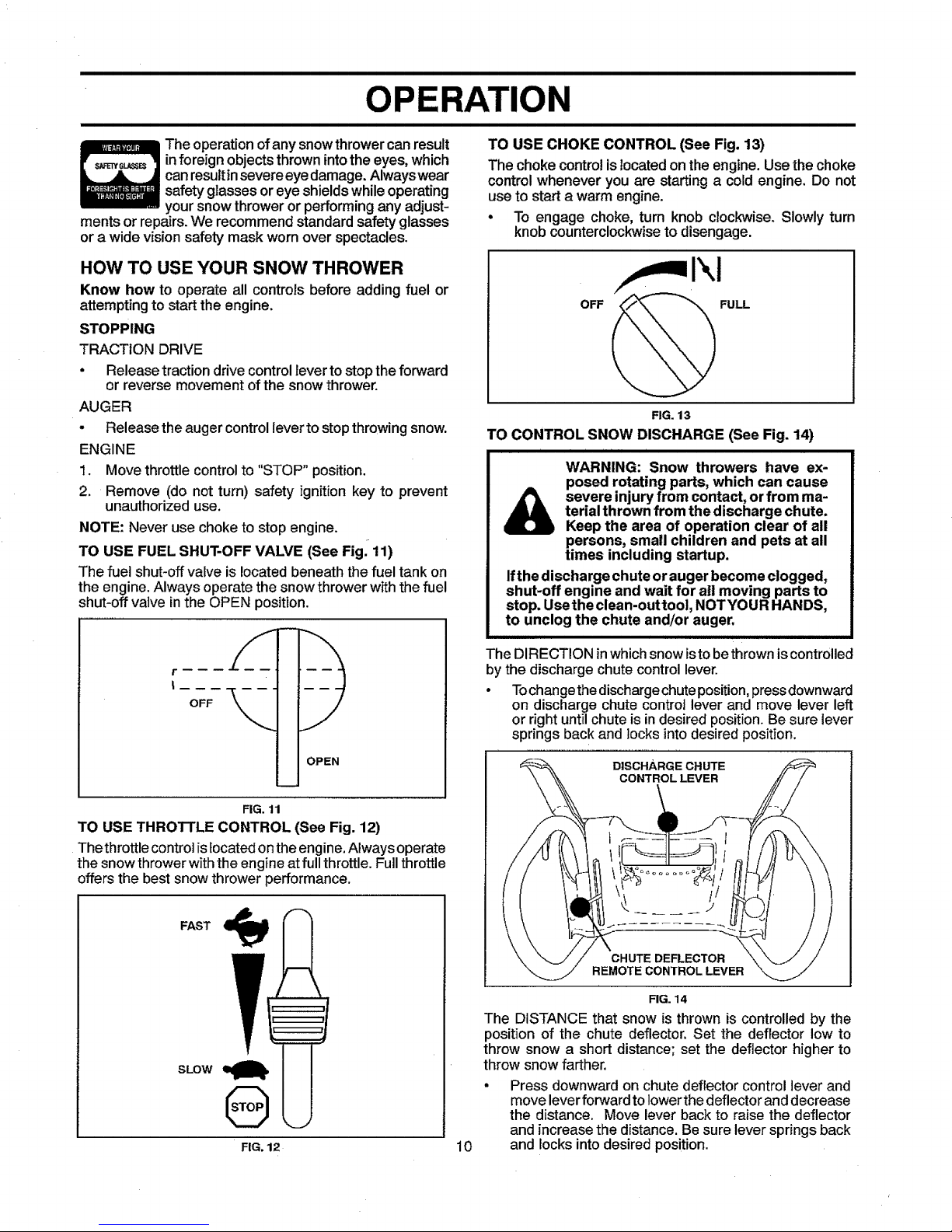
TO CONTROL SNOW DISCHARGE (See Fig. 14)
i i i i i
WARNING: Snow throwers have ex-
posed rotating parts, which can cause
severe injury from contact, or from ma-
terial thrown from the discharge chute.
Keep the area of operation clear of all
persons, small children and pets at all
times including startup.
Ifthe discharge chute or auger become clogged,
shut-off engine and wait for all moving parts to
stop. Usethe clean-outtoo], NOTYOUR HANDS,
to unclog the chute and/or auger.
The DIRECTION in which snow isto be thrown is controlled
by the discharge chute control lever.
• To change the discharge chute position, press downward
on discharge chute controt lever and move lever left
or right until chute is in desired position. Be sure lever
springs back and locks into desired position.
DISCHARGE CHUTE
CONTROLLEVER
CHUTE DEFLECTOR
REMOTE CONTROL LEVER
FIG. 14
The DISTANCE that snow is thrown iscontrolled by the
position of the chute deflector. Set the deflector low to
throw snow a short distance; set the deflector higher to
throw snow farther.
Press downward on chute deflector control leverand
move lever forward to lowerthedeflector and decrease
the distance. Move lever back to raise the deflector
and increase the distance. Be sure lever springs back
and locks into desired position.FIG. 12 10
 Loading...