

Poulan Pro P3314, P3314WS, P3314WSA, P3416, P3516PR Instruction Manual
...
Poulon
?
I
Manual de
Instrucciones
Man uel d'l
nstructions
P331
4
lP3314WS /
P3314WSA
P3416
/
P3516PR
/
P4018WM
P4O18WT
/
P3818AV
P4O1
8AV
/
P4O1 8AV
BH
For Occasional
Use
Only
WARNING:
Read
and
follow
all Safety
Rules and Operating
Instructions before
using
this
product.
Failure
to do so can
result
in
serious
injury.
ADVERTENCIA:
Lea
el
manual de instrucciones
y
srga
todas
las
advertencias
e en-
strucciones
de seguridad.
El no hacerlo
puede
resultar en
lesiones
graves.
AVERTISSEMENT
Lire
le manuel d'instructions
et bien
respecter
tous les avertisse-
ments
et
toutes
les instructions de
s6curit6.
Tout d6faut de
le
faire
oourrait entrainer
des blessures
oraves.
Please
do
not return
product
Por
favor,
no
devuelva
el
pro
Veuillez
ne
pas
retourner
le
P
1
-800-55
Register
your
product
online
Registre
su
producto
en
linei
Enregistrez
votre
produit
en
www.pou
Instruction
Manual
luct
to retailer.
producto
al
lugar
de
compra.
le
produit
au d€taillant.
,554-6723
line at:
inea en:
en
ligne d
I'adresse :
oulan.com
Poulan
9335
Harris Corners
Parkway
Charlotte,
NC 28269
Poulan
850
Matheson Blvd.
West
Mississauga, Ontario
L5V 084
545186804
Rev.
B
1131111
BRW
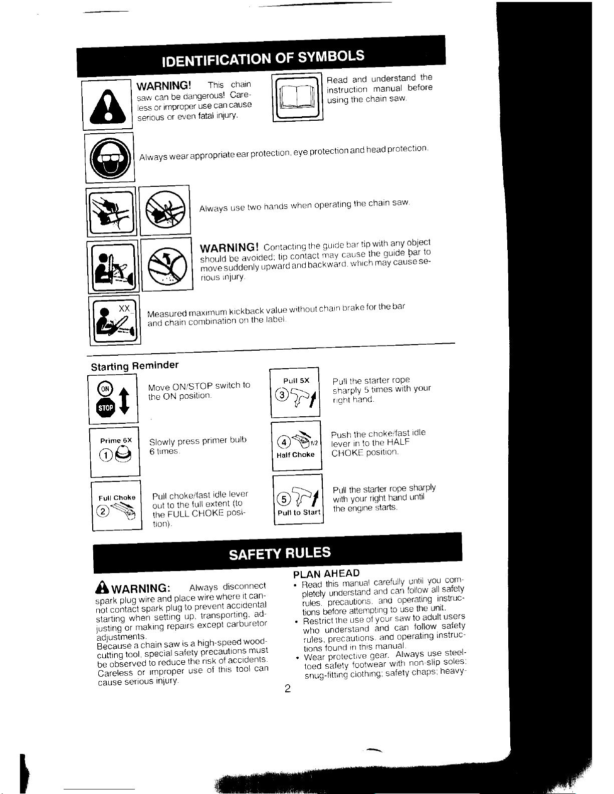
f-- ----l WARNING!
rhis
chain
lAl*r*1"'"AffiHH"1s
Read
and
understand
the
instruction
manual
before
using
the
chain
saw
t@
Alwavs
wear
appropriate
ear
protection
'
eve
protection
and
head
protectron
l-rll ,^. 1
ll$lll
W
I
o'**'
usetwo
hands
when
operatinsthechain
saw
:-,
I r.;l Il,<a I
HffiI;)Fix":.ilil1?fl
#i#i:Ti#;5!g"x,#is
l@lls)l
.usniurv
@
Measured
maxlmum
klckback
value
without
chaln
brake
for
the
bar
and chatn
combrnallon
or
lne
lannl
Starting
Re
E
ffiil
p9
ffil
le>
minder
Move
ON/STOP
switch
to
the
ON
Posltron
Slowly
Press
Primer
bulb
6
times.
Pull
choke/fast
idle
lever
oul
to
the
{ull extent
(to
the
FULL
CHOKE
Post-
lron).
Pull
the
starter
rope
sharply
5
times
wltn
Your
r
ght
hand.
Push
the
chokeltast
idle
lever
in
to
the
HALF
CHOKE
Posrtron
Pull
the
starter
rope
sharply
with
your rlght
hand
untll
the
engine
starts
f-",,';1
Ptr4
[t-s'l
I
Hattct'"t"
I
r-^ I
l@ld/l
I
Pulr
to
slart
I
AWnnNlHCl
AlwaYsdisconnect
;*ti
ptuc
wire
and
place
wire
where
rt
can
:ii?::t *i:f 4'l;*
L?'srul
s:
:;3"
:51
rrtt
"g
ot'
makrng
refarrs
excepl
cclrbLrrelor
B?iiHSi'in'
"
:?yr:^?,19:;:l?,:l$:i,
cuttinq
tool,
special
salety
Pre
[E'oO3"i*Oio
reduce
the
rrsh
o{ accidents
b'";#;.';;
,*PtoP"t
use
of
this
tool
can
cause
serious
InlurY
PLAN
AHEAD
'
3,:i"t'|,:.#;xi
:i;",'jx':il'-':il
;"'$;
i*:,:r,r*,:n;,
i!
1"
"j,?il:n;if
""
.
ii""tii"itn"
use
oi
your
saw
to adult
users
m:,
*,*:li
::,
;:l,
""il
;lii"l
f#:Y
.
ilVil
3iJ,!ryi
lfj,fu;
i,?0"
jL""l,
:""","
:
il
:.J J
:"ltY"?',Hi!!u
"
n uo,,
n " uu
u
'"t&;;"::
.
Wnn
the
enqrne
stopped.
hand carry
the
chair
saw
with
the
muffler
away
from
your
oodv,
and
the
quide
bar
ano
chain
to
the
rear preferabry-covered
wilh a scabDard
MAINTAIN
YOUR
SAW
IN GOOD
WORKING
ORDER
.
Have a
I chain
saw
service
performed by a
oual
fiecj
service
dealer
with
the
exception
o'f
the
rtems llsted
in the
mainlenance
sec
t on
of
thrs
manual.
Forexample,
if improp
er
tools
are
used
to
remove
or
hold
the
fly-
wheeLwhen
servicrng
the clutch.
structural
damaqe
to
the
ilytheel
can
occur
and
cause"the
flywheel
to burst
.
Ma^e
cerlarn
1fc saw
chaln
slops
moving
when
the
throttle
trigger
is
released
For
correction.
refer to
CARBURETOR
AD-
JUSTMENT.
.
Never
modify
your
saw
in any
way
.
Keepthe
handles
dry.
clean.
andfree
o{oil
or
{uel
mtxture.
.
Keep
fuel and
orl
caps.
screws,
and
fas
teners
securelY
tightened
.
Use
only
Poulan
accessories
and
r-eplace
ment
parts
as
recommended
HANDLE
FUEL
WITH CAUTION
.
Do
not smoke
while
handling
fuel
or
while
ooeratlnq
the saw.
.
Eliminateall
sources
of
sparks
orflame
in
the areas
where
fuel
is
mixed or
poured
There should
be
no smoking,
open
f lames,
or
work
that
could
cause
sparks
Allow
en
qine
to cool
betore
relueltng.
.
Always
have
fire extinguishlng
tools
avall-
able
it
vou
should
need
them
.
Mix and
pour
fuel in an
outdoor
area
on
bare
ground,
store
fuel
in a cool,
dry,
well
ventilated
place.
and
use
an
approved,
marked
container
for
all
fuel
purposes'
Wipe
up
allluel
spills
before
starting
saw
.
H,'tove at
least
1O
feet
(3
melers)
from
fuel-
inq site before
starting
englne.
.
Tu"rn
the
enqine
off and
let saw
cool
in
a
non'combustible
area,
nol on
dry
leaves'
straw,
paper,
etc.
Slowly
remove
fuel
cap
and
refuel
unit.
.
Storetheunitandfuel
in
anareawherefuel
vaDors
cannol
reach
sParhs
or
open
Ilames
{rom waler
heaters
electrlc
motols
or switches,
lurnaces,
etc.
KICKBACK
A wnnrutrucl
Avoid
kickback
which
can
result
in serious
iniury.
Kickback
is
the
backward,
upward
or sudden
forward
motion
of
lne
quide
bar occurrrng
when
lhe saw
charn
near
the upper
llp of the
gulde
bat
con
tacts
anv
obiect
such
as a
log or
branch,
or
when
th-e
w6od
closes
in and
pinches the
saw chain
in the cut.
Contacting
a
foreign
ob-
ject
in the
wood
can also
result
in
loss ol
chain saw
control.
.
Rotational
Kickback
can
occur
when
the
movinq
chain
contacts
an obiect
at the
upper
tiD
of the
quide
bar.
This contact
can
cause
tAe chain
jo
dig
into the
object,
which
stops
the chain
for an
instant.
The
result
is a
light-
ninq fast.
reverse
reaction
which
kicks
the
guide
bar
up
and back
toward
the operator'
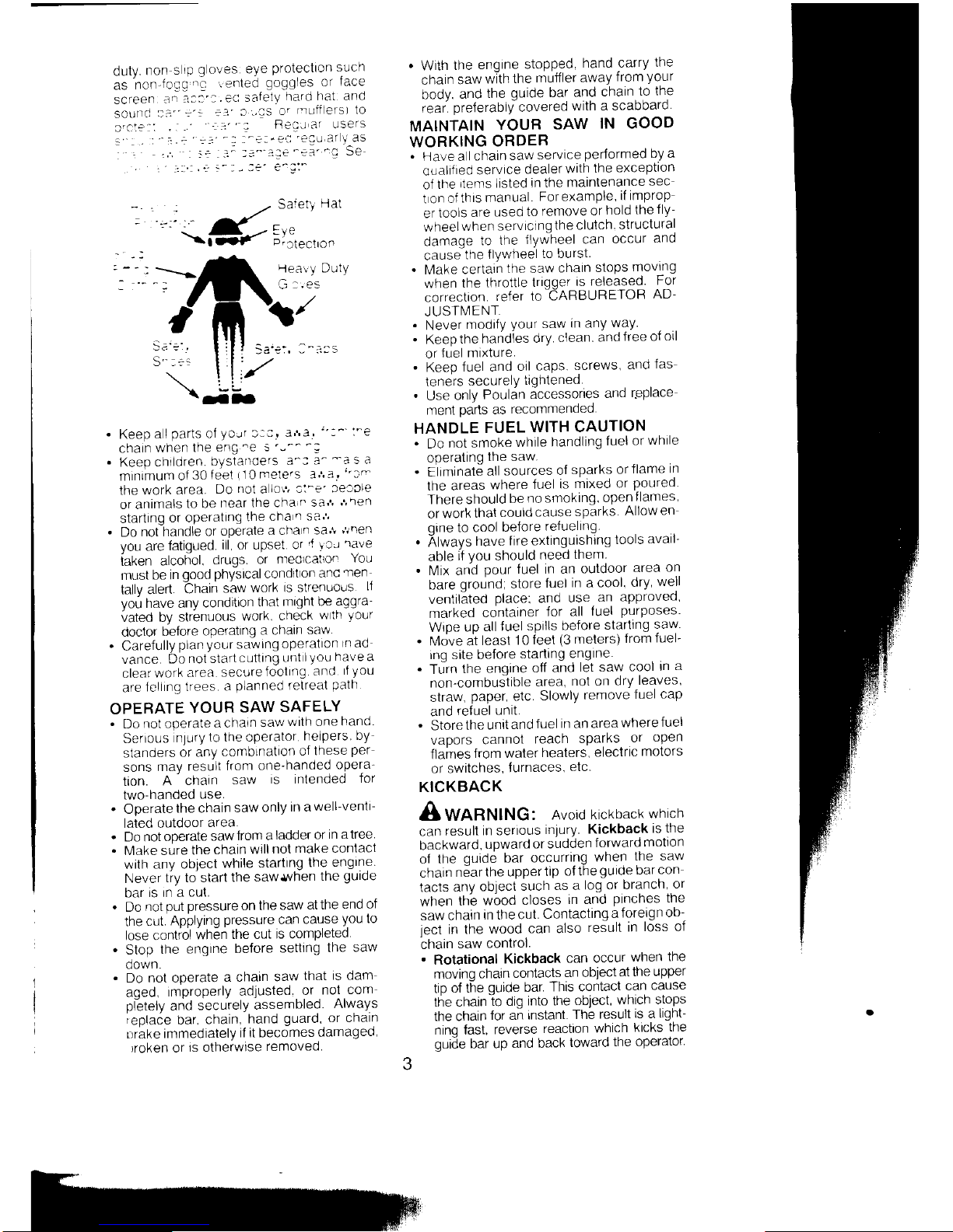
lealy Duty
G:.es
.
Keep
a I
parts
of
your
l::'
3r,e.
":^'
:'e
charn
when
the
eng'e
s
'--^'-:
.
Keep
chtldren.
bystarroers
a^:
3-
-a
s a
minamum
of
30 f eet
i1O
melers ar.
a,
"io
the work
area.
Do
not
a
lo\1
cl-e'
leacle
or animals
to be
near
the cha
n
saJ'
J''en
starting
or operatlng
the
cna
I
sa'1
.
Do
not handle
or
operate
a cna
n
sa'!
r/nen
you
are
fatigued.
ill, or upset
or
'l
lcr
rave
taken
alcohol.
drugs.
or
nreolcalron
You
must
be in
good
physical conditron
anc
ren
tallv alen.
Chain
saw
work
ls strenuous
ll
vou
have anv
conditron
that
nrlght
i)e aggra'
vated by
strbnuous
work.
check
wrth
your
doclor
before
opP'atlng
a
chain
sa*
.
Carefully
plan
your
sawlng
operatlon
rn
ad
vance.
Do
not startcuttlng
unt
I
you
nave
a
clearwork
area.
securefootlng.
and
f
you
are
fcll
ng trees.
a
planned
retreat
path
OPERATE
YOUR
SAW
SAFELY
.
Do
not operate
achaln
sawwlth
one
nano
Serrous
nlury
to the operator
helpers
by
standers
or any
comblnation
of Ihese
per
sons
may
result
lrom
one'nandeo
opera-
tion.
A-
chain
saw
is intended
for
two-handed
use.
.
Operate
the chain
saw
only
in a
well-ventl-
lated outdoor
area.
.
Do not
operate
sawfrom
a
ladder
or
in atree
.
[,4ake sure
the
chain
will
nol
make conlact
with
any object
while
startlng
the
engine.
Never
tiy to start
the
saw,lvhen
the
guide
Dar
rs In a
cut.
.
Do
not
put pressure on the
saw
at the
end ot
the
cut.
Applying
pressure
can
cause
you
10
lose contiol
when
the cut
is completed
.
Stop
the
engtne
before
setting
the
saw
oown.
.
Do not operate
a chain
saw
that
is dam
aged,
improperly
adjusted
or
nol
com
pletely
and
securely
assembled
Always
iepla6e
bar.
chain,
hand
guard, or chain
Luhke
immediately
if it becomes
damaged,
)roken or
is otherwise
removed
.a-
.
Pinch-Kickback
can
occur
when
the
the
wood
closes
in and
prnches the
moving
saw
chain
in the
cut
along
the
top of
the
oriOe
nar.
and
the
saw
chain
is suddenly
dtoooed.
This
sudden
stopping
of
the
chdrh
results
in a
reversal
of
the
chaln
force
used
to cut
wood
and
causes
the
saw
to
move
in the
opposite
direction
ol
the
chain
rotation.
The saw
is driven
stralght
back
toward
the
oPerator.
.
Pull-ln
can
occur
when
the
movlng
cnaln
contacts
a
foreign
object
In
the
wood
In
the
cut
alonq
the bottom
ol
the
guide bar
and
the
saw
chaln
is suddenly
stopped
This
sudden
slooDino
pulls
lhe saw
forward
and
away
lrom thd ooerator
and
could
eas
ly cause
the
operator
to
lose
conlrol
of the
saw
Avoid Pinch-Kickback:
.
Be
extremely
aware
ol sltuallons
o'
ob
itructions
that
can
cause
material
to
pinch
the
top
of or
otherwise
stop
the chaln
.
Do
not
cut
more
lhan
one
log at
a llme
.
Do
nol
twist
the
saw
as
the
bar
is with-
drawn
from an
undercut
when
bucklng
Avoid
Pull-ln:
.
Always
begin
cutting
with
the
engine
at
iull
speeil
and"lhe
saw
6ousing
against
wood
.
tjse wedoes
made
of
plastic
or
wood'
Never
use
metal
to hold
the
cut
open'
.
Beqin
and
continue
cutting
at
full speed
lf
the"chain
is
moving
at
a
slower
speed,
there
is
greater chance
of
kickback
occur-
ring.
.
Cut
one
loq at a
ttme.
.
Use extrefte
caution
when
re entering
a
Drevrous
cut.
.
bo
not attempt
cuts
slartinq
with
the tip
of
the bar
(olunqe
cuts).
.
Watch
for
snitting
logs
or other
forces
lhal
could
close
a cut-and
pinch
or
fall into
chatn
.
Use
the
Reduced-Kickback
Guide
Bar
and
Low
Kickback
Chain
specified
for
your saw.
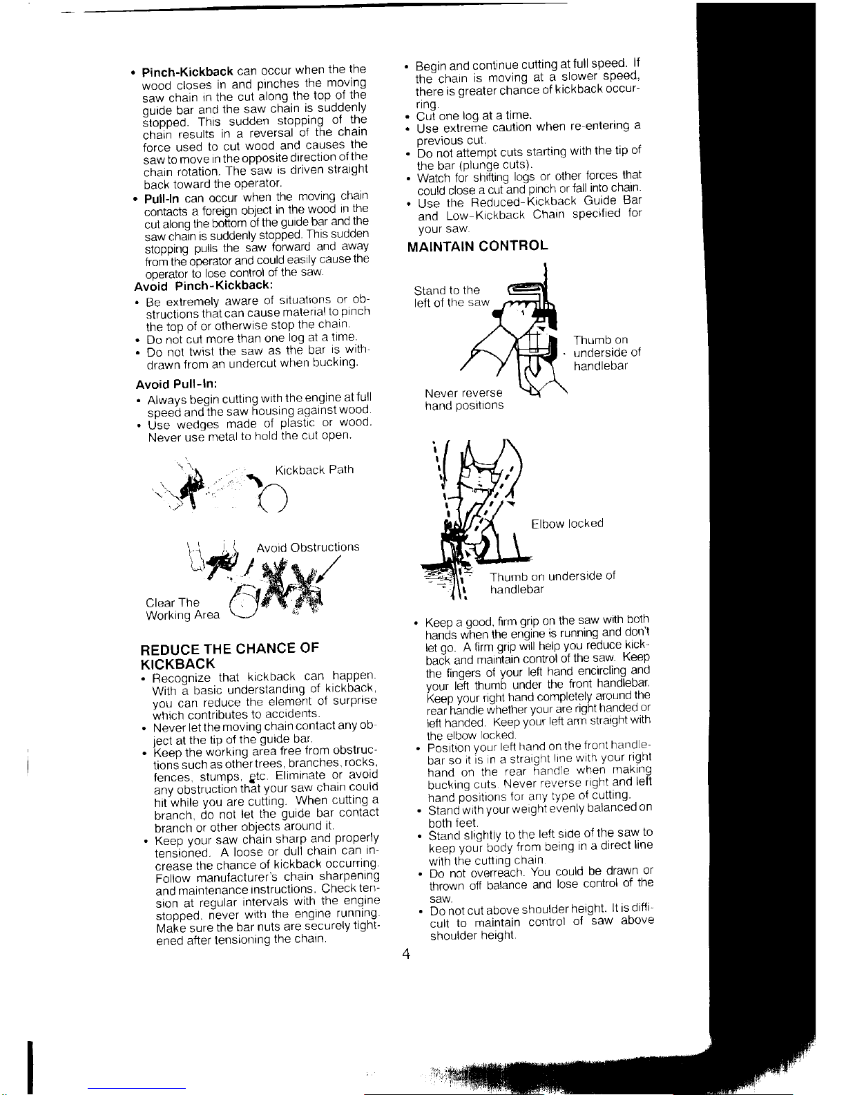
MAINTAIN
CONTROL
Stand
to
the
left of
the
saw
Thumb
on
underside
of
handlebar
Ki.k
\^"
/)
."+[
back
Path
Avoid
Obstructions
Elbow
locked
Thumb
on
underside
ol
handletlar
Clear
The
Working
Area
REDUCE
THE CHANCE
OF
KICKBACK
.
Recoonize
lhat
krckback
can
happen
With
; basic
underslanding
of
hickbach
Vou
can
reduce
the
element
of
surprlse
which contributes
lo
accidents
.
Never
let the
moving
chain
contact
any
ob
iect
at
the
tip o{
the
gurde bar'
.
keep
the
wbrking
area
free
from
obstruc-
tion; such
as
othertrees,
branches,
rocks,
fences,
stumps,
gtc.
Eliminate
or avold
anv
obstruction
that
your
saw
chain
could
hit while
you
are
cutting.
When
cutting
a
branch,
cio
not
let
the
guide
bar
contact
branch
or
other
objects
around
il
.
Keeo vour
saw
chain
sharp
and
propeny
tensioheO.
A loose
or
dull
chain
can
in-
crease
the chance
of
kickback
occurring
Follow
manufacturer's
chain
sharpening
and
maintenance
instructions
Check
ten-
sron
at
reqular
inlervals
with the
engine
stopped.
riever
wrth
the
engrne
running
Makb sure
the
bar
nuls
are
securely
tight-
ened
after
tensiolring
the
chaln
Keeo a oood.
fttm
qnp
on
lhe
saw
wilh
bolh
frinOs
w"fren
the
en-qine
rs runnlng
and
dont
let
oo.
A lirm
qrrp
wlll help
you reduce
kick'
baci and
marn]lain
control
ol
lhe saw
Keep
the
finoers
o{
Vour
left
hand
encircling
and
vour
leit
thumb
under
the
front
handlebar'
keep
yort
right
hand
completely
around
the
rear'hindle
whether
your
are
rlqht handecl
or
lefl
handed.
Keep
youl
left
arm
straront
wrln
the
elbow
locked.
'
Position
Vour
left
hand on
the
front
handle-
bar
so
it ls
n a straiqht
line
wlth
your rlgnl
hand
on
the
rear
6and1e
when
making
bucking
cuts
Never
reverse
right
and
lefi
hand
p"ositions for any
type
of cutting
.
Stand
with
your
weighi
evenly
balanced
on
both
teet.
.
Stand
sliohtlv
to
the
left side
of
the saw
to
keep
you-r
b6dy
from
being
in
a direct
line
wilh
the
cutttnq
cnaln
.
Do
not overreach.
You
could
be drawn
or
thrown
off
balance
and
lose
control
of
the
SAW,
.
Do
not
cut above
shoulder
height.
lt is difii-
cult
to
maintain
control
o{
saw
above
shoulder
height.
Never
reverse
hand
postlions
KICKBACK
SAFETY
FEATURES
A wnnHtxC:
ire for
owrng
features
. :+: i - . : -' sa*
to
l^e
p
'educe
the
:: :- L' . :.:a:'
^:r'/ever
SUCh
features
'-.
. z
- -3:e
ln s danger.
As a
'
:
-
-:r,
-s€- ::^al
.eiyonlyonsafetyde
':-
--s:'olow
all safety
Precau-
-
-
!1':31'r-S
and
maintenance
In this
..
-1
'-
'e
c
avord
kickback and
other
:-
.r
- : ^
: an
.esl,lt
in
senous
Inlirry.
.
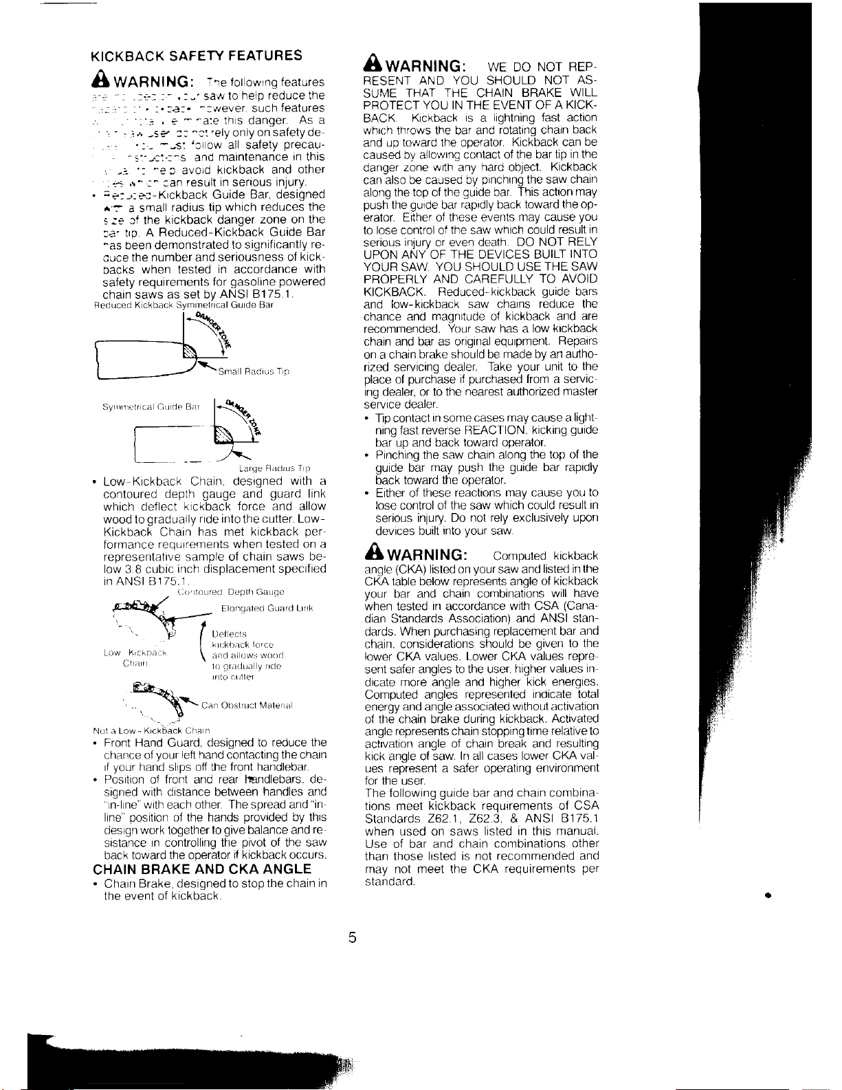
:+:-,:e:-Krckback
Guide
Bar, designed
^:
a small
radius tip which
reduces the
s:s
Jf the
kickback danger
zone on the
:a'
tro. A Reduced-Kickback
Guide
Bar
^as
been demonstrated
lo significantly
re-
cuce the
number and seriousness
of
kick-
backs
when lesled
in
accordance
with
salety
requirements
for
gasoline
powered
chain saws
as set by
ANSI 81 75.1
.
Feduced
K ckback SVmmetrrcal Gurde
Bar
Syrrlrrrclr ca Cu.ie
Bar
Larqe
Radlus T
P
Low
Kickback Chain, designed
with a
contoured
depth
gauge
and
guard
link
which deflect
klckback lorce and allow
wood to
gradually ride intothe cutter. Low-
Kickback Charn
has met kickback
per
formance
requrrements when tested
on a
representative sample of chain saws
be-
low 3.8 cubrc
inch displacement specified
in ANS| B
1 75.1 .
r
D
nlr'4..o'
pr[-ll
1-qdrp,),,...,.dt,,t
',
\*---=
-
tl I
\t
I
Lrrt
ect\
I
k
okbnck
{orce
Low
^K,c[baL]h \
ancl al ows
woori
(,Ila
rl
lo
qrn(iua y
lClC
rnto alrilef
\\
Can Obslnrct
l\"4:rlef a
Nol a Low.- Krckback Clra
I
.
Front Hand
Guard,
designed to reduce
the
chance of
your
lefi hand
contacting
the charn
rf
vour
hand sllDs off the
front handlebar.
.
Position of
front
and
rear lmndlebars. de-
sroned with distance between
handles and
'rn-lrne
with each other.
The spread and
"in
line
position
of the hands
provided
by
thrs
design work together
to
give
balance and
re
sistance
In
controlling
the
pivot
of the saw
back toward
the
operator
if kickback occurs.
CHAIN
BRAKE
AND
CKA
ANGLE
.
Chain
Brake, designed to stop
the
chain
in
the event of
kickback.
Awanlttllc: wE Do
Nor REP,
RESENT AND
YOU
SHOULD
NOT
AS-
SUN4E
THAT
THE
CHAIN
BRAKE
WILL
PROTECT YOU IN THE EVENT OF
A
KICK-
BACK
Krckback
is a lightning fast aclton
whrch throws the bar and
rotatang chain
back
and up
toward the operator.
Kickback can be
caused bv allowrng
contact of the bar
tip in the
danger
zone
w(h
any
hard
object.
Kickback
can also
b€ caused by
prnchrng
the saw chaln
along
the top of the
guide
bar.
This action
may
push
the
gulde
bar
rapidly
back
toward the op-
erator.
Efiher of these events
may cause
you
to lose control of
the
saw
whrch could
result in
serious
inrurv or even death.
DO NOT
RELY
UPON
ANY
OF
THE DEVICES BUILT
INTO
YOUR
SAW
YOU SHOULD USE
THE SAW
PROPERLY
AND
CAREFULLY
TO
AVOID
KICKBACK.
Reduced-kickback
guide
bars
and
low-kickback saw chains
reduce the
chance
and
magnrtude
o{
kickback and are
recommended.
Your saw has a low
kickback
chain
and bar as original equipment.
Repairs
on a chain
brake should be
made
by
an autho
rized
servicing
dealer.
Take
your
unit lo
the
olace
of
ourchase
if
ourchased
from a servic
ing
dealer,
or to the
nearest
aulhorized
master
servrce oearer.
.
llp contact
in
some
cases may cause a
light
ning fast reverse REACTION,
kicking
guide
bar uo and back
toward
ooeralor.
.
Pinching
the saw chain along the
lop of the
guide
bar may
push
the
guide
bar rapidly
back
toward the operator.
.
Either of
these reactions mav cause
vou
to
lose control ol
lhe
saw
whicii could
result rn
serious
injury. Do
not rely
exclusively
upon
devices
built
into
your
saw.
A
wnnrutruc: compuled
kickback
angle
(CKA)
listed on
your
saw and
lisled in the
CKA
table below represenls angle of
kickback
your
bar and chain combinations
will
have
when tesled
in
accordance
with CSA
(Cana-
dian Standards
Association) and
ANSI stan-
dards.
When
purchasing
replacement bar
and
chain. considerations should
be
given
to the
lower CKA values.
Lower
CKA
values
repre
senl safer
angles to the user,
higher values
in
dicate
more angle and higher kick energies.
Computed
angles
represented indicate total
energy
and angle associated
without activation
o{
the chain brake during
kickback. Activated
angle
represents chain stopping tame
relative to
actvation
angle of chain break and
resulting
kick angle ol saw.
In
all
cases lower CKA
val
ues represent a sa{er operating
environment
for the user.
The following
guide
bar
and chain combina
tions meel
kickback requrrements of CSA
Standards
262] , 262.3, &
ANSI 8175.'1
when used on saws
listed in this manual.
Use of bar and
chain combinations other
than those
listed is not
recommended and
may not meet the CKA
requirements
per
standard.
**
\-o
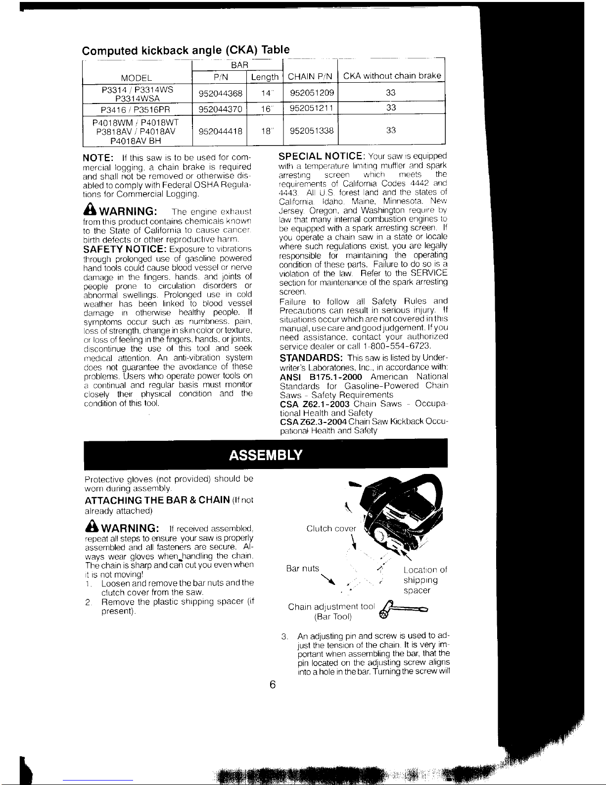
Computed
kickback angle
(CKA)
Table
NOTE:
lI this saw
is to be
used
for
com-
mercial
logging, a chain
brake
is required
and shall
not be
removed or otherwise
dls
abled
to comply
with Federal OSHA
Regula-
lrons
lor
Commercial
Loggtng
Awnnrutruc:
The engrne
exrausr
from this
product
contains
chemlcals
known
to the State
of California
to cause
cancer
birth de{ects
or
other
reproductlve
harm.
SAFETY
NOTICE:
Exposure
to vibratons
through
prolonged
use of
gasoline
powered
hand
tools could
cause blood
vessel
or nerve
damage
in the
fingers.
hands. and
Joints
of
people
prone
to orculatlon
dlsoroers or
abnormal
swellings.
Prolonged
use
in cold
weather
has been
linked to blood
vessel
damage
in otherwise
healthy
people.
lt
syrrptoms
occur
such
as
numbness.
paln,
oss of strength.
change
in sktn color
or texture,
or
loss
o{
Ieeling
in the fingers.
hands. or
lolnts.
d scontinue
the use
ol this tool
and seek
rredtcal attention.
An
anti-vibration
system
does
not
guarantee the avotdance
of
these
problems.
Users
who operate
power
tools on
a continual
and
regular
basis
musl monitor
closely
their
physical
condition
and the
condition
of this
tool.
SPECIAL
NOTICE:
Your
saw
rs equipped
with a temperature
ltnrttnq muff er
and spark
arrestrng
screen
wh ch
meets
the
requirements of Ca|lornra
Codes
4442 and
4443
Al
U S
torest
and
and
the states
ol
Calforn
a
ldaho N,4aine,
Minnesota.
New
Jersey
Oregon,
and
Washington
requlre
ily
law that
many internal combustion
eng
nes
to
be equrpped
with a spark
arresting
screen.
lf
you
operate
a chain
saw
in a state or
locale
where such
regulations exisl.
you
are
legally
responsible
for
maintaining the
operating
condition
of these
parts.
Failure
to do so
is a
violation of
the law.
Refer to lhe
SERVICE
sectaon
for maintenance
o{ the spark
arresting
screen.
Failure
to
follow all Safety
Rules
and
Precautions
can result
in serious
inlury.
lf
situations
occur
whrch are
not
covered
rn lnls
manual, usecareand
goodJUdgemenl.
llyou
need assistance.
contact
your
autnorlzeo
service
dealer
or call 1 800-554
6723.
STANDARDS:
This
saw
is
listed by Under
writer's
Laboratories,
lnc., in accordance
wrlh:
ANSI
8175.1-2000
American
National
Standards
for Gasoline
Powered
Chain
Saws
SaJety
Requirements
CSA
262.1-2003
Chain
Saws
OccuPa
tional
Health and
Safety
CSA 262.3-2004
Charn
Saw
Kickback Occu-
palional
Health and Safety
Protective
gloves
(not
provided)
snould be
worn during assembly.
ATTACHING
THE
BAR & CHAIN
(If
not
already
attached)
AWnnrutruC:
lf
received assembled.
'ppeat
all steps
to ensure
your
saw
rs
properly
assembled
and
all fasteners
are secure.
Al-
ways
wear
gloves
when.handling
the chain.
The chain is sharo
and can
cut
vou
even
when
t
is not moving!
1 . Loosen
and
remove the bar
nuls and
the
clutch
cover
from
the saw
2
Remove lhe
plastic
shipping
spacer
(il
oresenl).
\
\
Clutch cover
\
Bar
nuts
\
Chain adlustment
too
(Bar
Tool)
Locatl0n
ol
shrpprng
An adjusting
pin
and screw
is used
to ad-
iusl
the tensron
ol the charn.
lt
is very im
oortant
when assemblinq
the bar,
that the
bin
located
on tre adjus'iing
screw
aligns
into a hole in the bar.
Turnino
the screw
wrll
IVODEL
BAF
CHAIN
P1N
CKA
without chain
brake
P'N Lenoth
P3314
1
P3314WS
P3314WSA
952044368
952051
209 33
P3416 1
P3516PR
952044370
to
9520s1
21
1 33
P4018WlV
r
P4018WT
P3B18AV
i
P4O18AV
P4O1 BAV
BH
952044418
1B 952051
338
33

rrra,a:-:
:l -::-':-^: ]^ -p anc OO!Vn
the
: - a,',
-
':
::a :- S al !.6trnenl D€tore
yOU
:r= i
-
-
---:
-,:
:-€
car onto
the
saw. see
Insroe
view o1
cl
utch
cover
5
\
.,
Bar bolts
\
"...
.,\
Guide bar \-
'
6. Carefu ly
remove
the chain from
the
pack-
age
Hold
charn with the
drive
links
as
shown
Cutters
Depth
Gauge
Drive
Links
Place
chain over and behind
clutch
re-
tainer. fitting the
drive
links in
the clutch
orurn sprocKet.
Ft
botlom of drive links between the
teeth in
the sprocket in the nose
of
the
guroe
Dar.
Fit
chain drive
links
inlo bar
groove.
Pull
guide
bar forward until chain is snug
in
guide
bar
groove.
Ensure all drive
links
are in the
bar
groove.
Now. rnstall clutch
cover
making
sure
the
adJUSting
pin
is
positioned
in the low
er
hole in
the
guide
bar. Remember this
pin
moves the
bar
forward
and back-
ward
as the screw is turned.
: -::-e-t
located
on clutch cover
Adlust
ng Ptn
--'r
rne adjusting screw by hand coun-
:.'clockwise until the adjusting
prn
lust
:ouches
the
stop.
This
should allow the
prn
to be
near
the correct
posrtion.
Slide
guide
bar on
bar
bolts until
guide
bar stops against clutch drum sprocket
\
Clutch
Cover
12.
Install bar
nuts
and finger tighten only.
Once
the charn is tensioned.
you
will
need
to tighten bar nuts.
CHAIN
TENSION
(lnclud
ng units with chain
already
installed)
A
wnnrutruc: wear
protecrrve
groves
when handlang charn. The
chain
is sharp and
can cut
you
even
when it is
not moving.
NOTE: When
adjusting chain tension,
make sure the
bar
nuts
are
finger
tight only.
Attempting to tension
the chain when the bar
nuts are tight can cause
damage.
Checking the tension:
Use the screwdriver end of the
chain adjust-
ment tool
(bar
tool) to move
charn around
guide
bar. lf the
chain does
not rotate, it isloo
tighl.
lf
the chain
is
too loose, itwill sag below
the
bar.
.fi#
Chain
Adlustmen
Bar Nuls
Adrustino
^
Tool
'S;;;"
tBar
Tool)
Adjusting the
tension:
Chain tension is very important.
Chains
stretch during use. This rs
especially true
dunng the first few
times
you
use
your
saw.
Always
check chain tension each time be
fore
you
start the
chain saw.
1 . Loosen bar nuts u ntil
lhey are
fi nger
light
against the clutch cover.
2. Turn adjusting screw
clockwise until chain
solidly contacts
bottom of
guide
bar
rail.
9
10
CUTTEFS MUST FACE IN
DIIRECTION
OF
ROTATION
t1
 Loading...