


EN Operator's manual, pp. 2-28
FR Manuel d'utilisation, pp. 29-55
ES Manual de instrucciones, pp. 56-82
Please readtheseinstructionsand make
sure you understand them before using the
machine.
Life attentivement etbien assimiler le manuel
d_utilisationavantd_utiliserla machine
Lea detenidamente el manualde instrucciones
y aseg(_resedeentender sucontenido antes
de utiRzarla m_quina.

SYMBOL EXPLANATION
Symbols
WARNING: Clearing saws, brush- L_
cutters and trimmers can be dan- fro\
gerous! Careless or incorrect use it _
can result in serious or fatal / • •
injury to the operator or others.
Please read the operator's manual
carefully and make sure you r[]I ri.]
understand the instructions
before using the machine.
• A protective helmet where there
is a risk of falling objects
Always wear: @
• Hearing protection
• Approved eye protection
Max. speed of output shaft, rpm
Beware of thrown objects and _., "_
ricochets.
The operator of the machine
shall ensure, while working,
that no persons or animals come
closer than 50 feet (15 meters).
Machines fitted with saw blades
or grass blades can be thrown
violently to tt_e side when the
blade comes into contact with
a fixed object. The blade is
capable of amputating an arm
or leg. Always keep people
and animals at least 50 feet
(15 meters) from the machine.
Arrows which show limits for
handle mounting. _ t
max
10000 rpm
A
Use unleaded or quatity leaded %. /t_-_-)__.
gasoiine and two-stroke oil
mixed at a ratio of 2% (t :50).
Other symbols/decals on the machine
refer to special certification requirements
for certain markets.
Stop the engine by pushing
and holding the stop switch
in the STOP position. CAUTION!
The stop switch automaticalIy
returns to the start position.
In order to prevent unintentional
starting, the spark plug cap must be
removed from the spark plug when
assembling, checking and/or
performing maintenance.
Regular cleaning is required. _-]
Visual check.
always be used.
Approved eye protection must
Always wear approved protective
gloves.
Use anti-slip and stable boots.
Only use non-metalHc, flexible
cutting attachments, i.e. trimmer
heads with trimmer line.

CONTENTS
Contents
KEY TO SYMBOLS
Symbols ......................... 2
CONTENTS
Contents ........................ 3
Note the following before starting .... 3
WHAT IS WHAT?
What is what? ................... 4
GENERAL SAFETY PRECAUTIONS
Important ........................ 5
Personal protective equipment ...... 5
Machine's safety equipment ........ 6
Cutting equipment ................. 8
ASSEMBLY
Fitting the handlebar ............... 10
Fitting the harness and harness clamp 10
Fitting blades and trimmer heads .... 11
Fitting a blade guard, grass blade and
grass cutter ...................... 11
Fitting the trimmer guard and
trimmer head ..................... 12
FUEL HANDLING
Fuel safety ....................... 13
Fuel ............................ 13
Fuelling ......................... 14
STARTING AND STOPPING
Check before starting .............. t 5
Starting and stopping .............. 15
WORKING TECHNIQUES
General working instructions ........ 17
MAINTENANCE
Carburetor ....................... 20
Muffler .......................... 20
Spark plug ....................... 21
Air filter .......................... 21
Bevel gear ....................... 22
Sharpening grass cutters and grass
blades .......................... 22
Maintenance schedule ............. 23
TECHNICAL DATA
Technical data .................... 24
EMISSION CONTROL
WARRANTY STATEMENT ......... 25
Note the following before
starting:
Please read the operator's manual carefully.
Maintenance, replacement, or repair of the
emission control devices and system may
be performed by any nonroad engine repair
establishment or individual,
Jonsered has a policy of continuous product
development and therefore reserves the right
to modify the design and appearance of prod-
ucts without prior notice.
to noise can result in permanent I
hearing impairment. Always use ap-
_ WARNING: Long-term exposure
proved hearing protection.
The Emissions Compliance Period referred
to on the Emissions Compliance label indi-
cates the number of operating hours for
which the engine has been shown to meet
Federal emissions requirements,
Category C = 50 hours, B= 125 hours, and
A = 300 hours.
4t I 61 I 81 I
WARNING
Theengine exhaust fromthisproduct
contains chemicalsknownto the State
ofCalifornia to causecancer,birth
defectsor other reproductiveharm.
For reference, please fill out the following
information that will be needed for future
servicing of your trimmer:
Model Number:
Serial Number:
Purchase Date:
Purchased From:
WARNING: A clearingsaw,
&
brushcutter or trimmer can be
dangerous if used incorrectly or
carelessly, and can cause serious
or fatal injury to the operator or
others. It is extremely important
that you read and understand the
contents of this operator's manual.
WARNING: Under no circum-
&
stances may the design of the
machine be modified without the
permission of the manufacturer.
Always use genuine accessories.
Non-authorized modifications
and/or accessories can result
in serious personal injury or the
death of the operator or others.
Your warranty may not cover
damage or liability caused by the
use of non-authorized accesso-
ries or replacement parts.

©®
WHAT IS WHAT?
@
@
@
What is what?
1. Blade
2. Grease filler cap
3. Bevel gear
4. Cutting attachment guard
5. Shaft
6. Handlebar
7. Throttle control
8. Stop switch
9. Throttle lock
10. Harness clamp
11. Cylinder cover
12. Starter handle
13. Fuel tank
14. Choke control
15. Primer bulb
@
16. Air filter cover
17. Handle adjustment
18. Locking nut
19. Support flange
20. Support cup
21. Drive disc
22. Trimmer head
23. Socket spanner
24. Transport guard
25. Hex wrench
26. Locking pin
27. Harness
28. Start throttle button
29. Adjusting the throttle wire
30. Operator's manual
®

GENERAL SAFETY PRECAUTIONS
Important
IMPORTANT? The rnechine is only designed
for trimming grass, grass clearing and/or
forestry clearing.
The only accessories you can operate with
this engine unit are the cutting attachments we
recommend in the section on Technical data,
Never use the machine if you are tired, if you
have drunk alcohol, or if you are taking medi-
cation that could affect your vision, your judge-
ment or your co-ordination.
Never use the machine in extreme weather
conditions such as severe cold, very hot and/
or humid climates.
Wear personaI protective equipment. See in-
structions under the heading Personal protec-
tive equipment.
Never use a machine that has been modified
in any way from its original specification,
Never use a machine that is faulty, Carry out
the checks, maintenance and service instruc-
tions described in this manual. Some mainte-
nance and service measures must be carried
out by trained and qualified specialists, See
instructions under the heading Maintenance,
All covers and guards must be fitted before
starting, Make sure the spark plug cap and
lead are not damaged. Otherwise you could
get an electric shock, The machine operator
must ensure that no people or animals come
closer than 50 feet (15 meters) while working,
When several operators are working in the
same area, the safety distance should be at
least 50 feet (15 meters).
,_ WARNING: Using an incorrect
cutting attachment or an incorrectly
filed blade can increase the risk of
accidents.
_ WARNING: Never allow children
to use or be in the vicinity of the
machine. As the machine is equipped
with a spring-loaded stop switch and
can be started by low speed and
force on the starter handle, even
small children under some circum-
stances can produce the force neces-
sary to start the machine. This can
mean a risk of serious personal inju-
ry. Therefore remove the spark plug
cap when the machine is not under
close supervision.
Personal protective equipment
IMPORTANT? A clearing saw, brushcutter
or trimmer can be dangerous if used incor-
rectly or carelessly, and can cause serious
or fatal injury to the operator or others. It is
extremely important that you read and un-
derstand the contents of this operator's
manual. You must use approved personal
protective equipment whenever you use the
machine. Personal protective equipment
cannot eliminate the risk of injury but it will
reduce the degree of injury if an accident
does happen. Ask your dealer for help in
choosing the right equipment.
i_ WARNING: Listen out for warn-
ing signals or shouts when you are I
wearing hearing protection, Always I
remove your hearing protection as
soon as the engine stops.
HELMET
A helmet should be worn if the brush being
cleared is taller than 6 feet (2 meters).
HEARING PROTECTION
Wear hearing protection that provides
adequate noise reduction.
EYE PROTECTION
Always wear approved eye protection, if
you use a visor then you must also wear
approved protective goggles. Approved
protective goggles must comply with stan-
dard ANSI Z87.1.
GLOVES
Gloves should be worn when necessary,
e.g., when fitting cutting attachments.
BOOTS
Wear sturdy, non-slip boots.

GENERAL SAFETY PRECAUTIONS
CLOTHING
Wear clothes made of a strong fabric and
avoid loose clothing that can catch on
shrubs and branches. Always wear heavy,
long pants. Do not wear jewelry, shorts
sandals or go barefoot. Secure hair so it is
above shoulder level.
FIRST AID KIT
A first aid kit should be carried by opera-
tors of clearing saws, brushcutters or trim-
mers.
Machine's safety equipment
This section describes the machine's safe-
ty equipment, its purpose, and how checks
and maintenance should be carried out to
ensure that it operates correctly. See the
"What is what" section to locate where this
equipment is positioned on your machine.
The life span of the machine can be re-
duced and the risk of accidents can in-
crease if machine mah_tenance is not car-
ried out correctly and if service and/or re-
pairs are not carried out professionally, if
you need further information please contact
your nearest service workshop.
IMPORTANT! All servicing and repair work
on the machine requires special training. This
is especially true of the machine's safety
equipment, if your machine fails any of the
checks described below you must contact
/our service agent. When you buy any of our
3roducts we guarantee the availability of pro-
=essional repairs and service. If the retailer
who sells your machine is not a servicing
dealer, ask him for the address of your near-
est service agent.
Make sure the throttle control is locked at
the idle setting when the throttle lock is re-
leased,
Press the throttIe lock and make sure it re-
turns to its original position when you re-
lease it.
Check that the throttle control and throttle
lock move freely and that the return springs
work properly.
that has faulty safety equipment!
Follow the control, maintenance
and service instructions described
in this section, If your machine fails
l& ARNING: Never use a machine
any of these checks contact your
service agent to get it repaired.
Throttle lock
The throttle _ock is designed to prevent ac-
cidental operation of the throttle control
When you press the lock (A) (i.e. when you
grasp the handle) it releases the throttle
control (B). When you release the handle.
the throttle control and the throttle lock both
move back to their original positions. This
movement is controlled by two independent
return springs. This arrangement means
that the throttle control is automatically
locked at the idle setting.
See instructions under the heading Start,
Start the machine and apply full throttle,
Release the throttle and check that the
cutting attachment stops and remains at a
standstill If the cutting attachment rotates
with the throttle in the idle position then the
carburettor idle setting must be checked.
See instructions under the heading
Maintenance, _(_

GENERAL SAFETY PRECAUTIONS
Stop switch
Make sure the engine stops when you push
and hold the stop switch.
Cutting attachment guard
Harness quick release
There is an easily accessible, harness
quick release fitted at the front in case of an
emergency that requires you to free your-
self from the machine and harness.
See instructions under the heading Adjust-
ing the harness.
This guard is intended to prevent loose
objects from being thrown towards the
operator. The guard also protects the
operator from accidental contact with the
cutting attachment.
Check that the guard is undamaged and not
cracked. Replace the guard if it has been
exposed to impact or is cracked.
Always use the recommended guard for the
cutting attachment you are using. See the
"Technical data" section.
I_l ARNING: Never use a cutting
attachment without an approved
guard. See the section on "Technical
data". If an incorrect or faulty guard
is fitted this can cause serious
persona injury.
Use of incorrectly wound trimmer line or an
incorrect cutting attachment increases the
level of vibration.
_ WARNING: Overexposure to
vibration can lead to circulatory
damage or nerve damage in people
who have impaired circulation.
Contact your doctor if you experi-
ence symptoms of overexposure to
vibration. Such symptoms include
numbness, loss of feeling, tingling,
pricking, pain, loss of strength,
changes in skin color or condition.
These symptoms normally appear
in the fingers, hands or wrists. The
risk increases at low temperatures.
Check that the harness straps are correctly
positioned. Once the harness and machine
have been adjusted, check that the harness
quick release works correctIy.
Muffler
The muffier is designed to reduce the noise
level and to direct the exhaust gases away
from the operator.
CAUTION? Muffler is fitted with a catalytic
converter designed to reduce harmful ex-
haust gases.
The muffler on this unit is equipped with a
special spark arrestor mesh. The mesh
should be checked and. if necessary.
cleaned by a servicing dealer. A blocked
mesh will cause the machine to overheat,
which can lead to serious damage. Never
use a muffler with a defective spark arrestor
mesh. See the Maintenance section.
Muffler bolts
_$park arrestor mesh

GENERAL SAFETY PRECAUTIONS
For mufflers, it is very important that you
follow the instructions on checking, main-
taining, and servicing your machine.
Never use a machine that has a faulty
muffler.
0
Regularly check that the muffler is securely
attached to the machine.
_ WARNING: Mufflers fittedwith
catalytic converters get very hot dur-
ing use and remain so for some time
after stopping. This also applies at
idle speed. Contact can result in
burns to the skin. Remember the risk
of fire!
_ WARNING: The inside of the
muffler contain chemicals that may
be carcinogenic. Avoid contact with
these elements in the event of a
damaged muffler.
_1 WARNING: Bear in mind that:
Engine exhaust fumes contain car-
bon monoxide, which can cause
carbon monoxide poisoning. For
this reason you should not start or
run the machine indoors, or any-
where that is poorly ventilated.
The exhaust fumes from the engine
are hot and may contain sparks
which can start a fire. Never start
the machine indoors or near com-
bustible material!
Locking nut
A locking nut is used to secure some types
of cutting attachment.
When fitting, tighten the nut in the opposite
direction to the direction of rotation of the
cutting attachment. To remove it. undo the
nut in the same direction as the cutting at-
tachment rotates. (CAUTION! The nut has
a left-hand thread.) Tighten the nut using
the socket spanner.
The nylon lining inside the locking nut must
not be so worn that you can turn it by
hand. The lining should offer a resistance
of at least 1.5 Nm. The nut should be re-
)laced after it has been put on approx. 10
times.
Cutting equipment
This section describes how to choose and
maintain your cutting equipment in order to:
• Reduce the risk of blade thrust.
• Obtain maximum cutting performance.
• Extend the life of cutting equipment.
IMPORTANT!
Only use cutting attachments with the guards
we recommend! See the section on
"Technical data".
Refer to the instructions for the cutting attach-
ment to check the correct way to load the
trimmer line and the correct line diameter.
Keep the teeth of the blade correctly sharp-
ened! Follow our recommendations. Also re-
fer to the instructions on the blade packaging.
Maintain the correct blade setting! Follow our
instructions and use the recommended file
gauge.
_ WARNING: Always stop the en-
gine before doing any work on the
cutting attachment. This continues
to rotate even after the throttle has
been released. Ensure that the
cutting attachment has stopped
completely and disconnect the
lead from the spark plug before
you start to work on it.
_lb WARNING: Using an incorrect
cutting attachment or an incorrect-
ly sharpened blade increases the
risk of kickback.

GENERAL SAFETY PRECAUTIONS
Cutting equipment
Grass blades and grass cutters are in-
tended for cutting coarse grass.
A trimmer head is intended for trimming
grass.
I;t_ :"<h _#
General rules
Only use cutting attachments with the
guards we recommend! See the section on
Technical data.
Keep the teeth of the blade correctly sharp-
ened! Follow our instructions and use the
recommended file gauge. An incorrectly
sharpened or damaged blade increases the
risk of accidents.
Sharpening grass cutters and
grass blades
• See the cutting attachment packaging for
correct sharpening instructions. Sharpen
blades and cutters using a single-cut flat file.
• Sharpen all edges equally to maintain the
balance of the blade.
,_ WARNING: Always discard a
blade that is bent, twisted, cracked,
broken or damaged in any other
way. Never attempt to straighten
a twisted blade so that it can be re-
used. Only use original blades of
the specified type.
Trimmer head
IMPORTANT!
Always ensure the trimmer line is wound
tightly and evenly around the drum, other-
wise the machine will generate harmful
vibration.
• Only use the recommended cutting at-
tachments. See the section on "Technical
data".
Check the cutting attachment for damage
or cracks. A damaged cutting attachment
should always be replaced.
• Smaller machines generally require small
trimmer heads and vice versa. This is be-
cause when clearing using trimmer line
the engine must throw out the trimmer
line radially from the trimmer head and
overcome the resistance of the grass
being cleared.
• The length of the trimmer line is also im-
portant. A longer trimmer line requires
greater engine power than a shorter
trimmer line of the same diameter.
• Make sure that the cutter on the trimmer
guard is intact. This is used to cut the
trimmer line to the correct length.
• To increase the life of the trimmer line it
can be soaked in water for a couple of
days. This will make the line tougher so
that it lasts longer.

ASSEMBLY
NOTE: Make sure unit is assembled cor-
rectly as shown in this manual.
Fitting the handlebar
Remove the screw at the rear of the
throttle handle.
Slide the throttle handle onto the right
side of the handlebar (see illustration).
Align the screw hole in the throttle han-
dle with the hole in the handlebar.
Refit the screw in the hole in the rear of
the throttle handle.
Screw the screw through the handle and
handlebar. Tighten the screw.
Fit the mounting components as shown.
//
NOTE: Fit throttle wire in groove of lower
harness clamp before tightenh_g screws.
• Insert two screws h_to the screw hotes.
• Secure harness clamp by tightening
screws with a hex wrench.
Adjusting the harness
• At the front of the harness is an easi]y
accesible quick release. Use the quick
release in any emergency situation that
requires you to free yourself from the
machine and harness.
...... _.=- j
Spreading the load on your
shoulders
• A well-adjusted harness and machine
makes work much easier.
• Put on the harness. Adjust the harness
for the best working position. Tension the
side straps so that the weight is evenly
distributed across both shoulders.
• The handlebar mounth_g must be fitted
between the arrows on the shaft.
• Tighten the screws with a hex wrench.
Fitting the harness
brushcutter, it must always be
hooked securely to the harness.
Otherwise, you will be unable to
control the brushcutter safely.
This can result in injury to yourself
I_ib WARNING: When using a
or others. Never use a harness with
a defective quick release.
Proper harness and handlebar adjust-
ments must be made with the engine com-
pletely stopped before using unit.
Fitting the harness clamp
• Place the upper harness clamp over the
shaft and position the lower harness
clamp under the shaft. Align the upper
and lower clamp screw holes. Clamp
must be fitted above the arrow on the
shaft (see illustration).
NOTE: it may be necessary to relocate
the harness clamp on the shaft for proper
batancing of unit.

ASSEMBLY
Correct height
Adjust the harness so that the cutting at-
tachment is parallel to the ground.
Correct balance
Let the cutting attachment rest lightly on
the ground. If you use a grass blade, it
shouM balance about 10 cm above the
ground to prevent contact with stones and
the like. Adjust the position of the harness
clamp to balance the unit correctly.
Fitting blades and trimmer
heads
• When fitting the cutting attachment it is
extremely important that the raised section
on the drive disc/support flange engages
correctly in the centre hole of the cutting
attachment. If the cutting attachment is
fitted incorrectly it can result in serious and/
or fatal personal injury,
Fitting a blade guard, grass
blade and grass cutter
Hook the btade guard/combination guard
(A) onto the fitting on the shaft and secure
with the bolt,
OAUTION? Use the recommended blade
guard, See the Technical data section.
Fit the drive disc (B) on the output shaft.
Turn the blade shaft until one of the
hotes in the drive disc aligns with the
corresponding hole in the gear housing,
Insert the locking pin (C) in the hole to
tock the shaft,
Place the blade (D), support cup (E) and
support flange (F) on the output shaft.
Fit the nut (G). The nut must be tight-
ened to a torque of 35-50 Nm (3,5-5
kpm), Use the socket spanner in the tool
kit, Hoid the shaft of the spanner as
close to the blade guard as possible. To
tighten the nut, turn the spanner in the
opposite direction to the direction of rota-
tion (CAUTION? left-hand thread),
_IbWARNING: Never use a cutting
attachment without an approved
guard. See the section on Techni-
cal data. If an incorrect or faulty
guard is fitted this can cause seri-
ous personal injury.
IMPORTANT]
if a grass blade is to be used, the machine
must be equipped with the correct handle-
bar, blade guard and harness.

ASSEMBLY
Fitting the trimmer guard and
trimmer head
• Fit the correct trimmer guard (A) for use
with the trimmer head. Hook the trimmer
guard/combination guard onto the fitting
on the shaft and secure with the bolt (D).
ff
,_ _" U
I
A
• Fit the drive disc (B) on the output shaft.
• Turn the shaft until one of the holes in the
drive disc aligns with the corresponding
hole in the gear housing,
• Insert the locking pin (C) in the hole to
lock the shaft.
• Screw on the trimmer head (H) in the op-
posite direction to the direction of rota-
tion,
B
• To dismantle, follow the instructions in
the reverse orden

FUEL HANDLING
Fuel safety
Never start the machine:
1. If you have spilled fuel on it. Wipe off the
spillage and aIIow remaining fuel to evapo-
rate.
2. If you have spilled fuel on yourseIf or your
clothes, change your clothes. Wash any
part of your body that has come in contact
with fuel. Use soap and water.
3. If the machine is leaking fuel. Check regu-
larly for leaks from the fuel cap and fuel
_ines.
Transport and storage
• Store and transport the machine and fuel
so that there is no risk of any leakage or
fumes coming into contact with sparks or
naked flames, for example, from electri-
cal machh_ery, e_ectric motors, electrical
relays/switches or boilers.
• When storing and transporting fue_ al-
ways use approved containers intended
for this purpose.
• When storing the machine for long peri-
ods the fuel tank must be emptied. Con-
tact your local gas station to find out
where to dispose of excess fuel.
• Ensure the machine is cleaned and that
a complete service is carried out before
tong-term storage.
• The transport guard must always be
fitted to the cutting attachment when the
machine is being transported or in stor-
age.
• In order to prevent unintentional starting
of the engine, the spark plug cap must
always be removed during long-term
storage, if the machine is not under
close supervision and when performing
all service measures.
dling fuel. Bear in mind the risk of
_lb ARNING: Take care when han-
fire, explosion and inhaling fumes.
Fuel
CAUTION! The machine is equipped with a
two-stroke engine and must always be run
using a mixture of gasoline and two-stroke
engine oil. It is important to accurately mea-
sure the amount of oil to be mixed to ensure
that the correct mixture is obtained. When
mixing small amounts of fuel, even small
inaccuracies can drastically affect the ratio
of the mixture.
Gasoline
CAUTION! Always use high quality
unleaded gasoline.
• This engine is certified to operate on
unleaded gasoline.
• The lowest recommended octane rating is
87. If you run the engine on lower octane
rating than 87, "knocking" can occur. This
leads to an increased engine tempera-
ture, which can result in a serious engine
breakdown=
• When working at continuous high revs, a
higher octane rating is recommended.
Two-stroke oil
• For best results and performance, use
JONSERED two-stroke oil, which is
specially formulated for our two-stroke
engines. Mixture 1:50 (2%).
• To maximize the life of your trimmer, you
may choose to use a high quality syn-
thetic oil formulated for two-stroke
engines. Mixture 1:50 (2%).
• Never use two-stroke oil intended for
water-cooled outboard engines,
sometimes referred to as outboard oil.
• Never use oil intended for four-stroke
engines.
Gasoline
U.S. gallon
1
21/2
5
Two-stroke oil
2% (1:50)
U.S. fl. oz,
2 1/2
61/2
t2 7/8
are highly inflammable and can
cause serious injury when inhaled
or allowed to come in contact with
the skin, For this reason observe
caution when handling fuel and
l_i ARNING: Fuel and fuel fumes
make sure there is adequate ven-
tilation.

FUEL HANDLING
Mixing
• Always mix the gasoline and oil in a
clean container intended for fuel.
• Always start by filling half the amount of
the gasoline to be used. Then add the
entire amount of oil, Mix (shake) the fuel
mixture, Add the remaining amount of
gasoline.
• Mix (shake) the fuel mixture thoroughly
before filling the machine's fuel tank,
• Do not mix more than one month's sup-
ply of fuel at a time.
• If the machine is not used for some time,
the fuel tank should be emptied and
cleaned.
verter muffler gets very hot during
and after use. This also applies
during idling. Be aware of the fire
hazard, especially when working
_ ARNING: The catalytic con-
near flammable substances and/or
vapors.
Fuelling
WARNING: Taking the following
&
precautions, will lessen the risk of
fire:
Do not smoke or place hot objects
near fuel.
Always shut off the engine before
refueling.
Always stop the engine and let it
cool for a few minutes before refu-
elling.
When refueling, open the fuel cap
slowly so that any excess pressure
is released gently.
Tighten the fuel cap carefully after
refueling.
Always move the machine away
from the refueling area before
starting.
• Clean the area around the fuel cap,
Contamination in the tank can cause
operating problems.
• Ensure that the fuel is well mixed by shak-
ing the container before filling the tank.
in.lOfeet
3 meters) L_r'_
14

STARTING AND STOPPING
Check before starting
• Check the blade to ensure that no cracks
have formed at the bottom of the teeth or
by the centre hoIe. The most common rea-
son why cracks are formed is that sharp
corners have been formed at the bottom of
the teeth while sharpening or that the blade
has been used with dull teeth. Discard a
blade if cracks are found.
• Check that the support flange is not
cracked due to fatigue or due to being
tightened too much. Discard the support
flange if it is cracked.
• Ensure the locking nut has not lost its cap-
tive force. The nut tock should have a
locking force of at least 1.5 Nm. The tight-
ening torque of the locking nut should be
35-50 Nm.
Starting and stopping
WARNING: The complete clutch,
clutch cover, and shaft must be
fitted before the machine is started,
otherwise parts could come loose
and cause personal injury.
Always move the machine away
from the refueling area before
starting. Place the machine on a
flat surface. Ensure the cutting at-
tachment cannot come into contact
with any object.
Make sure no unauthorized
persons are in the working area,
otherwise there is a risk of serious
personal injury. The safety
distance is 50 feet (15 meters).
Cold engine
Primer bulb: Press the primer bulb 10
times until fuel begins to fill the bulb. The
)rimer bulb need not be completely filled.
Choke: Move the blue engine choke lever
over to the closed position.
• Check that the trimmer head and trimmer
guard are not damaged or cracked.
Replace the trimmer head or trimmer
guard if they have been exposed to
impact or are cracked.
• Never use the machine without a guard
nor with a defective guard.
• All covers must be correctly fitted and un-
damaged before you start the machine.
J" I
i
Starting
Hold the body of the machine on the
ground using your left hand (CAUTION?
Not with your foot!).
Firmly grip the starter rope handte with
your right hand. DO NOT squeeze
throttle trigger. Slowly pull out the cord
until you feeI some resistance (the starter
pawls grip); then quickty and powerfully
_ullthe cord,
Never wrap the starter cord around
your hand.
Repeat pulling the cord until the engine
attempts to start, Squeeze throttle trigger
to release the choke. Continue to hold
throttle trigger and pull starter rope until
engine runs.

STARTING AND STOPPING
NOTE: if engine dies, return blue engine
choke lever to the closed position and
repeat starting steps.
CAUTION! Do not pull the starter cord al_
the way out and do not let go of the starter
handle when the cord is fully extended.
This can damage the machine.
Warm engine
With a warm engine, squeeze and hotd the
throttle trigger. Pull starter rope sharpty
while squeezing throttle trigger until engine
runs.
CAUTION!
Do not put any part of your body in marked
area, Contact can result in burns to the
skin, or electrical shock if the spark plug
cap has been damaged, Always use
gloves, Do not use a machine with dam-
aged spark plug cap.
For throttle handles with a start
throttle lock:
Set the throttle to the start position by first
pressing the throttle lock and the throttle
trigger, then pressing the start throttle
button (A). Then release the throttle lock
and the throttle trigger, followed by the start
throttle button, The throttle function is now
activated, To return the engine to idle,
)tess the throttle lock and throttle trigger
again.
Stopping
Stop the engine by pushing and holding
the stop switch in the STOP position until
the engine stops.
CAUTION! The stop switch automatically
returns to the start position. In order to pre-
vent unintentional starting, the spark plug
cap must be removed from the spark plug
when assembling, checking and/or per-
forming maintenance.
WARNING: When the engine is
started with the choke in the closed
position the cutting attachment will
start to rotate immediately.
16

WORKING TECHNIQUES
General working instructions
IMPORTANT!
This section describes the basic safety pre-
cautions for working with trimmers. If you
encounter a situation where you are uncer-
tain how to proceed you should ask an ex-
pert. Contact your servicing dealer.
Avoid all usage which you consider to be
beyond your capability.
You must understand the difference between
forestry clearing, grass clearing and grass
trimming before use.
Basic safety rules
/ @OO
1. Look around you:
• To ensure that people, animals or other
things cannot affect your control of the
machine.
• To ensure that people, animals, etc.,
do not come h_to contact with the cut-
ting attachment or loose objects that
are thrown out by the cutting attach-
ment.
• CAUTION! Do not use the machine
unless you are able to call for help in
the event of an accident.
2. Do not use the machine in bad weather,
such as dense fog, heavy rain, strong
wind, intense coid, etc. Working in bad
weather is tiring and often brings added
risks, such as icy ground, unpredictable
felling direction, etc.
3. Make sure you can move and stand safely.
Check the area around you for possible ob-
stacles (roots, rocks, branches, ditches, etc.)
in case you have to move suddenly. Take
great care when working on stoping ground.
The ABC of clearing
• Always use the correct equipment.
• Make sure the equipment is well adjusted.
• Follow the safety precautions.
• Organise your work carefully.
• Always use full throttle when starting to cut
with the blade.
• Always use sharp blades.
• Avoid stones.
WARNING: Neither the operator
of the machine nor anyone else
may attempt to remove the cut ma-
terial while the engine is running or
the cutting equipment is rotating,
as this can result in serious injury.
Stop the engine and cutting equip=
ment before you remove material
that has wound around the blade
shaft as otherwise there is a risk of
injury. The bevel gear can get hot
during use and may remain so for a
while afterwards. You could get
burned if you touch it,
WARNING: Watch out for
thrown objects. Always wear ap=
proved eye protection. Never lean
over the cutting attachment guard.
Stones, rubbish, etc. can be thrown
up into the eyes causing blindness
or serious injury. Keep unautho-
rised persons at a distance. Chil-
dren, animals, onlookers and help-
ers should be kept outside the
safety zone of 50 feet (15 meters).
Stop the machine immediately if
anyone approaches. Never swing
the machine around without first
checking behind you to make sure
noone is within the safety zone.
WARNING: Sometimes branches
or grass get caught between the
guard and cutting attachment,
Always stop the engine before
c eaning.
4. Switch off the engine before moving to
another area. Fit the transport guard before
carrying or transporting the equipment any
distance.
5. Never put the machine down with the engine
running or while the cutting attachment is
rotating.
Basic working techniques
• Always slow the engine to idle speed after
each working operation. Long periods at
full throttle without any load on the engine
can lead to serious engine damage.
Working methods
WARNING: Avoid with
the area of the blade between the
12 o'clock and 3 o'clock positions,
Because of the speed of rotation
of the blade kickback can occur if
you attempt to cut thick stems with
this area of the blade.
17
cutting

WORKING TECHNIQUES
• Before you start clearing, check the clear-
ing area, the type of terrain, the slope of
the ground, whether there are stones, hol-
lows etc.
• Start at whichever end of the area is easi-
est, and clear an open space from which
to work.
• Work systematically to and fro across the
area, clearing a width of around 12-15 feet
(4-5 meters) on each pass. This exploits
the full reach of the machine in both direc-
tions and gives the operator a convenient
and varied working area t_work in.
• Clear a strip around 250 feet (75 meters)
long. Move your fuel can as work prog-
resses.
• On sloping ground you should work along
the slope. It is much easier to work along a
slope than it is to work up and down it.
• You should plan the strip so that you avoid
going over ditches or other obstacles on
the ground. You should also orient the strip
to take advantage of wind conditions, so
that cleared stems fall in the cleared area
of the stand.
• If the blade is angled to the left when clear-
ing grass, the grass will collect in a line,
which makes it easier to collect, e.g. by
raking.
• Try to work rhythmically. Stand firmly with
your feet apart. Move forward after the re-
turn stroke and stand firmly again.
• Let the support cup rest lightly against the
ground. It is used to protect the blade from
hitting the ground.
• Reduce the risk of material wrapping
around the blade by following these in-
structions:
• Always work at full throttle.
• Avoid the previously cut material during
the return stroke.
• Stop the engine, unclip the harness and
place the machine on the ground before
you start to collect the cut
material.
Grass trimming with a trimmer head
Trimming
QOO
_v -4
Grass clearing using a grass blade
• Grass blades and grass cutters must not be
used on woody stems.
• A grass blade is used for all types of tall or
coarse grass.
• The grass is cut down with a sideways,
swinging movement, where the movement
from right-to-left is the clearing stroke and
the movement from teft-to-right is the return
stroke. Let the left-hand side of the blade
(between 8 and 12 o'clock) do the cutting.
• Hold the trimmer head just above the ground
at an angle, it is the end of the trimmer line
that does the work. Let the trimmer line work
at its own pace. Never press the trimmer
line into the area to be cut.
• The trimmer line can easily remove grass
and weeds up against walls, fences, trees
and borders, however it can also damage
sensitive bark on trees and bushes, and
damage fence posts.
• Reduce the risk of damaging pIants by
shortening the trimmer line to 4-5 inches
(10-12 cm) and reducing the engine speed.
• When trimming you should use tess than
full throttIe so that the trimmer line lasts
longer and to reduce the wear on the
trimmer head.

WORKING TECHNIQUES
Clearing Sweeping
@@0
• The clearing technique removes all un-
wanted vegetation. Keep the trimmer
head just above the ground and tilt it, Let
the end of the trimmer line strike the
ground around trees, posts, statues and
the like. CAUTION! This technique
increases the wear on the trimmer line.
• The trimmer line wears quieker and must
be fed forward mere often when werkh_g
agah_st stones, brick, eencrete, metal
fences, etc. than when coming into con-
tact with trees and wooden fenees.
Cutting
@@0
• The trimmer is ideal for cutting grass that
is difficult to reach using a normal lawn
mower, Keep the trimmer line parallel to
the ground when cutting. Avoid pressing
the trimmer head against the ground as
this can ruin the lawn and damage the
tool,
• Do not allow the trimmer head to con-
staefly come into contact with the ground
during normal cutting. Constant contact
of this type can cause damage and wear
to the trimmer head.
@@@
• The fan effect of the rotating line can be
used for quick and easy clearing up.
Ho_d the trimmer line parallel to and
above the area to be swept and move
the tool to and fro.
/
I
\
• When cutting and sweeping you should
use full throttle to obtain the best results.
WARNING: Neither the operator
of the machine nor anyone else may
attempt to remove the cut material
while the engine is running or the
trimmer line is rotating, as this can
result in serious injury. Stop the
engine and trimmer head before you
remove material that has wound
around the drive shaft as otherwise
there is a risk of injury. The bevel
gear can get hot during use and may
remain so for a while afterwards. You
could get burned if you touch it.
i_ WARNING: Watch out for thrown
objects. Always wear eye protection.
Never lean over the cutting attach-
ment guard. Stones, rubbish, etc.
can be thrown up into the eyes
causing blindness or serious injury.
Keep unauthorized persons at a dis-
tance. Children, animals, onlookers
and helpers should be kept outside
the safety zone of 50 feet (15 me-
ters). Stop the machine immediately
if anyone approaches.

MAINTENANCE
The owner is responsible for the perfor-
mance of all required maintenance as
defined in the operator's manual.
WARNING:
nance could result in serious engine
[_JL. Improper mainte-
damage or in serious injury.
Carburetor
Your Jonsered product has been designed
and manufactured to specifications that re-
duce harmful emissions. After the engh_e
has used 8-10 tanks of fuet, the engh_e will
be run-in. To ensure that it continues to run
at peak performance and to minimize harm-
ful exhaust emissions after the run-in peri-
od, ask your servicing dealer to adjust your
carburetor.
WARNING: The complete clutch,
clutch cover, and shaft must be
fitted before the machine is started,
otherwise parts could come loose
and cause personal injury.
Function
• The carburetor governs the engine's
speed via the throttle control. Air and fuel
are mixed in the carburetor.
• The T-screw regulates the throttle setting
at idle speed. If the T-screw is turned
clockwise this gives a higher idle speed;
turning it counterclockwise gives a lower
idle speed.
Basic setting
• The basic carburetor setth_gs are ad-
justed during testing at the factory. Fine
adjustment should be carried out by a
skilled technician.
Fine adjustment of the idle speed-T
Adjust the idle speed using the idle adjust-
ment screw-T if it is necessary to readjust.
First, turn the idle adjustment screw-T
clockwise until the cutting attachment starts
to rotate. Then, turn the screw counter-
clockwise until the cutting attachment stops.
The idle speed is correctly adjusted when
the engine will run smoothly in every posi-
tion. The idle speed should also be well
below the speed at which the cutting attach-
ment starts to rotate.
i ;e w -eTed
_i, WA_p_
O not be adjusted so that the cutting
attachment stops, contact your ser-
vicing dealer, Do not use the ma-
chine until it has been correctly ad-
justed or repaired,
Unit/Maintenance Safety
Disconnect the spark plug before perform-
ing maintenance, except carburetor adjust-
ments.
Muffler
CAUTION! Muffler is fitted with a catalytic
converter designed to reduce harmful ex-
WARNING: The cutting attach-
ment may be spinning during carbu-
retor adjustments. Wear your protec-
tive equipment and observe all safe-
ty instructions. Be sure the cutting
attachment stops turning when the
engine idles, When the unit is turned
off, make sure the cutting attach-
ments has stopped before the unit is
set down.
CAUTION! if the cutting attachment rotates
when the engine is idling the idle adjustment
screw T should be turned counterclockwise
until the cutting attachment stops.
Rec. idle speed:
See "Technical data" section.
Recommended max. speed:
See "Technical data" section.
The muffler is designed to reduce the noise
level and to direct the exhaust gases away
from the operator. The exhaust gases are
hot and can contain sparks, which may
cause fire if directed against dry and com-
bustible material
Mufflers are equipped with a special spark
arrestor mesh. The mesh should be
checked and, if necessary, cleaned by a
servicing dealer. If the mesh is damaged,
it should be replaced.
2O

MAINTENANCE
If the mesh is frequently blocked, this can
be a sign that the performance of the cata-
lytic converter is impaired. Contact your
servicing dealer to inspect the muffler. A
blocked mesh wilt cause the machh_e to
overheat and result in damage to the cylin-
der and piston.
Muffler bolts
I_ Spark arrestor mesh
CAUTION! Never use a machine that has
a faulty or loose muffler. Ensure the muffler
bolts are tight.
catalytic converters get very hot
during use and remain so for some
time after stopping, This also ap-
plies at idle speed, Contact can re-
I_ib ARNING: Mufflers fitted with
sult in burns to the skin. Remember
the risk of fire!
_lb WARNING: The inside of the
muffler contain chemicals that may
be carcinogenic, Avoid contact with
these elements in the event of a
damaged muffler,
_lb WARNING: Bear in mind that:
Engine exhaust fumes contain car-
bon monoxide, which can cause
carbon monoxide poisoning. For
this reason you should not start or
run the machine indoors, or any-
where that is poorly ventilated.
The exhaust fumes from the engine
are hot and may contain sparks
which can start a fire. Never start
the machine indoors or near com-
bustible material!
Spark plug
The spark plug condition is h_fluenced by:
• Incorrect carburetor adjustment.
• An incorrect fuel mixture (too much or in-
correct type of oil).
• A dirty air filter.
These factors cause deposits on the spark
plug electrodes, which may result in operat-
ing problems and starting difficulties.
If the machine is low on power, difficult to
start or runs poorly at idle speed: always
check the spark plug first before taking
any further action.
If the spark plug is dirty, clean it and check
that the electrode gap is 0.024 inch (0.6
mm). The spark plug should be replaced
after about a month in operation or earlier if
necessary. 0.024 inch (0.6 mm)
CAUTION! Always use the recommended
spark plug type! Use of the wrong spark
plug can damage the piston/cylinder,
Air filter
The air filter must be regularly cleaned to
remove dust and dirt in order to avoid:
Carburetor malfunctions
Starting problems
Loss of engine power
Unnecessary wear to engine parts
Excessive fuel consumption
I
jfJ
Clean the filter every 25 hours, or more
regularly if conditions are exceptionally
dusty.
Cleaning the air filter
Remove the air filter cover and take out the
filter, Wash it clean in warm, soapy water,
Rinse thoroughly. Ensure that the filter is dry
before refitting it.
An air filter that has been in use for a long
time cannot be cleaned completely. The
filter must therefore be replaced with a new
one at regular intervals. A damaged air
filter must always be replaced.
21

MAINTENANCE
Bevel gear
The bevel gear is filled with the right quan-
tity of grease at the factory. However, be-
fore using the machine you should check
that the bevel gear is filled three-quarters
full with grease. Use JONSERED special
grease.
The grease in the bevel gear does not nor-
mally need to be changed except if repairs
are carried out.
Sharpening grass cutters and
grass blades
WARNING: Always stop the en-
gine before doing any work on the
cutting attachment. This continues
to rotate even after the throttle has
been released. Ensure that the cut-
ting attachment has stopped com-
pletely and disconnect the HT lead
from the spark plug before you start
to work on it.
• See the cutting attachment packaging for
correct sharpening instructions.
• Sharpen blades and cutters using a
single-cut flat file.
• Sharpen all edges equally to maintain the
batance of the blade.
WARNING: Always discard a
blade that is bent, twisted, cracked,
broken or damaged in any other
way. Never attempt to straighten a
twisted blade so that it can be re-
used. Only use original blades of the
specified type.
22

MAINTENANCE
Maintenance schedule
The following is a list of the maintenance that must be performed on the machine. Most of
the items are described in the Maintenance section. The user must only carry out the main-
tenance and service work described in this Operator's Manual. More extensive work must
be carried out by an authorised service workshop.
Maintenance Maintenance Maintenance Maintenance
Clean the outside of the machine. X
Make sure the throttle trigger lock and the
throttle function correctly from a safety point
of view. X
Check that the stop switch works correctly. X
Check that the cutting attachment does not
rotate at idle. X
Clean the air filter. Replace if necessary. X
Check that the guard is undamaged and not
cracked. Replace the guard if it has been
exposed to impact or is cracked. X
Check that the trimmer head is undamaged
and not cracked. Replace the trimmer head
if necessary. X
Check that the locking nut of the cutting
equipment is tightened correctly. X
Check that nuts and screws are tight. X
Check that there are no fuel leaks from the
engine, tank or fuel lines. X
Check the starter and starter cord. X
Clean the outside of the spark plug. Re-
move it and check the electrode gap. Adjust
the gap to 0.6 mm or replace the spark p_ug.
Check that the spark plug is fitted with a
suppressor. X
Clean the outside of the carburetor and the
space around it. X
Check that the bevel gear is filled three-
quarters full with lubricant. Fill if necessary
using special grease. X
Check the fuel filter from contamination and
the fuel hose from cracks or other defects.
Replace if necessary. X
Check all cables and connections. X
Check the clutch, clutch springs and the
clutch drum for wear. Replace if necessary
by an autorized service workshop. X
Replace the spark plug. Check that the
spark plug is fitted with a suppressor. X
Clean or replace the spark arrestor mesh
on the muffler. X
Daily Weekly Monthly
23

TECHNICAL DATA
Technical data
Engine
Cylinder displacement, cu. h_./cm3 1.7/28
Cylinder bore, inch/mm 1.4/35
Stroke, inch/ram 1.130/28.7
Idle speed, rpm 2800-3200
Recommended max. fast idie speed, rpm 11000
Speed of output shaft, rpm 8000
Max. engine output, according to ISO 8893, hp/kW 1,1/0,8
Catalytic converter muffler Yes
Speed-regulated ignition system Yes
Ignition system
Manufacturer/type of ignition system
Spark plug
Electrode gap, inch/mm
Fuel and lubrication system
Manufacturer/type of carburetor Zama
Zama
Fuel tank capacity, US pint/liter 0.85/0,4
Weight
Weight without fuel, cutting attachment and guard, Ibs/kg 11/4.8
Sound levels
(see note 1)
Equivalent sound pressure level at the user's ear,
measured according to ANSI B175.3-1997, dB(A),
min/max: 94/97
Vibration levels
Vibration levels at handles, measured according to
ANSIB175.3-1997, m/s 2
At idle, left/right handles: 3/5
At max. speed, left/right handles: 9/8
Note 1: Equivalent sound pressure level is calculated as the time-weighted energy total for
sound pressure levels under various working conditions with the following time distribution:
1/2 idling and 1/2 max speed.
NOTE! The noise pressure level at operator's ear and vibrations on the handles are mea-
sured with all the approved cutting attachments for the machine. The table indicates the
measured values.
BC 2126
Walbro/CD
Champion RCJ-8Y
0.024/0.6
Model BC 2126 (M 10 LH arbor shaft thread) - Centre hole in blades/cutters, O 25,4 mm
Approved accessories
Grass blade/grass cutter
Trimmer head
Plastic blades
Support cup
Type
Grass 255-4 1 inch
(O 250 4-teeth)
T25
Tricut 300 mm
Fixed
Cutting attachment guard, part, no.
503 93 42-02
537 33 83-02
53t 0038-11
24

U.S. EPA/CALIFORNIA/ENVIRONMENT CANADA
EMISSION CONTROL WARRANTY STATEMENT
YOUR WARRANTY RIGHTS AND
OBLIGATIONS:
The U.S. Environmental Protection Agency,
California Air Resources Board, Environment
Canada and Jonsered are pleased to explain
the emissions control system warranty on
your year 2005 and later small off-road en-
gine. In California, all small off-road engines
must be designed, built, and equipped to meet
the State's stringent anti-smog standards.
Jonsered must warrant the emission control
system on your small off-road engine for the
periods of time listed below provided there
has been no abuse, neglect, or improper
maintenance of your small off-road engine.
Your emission control system includes parts
such as the carburetor and the ignition sys-
tem. Where a warrantable condition exists,
Jonsered will repair your small off-road en-
gine at no cost to you. Expenses covered un-
der warranty include diagnosis, parts and la-
bor.
MANUFACTURER'S WARRANTY
COVERAGE:
If any emissions related part on your engine
(as listed under Emissions Control Warran-
ty Parts List) is defective or a defect in the
materials or workmanship of the engine
causes the failure of such an emission re-
lated part, the part will be repaired or re-
placed by Jonsered.
OWNER'S WARRANTY RESPONSI-
BILITIES:
As the small off-road engine owner, you are
responsible for the performance of the re-
quired maintenance listed in your operator's
manual. Jonsered recommends that you
retain all receipts covering maintenance on
your small off-road engine, but Jonsered
cannot deny warranty solely for the lack of
receipts or for your failure to ensure the per-
formance of all scheduled maintenance. As
the small off-road engine owner, you should
be aware that Jonsered may deny you war-
ranty coverage if your small off-road engine
or a part of it has failed due to abuse, ne-
glect, improper maintenance, unapproved
modifications, or the use of parts not made
or approved by the original equipment
manufacturer. You are responsible for pre-
senting your small off-road engine to a
Jonsered authorized repair center as soon
as a problem exists. Warranty repairs
should be completed in a reasonable
amount of time, not to exceed 30 days. If
you have any questions regarding your war-
ranty rights and responsibilities, you should
contact your nearest authorized service
center or call Jonsered at 1-916-383-3511.
WARRANTY COMMENCEMENT
DATE:
The warranty period begins on the date the
small off-road engine is purchased.
LENGTH OF COVERAGE:
This warranty shal_ be for a period of two
years from the initial date of purchase.
WHAT IS COVERED: REPAIR OR
REPLACEMENT OF PARTS.
Repair or replacement of any warranted
part will be performed at no charge to the
owner at an approved Jonsered servicing
center. If you have any questions regarding
your warranty rights and responsibilities,
you should contact your nearest authorized
service center or call Jonsered at
1-916-383-3511.
WARRANTY PERIOD:
Any warranted part which is not scheduled
for replacement as required maintenance,
or which is scheduled only for regular in-
spection to the effect of "repair or replace
as necessary" shall be warranted for 2
years. Any warranted part which is sched-
uled for replacement as required mainte-
nance shaft be warranted for the period of
time up to the first scheduled replacement
point for that part.
DIAGNOSIS:
The owner shall not be charged for diag-
nostic labor which leads to the determina-
tion that a warranted part is defective if the
diagnostic work is performed at an ap-
proved Jonsered servicing center.
CONSEQUENTIAL DAMAGES:
Jonsered may be liable for damages to other
engine components caused by the failure of a
warranted part still under warranty.
WHAT IS NOT COVERED:
AI_failures caused by abuse, neglect, or
improper maintenance are not covered.
ADD-ON OR MODIFIED PARTS:
The use of add-on or modified parts can be
grounds for disallowing a warranty claim.
Jonsered is not liable to cover failures of
warranted parts caused by the use of add-
on or modified parts.
HOW TO FILE A CLAIM:
If you have any questions regarding your
warranty rights and responsibilities, you
should contact your nearest authorized ser-
vice center or call Jonsered at
1-916-383-3511.
WHERE TO GET WARRANTY SER-
VICE:
Warranty services or repairs shall be pro-
vided at all Jonsered service centers. Call
1-916-383-3511.
25

U.S. EPA/CALIFORNIA/ENVIRONMENT CANADA
EMISSION CONTROL WARRANTY STATEMENT
MAINTENANCE, REPLACEMENT
AND REPAIR OF EMISSION RE-
LATED PARTS:
Any Jonsered approved replacement part
used in the performance of any warranty
maintenance or repair on emission related
parts will be provided without charge to the
owner if the part is under warranty.
This engine is certified to be emissions compliant for the following use:
[] Moderate (50 hours)
[] Intermediate (125 hours)
[] Extended (300 hours)
EMISSION CONTROL WARRANTY
PARTS LIST:
• Carburetor
• Ignition system: spark plug (covered up to
maintenance schedule), ignition module
• Muffler including catalyst
MAINTENANCE STATEMENT:
The owner is responsible for the perfor-
mance of all required maintenance as de-
fined in the operator's manual,
26

Trimmer Head Line Loading Instructions _
1
==
6
3
Ei.
_1_
6m
20'
8
"CI;ck"
i ___./
9
27

Plastic Blades (Tri Cut) _ _
1
4
5
I
6
_ 6Nm
28

EXPLICATION DES SYMBOLES
Symboles
AVERTISSEMENT: Les debrous-
sailleuses et les coupe-herbes A
peuvent 6tre dangereux! Une utilisa- /m_
tion erronee ou negligente peut oc- /" __ _k
casionner des blessures graves,
voire morteHes pour I'utilisateur ou
d'autres personnes.
Ure attentivement et bien assimiler X--"Y'--"k
le manuel d'utilisation avant
d'utiliser la machine.
• Un casque de protection I& oQ il
y a risque de chute d'objets
Toujours utiliser: _)
• Protecteur d'oreiHes
• Des protege-yeux homologues
Regime maxi. recommande de
I'axe sortant, tr/min max
Attention: projections et ricochets./_"&
L'utilisateur de la machine doit _/,"_-'_
s'assurer qu'aucune personne [ j_ "_
ou animal ne s'approche A moins _'_
de 15 metres (50 pieds)
pendant le travail
Les machines equipees d'une
lame d'eclaircissage ou a.herbe
violemment sur ie c6te
peuvent _tre projetees _..__ f _._
quand la lame rencontre
un objet dur. La tame peut _-r .(_ ) i::_ ,
sectionner les bras et les
jambes. Toujours maintenir les
personnes et les animaux & au
moins 15 metres (50 pieds) de la
machine.
10000 rpm
Use unleaded or quality leaded _::_,{=:_]
gasoline and two-stroke oil [,_D] I
mixed at a ratio of 2% (1:50).
Les autres symboles/autocollants pre-
sents sur la machine concernent des exi-
gences de certification specifiques a cer-
tains marches.
Arr6ter le moteur en poussant le
bouton d'arr&t et maintenez-le
darts la position ,,STOPs, (d'arr6t).
REMARQUE! Uinterrupteur d'arr6t
se remet automatiquement en
_osition de demarrage. Toujours
retirer le chapeau de bougie de la
bougie Iors du montage, contr61e
et/ou entretien, afin d'eviter tout
demarrage accidenteL
Un nettoyage regulier est
indispensable.
Examen visuel.
Le port de protege-yeux
homologues est obligatoire.
LC J
Fleches indiquant les limites quant _ _
& I'emplacement de la fixation de
la poignee.
Toujours porter des gants de
protection homologues.
Utiliser des bottes antiderapantes
et stables.
Destine uniquement a.des equipe- II _.e, II
ments de coupe flexibies et non
metalliques, c'est-&dire les t&tes
de coupe avec ill.
29

SOMMAIRE
Sommaire
EXPLICATION DES SYMBOLES
Symboies ........................ 29
SOMMAIRE
Contenu ......................... 30
Contr6ler _es poh_ts suivants avant
la raise en marche ................ 30
QUELS SONT LES OOMPOSANTS?
Que]s sont tes composants? ......... 31
IN,STRUCTIONS GI_NERALES DE
SEOURITE
Important! ........................ 32
Equipement de protection personnelle.. 32
Equipement de secufite de la machine . 33
Equipement de coupe .............. 35
MONTAGE
Montage du guidon ................ 37
Montage du harnais et le bride ...... 37
Montage de la lame et de la t6te de
coupe ........................... 38
Montage du protege-lame, de la lame
& herbe et du couteau & herbe ...... 38
Montage de la protectuer et de la
t_,te de coupe .................... 39
MANIPULATION DU CARBURANT
Securit6 carburant ................ 40
Carburant ........................ 40
Remplissage de carburant .......... 41
DEMARRAGE ET ARRET
Contr6les avant la mise en marche .. 42
Demarrage et arr6t ................ 42
TECHNIQUES DE TRAVAIL
M_,thodes de travail ............... 44
ENTRETIEN
Carburateur ...................... 47
Silencieux ....................... 47
Bougie .......................... 48
Fi]tre & air ........................ 48
Renvoi d'ang]e ................... 49
Aff0tage des lames et couteaux
& herbe .......................... 49
Schema d'entretien ................ 50
CARACTERISTIQUES TECHNIQUES
Caracteristiques techniques ........ 51
DI-'-CLARATION DE GARANTIE
DE LUTTE AN MISSIONS ......... 52
Contr61er les points suivants
avant Is mise en marche:
Ure attentivement le manual d'utilisation.
Uentretien, le remplacement, ou la reparation
des dispesitifs d'emission et le syst_,me peuv-
ent &tre ex_,cut6s par n'importe quel distribu-
teur ou individu de reparation de moteur tout-
terrain.
Jonsered travaille coetinuellement au deve-
loppement de ses produits et se reserve le
droit d'en modifier, entre autres, la conception
et l'aspect sans preavis.
tion prolongee au bruit risque de I
causer des lesions auditives perma-I
AVERTISSEMENT: Une exposi-
nentes, Toujours utiliser des pro-
tecteurs d orei e agrees.
La periode de conformite d'emissions
enumere sur I'etiquette de conformite
d'emissions indique ie hombre de temps
d'exploitation I'oQ ie moteur a ete montre
pour r_,pondre & des exigences federales
d'emissions. Categorie C = 50 heures,
B = 125 heures, et A = 300 heures.
ATTENTION!
Les6missionsdumoteurdecetoutil
contiennentdesproduitschimiquesqui,
d aprSsl'l_tatdeCalifornie,peuventcauser
lecancer,desmalformationscong_nitales
ouautredangerpourlareproduction,
Pour la reference, veuillez enregistrer rin-
formation suivante qui sera necessaire
pour le futur entretien de votre appareil :
Num_,ro de Modele :
Numero de serie:
Date d'achat:
Distributeur:
AVERTISSEMENT: Utilises de
maniere negligente ou erronee, les
debroussailleuses et les coupe-
herbes peuvent devenir des outils
dangereux pouvant occasionner des
blessures graves, voire mortelles
pour I'utilisateur ou d'autres. II est
tres important de fire attentivement et
de bien comprendre les instructions
contenues dans ce mode d'empIoi.
AVERTISSEMENT: Ne jamais
modifier sous aucun pretexte Is ma-
chine sans rautorisation du fabricant.
N'utiliser que des accessoires et des
pieces d'origine. Des modifications
non-autorisees et I'emploi d'acces-
soires non=homologues peuvent
provoquer des accidents graves et
m6me mortels, a rutilisateur ou
d'autres personnes. Votre garantie
peut ne pas couvrir des dommages
ou la responsabilite provoques par
I'utilisation des accessoires ou des
pieces de rechange non-autorises.
3O

©©
QUELS SONT LES COMPOSANTS?
@
@
@
Quels sont les composants?
1. Lame 16.
2. Ravitaillement en lubrifiant,
renvoi d'angle
3. Renvoi d'engle
4. Protecteur pour I'equipement
de coupe
5. Axe
6. Guidon
7. G&chette de I'acc616ration
8. Bouton d'arr6t
9. Blocage de t'acc616ration
10. Bride de hernais
11. Couvercle de cylindre
12. Poignee de demarrage
13. R6servoir d'essence
14. Levier de I'etrangleur
15. Pompe a carburant
@
Couvercle du filtre & air
17.
Reglage de guidon
18. Contre-ecrou
19. Bride de support
20. Bol de garde au sol
21. Toc d'entrainement
22. T6te de coupe
23. OI6 pour 1'6crou de lame
24. Dispositif de protection pour le transport
25. OI6 hexagonale
26. Goupille d'arr6t
27. Harnais
28. Bouton de I'accel6ration au demarrage
29. R6giage du cb.ble d'accel6ration
30. Manuel d'instructions
®
31

INSTRUCTIONS GENERALES DE SECURITE
Important!
IMPORTANT? La machine est coegue uni-
quement pour le desherbage.
Les seuis accessoires pouvant utHiser le mo-
teur comme source motrise sont les equipe-
ments de coupe que nous recommandons
au chapitre Caractefistiques techniques.
Eviter d'utiliser la machine en cas de fatigue,
d'absorption d'alcool ou de prise de medica-
ments susceptibies d'affecter I'acuite visuelle.
le jugement ou la ma_trise du corps.
Ne jamais utiliser la machine darts des condi-
tions climatiques extr6mes tefles que }a froid
intense ou climat tres chaud et/ou humide.
Utiliser les equipemeets de protection per-
sonnelle. Voir au chapitre Equipement de
protection personnelle.
Ne jamais utiliser une machine qui aete mo-
difiee au point de ne pius 6tre conforme au
modele original.
Ne jamais utiliser une machine qui n'est pas
en parfait etat de marche. Suivre dans ce
manuel d'utilisation les instructions de mainte-
nance, de contr61e et d'entretien. Certaines
mesures de maintenance et d'entretien doiv-
ent 6tre contiees & un specialiste dGment for-
me et qualifie. Voir au chapitre Entretien.
Tous les carters et toutes les protections
doivent &tre montes avant le demarrage. Ve-
rifier que le chapeau de bougie et le c&ble
d'allumage ne soet pas endommages.
Risque de chocs electriques.
Uutilisateur de la machine dolt s'assurer qu'a-
ucune personne ou animal ne s'approche
moins de 15 metres (50 pieds) pendant le
travail. Lorsque plusieurs utilisateurs travail-
lent dans une m_me zone, il convient d'ob-
server une distance de securite jamais moles
de 15 metres (50 pieds).
_LAVERTISSEMENT? un equipe-
meet de coupe inad_,quat ou une
lame real affQtee peuvent augmenter
les risques d'accidents,
_IbAVERTISSEMENT? Ne jamais
laisser des enfants utiliser la
machine ou se tenir a proximite.
La machine est equipee d'un inter-
rupteur d'arr_t a detente et peut _tre
demarree par une activation a faible
vitesse et de faible puissance de la
poignee de demarrage ; dana cer-
taines circonstances, de jeunes en-
rants peuvent produire la force ne-
cessaire au demarrage de la ma-
chine. Ceci peut entrainer un risque
de blessures personnelles. Retirer
donc le chapeau de bougie Iorsque
la machine n'est pas sous surveil-
lance.
Personal protective equipment
IMPORTANT? Utilises de maniere neg_i-
gente ou erronee, les debroussailieuses et
les coupe-herbes peuvent devenir des
outiis dangereux pouvant occasionner des
blessures graves, voire mortefles pour I'u-
tilisateur ou d'autres. It est tres important
de lire attentivement et de bien com-
)rendre les instructions contenues dans
ce mode d'emploi. Un equipement de
protection personnelle homologue dolt
imperativement &tre utilise Iors de tout tra-
vail avec la machine. Uequipement de
protection personnelle n'elimine pas les
rlsques mais reduit ia gravite des bles-
sures en cas d'accident. Demander con-
sell au concessionnaire afin de choisir un
equipement adequat.
_1 AVERTISSEMENT! Soyez tou-
jours attentifs aux signaux d'alerte
ou aux appels en portant des
protege-oreilles. Enlevez-les sit6t
le moteur arr_te,
CASQUE
Utiliser un casque si ies troncs & section-
her font ptus de 2 metres (6 pieds) de haut.
PROT;:GE=OREILLES
Porter des protege-oreilles ayant un effet
attenuateur suffisant.
PROTF:GE-YEUX
Toujours porter des protege-yeux homolo-
gues. L'usage d'une visiere dolt toujours
s'accompagner du port de lunettes de
)rotection homologuees. Par lunettes de
)rotection homologuees, on entend celles
qui soet en conformite avec les normes
ANSi_ Z87.1.
GANTS
Au besoin, utiliser des gants, notamment lots
du montage de I'equipement de coupe.
32

INSTRUCTIONS GI:tNI:tRALES DE Sl:tCURITl:t
BOTTES
Utiliser des bottes antiderapantes et stables.
HABITS
Porter des v_tements fabriques darts un ma-
teriau resistant a.la dechirure, eviter les v6te-
ments excessivement amples qui risquerai-
ent de se prendre dans les broussailles et
les branches. Toujours utiliser des pantalons
longs et robustes. Ne pas porter de bijoux,
de shorts ou de sandales, et ne pas march-
er pieds-nus. Veiller & ce que les cheveux
ne tombent pas sur les epaules.
PREMIERS SEOOURS
Uee trousse de premiers secours doit tou-
jours 6tre disponibie.
Equipement de securite de la
machine
Ce section presente les equipements de seeu-
rite de la machine, leur fonction, comment les
utiIiser et les maintenir en bon etat. Voir la sec-
tion "Familiarisez-vous avec votre appareii"
sont ies composants pour trouver leur em-
placement sur ta machine.
La duree de vie de la machine risque d'etre
ecourtee et te risque d'accidents accru si la
maintenance de la machine n'est pas effectuee
correctement et si les mesures d'entretien et/
ou de reparation ne sont pas effectuees de
maniere professionnelle. Pour obtenir de plus
amples informations, contacter votre distribu-
teur autorise de service le plus proche.
IMPORTANT! Uentretien et la reparation
de ia machine exigent une formation spe-
ciale. Ceci concerne particulierement
I'equipement de securite de la machine. Si
les contr61es suivants ne donnent pas un
resuitat positif, s'adresser & un atelier spe-
cialis& Uachat de I'un de nos produits offre
& I'acheteur la garantie d'un service et de
reparations qualifies. Si le point de vente
n'assure pas oe service, s'adresser &
I'atelier specialise le plus proche.
AVERTISSEMENT: Ne jamais
utiliser une machine dont lea
equipements de securite aont de-
fectueux. Contr61er et entretenir les
equipements de aecurite de la ma-
chine conformement aux instruc-
tions donneea dans ce chapitre. Si
les contr61es ne donnent pas de re-
sultat positif, confier la machine
un atelier specialis&
Blocage de I'acceleration
Le blocage de I'acceIeration a pour but
d'emp6cher toute acceleration invoIontaire.
Une fois ie cliquet (A) enfonce dans
la poignee (= en tenant celle-ci), la com-
mande de I'acceleration (B) se trouve libe-
tee. Quand la poignee est rel&chee, la
commande de I'acceleration et le cliquet
reviennent en position initiale, Ce retour en
position initiale s'effectue gr&ce & deux
ressorts de rappel independants. Cette
position signifie que la commande d'acce-
leration est alors automatiquement bloquee
sur le ralenti.
Verifier d'aberd que la sommande de I'ae-
eeleratien est blequee ee position de ralen-
ti quand le blesage de I'asseleratien est en
position initiale.
Appuyer sur le bleeage de rasseIeratien et
verifier qu'il revient de lui-m_me en posi-
tion initiale quand il est rel&ch&
Verifier que le blocage de I'acceleration, la
commande d'acceleration et leurs ressorts
de rappel fonctionnent correctement.
33

INSTRUCTIONS GENERALES DE SECURITE
Voir le chapitre Demarrege. Demarrer la ma-
chine et donner les pleins gaz. Rel&cher I'ac-
celerateur et s'assurer que I'equipement de
coupe s'arr6te et qu'il reste immobile. Si t'6-
quipement de coupe toume lorsque I'accele-
rateur est au regime de ralenti, contrSler le
reglage du relenti du carburateur. Voir le cha-
pitre Entretien. _.
Bouton d'arr_t _)
Mettre le moteur en marche et s'assurer
qu'il s'arr6te Iorsque le boiuton d'arr&t est
amene den position d'arr6t.
Protecteur p_ement de
coupe
Cette protecteur a pour but d'emp_cher que
des objets ne soient projetes en direction
de l'utilisateur. La protecteur previeet aussi
le contact entre I'utilisateur et I'equipement
de coupe.
Uutilisation d'un fil mal enroule ou d'un
equipement de coupe inadequat augmente
le niveau de vibration.
AVERTISSEMENT: Une exposi-
tion excessive aux vibrations peut
entrainer des troubles circulatoirss
ou nerveux chez les personnss su-
jettes a des troubles cardio-vaacul-
aires. Consulter un medecin en caa
de sympt6mes lies a une exposition
excessive aux vibrations. De tela
sympt6mes peuvent 6tre:
engourdisssment, perte de ssnsibili-
t& chatouillements, picotements,
douleur, faiblesss musculaire, decol-
oration ou modification epidermique.
Ces aympt6mes affectent generale-
meet Iss doigts, lea mains ou les
poignets. Lea risquss peuvent
augmenter a basses temperatures.
Liberation rapide
Sur le devant du harnais se trouve une
plaque pectorale & liberation rapide consti-
tuant une bonne securite dans I'eventualite
d'une situation necessitant de rapidement
se lib6rer de la machine et du harnais. Voir
les instructions au section Ajustement du
harnais.
S'assurer du bon positionnement des bre-
telies du harnais. Quand le harnais et la
machine sont ajustes, contr6ier le bon
fonctionnement du dispositif de liberation
rapide du harnais.
Silencieux
S'assurer que la protection est intacte et
qu'elle ne presente pas de fissures. Rem-
placer ta protection si elle a subi des coups
ou si elle presente des fissures. Toujours
utiliser la protection recommandee prevue
pour I'equipement de coupe en question.
Voir Caracteristiques techniques.
_ AVERTISSEMENT: un equipe-
ment de coupe Re peut en aucun
cas _tre utiliae si une protection
homologuee n'a pas ete prealable-
ment montee. Voir la section "Carac-
teristiquss techniques". La raise en
place d'une protection erronee ou
defectueuse peut provoquer des
blessures graves.
Le silencieux est conc u pour reduire au
maximum le niveau sonore et detourner
les gaz d'echappement loin de I'utilisateur.
ATTENTION! Votre silencieux est equipe
d'un pot catalytique con cu pour reduire la
teneur des gaz d'echappement en sub-
stances toxiques.
34

INSTRUCTIONS GENERALES DE SECURITE
Le silencieux de la machine est muni d'une
grille antifiamme, il faut le nettoyer reguliere-
ment. Une grille antifiamme bouchee entraTee
une surchauffe du moteur pouvant provoquer
des dommages graves. Ne jamais utiliser un
silencieux avec uee grille antifiamme defec-
tueuse. Voir la section Entretien.
Vis de silencieux
pare-etineeiles
En ce qui conceme le sitencieux, il importe
de bien suivre les instructions de contrSle, de
maintenance et d'entretien. Ne jamais utiliser
une machine dont le silencieux est defec-
tueux. Q
Verifier r6gulierement la fixation du silencieux
dans la machine.
_ AVERTISSEMENT: un siien-
cieux muni d'un pot catalytique est
tres chaud aussi bien & I'utilisation
qu'apres arr6t. Ceci est egalement
vrai pour le regime au ralenti. Tout
contact pout causer des brQlures a la
peau. Attention au risque d'incendie?
AVERTISSEMENT: L'interieur
du silencieux contient des produits
chimiques pouvant _tre cancerigenes.
Eviter tout contact avec ces elements
si le silencieux est endommag&
AVERTISSEMENT: N'oubliez
pas que:
Les gaz d'echappement du moteur
contiennent de roxyde de carbone
pouvant provoquer rintoxication.
Ne jamais demarrer ou utiliser la ma-
chine a I'interieur d'un b_timent ou
dana un lieu mal aer& Les gaz d'e-
chappement du moteur sont tres
chauds et peuvent contenir des etin-
celles pouvant provoquer un incendie.
Par cons6quent, ne jamais demarrer
la machine darts un local clos ou
proximite de materiaux inflammables!
Contre-ecrou
Un contre-ecrou est utilise pour la fixation
de certains types d'equipements de coupe.
Pose: serrer I'ecrou dans le sens contraire
de la rotation de I'equipement de coupe.
Depose: desserrer I'ecrou dans le sens de
la rotation de I'equipement de coupe.
(REMARQUE? Uecrou est filete & gauche.)
Serrer I'ecrou & I'aide de la cle & canon.
Uusure du verrouillage nylon du centre-
ecrou ne doit pas &tre telle quql peut se
visser & I'aide des doigts. Le verrouiliage
doit resister & 1,5 Nm au moins. Remplacer
le contre-ecrou apres une dizaine de ser-
rages.
lequipement de coupe
Cette section explique comment, gr&ce &
I'utilisation du bon equipement de coupe et
gr&ce & un entretien correct:
• Reduire le risque de rebond de la machine.
• Obtenir ta meilteure coupe possible,
• Augmenter la duree de vie de I'equipement
de coupe.
IMPORTANT! N'utiliser I'equipement de
coupe qu'avec la protection recommaedee!
Voir le chapitre Caracteristiques techniques.
Voir les instructions relatives & I'equipement
de coupe pour poser correctement le filet
choisir le diametre de fil appropri& Maintenir
les dents de la lame correctement affOtes!
Suivre nos recommandations. Voir aussi les
instructions sur I'embaHage des lames. Con-
server un avoyage correct! Suivre nos in-
structions et utiliser le gabarit de lime recom-
mand&
_1 AVERTISSEMENT: Toujours
arr6ter le moteur avant d'entamer
des travaux sur I'equipement de
coupe. Celui-ci continue de tourn-
er apres qu'on a rel_che I'accelera-
teur. S'assurer que I'equipement
de coupe est completement immo-
bilise et debrancher le c_ble de la
bougie d'allumage avant de
commencer I'intervention sur
I'equipement de coupe.
35

INSTRUCTIONS GENERALES DE SECURITE
_lb AVERTISSEMENT: unequipe-
ment de coupe inadequat peut aug-
menter les risques d'accidents.
Equipement de coupe
Les lame et couteau & herbe sent destines
& la coupe de I'herbe epaisse.
La t_te de desherbage est destinee au de-
sherbage.
_i_ _
Regles elementaires
N'utiliser t'equipement de coupe qu'avec la
protection recommandee! Voir le chapitre
Caracteristiques techniques.
Maintenir les dents de la lame correctement
affGtees! Suivre nos instructions et utiliser
le calibre d'affOtage recommande. Une
lame mal aff_tee ou endommagee aug-
mente les risques d'accident.
Affl3tage des lames et couteaux
herbe
• Voir tes instructions d'affOtage sur I'embat-
lage de 1'6quipement de coupe. Les lames
et couteaux s'affOtent & I'aide d'une lime
plate & taille simple.
• Umer les tranchants de maniere egale afin
de preserver I'equilibre.
AVERTISSEMENT: Toujours
jeter une lame plisse,faussee, fissu-
ree, cassee ou abimee de toute autre
fa_on. Ne jamais essayer de redress-
er une lame fauss_e pour I'utiliser de
nouveau. Utiliser uniquement des
lames d'origine du medele recom-
mande.
T_te de coupe
IMPORTANT! Veiller & ce que le fil du
coupe-herbe soit toujours enroule de maniere
serree et reguliere autour du tambour, autre-
ment la machine produit des vibrations dan-
gereuses pour a saete.
• N'utiliser I'equipement de coupe qu'avec ia
protecteur recommandee! Voir le chapitre
Caracteristiques techniques.
Inspecter I'equipement de coupe afin de
detecter d'eventuels dommages ou fis-
sures. Toujours remplacer un equipement
de coupe endommage.
• En general, les petites machines de-
mandent des petites t6tes de desher-
bage, et vice versa. Cela vient du fait que
Iors du desherbage au moyen de fiis, le
moteur doit ejecter le fil radiaiement de-
puis la t6te de desherbage tout en affron-
tant la resistance de I'herbe & couper.
• La Iongueur du fil est egatement impor-
tante. Un fil long demande un moteur
plus puissant qu'un fll court, m&me
en cas de diametre egal de fik
• S'assurer que le couteau monte sur le
carter de protection est intact. II sert &
decouper le fil b.la bonne Iongueur.
• Pour ameliorer la duree de vie du ill,
laisser le fil tremper dans de reau pen-
dant quelques nuits. Le fil devient alors
plus resistant et dure plus Iongtemps.
36

MONTAGE
REMARQUE: Assurez-vous que
I'appareil est assemblee correctement
comme indique en ce manuel.
Montage du guidon
Demonter lavis & t'arriere de la poignee
d'acc61eration.
Enfiler la poignee d'acceleration sur la
partie droite du guidon (voir I'iflustration).
Aligner le trou de lavis de fixation de la
poignee avec le trou du guidon.
Remonter lavis & t'arriere de la poignee
d'acc61eration.
Passer lavis & travers la poignee et le
guidon. Serrer.
Monter les el6ments de fixation comme
indique sur I'illustration.
• La fixation de la poignee doit &tre mon-
tee entre les marquages fleches situes
sur le tube de transmission.
• Serrez les vis avec la cle hexagonaie.
Montage du harnais
Montage du bride de harnais
• Placez ia bride de harnais superieure sur
I'axe et placez la bride de harnais infe-
rieure sous I'axe, Alignez les trous de vis
de la bride de harnais superieur et la
bride de harnais inferieure, La bride doit
6tre montee au-dessus ie marquage
fleche situes sur le tube de transmission
(voir I'illustration).
REMARQUE: Le fil du c&ble d'accelera-
tion doit &tre place dans ia rainure de la
bride de harnais inferieure avant de serrer
les vis.
• Inserez deux vis dans les trous de vis.
• Serrez la bride de harnais en serrant des
vis avec la cl6 hexagonale.
Ajustement du harnais
• Sur le devant du harnais se trouve une
plaque pectorale & lib6ration rapide
constituant une bonne securite dens
I'eventualite d'une situation necessitant
de rapidement se liberer de la machine
et du harnais.
Repartltmn egale de la charge au
niveau des epaules
• Un harnais et une machine correctement
adaptes facifitent considerablement le
travail.
• Esseyez la harnais. Ajuster te harnais
afin d'obtenir la position de travail la plus
confortable. Tendre les courroies late-
rales pour bien repartir la charge sur les
deux epaules.
_lk AVERTISSEMENT: Lorsde
travail avec une debroussailleuse,
toujours I'accrocher au harnais. Si-
non, il est impossible de manipuler
la debroussailleuse en toute secu-
rite et le risque de blessures a I'uti-
lisateur et aux autres est elev& Ne
jamais utiliser un harnais dont le
dispositif de liberation rapide est
defectueux.
Ajustements appropries du harnais et du
poign6e-guidon doivent 6tre faits avec le
moteur completement arr&t6 avant d'utiliser
I'appareil.
REMARQUE: II peut 6tre necessaire de
deplacer la bride de harnais sur I'axe pour
l'equilibrage approprie de I'appareil.
37

MONTAGE
Hauteur correcte
Ajuster le t_arnais de telle sorte que re-
quipement de coupe soit paraliele au sol
Equilibre correct
Laisser 1'6quipement de coupe reposer
legerement sur le sol. Si une lame d'6ciair-
cissage est utitisee, etle doit se balancer
de quelques dm au-dessus du sol afin d'e-
viter tout contact avec des pierres et
autres obstacles. Deplacer la bride de
harnais pour que la debroussailieuse soit
correctement equilibree.
Montage de la lame et de la t6te
de coupe
• Lors du montage de I'equipement de coupe,
il est de la plus grande importance que la
commande du bras d'entra_nement/de la
bride de renfort soit positionnee correcte-
ment dans I'ouverture centrale de I'equipe-
ment de coupe. Un equipement de coupe
mal monte peut causer des blessures per-
sonnelles tres graves, voire mortelies.
AVERTISSEMENT: Un
equipernent de coupe ne peut en
aucun cas 6tre utilise si une
protection hornologuee n'a pas ete
prealablement rnontee, Voir le cha-
pitre Caracteristiques techniques.
La rnise en place d'une protection
erronee ou defectueuse peut pro-
voquer des blessures graves.
IMPORTANT!
Uutilisation d'une lame d'eclaircissage ou &
herbe exige que la machine soit equipee
d'un guidon approprie, d'un protege-lame
et d'un harnais.
Montage du protege-lame, de
la lame a herbe et du couteau
herbe
• EmboTter le protege-iame/la protection
combinee (A) darts la fixation du tube de
transmission et fixer a I'aide d'une vis.
REMARQUE! Utiliser le protege-lame
recommande. Voir le chapitre Caracteris-
tiques techniques.
• Monter un toc d'entratnement (B) sur
I'axe sortant.
• Faire toumer I'axe de la lame jusqu'b, ce
que I'un des trous du toc d'entrainement
cdincide avec le trou correspondant du
carter,
• Inserer la goupille d'arr&t (C) dans le trou
afin de bloquer I'axe.
• Placer la lame (D), le bol de garde au sol
(E) et la bride de support (F) sur I'axe
sortant.
• Monter I'ecrou (G). Serrer I'ecrou au
couple de serrage de 35-50 Nm (3,5-5
kpm). Utiliser la cle & douille du jeu
d'outils. Tenir le manche de la cle le plus
pres possible du protege-lame. Serrer
I'ecrou en tournant la cle darts le
sens de rotation (NB! filetage a gauche).
38

MONTAGE
Montage du protecteur et la
t_te de coupe
• Monter le protecteur (A) destine au tra-
vail avec lat6te de coupe, Emboiter le
protecteur dans la fixation d'axe et fixer
& I'aide d'une vis (D).
I
A
• Monter un toc d'entrainement (B) sur
raxe sortant,
• Faire tourner I'axe jusqu'& ce que l'un
des trous du toc d'entratnement coincide
avec le trou correspondant du renvoi
d'angle.
• leserer la goupille d'arr6t (C) dans le trou
afin de bloquer i'axe.
• Visser la t6te de coupe (H) dans le sees
contraire de la rotation,
C
• Le demontage s'effectue dans I'ordre in-
verse.
39

MANIPULATION DU CARBURANT
Securite carburant
Ne jamais demarrer la machine:
1. Si du carburaet a ete renverse soigneuse-
ment. Essuyer toute trace et laisser les te-
stes d'essence s'evaporer.
2. Si vous avez renverse du carburant sur
vous ou sur vos v6tements, changez de
v&tements. Lavez tes parties du corps qui
ont ete en contact avec le carburant. Utilisez
de I'eau et du savon.
3. S'il y a fuite de carburant. Verifier regu-
lierement que le bouchon du reservoir et
la conduite de carburant ee fuient pas.
Transport et rangement
• Transporter et ranger la machine et le car-
burant de facon a eviter que toute fuite ou
emanation eventuelle entre en contact
avec une flamme vive ou une etincelle:
machine electdque, moteur eiectrique, con-
tact/interrupteur electrique ou chaudiere.
• Lors du stockage et du transport de car-
burant, toujours utiliser un recipient
homologue et con cu & cet effet.
• Lors des remisages de la machine, vider
le reservoir de carburant. S'informer
aupres d'une station-service comment
se debarrasser du carburant residuel.
• Avant de remiser la machine pour une
periode prolongee, veiller & ce qu'elle
soit bien nettoyee et que toutes les me-
sures d'entretien aient ete effectuees.
• Lors du stockage et du transport de la
machine, toujours utiliser la protection de
transport de i'equipement de coupe.
• Afin d'eviter tout demarrage accidentel
du moteur, toujours retirer le chapeau de
bougie Iors du remisage prolonge, si la
machine n'est pas sous surveillance et
Iors de toute mesure de service.
AVERTISSEMENT: Manipuler
le carburant avec precaution,
Penser aux risques d'incendie,
L d exp osion et d inha ation.
Carburant
REMARQUE! La machine est equipee
d'un moteur &deux temps et doit toujours
&tre alimentee avec un melange essence/
huile. Afin d'assurer un rapport de melange
correct, il est important de mesurer avec
precision la quantite d'huile & melanger.
Pour le melange de petites quantites de
carburant, m&me les moindres erreurs au
niveau de la quantite d'huile affectent se-
rieusement le rapport de melange.
AVERTISSEMENT: Le carbu-
rant et les vapeurs de carburant
sont tres inflammables et peuvent
causer des blessures graves en cas
d'inhalation ou de contact avec la
peau.II convient done d'observer la
plus grande prudence lots de la ma-
nipulation du carburant et de veiller
disposer d'une bonne aeration.
Essence
REMARQUE! REMARQUE! Toujours uti-
liser une essence de qualit&
%
• II est certifie que ce moteur fonction-
nera avec de ressence sans plomb.
• L'indice d'octane minimum recommande
es de 87. Faire fonctionner le moteur
avec un carburant d'un indice d'octane
inferieur & 87 peut provoquer des cogne-
ments. Cela entraine une augmentation
de la temperature du moteur, ce qui peut
occasioneer des avaries graves.
• Si on travaille en permanence a des re-
gimes 6teves, il est conseille d'utiliser un
carburant d'un indice d'octane superieur.
Huile deux temps
• Pour _emeil_eur resultat et un fonctionne-
ment optimal, toujours utiliser une huile
deux temps JONSERED, specialement
congue pour nos moteurs a deux temps.
Coefficient de melange 1:50 (2%).
• Pour maximiser la vie de votre appareil,
vous pouvez choisir d'employer une huile
synthetique de haute qualite formule pour
des moteurs de deux temps. Coefficient
de melange 1:50 (2%).
• Ne jamais utiliser d'huile deux temps
pour moteurs horsbord refroidis par eau.
• Ne jamais utiliser d'huile pour moteurs b.
quatre temps.
Essence
Litres
10
4O
Huile deux temps
2% (1:50)
Litres
0,10
0,20
0,30

MANIPULATION DU CARBURANT
Melange
• Toujours effectuer le melange dans un recipi-
ent propre et destine & contenir de I'essence.
• Toujours commencer par verser la moitie de
{'essence & melanger. Verser ensuite la totali-
te de I'huile, Me{anger en secouant le recipi-
ent. Enfin, verser le reste de I'essence.
• Melanger (secouer) soigneusement {e me-
lange avant de faire {e p{ein du reservoir de
la machine.
• Ne jamais preparer plus d'un mois de con-
sommat{on de carburant & {'avarice.
• Si {a machine n'est pas uti{isee pendant
une {ongue periode, vidanger et nettoyer {e
reservoir.
_ AVERTISSEMENT: unsilen-
cieux muni d'un pot catalytique est
tres chaud aussi bien a {'utilisation
qu'apres arr_t. C'est egalement vrai
pour le ralenti. Soyez attentif au ris-
que d'incendie, surtout a proximite de
produits inflammables et/ou en pres-
ence de gaz.
Remplissage de carburant
_ AVERTISSEMENT: Les me-
sures de securite ci-dessous redui-
sent le risque d'incendie: Ne jamais
fumer ni placer d'objet chaud a pro-
ximite du carburant. Ne jamais faire
{e plein, moteur en marche. Arr_ter
{e moteur et {e laisser refroidir pen-
dant quelques minutes avant de faire
{e plein. Ouvrir {e bouchon du reser-
voir {entement pour laisser baisser la
surpression pouvant regner dans le
reservoir. Serrer soigneusement le
bouchon du reservoir apres {e rem-
plissage. Toujours eloigner la ma-
chine de {'endroit o_ le plein a ete
fait avant de {a mettre en marche.
Nettoyer {e pourtour du bouchon de res-
ervoir. Les impuretes darts le reservoir
causent des troubles de fonctionnement.
• Bien melaeger {e carburant en agitant {e
recipient avant de remplir le reservoir.
_= (10p,eds) %_',_2_-
41

DI_MARRAGE ET ARRET
Contr61es avant la mise en
marche
• Contr61er ta lame afin de detecter d'even-
tuelles fissures au niveau des dents et du
trou central Les raisons les plus fre-
quentes de la presence de fissures sont le
formation de coins pointus Iors de
I'affOtege et t'utilisation d'une lame aux
dents emoussees. Si des fissures sont
constetees, mettre le lame au rebut.
\
• S'assurer que la bride de support ne pre-
sente pas de fissures par suite d'usure ou
de serrage trop fort. En cas de fissures.
mettre la bride de support au rebut.
• S'assurer que le contre-ecrou n'a pas per-
du son pouvoir bloquant. Le contre ecrou
dolt resister & au moins 1,5 Nm. Le couple
de serrage du contre-ecrou dolt &tre de
35-50 Nm.
Demarrage et arr_t
_ AVERTISSEMENT: un couv-
ercle d'embrayage complet avec
Yaxe de transmission doit _tra
monte avant de demarrar la ma-
chine, sinon I'embrayage risque de
I_cher et de provoquer des bles-
sures. Toujours eloigner la machine
de I'endroit ok le plein a et6 fait
avant de la mettra en marche. Placer
la machine sur une surface plane.
S'assurer que I',_quipement de cou-
pene risque pas de rencontrer un
obstacle. Veiller a ce qu'aucune per-
aonne non autorisee ne se trouve
dans la zone de travail pour eviter le
risque de blessures graves. Distance
de securite: 15 metres (50 pieds).
Moteur froid
Pompe b carburant: Appuyer sur la
poche en caoutchouc de la pompe & car-
burant 10 fois jusqu'& ce que le carburant
commence & remplir la poche. II n'est pas
necessaire de remplir le poche complete-
ment.
• Contr61er la t6te de coupe et le protec-
teur afin de detecter d'eventuels dom-
mages ou fissures. Remplacer la t6te de
coupe ou le protecteur si I'un ou I'autre a
subi des dommages ou presente des fis-
sures.
/ /
• Ne jemais utiliser la machine sans pro-
tecteur ou avec une protecteur defec-
tueuse.
• Tousles carters doivent 6tre correcte-
ment montes et sans defaut avant le de-
marraqe de la machine.
F:trangleur: Mettez le tevier bleu de
I'etrangleur du moteur & la position fermee.
Demarrage
Plaquer la machine contre le sol & I'aide de
la main gauche (REMARQUE! Pas & I'aide
du pied!). Saisir ensuite la poignee de
demarrage de la main droite. NE SERREZ
PAS la g_chette d'accelerateur. Tirer
lentement sur le lanceur jusqu'& ce qu'une
resistance se fasse sentir (les cliquets
d'entraTnement grippent), puis tirer energi-
quement et rapidement sur le lanceur.
Ne jamais enrouler la corde du
lanceur autour de la main.
42
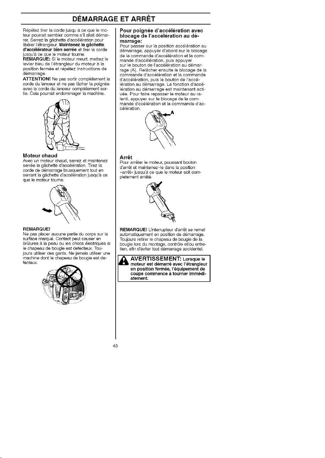
DI_MARRAGE ET ARRET
Repetez tirer la corde jusqu & ce que le mo-
teur pourrait sembier comme s'il aliait demar-
rer. Serrez la gAchette d'acceleration pour
liberer l'etrangteur. Maintenez la g_chette
d'accelerateur bien settee et tirer la corde
jusqu'& ce que le moteur tourne.
REMARQUE: Si le moteur meurt, mettez le
levier bleu de I'etrangleur du moteur a. la
position fermee et repetez instructions de
demarrage.
ATTENTION? Ne pas sortir completement ia
corde du lanceur et ne pas I&cher la poignee
avec ia corde du lanceur completement sor-
tie. Cela pourrait endommager la machine.
Moteur chaud
Avec un moteur chaud, serrez et maintenez
serree la g&chette d'acc61eration. TJrez la
corde de demarrage brusquement tout en
serrant la g&chette d'acceleration jusqu'& ce
que le moteur toume.
Pour poignee d'acceleration avec
blocage de I'acceleration au de-
marrage:
Pour passer sur la position acceleration au
demarrage, appuyer d'abord sur le blocage
de la commande d'acceleration et la com-
mande d'acceleration, puis appuyer
sur le bouton de I'acceleration au demar-
rage (A). Rel&cher ensuite le blocage de ta
commande d'acceleration et la commande
d'acceleration, puis le bouton de I'acce-
leration au demarrage. La fonction d'acce-
leration au demarrage est maintenant acti-
vee. Pour faire repasser le moteur au ra-
lenti, appuyer sur le blocage de la com-
mande d'cceleration et la commande d'ac-
celeration.
Arr6t
Pour arr6ter le moteur, poussant bouton
d'arr6t et maintenez-te dans la position
,,arr6b, jusqu'& ce que le moteur soit com-
31etement arr_t6.
REMARQUE!
Ne pas placer aucune pattie du corps sur la
surface marqu& Contact peut causer en
brOlures & Ia peau ou ies chocs electriques si
le chapeau de bougie est defecteux, Tou-
jours utiliser des gants. Ne jamais utiliser une
machine dont le chapeau de bougie est de-
fecteux.
REMARQUE! L'interrupteur d'arr6t se remet
automatiquement en position de demarrage.
Toujours retirer le chapeau de bougie de la
bougie lors du montage, contr6te et/ou entre-
tien, afin d'eviter tout demarrage accidentel.
AVERTISSEMENT: Lorsque le
moteur est demarre avec retrangleur
en position fermee, requipement de
coupe commence a tourner immedi-
atement,
43

TECHNIQUES DE TRAVAIL
Methodes de travail
IMPORTANT!
Ce section traite des consignes de securite
de base Iors du travail avec un coupe-herbe.
Dans I'eventualite d'une situation rendant la
suite du travail incertaine, consulter un ex-
pert. S'adresser au revendeur eu & I'atelier
de reparation.
Evitez les t&ches pour iesqueiles vous ne
vous sentez pas suffisamment qualifie.
Avant I'utilisation, il est essentiel de com-
prendre la difference entre te deblayage fo-
restier, le debroussailiage et le desherbage.
Regles elementaires de
securite
/hQOO
1. Bien observer la zone de travail:
• S'assurer qu'aucune personne, aucun
animal ou aucun autre faoteur ne ris-
que de g&ner I'utilisateur de la
machine.
• Afin d'eviter que des personnes, des
animaux ou autre n'entrent en contact
avec I'equipement de coupe ou avec
des objets lances par selui-si.
• REMARQUE! Nejamais utiliser une
machine s'il n'est pas possible d'appel-
er au secours en oas d'acoident.
2. Ne pas travailter par mauvais temps:
brouiIlard epais, pluie diluvienne, vent vio-
lent, grand froid, etc. Travailler par mau-
vais temps est cause de fatigue et peut
m6me 6tre dangereux: sol glissant, direc-
tion de chute d'arbre modifiee, etc.
3. S'assurer de pouvoir se tenir et se deplacer
en toute securite. Reperer les eventueis ob-
stacles en cas de deplacement imprevu:
souches, pierres, branchages, fondrieres,
etc. Observer la plus grande prudence Iors
de travail sur des terrains en pente.
L'ABC du deblayage
• Toujours utiliser un equipement adequat.
• Toujours utiliser un equipement correcte-
merit adapte.
• Respecter les consignes de securite.
• Bien organiser le travail.
• Lorsque la lame est appliquee sur le tronc,
toujours faire toumer le moteur & plein re-
gime.
• Toujours utiliser des lames correctement
affOtees.
• Eviter la taille de pierres.
A AVERTISSEMENT: Ni I'utilisa-
teur de la machine, ni qui que ce soit
ne doit essayer de retirer le materiel
vegetal coupe tant que le moteur ou
I'equipement de coupe tourne, sous
peine de blessures graves. Arr6ter le
moteur et I'equipement de coupe
avant de retirer le materiel vegetal
qui s'est enroule autour de raxe de
Is lame, sous peine de blessures.
Apres I'utilisation, le renvoi d'angle
peut 6tre chaud pendant un moment.
Risque de br_lures au contact.
AVERTISSEMENT: Attention
A
aux objets projetes. Toujours utiliser
des protections homologu_,=es pour
les yeux. Ne jamais se pencher au-
dessus de la protection de I'equipe-
ment de coupe. Des cailloux, debris,
etc. peuvent _tre projetes dans les
yeux et causer des blessures tres
graves, voire la cecite. Maintenir
distance toutes les personnes non
concernees par le travail. Les en-
rants, les animaux, les spectateurs et
les collegues de travail devront se
trouver en dehors de la zone de se-
curite, soit a au moins 15 metres (50
pieds). Arr_ter immediatement la ma-
chine si une personne s'approche.
Ne tournez jamais sur vous-m_me
avec la machine sans vous assurer
d'abord que personne ne se trouve
dans la zone de securite.
i_ AVERTISSEMENT: II arrive
des branches ou de I'herbe se coinc-
ent entre la protection et I'equipement
de coupe. Toujours arr_ter le moteur
avant de proceder au nettoyage.
que
4. [_ors des deplasements, arrgter le meteur.
Lors des deptacements longs et des trans-
ports, utiliser le dispositif de protection prevu
& cet effet.
5. Ne jamais placer la machine sur le sol avec
le moteur en marche ou tandis que I'equipe-
ment de coupe toume.
Techniques de travail de base
• Ramener le moteur au regime de ralenti
apres chaque etape de travail. Laisser le
moteur tourner & pleins gaz sans lui faire
subir de charge peut endommager se-
rieusement le moteur.
44

TECHNIQUES DE TRAVAIL
Methodes de travail
liser la plage 12 h - 15 h de la lame,
Du fait de la vitesse de rotation de la
lame, c'est justement sur cette
plage que I'ejection d'objets risque
I& VERTISSEMENT: Eviter d'uti-
de se produire Iorsque la lame est
appliquee sur des troncs plus epais.
• Avant de commencer le deblayage, verifier
le terrain a. debtayer, la nature du terrain,
I'inclinaison du sol, la presence de cailloux,
de fosses, etc.
• Commencer par le c6te du terrain le plus
facile a.deblayer afin d'obtenir une bonne
ouverture de deblayage.
• Travailler systematiquement en allant et en
venant sur le terrain sur une largeur de tra-
vail de 4-5 metres (12-15 pieds). Ainsi, le
rayon d'action total de la machine est utiti-
se, dans les deux sens, et I'utilisateur be-
neficie d'un domaine de travail facile et va-
riable.
• La distance & parcourir dolt 6tre d'environ
75 metres (250 pieds), Deplacer le stock
de carburant en fonction de I'avancement
du travail,
• Si le terrain est en pente, determiner le
parcours de maniere qu'il soit perpendicul-
aire & la pente. II est beaucoup moins fati-
guant de marcher en travers d'une pente,
plut6t que de ta descendre et de ta re-
monter constamment.
• Le parcours dolt 6tre determine de man-
iere a eviter les fosses et autres obstacles
du terrain. Adapter egalement le parcours
en fonction du vent afin que les troncs
deblayes tombent darts la pattie dej& de-
blayee.
Debroussaillage avec une lame &
herbe
QOO
• Ne pas utiliser les tames et les couteaux &
herbe pour les tiges ligneuses,
• La lame a herbe s'utilise pour tousles types
d'herbe haute ou epaisse.
• Faucher I'herbe d'un mouvement de balanci-
er lateral le mouvement de droite a gauche
constituant la fauche et le mouvement de
gauche le retour, Faire travailler la lame du
c6te gauche (secteur 8h a 12 h).
• Si on penche legerement la lame vers la
gauche pendant le debroussaiilage, I'herbe
coupee est disposee en bandes, ce qui faci-
lite le ramassage, par exemple Iors du
ratissage,
• Essayer d'adopter un rythme de travail re-
gulier, Prendre une position stable, les pieds
ecattes, Faire un pas en avant apres le
mouvement de retour et reprendre la
m&me position stable,
• Laisser le bol de garde au sol, Son r61eest
de proteger la tame contre tout contact avec
le sol.
• Respecter les regles suivantes afin d'eviter
que les materiaux ne s'enroulent autour de
la lame:
• Toujours travailler en faisant toumer le mo-
teur a plein regime.
• Eviter de toucher le materiel v6getal cou-
pe au cours du mouvement de retoun
• Arr6ter le moteur, ouvrir le harnais et poser
la machine par terre avant de rassembler le
materiel v6getat coup&
Debroussaillage avec t6te de coupe
Desherbage
• Maintenir ta t6te de coupe juste au-dessus
du sol, I'incliner, Le travail est effectue par
l'extremite du ill, Laisser le fil travailler a son
propre rythme, Ne jamais forcer le fil darts
le materiau a couper.
45

TECHNIQUES DE TRAVAIL
• Le fil facilite _'enlevement d'herbe et de
mauvaises herbes au pied des murs,
cl6tures, arbres et massifs fleuris, mais
il peut aussi endommager I'ecerce des
arbres et des broussailles ainsi que les
poteaux des cl6tures.
• Reduire les risques d'endommager la ve-
getation en limitant la Iongueur du fil & 10-12
cm et en reduisant le regime moteur.
• En desherbage, veus devriez utiliser le mo-
teur toumer & gaz moins de pleine force de
sorte que le fi] de coupe durera p_uslong-
temps et reduirera I'usage sur la t6te de
coupe.
Nettoyage par grattage
• La technique du grattage permet d'entev-
er toute vegetation indesirable. Maintenir
la t&te de desherbage juste au-dessus
du sol, puis i'incliner. Laisser I'extremit6
du fil battre ie soi autour des arbres, po-
teaux, statues et similaires.
REMARQUE! Cette technique accelere
I'usure du ill.
• Le fil s'use plus vite et deit _tre dereule
plus souvent au contact de cailleux, bri-
ques, beton, cl6tures metalliques, ete.
qu'au contact d'arbres et de clStures en
beis.
Coupe
Q00
• Le coupe-herbe est ideal pour atteindre
l'herbe aux endroits difficiiement acces-
sibles avec une tondeuse ordinaire.
Maintenir le fil parailelement au sol Iors
du desherbage. Eviter de presser la t&te
de desherbage centre ie sol, puisque
cela risque d'endommager la pelouse et
le materiel.
• Eviter de maintenir la t6te de desher-
bage constamment au contact avec le
sol en utilisation normale. Un contact
permanent peut endommager ia t6te de
desherbage et accelerer son usure.
Balayage
QOO
• Ueffet soufflant du fii rotatif peut &tre utili-
se pour un nettoyage simple et rapide.
Maintenir le fil parallele et audessus des
surfaces & balayer, puis balader I'outil
suivant un mouvement de balancier.
/
/
\
• Lers de la coupe et du balayage, faire
tourner & plein regime afin d'obtenir un
bon resultat.
AVERTISSEMENT: Ni I'utilisa-
teur de la machine, ni qui que ce soit
ne doit essayer de retirer le materiel
vegetal coupe tant que le moteur ou
la lame tourne, aous peine de blea-
sures graves. Arr6ter le moteur et Is
lame avant de retirer du materiel ve-
getal qui s'est enroule autour de raxe
de Is lame, sous peine de blessures.
Apres rutiliaation, le renvoi d'angle
peut _tre chaud pendant un moment.
Risque de br_lures au contact.
AVERTISSEMENT: Attention
aux objets projetes. Toujours travail-
ler avec des protege-yeux. Ne jamais
se pencher audessus de la protec-
tion de requipement de coupe. Des
cailloux, debris, etc. peuvent _tre
projetes dans les yeux et causer des
blessures tres graves, voire la cecite.
Maintenir a distance toutes les per-
sonnes non concern_,=es per le travail.
Les enfanta, les animaux, les specta-
teurs et les collegues de travail de-
vront ae trouver en dehors de la
zone de aecurite, soit & au moins 15
metres (50 pieds). Arr_ter immedi-
atement la machine si une personne
s'approche.
46

ENTRETIEN
Le proprietaire est responsable d'effectuer tout
i'entretien requis tel qu'indique dans le manuel
d'instructions.
incorrect pourrait provoquer des
dommagss serieux au moteur ou des
[_lk VERTISSEMENT: L'entretien
blessures graves,
Carburateur
Les caracteristiques techniques de cette ma-
chine Jonsered assurent des emissions de
gaz nocifs reduites au minimum. Apres 8-10
pleins, le moteur est rod& Pour s'assurer qu'il
fonctionne de maniere optimale en emetant
aussi peu de gaz nocifs que possible apres la
periode de rodage, il coevient de demander
au revendeur/& I'atelier de reparation (s'il dis-
pose d'un compte-tours) d'effectuer un re-
glage fin du carburateur.
_i AVERTISSEMENT: L'embray-
age complet, couvercle d'embrayage
et raxe de transmission doit 6tre
monte avant de demarrer la machine,
sinon I'embrayage risque de I_cher et
de provoquer des blessurss,
Fonctionnement
• Le carburateur determine ie regime du
moteur via la g&chette de i'acceleration.
C'est darts le carburateur que i'air est me-
lange & I'essence.
• La vis T regle la position de ia g&chette
de I'acceleration au ralenti. Si la vis Test
tournee dans le sees des aiguilles d'une
montre, on obtient un regime de ralenti
plus haut; si erie est tournee dans le sens
contraire des aiguilles d'une montre, on
obtient un regime de ralenti plus bas.
Reglage de base
• Le reglage de base du carburateur est
effectue & I'usine. Le reglage fin doit _tre
effectue par une personne qualifiee.
AVERTISSEMENT: L'equipe-
ment de coupe peut tourner pendant
Iss reglagss de carburateur. Portez
votre equipement de securite et ob-
servez toutss Iss instructions de se-
curit& Soyez s_r de I'arr6ts de I'e-
quipement de coupe quand le mo-
teur tourne au ralenti. Quand I'appe-
reil sst arr_tee, assurez-vous que
I'equipement de coupe s'sst arr_tes
avant de depossr I'appereil au sol.
REMARQUE! Si I'equipement de coupe
tourne au ralenti, tourner ie pointeau de ra-
lenti T dans le sees contraire des aiguilles
jusqu'a I'arr&t de I'equipement de coupe.
REMARQUE! Si I'equipement de coupe
tourne au ralenti, tourner ie poieteau de ra-
lenti T dans le sens contraire des aiguifles
jusqu'& I'arr6t de I'equipement de coupe.
Regime de realenti recommande:
Voir la section "Caracteristiques techniques".
Surregime maxi, recommande:
Voir la section "Caracteristiques techniques".
Reglage final du regime de ralenti-T
Regler le regime de ralenti avec _e pointeau
de ralenti T si un ajustage est necessaire.
Tourner d'abord ie pointeau T dans ie sens
des aiguiiles jusqu'& ce que I'equipement de
coupe commence & tourner. Tourner ee-
suite le pointeau dans le sens inverse jus-
qu'& I'arr&t de i'6quipement de coupe. Un
regime de ralenti correctement regle permet
au moteur de toureer regulierement dans
toutes les positions. II doit egalement y
avoir une bonne marge avant que I'equipe-
meet de coupe se mette & tourner.
,:__ Vis de r_,glage
au ralentl
AVERTISSEMENT: Sll est
impossible de regler le regime de
ralenti de maniere a immobilissr
I'equipement de coupe, contacter le
revendeur ou I'atelier de reperation.
Ne pes utilissr la machine tant qu'e-
lie West pas correctement reglee ou
reperee.
Securite de rappareil et dans
le entretien
Debranchez toujours le fil de la bougie
quand vous ferez des reparations, saif les
reglages de caburateur.
Silencieux
REMARQUE? Votre silencieux est equipe
d'un pot catalytique con cu pour reduire la
teneur des gaz d'echappement en sub-
stances toxiques.
\:'_\ )
"4-.
47
/

ENTRETIEN
Le silencieux est con cu pour reduire au
maximum le niveau soeore et detourner les
gaz d'echappement loin de I'utifisateur. Le
silencieux est con cu pour attenuer ]e bruit et
devier le flux des gaz d'echappement loin de
l'utilisateur.
Ces gaz sont chauds et peuvent transporter
des etincelles risquant de causer un incendie
si e]les entrent en contact avec un matefiau
sec et inflammable.
Votre silencieux sont munis d'une grille pare-
etince_les. La grille devrait 6ire vefifiee et, au
besoin, nettoyee par un distfibuteur autofis&
Si la grille est endommagee, elle devrait
6tre remplacee, Si la grille est souvent bou-
chee, ceci peut 6tre dQ & un mauvais fonc-
tionnement du pot catalytique. Contacter le
revendeur pour effectuer un contrSle. Une
grille antiflamme bouchee provoque la sur-
chauffe de la machine et la deterioration du
cyIindre et du piston.
de silencieux
Grille pare-_,tiecelles
REMARQUE! Ne jamais utiliser la machine
si le silencieux est en mauvais etat,
l_i AVERTISSEMENT: un silen-
cieux muni d'un pot catalytique est
tres chaud aussi bien & I'utilisation
qu'apres arr6t. Ceci est egalement
vrai pour le regime au ralenti. Tout
contact pout causer des brQlures a la
peau. Attention au risque d'incendie!
Bougie
Uetat de la bougie depend de:
• Uexactitude du reglage du carburateur.
• Mauvais melange de i'huile daes ie car-
burant (trop d'huiie ou huile inappropriee).
• La proprete du filtre & air.
Ces facteurs peuvent concourir & I'apparition
de calamine sur les electrodes, ce qui & son
tour entratne un mauvais fonctionnement du
moteur et des demarrages difficiles.
Si ia puissance de la machine est trop faib]e,
si ia machine est difficile & mettre en marche
ou si ie ralenti est irregulier, toujours com-
mencer par contr61er I'etat de la bougie avant
de prendre d'autres mesures. Si la bougie est
encrassee, ia nettoyer et verifier que I'ecarte-
ment des electrodes est de 0,6 mm (0,024
pouce). Remplacer ia bougie une fois par
mois ou plus souvent si n_,cessaire.
REMARQUE] Toujours utiliser le type de
bougie recommande! Une bougie incorrecte
peut endommager le piston/le cylindre.
0,6 mm (0,024 pouce)
Filtre a air
du silencieux contient des produits I
chimiques pouvant _tre cancerigenes, I
_IkAVERTISSEMENT: L'interieur I
Eviter tout contact avec ces elements
si e si encieux est endommag&
_1 AVERTISSEMENT: N'oubliez
pas que:
Les gaz d'echappement du moteur
contiennent de roxyde de carbone
pouvant provoquer rintoxication.
Ne jamais demarrer ou utiliser la ma-
chine a I'interieur d'un b_timent ou
dans un lieu real aer& Les gaz d'e-
chappement du moteur sont tres
chauds et peuvent contenir des etin-
celles pouvant provoquer un incendie.
Par consequent, ne jamais demarrer
la machine darts un local clos ou
proximite de materiaux inflammables!
Le filtre & air doit _tre maintenu propre pour
_,viter:
• Un mauvais fonctionnement du carburateur
• Des problemes de demarrage
• Une perte de puissance
• Une usure prematuree des el_,ments du
moteur
• Une consommation anormalement elevee
de carburant
j/f
Nettoyer le fiitre apres 25 heures de service,
ou ptus souvent si les conditions de travail
sont exceptionnellement poussiereuses.
48

ENTRETIEN
Nettoyage du filtre a air
Deposer le capet de filtre et retirer le filtre.
Nettoyer le filtre avec de i'eau chaude sa-
vonneuse. Rincage compietement. S'as-
surer que le fiitre est sec avant de le re-
monter. Un filtre ayant servi Iongtemps ne
peut plus _tre comp_etement nettoye. Le
filtre & air doit donc 6tre remplace & inter-
valles reguliers. Tout filtre endommage
dolt 6tre remplace immediatement,
Renvoi d'angle
Le renvoi d'angie est enduit en usine de la
quantite de graisse necessaire. Toutefois,
avant d'utiliser la machine, il convient
de s'assurer que le renvoi d'angle est au
3/4 rempli de graisse. Utiliser une graisse
JONSERED speciale.
En general, il n'est pas necessaire de rem-
placer ie lubrifiant du carter, sauf en cas de
reparations.
Afft_tage des lames et couteaux
herbe
AVERTISSEMENT: Toujours
&
arr_ter le moteur avant d'entamer
des travaux sur I'equipement de
coupe. Celui-ci continue de tourner
apres qu'on a rel_che raccelerateur.
S'asaurer que requipement de
coupe sat completement immobilise
et debrancher le c&ble de la bougie
d'allumage avant de commencer I'in-
tervention sur r_,quipement
de coupe.
•Voir les instructions d'aff_tage sur I'em-
bailage de I'equipement de coupe.
• Les lames et couteaux s'affOtent & I'aide
d'une lime plate & tailie simple.
• Limer les tranchants de maniere egale
afie de preserver I'equilibre.
AVERTISSEMENT: Toujours
une lame pliee, fausaee, fisau-
ree, casaee ou abimee de toute autre
fagon, Ne jamais essayer de redress-
er une lame faussee pour I'utilisar de
nouveau. Utilisar uniquement des
lames d'origine du modele recom-
mande.
49

ENTRETIEN
Schema d'entretien
La liste ci-dessous indique I'entretien a.effectuer sur la machine. La plupart des points sont
decrits & la section Entretien. L'utilisateur ne peut effectuer que les travaux d'entretien et de
revision decrits darts ce manuel d'utilisation. Les mesures plus importantes doivent 6tre
effectuees dans un atelier d'entretien aqre&
Entretien quotidien hebdomadiare mensuel
Nettoyer Fexterieur de la machine. X
Contr61er le ben fonctionnement du verrou
d'accelerateur et de I'accelerateur. X
ContrSler le ben fonctioneement du contac-
teur d'arr6t. X
S'assurer que I'equipement de coupe ne
toume pas Iorsque le moteur toume au ralenti. X
Nettoyer le filtre a.air. Le remplacer si
necessaire. X
S'assurer que la protection est intacte et
qu'elle ne presente pas de fissures. Rem-
placer la protection si elle a subi des coups
ou si elle preseete des fissures. X
S'assurer que la t6te de desherbage est
intacte et qu'elle n'est pas fissuree. Au be-
soin, remplacer la t6te de desherbage. X
Contr61er que le contre-ecrou de I'equipe-
ment de coupe est serre correctement. X
S'assurer que routes les vis et tousles
ecrous sont bien serres. X
Verifier qu'il n'y a pas de fuite de carburant
du moteur, du reservoir ou des
conduits de carburant. X
ContrSler le demarreur et son lanceur. X
Nettoyer la bougie d'allumage exterieure-
ment. Deposer la bougie et verifier la dis-
tance entre les electrodes. Au besoin, ajus-
ter la distance de sorte qu'elle soit de 0,6
mm, ou remplacer ta bougie. S'assurer que
la bougie est dotee d'un antiparasites. X
Nettoyer le carburateur exterieurement, aim
si que I'espace autour. X
Verifier que le renvoi d'angle est au 3/4
rempli de graisse. Au besoin, faire un rem-
pHssage d'appoint avec une graisse spe-
ciale. X
ContrSler que le filtre a.carburant n'est pas
contamine ou que le tuyau de carburant ne
comporte pas de fissures ou d'autres ava-
des. Remplacer si necessaire. X
Inspecter tous les c&bles et coenexions. X
Verifier I'etat d'usure de I'embrayage, des
ressorts d'embrayage et du tambour d'em-
brayage. Faire remplacer si necessaire
dans un atelier d'entretien agre& X
Remplacer la bougie d'allumage. S'assurer
que la bougie est dotee d'un antiparasites. X
ContrSler et nettoyer la grille antiflamme du
silencieux. X
Entretien Entretien Entretien
5O

CARACTI_RISTIQUES TECHNIQUES
Caracteristiques techniques
Moteur
Cylindree, cm3 28
Alesage, mm 35,0
Course, mm 38,7
Regime de ralenti, tr/min 2800-3200
Regime d'emballement maximal recommande, tr/min 10000
Regime de Faxe sortant, tr/min 8000
Puissance moteur maxi selon ISO 8893, hp/kW 1,1/0,8
Silencieux avec pot catalytique Oui
Systeme d'aflumage regle en fonction du regime Oui
Systeme d'allurnage
Fabricant/type de systeme d'allumage
Bougie
Ecartement de electrodes, mm
Carburant, systerne de graissage
Fabricant/type de carbureteur Zama
Contenance du reservoir de carburant, litres 0,4
Poids
Poids, sans carburant, equipemeet de coupe et
dispositifs de securite, kg 4,8
Niveaux sonores
(voir Remarque 1)
Pression acoustique equivalente au niveau des oreilles
de l'utilisateur, mesuree selon ANSI B175.3-1997, dB(A),
min/max: 94/97
Niveaux de vibrations
Niveau de vibrations au niveau des poignees, mesuree
selon ANSI B175.3-1997, m/s 2
,Au ralenti, poignee gauche/droite: 3/5
A plein regime, poignee gauche/droite: 9/8
Remarque 1: le niveau de pression acoustique equivalent correspond & ia somme d'eeer-
gie ponderee en fonctioe du temps pour les niveaux de pression acoustique & differents
regimes pendant les durees suivantes: 1/2 ralenti et t/2 plein regime.
REMARQUE! Le niveau de pression acoustique & I'oreille de I'utilisateur et les vibrations
dans les poignees sont mesures avec tous les equipements de coupe agrees de la
machine. Les valeurs les plus hautes et les plus basses sont indiquees dans le tableau.
BC 2126
Walbro/CD
Champion RCJ-8Y
0,6
Modele BC 2126 (Axe de filete M1O L) - Trou central des lames/couteaux O 25,4 mm
Accessoires homologues Type coups, numero de la piece
Lame/couteau & herbe Grass 255-4 1 pouce 503 93 42-02
(O 255 4 dents)
T&te de coupe T25 537 33 83-02
Couteaux en plastique Tricut 300 mm 531 00 38-11
Bol de garde au sol Fixe
51
Protectuer pour equipement de,

DECLARATION DE GARANTIE DE LUTTE AN MISSIONS
U.S. EPA / CALIFORNIE / ENVIRONNEMENT CANADA
DROITS ET OBLIGATIONS DE
VOTRE GARANTIE:
La U. S. Environmental Protection Agency,
Environnement Canada et Jonsered ont le
piaisir d'expfiquer la garantie du systeme de
contr61e des emissions sur votre petit mo-
teur tout-terrain, pour les annees 2005 et
plus tard. Jonsered dolt garantir ie systeme
de contr61e des emissions de votre petit
moteur tout-terrain pendant la periode indi-
quee ci-dessous, a.condition qu'il n'y ait eu
aucun mauvais traitement, negligence ou
mauvais entretien du petit moteur tout-ter-
rain. Votre systeme de contr61e des emis-
sions comprend des pieces comme le car-
burateur et le systeme d'aliumage. S'il se
produit une panne couverte par la garantie,
Jonsered reparera votre petit moteur tout-
terrain gratuitement pour vous. Les frais
couvertes par ia garantie eomprennent le
diagnostic, les pieces et la main-d'oeuvre.
COUVERTURE DE GARANTIE DU
FABRICANT :
Si une piece relative aux emissions de
votre moteur (figurant sur la liste de pieces
garanties & titre du contr61e des emissions)
est defectueuse ou si un vice de materiau
ou de main-d'oeuvre du moteur occasionne
la panne d'une piece relative aux emis-
sions, cette piece sera changee ou repar6e
par Jonsered.
RESPONSABILITES DE GARANTIE
DU PROPRII_TAIRE :
En quaiite de proprietaire du petit moteur
tout-terrain, vous &tes responsable d'effec-
tuer I'entretien requis tel qu'indique darts
votre manuel d'instructions, mais Jonsered
ne peut annuler votre garantie uniquement
parse que vous n'avez pas conserve vos
re9us ou parce que vous n'avez pas effec-
tue tout I'entretien prevu. En qualite de pro-
prietaire du petit moteur tout-terrain, vous
devez realiser que Jonsered peut vous re-
fuser de couvrir votre garantie si votre petit
moteur tout-terrain ou une piece de ce mo-
teur tombe en panne & la suite d'un mau-
vais traitement, de negligence, de mauvais
entretien, de modifications non approuvees
ou & la suite de I'utilisation de pieces qui ne
sont pas faites ou approuvees par le fabri-
cant de materiel original Vous 6tes re-
sponsable de presenter votre petit moteur
tout-terrain & un distributeur autorise de
service de Jonsered aussit6t que se pre-
sente un probleme. Les reparations couv-
ertes par cette garantie doivent &tre termi-
nees darts des delais raisonnables, ne pou-
vant pas depasser 30 jours.
Si vous avez des questions sur vos droits
et vos responsabilites en vertu de la garan-
tie, vous pouvez contacter votre distributeur
autorise de service le plus proche ou appel-
er Jonsered au numero t-916-383-3511.
DATE DE DC_BUT DE GARANTIE :
La periode de garantie commence _tla date
& laquelle vous avez achete votre petit mo-
teur tout-terrain.
DURI_E DE COUVERTURE :
Cette garantie est va_able pendant deux
arts & partir de la date d'achat initial.
CE QUI EST COUVERT : RI_PARA-
TION OU REMPLACEMENT DES
PARTIES.
La reparation ou le remplacement de toute
piece sous garantie sera effectuee gratuite-
ment pour ie proprietaire de I'appareil darts
un distributeur autorise de service Jons-
ered. Si vous avez des questions sur vos
droits et vos responsabilites relativement &
cette garantie, vous devez contacter votre
distributeur autorise de service le plus pro-
che ou appeler Jonsered au numero
1-916-383-3511.
PC_RIODE DE GARANTIE:
Toute piece sous garantie qui ne doit pas
@tre remplacee pour un entretien normal, ou
qui doit seulement @tre inspectee reguliere-
ment pour voir s'il faut la reparer ou la rem-
placer, est garantie pendant deux ans.
Toute piece qui dolt @tre remplac@e pour un
entretien normal est garantie jusqu'& la date
de premier remplacement prevu.
DIAGNOSTIC :
Le proprietaire ne dolt pas payer la main-
d'oeuvre pour le diagnostic & I'aide duquel
on a determin@ qu'une piece sous garantie
est defectueuse si le travail de diagnostic a
ete effectue dans un distributeur de service
Jonsered.
DOMMAGES INDIRECTS :
Jonsered peuvent _tre responsables de
dommages & d'autres elements de moteur
occasionnes par la panne d'une piece sous
garantie.
CE QUI N'EST PAS COUVERT :
Toute panne occasionnee par un mauvais
traitement, la negligence ou un mauvais en-
tretien n'est pas couverte.
PI#CES AJOUTI_ES OU MODIFIEES :
Uutilisation de pieces ajoutees ou modifiees
peut constituer une raison d'annulation de
reclamation en vertu de la garantie. Jons-
ered n'est pas responsable de couvrir ies
pannes de pieces sous garantie occasion-
nees par i'utilisation de pieces ajoutees ou
modifiees.
52

DECLARATION DE GARANTIE DE LUTTE AN MISSIONS
U.S. EPA / CALIFORNIE / ENVIRONNEMENT CANADA
COMMENT REMPLIR UNE RE-
CLAMATION :
Si vous avez des questions sur yes droits
et vos responsabilites de garaetie, vous
pouvez contacter votre distributeur autorise
de service le plus proche ou appeler Jons-
ered au numero 1-916-383-35tl.
O00BTENIR LE SERVICE EN VER-
TU DE LA GARANTIE :
Le service ou _es reparatioes en vertu de la
garantie sont offerts darts tousles distribu-
teurs autorise de service Jonsered. Appe-
lez le numero 1-916-383-3511.
ENTRETIEN, REMPL.ACEMENT OU
REPARATIO N DE PIECES REL-
ATIVES A L'EMISSION :
Toute piece de remplacement approuvee
Jonsered uti_isee daes I'accomplissement
de tout entretien ou reparation en vertu de
la garantie sur les pieces relatives a 1'6mis-
sion sera foureie gratuitement au propriet-
aire si cette piece est sous garantie.
Ce moteur est certifie se conformer aux regles d'emissions pour les usages suivants :
[] Modere (60 heures)
[] Intermediaire (125 heures)
[] Etendu (300 heures)
LISTE DES PIECES GARANTIES
RELATIVES AU CONTROLE DES
EMISSIONS :
• Carburateur
• Systeme d'altumage: bougie (couverte jus-
qu'a ta date de remplacement pour I'entre-
tien), module d'allumage
• Silencieux avec d'un pot catalytique
DleCLARATION D'ENTRETIEN :
Le proprietaire est responsabte d'effectuer
tout I'entretien requis tel qu'indique dans le
manuel d'iestructions.
53

Remplacement du fil dans la t_te de coupe _
4
20'
8
"Click"
54

Couteaux
1
6
5
7 _ 6Nm
55

ACLARACION DE LOS SIMBOLOS
Simbolos
ADVERTENCIA: Las desbrozado-
ras, quita arbustos y recortaderas ,_,
pueden ser peligrosas! Su use /l_
descuidado o erroneo puede / _
provocar heridas graves o
mortales ai usuario o terceros.
Lea detenidamente el manual de
instrucciones y asegOrese de en- r[l[h
tender su contenido antes de
utiIizarla maquina.
Utilice siempre:
• Casco protector cuando exista
el riesgo de objetos que caen
• Protectores auriculares
•Proteccion ocular homologada
Velocidad maxima en el eje de
saiida, rpm
Q
m_x
10000 rprn
/k
Cuidado con los objetos lanzados J_,_'_.
o rebotados.
Durante el trabajo, el usuario _, ,.,-'_-"_
de ia mAquina debe procurar
que ninguna persona o animal
se acerque a mAs de 15 metros
(50 pies) a la mAquina.
Las maquinas equipadas con hoja
de sierra o para hierba pueden ser
lanzadas violentamente hacia
el costado cuaedo la hoja _ /_
entra en contacto con objetos
flies. La hoja puede causar la
amputaci6n de brazos y
piernas. Mantenga siempre a
terceros y animales alejados de la
maquina, a 15 metros (50 pies)
come minimo.
Marcas de flechas que indican
los limites para coiocar ia
sujeci6n del mango.
Utilice siempre guantes protec-
totes homologados.
Utilice gasolina sin ptomo o de
gran calidad y aceite para
motores de dos tiempos
mezclado en proporcional
2% (t :50).
Los demas sJmbolos/etiquetas que apa-
recen en la maquina cotresponden a re-
quisitos de homologacion especJficos en
deterrninados rnercados.
Para detener el motor, empuje
y sostenga el interruptor stop
en la posici6n STOP. iNOTA!
El interruptor retorna automAtica-
mente a la posici6n de arranque.
Por consiguiente, antes de realizar [_J
trabajos de montaje, control y/o
mantenimiento se debe quitar
el capuchon de encendido de ta
bujia para evitar el arranque
imprevisto, hasta que eI motor
se haya detenido por completo
antes de hacer cualquier
mantenimiento.
regularmente.
La mAquina debe limpiarse
Control visual. ['_
Debe utiiizarse proteccion ocularhomologada.
%
Utilice botas antideslizantes y
seguras.
Indicado Linicamente para equipo
de corte flexible, no metAlico, es
decir cabezal de corte con linea
d¢_r_nrf_
56

CONTENIDO
indice
ACLARACION DE LOS SiMBOLOS
Simbolos ........................ 56
iNDICE
indice ........................... 57
Antes de arrancar, observe Io siguiente: 57
6aUE ES QUE?
&Que es que? .................... 58
INSTRUCCIONES GENERALES
DE SEGURIDAD
Importante ....................... 59
Equipo de protecci6n personal ...... 59
Equipo de seguridad de la maquina .. 60
Equipo de corte ................... 62
MONTAJE
Moetaje det maniltar ............... 64
Montaje del arnes y la abrazadera ... 64
Montaje de la hoja y del cabezal
de corte ......................... 65
Montaje de la protecci6n de hoja, hoja
de hierba y cuchilla de hierba ....... 65
Montaje de la protector y la
cabezal de corte .................. 66
MANIPULACION DEL COMBUSTIBLE
Seguridad en el use del combustible . 67
Carburante ...................... 67
Repostaje ....................... 68
ARRANQUE Y PARADA
Control antes de arrancar .......... 69
Arranque y parada ................ 69
TI_CNICA DE TRABAJO
Instrucciones generales de trabajo... 71
MAINTENIMIENTO
Carburador ...................... 74
Silenciador ....................... 74
Bujia ............................ 75
Filtro de aire ..................... 75
Engranaje angulado ............... 76
Afilado de la cuchilla y la hoja para
hierba ........................... 76
Programa de mantenimiento ........ 77
DATOS TECNICOS
Dates teceicos ................... 78
DECLARACION DE GARANTIA DE
CONTROL DE EMISlON .......... 79
Antes de arrancar, observe Io
siguiente:
Lea detenidamente el manual de h_struc-
clones. El mantenimiento, el reemplazo, o la
reparacion de los dispositivos del control de
emisi6n y el sistema se pueden realizar per
cuatquier establecimiento o individuo de la
reparaci6n det motor para uso fuera de car-
retera. Jonsered trabaja constantemente para
perfeccionar sus productos y se reserva, per
Io tanto, el derecho a introducir modifica-
clones en la construcci6n y el dise[_o sin pre-
vio aviso.
prolongadc al ruido puede ccuscr
dafioc cronicoc en el oido. Use
ciempre protectores curiculares
ADVERTENCIA: Laexposicion J
homologados.
El periodo de conformidad de las emisiones
referido en la etiqueta de las emisiones indica
el n0mero de las horas de funcionamiento
9ara las cuales el motor se ha comprovado
9ara satisfacer requisitos federales de las
emisiones. Categoria C = 50 horas, B = 125
horas, y A = 300 horas.
iADVERTENCIA!
Losgasesdeescapedelmotordeesteproducto
contienensustanciasqtfmicasconocidasenel
Estadode Californiacomocausantesdec_cer,
defectos cong_nitos y otms dafios reproductivos.
Para la referencia por favor, complete la
informacion siguiente que cea necesa-
ria para el mantenimiento future de cu
aparato:
NOmero de modelo:
NOmero de serie:
Fecha de la compra:
Distribuidor:
ADVERTENCIA: una desbroza-
dora, quita arbustoc o recortadora
puede ser una herramienta peligro-
ca ci ce utiliza de manera erronea o
descuidada, y provocar heridac
graves o mortalec al ucuario o ter=
ceros. Es sumamente importante
que lea y comprenda el contenido
de este manual de inctruccionec.
ADVERTENCIA: Bajo ningu-
na circunctancia debe modifi-
carse la configuracion original
de la m&quina sin autorizacion
del fabricante. Utilizar ciempre re-
cambioc originalec. Las modifica-
clones y/o la utilizacion de acce-
sorios no autorizadac pueden
ocacionar accidentec graves o
incluso la muerte del operador o
de terceroc. Su garantia puede no
cubrir el dafio causada por el uco
de accecorioc o de piezac de re-
cambio que no se recomiendan.
57

©®
QUE ESQUE?
@
@
@
i.,Qu(_ es qu(_?
1. Cuchil_a
2. Recarga de lubricante,
engranaje angulado
3. Engranaje angulado
4. Protector
5. Eje
6. Manil_ar
7. Acelerador
8. Interruptor stop
9. Fiador del ace_erador
10. Abrazadera de1 arnes
11. Cubierta del ciliedro
12. Starter handle
13. Dep6sito de combustible
14. Estrangulador
15. Bomba de combustible
16. Cubierta de_ filtro de aire
17. Regulaci6n de manillar
18. Contratuerca
19. Brida de apoyo
20. Cazoleta de apoyo
21. Pieza de arrastre
22. Cabezal de corte
23. Llave de la tuerca de cuohilla
24. Protecci6n para transportes
25. Llave hexagonal
26. Pasador de seguridad
27. Ames
28. Boton de aceleraci6n de arraeque
29. Ajuste de1 cable de1 acelerador
30. Manual de instrucciones
58

INSTRUCCIONES GENERALES DE SEGURIDAD
Importante
IMPORTANTE!
La maquina esta destinada exclusivamente a
recortar la hierb&
Los Qnicos accesorios que Ud. puede aco-
_laral motor como fuente propulsora son los
equipos de corte que nosotros recomenda-
mos en el capitulo Datos tecnicos.
Nunca utilice la m_tquina si est'. cansado, si
ha ingerido alcohol o si toma medicamentos
que puedan afectarte la vista, su capacidad
de discernimiento o el control del cuerpo.
Nunca utilice la m_.quina en condiciones at-
mosfericas extremas como frio intenso o clF
ma muy caluroso y/o hL_medo.
Utilice el equipo de protecci6n personal. Vea
las instrucciones bajo el titulo Equipo de pro-
teccion personal.
No utilice nunca una maquina que haya sido
modificada de modo que ya no coincida con
la configuraci6n original
No utilice nunca una maquina defectuosa.
Siga las instrucciones de mantenimiento,
control y servicio de este manual Algunas
medidas de mantenimiento y servicio deben
ser efectuadas per especialistas formados y
cualificados. Yea las instrucciones bajo el
titulo Mantenimiento.
Todas las cubiertas y protecciones deben
estar moetadas antes del arranque. Controle
que la capsula y el cable de encendido esten
en buenas condiciones. Pueden producirse
descargas electricas.
El usuario de la m#.quina debe asegurarse
de que ninguna persona o animal se acer-
quen mas de 15 metros (50 pies) durante el
trabajo. $i varios usuarios trabajan en el mis-
mo lugar, la distancia de seguridad debe ser
15 metros (50 pies).
Equipo de protecci6n personal
IMPORTANTE! Una desbrozadora, quita
arbustos o recortadora puede ser una her-
ramienta peligrosa si se utiliza de manera
err6nea o descuidada, y provocar heridas
graves o mortales al usuario o teroeros.
Es sumamente importante que lea y com-
_renda el contenido de este manual de
instrucciones.
Para trabajar con la maquina debe utili-
zarse un equipo de protecci6n personal
homologado. El equipo de proteccion per-
sonal no elimina el riesgo de lesiones,
pero reduce su efecto en caso de acci-
dente. Pida a su distribuidor que le
asesore en la elecci6n det equipo.
ADVERTENCIA: Cuando use
proteccion auditivapreate siempre
atencion a laa aehales o Ilamados
de advertencia. Saqueae aiempre
la proteccion auditiva inmediata-
mente despues de parar el motor.
CASCO
Es obligatorio usar casco si van a desbro-
zarse ramas a una altura superior a 2 metros
PROTECCION AUDITIVA
$e debe utilizar protecci6n auditiva con su-
ficiente capacidad de reducci6n sonora.
corte defectuoso o una hoja real aft-
lada pueden aumentar el riesgo de
[_ DVERTENOIA: un equipo de
aecidentes.
_i ADVERTENCIA: Nopermita
nunca que los ni_os utilicen la
maquina ni permanezcan cerca de
ella. Dado que la maquina tiene un
contacto de parada con retorno por
muelle ye puede arrancar con poca
velocidad y fuerza en la empu_adu-
ra de arranque, incluso nifma pe-
quehos pueden, en determinadaa
circunstancias, Iograr la fuerza ne-
cesaria para arrancar la maquina.
EIIo puede comportar riesgo de
da_os peraonalea graves.
Pot consiguiente, saque el ca-
puch6n de encendido cuando va a
dejar la maquina sin vigilar.
PROTECCION OCULAR
Se debe utilizar siempre protecci6n ocular
homologada. Si se utitiza visor, deben utili-
zarse tambien gafas protectoras homologa-
das. Per gafas protectoras homologadas se
entienden tas que cumpten con la norma
ANSI Z87.1.
GUANTES
$e deben utilizar guantes cuando sea
necesado, per ejemplo al montar el equipo
de co_te.
5g

INSTRUCCIONES GENERALES DE SEGURIDAD
BOTAS
Utilice botas antideslizantes y seguras.
VESTIMENTA
Use ropas de material resistente a los des-
garros y no demasiado amptias para evitar
que se enganohen ee ramas, etc. Use
siempre pantalones largos gruesos, No tra-
baje con joyas, pantalones cortos, sandalias
ni los pies descalzos. No Ileve el cabello
suelto por debajo de los hombros.
EQUlPO DE PRIMEROS AUXlLIOS
Tenga siempre a mano el equipo de prim-
eros auxitios.
Ecluipo de seguridad de la
maqu,na
En la secci6n se descdben los componentes
de seguridad de la ma.qu}na, su funci6n y el
modo de efectuar e_control y e_maetenimien-
to para garantizar un funcionamieeto 6ptimo.
En cuanto a la ubicaci6n de estos compo-
nentes en su m#.quina, yea la secci6n "Con-
ozca su aparato". La vida Qtil de la mAquina
puede acortarse y el riesgo de accidentes
puede aumentar si el manteeimiento de la
mAquina no se hace de forma adecuada y si
los trabajos de servicio y/o reparaci6n no se
efectSan de forma profesional. Para m_.s }e-
formaci6n, consulte con el distribuidor autori-
zado del servicio mAs cercano.
ilMPORTANTE! Todos los trabajos de
servicio y reparaci6n de la mAquiea re-
quieren una formaci6n especial. Esto es
especiaimente importante para el equipo
de seguridad de la m&.quina, Si la maquina
no pasa alguno de los controles indicados
a continuacion, acuda a su taller de servi-
cio local. La compra de algueo de nues-
tros productos le garantiza que puede re-
cibir un mantenimiento y servicio profe-
sionaL Si no ha adquirido la maquina en
una de nuestras tiendas especializadas
con servicio, solicite informaci6n sobre el
taller de servicio m&.s cercano.
una rnaquina con componentes de
seguridad defectuosos, Siga las
instrucciones de control, rnantenimi-
_ ADVERTENCIA: Nunca utilice
ento.y, servicio indicadas en este
section.
Fiador del acelerador
El fiador del acelerador est'. disefiado para
impedir la activaci6n involuntaria del aceF
erador. Cuando se oprime el fiador (A) en
el mango (= ouando se agarra el mango),
se desaoopta el acelerador (B). Cuando se
suelta el mango, el acelerador y el fiador
vuelven a sus posiciones originales. Am-
bas funciones se efectOan con sistemas
independientes de muelles de retorno, Con
esta posicion, al acelerador queda au-
tom&.ticamente bloqueado en ralenti.
Compruebe que el aeelerador este blo-
queado en la posicion de ralenti cuando el
fiador est&. en su posicion inicial.
Apriete el fiador del acelerador y com-
pruebe que vuelva a su posici6n de
partida al soltarlo_
Compruebe que el acelerador y el fiador se
muevan con facilidad y que funcionen sus
muelles de retorno. /_
Consulte las instrucciones bajo el titulo Ar-
ranque. Ponga en marcha la maquiea y
acelere al maximo. Suelte el acelerador y
controte que el equipo de corte se detenga
y permanezca inm6vE Si el equipo de corte
gira con el acelerador en ralenti, se debe
controtar la regulaci6n del carburador para
ralentL Consulte las instrucciones bajo el
titulo Mantenimiento.
60
//

INSTRUCCIONES GENERALES DE SEGURIDAD
ADVERTENCIA: Ls sobre ex-
posicion a las vibraeiones puede
producir leaionea vasculares o ner-
viosss en personas que padecen
de traatornoa circulatorioa. Si ad-
vierte sintomas que puedan rela-
cionarse con la sobreexposici6n a
laa vibraciones, eonsulte a un me-
dico. Ejemplos de estoa sintomas
son entumecimiento, falta de sen-
Parada
Arranque el motor y asegLirese que el se
haya detenido por completo cuando usted
empuja y sostenga el interruptor STOP.
Protector del equipo de corte
Esta protector tiene por fin evitar que el
usuario reciba el impacto de objetos des-
prendidos. La protector evita tambien que
el usuario entre en contacto con el equipo
de corte.
sibilidad, "hormigueo", "punta-
das", dolor, perdida o reduction de
la fuerza normal, cambioa en el
color o Is superfieie de la piel. Gen-
eralmente, estos sintomaa se pres-
entan en los dedos, las manoa y
las muftecas. El rieago puede ser
mayor a bajas temperaturas.
Desprendimiento de emergencia
En la parte delantera hay un desprendi-
miento de emergencia de facil acceso
como medida de seguridad en caso de que
haya una situaci6n en que sea necesario
liberarse de la m#tquiea y el arnes. Con-
suite las instrucciones bajo el titulo Regu-
laci6n del arnes.
©antrole que las correas del arnes estfn
correctamente colocadas. ©uando el arnes
y la mfquina estfn regulados, controle que
funcione el desprendimiento de emergen-
cia del arnes.
Silenciador
Controle que la protecci6n no este daifiada y
que no tenga grietas. Cambie ta proteccion
si ha estado expuesta a golpes o si tiene
grietas. Utilice siempre la protecci6n recom-
endada para cada equipo de corte en partic-
ular. Consulte e1cap{tulo Datos tecnicos.
circunstancia se puede utilizar un
equipo de corte sin haber montado
antes la proteccion recomendada.
Conaultar el capitulo Datos tecnicos.
Si ae monta una proteccion incor-
I_ DVERTENCIA: Bajo ninguna
recta o defectuosa, esto puede cau-
sar dafms personales graves.
El usa de un bobina mal enroscado o del
equipo de corte incorrecto aumenta el nivel
de vibraciones.
El silenciador estfi dise_ado para reducir al
maximo posible el nivel sonoro y para
apartar Iosga_es de escape del usuario.
PRECAUCION: El silenoiador con
catalizador esta deseSado para reducir
las sustancias nocivas en los gases de
escape.
El silenciador en este aparato incorporan una
rejilla apagachispas. El rejiJla debe ser com-
probado yen caso de necesidad, limpiar por
una distribuidor autorizado del servicio. Si et
rejilla se obstruye, la maquina se recalienta y
produce daifios serios. No utilice nunca un
silenciador con el rejilla apagachispas daSa-
do. Vea la secci6n Mantenimiento.
61

INSTRUCCIONES GENERALES DE SEGURIDAD
Tornillos del
silenciador
Rejilla
apagachispas
Para el silenciador, es sumamente impor-
tante seguir las instrucciones de control,
mantenimiento y servicio. Nunca utilice
una m#.quina que tenga un silenciador
defectuoso.
Compruebe regularmeete que el sileeciador
este firmemente montado en la maquina,
ADVERTENCIA: El silenciador
con catalizador se calienta mucho
durante el uso y permanece caliente
a_n luego de apagado el motor. Lo
mismo rige para la marcha en ra-
lenti. Su contacto puede quemar la
piel. iTenga en cuenta el peligro de
incendio!
ADVERTENCIA: En el interior
del silenciador hay sustancias
quimicas que pueden ser cancerige-
has. Evitar el contacto con estas
sustancias si se daha el silenciador.
ADVERTENCIA: Recuerde que:
Los gases del motor contienen
monoxido de carbono que puede
provocar intoxicacion. Por eso, nun-
ca arranque ni haga funcionar la
maquina en ambientes cerrados, o
cuando no exista una buena circula-
cion de aire. Los gases de escape
del motor estan calientes y pueden
contener chispas que pueden provo-
car incendio. Por esa razon, inunca
arranque la maquina en interiores o
cerca de material inflamable!
Contratuerca
Para fijar determinados equipos de corte
se utiliza una contratuerca,
Para el montaje, apriete la tuerca gir_.edola
en sentido contrario ai sentido de rotaci6n
de1 equipo de corte. Para el desmontaje,
afioje la tuerca gir_.ndola en el sentido de
rotaci6n de1 equipo de corte. (NOTA: La
tuerca tiene rosca a izquierdas.) Apriete la
tuerca con la Ilave tubular.
El bloqueo de nil6n de la contratuerca no
debe estar tan gastado que se pueda
apretar con los dedos. El bloqueo debe
soportar por _o meeos 1,5 Nm, La tuerca
debe ser reemplazada luego de haberla
apretado unas 10 veces.
Equipo de corte
Este seccion describe c6mo Ud., con un
manteeimiento correcto y utilizando el
equipo de corte adecuado, podr_t:
• Reducir la propension alas reculadas de la
maquina.
• Obtener un resultado de corte 6ptimo.
• Aumentar la duracion del equipo de corte.
ilMPORTANTE!
iUtilioe s61amente el equipo de oorte con la
protecci6n recomendada por eosotros! Con-
suite el capitulo Datos Tecnicos. Lea las
instrucciones del equipo de corte para mon-
tar correctamente el hilo y elegir el di_tmetro
de hilo correcto, iMantenga los dientes de
corte de la hoja afilados y en buen estado!
Siga nuestras recomendaciones. Lea tam-
bien tas instrucciones en et envase de la
hoja. iMaetenga los dientes correctamente
triscados! Siga nuestras instrucciones y uti-
lice el catibrador de limado recomendado.
_ ADVERTENCIA: Pare siempre
el motor antes de trabajar con al-
guna parte del equipo de corte.
Este continOa girando incluso
despues de haber soltado el acel-
erador. Controle que el equipo de
corte se haya detenido completa-
mente y desconecte el cable de Is
bujia antes de comenzar a trabajar.
62
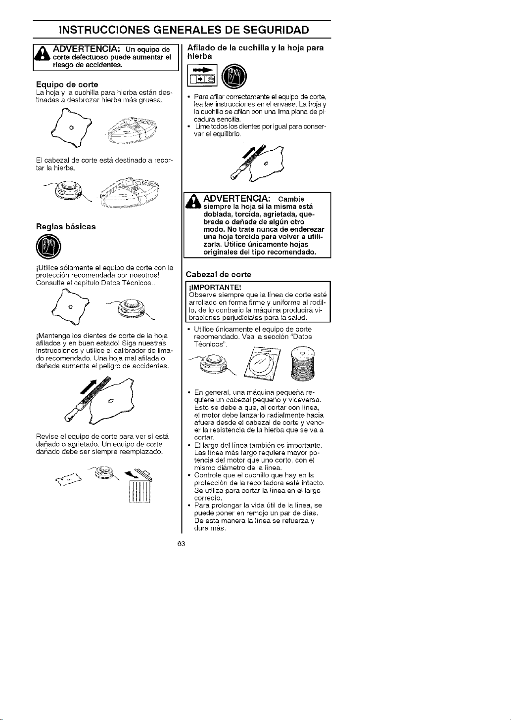
INSTRUCCIONES GENERALES DE SEGURIDAD
Afilado de la cuchilla y la hoja para
corte defectuoso puede aumentar el
1_ ADVERTENCIA: un equipo de
riesgo de accidentes.
Equipo de corte
La hoja y la cuchilla para hierba estAn des-
tinadas a desbrozar hierba mAs gruesa.
El cabezal de corte est&. destinado a recor-
tar la hierba.
Reglas basicas
iUtilice solamente el equipo de corte con la
protecci6n recomendada pot nosotros!
Oonsulte el capitulo Datos Tecnicos..
iMantenga los dientes de corte de la hoja
afilados yen buen estado! Siga nuestras
instrucciones y utilice el calibrador de lima-
do recomendado. Una hoja mal afilada o
daSada aumenta el peligro de accidentes.
hierba
• Para afilar correctamente el equipo de corte,
lea las instrucciones en el envase. La hoja y
la cuchilla se afilan con una lima plana de pi-
cadura sencilla.
• Ume todos los dientes por igual para conser-
vat el equilibrio.
_lb ADVERTENCIA: Carnbie
siempre la hoja si la rnisma esta
doblada, torcida, agrietada, que-
brada o dahada de alg_n otto
modo. No trate nunca de endetezar
una hoja torcida para volver a utili-
zarla. Utilice unicamente hojas
originales del tipo recornendado.
Cabezal de corte
ilMPORTANTE!
Observe siempre que la linea de corte este
arroliado en forma firme y uniforme al rodil-
Io. de Io contrario la m&.quina producira vi-
braciones perjudiciales para la salud.
• Utilice Onicamente el equipo de corte
recomendado. Vea la secci6n "Datos
Tecnicos".
Revise el equipo de corte para ver si est&.
daSado o agrietado. Un equipo de corte
daSado debe ser siempre reemplazado.
• En general, una m&.quina pequeSa re-
quiere un cabezal pequeSo y viceversa.
Esto se debe a que, al cortar con linea.
el motor debe lanzarlo radialmente hacia
afuera desde el cabezal de corte y venc-
er la resistencia de la hierba que se va a
cortar.
• El largo dei linea tambien es importante.
Las linea m&s largo requiere mayor po-
tencia dei motor que uno corto, con el
mismo di&.metro de la lieea.
• Oontrole que el cuchillo que hay en la
protecci6n de la recortadora este intacto.
Se utiliza para cortar la lieea en el largo
correcto.
• Para prolongar la vida 0til de la linea, se
puede porter en remojo un par de dias.
De esta manera la lieea se refuerza y
dura m&s.
63

MONTAJE
NOTA: AsegOrese de que el aparato este
montada correctamente segOn Io demos-
trado en este manual,
Montaje del manillar
• Afloje y quite el tornillo en la parte poste-
rior del acelerador,
• Deslice el acelerador en el lade derecho
del manillar (vea la ilustraci6n),
• Haga coincidir el orificio para el tornillo de
sujecion del acelerador con el officio del
manillar.
• Vuelva a colocar el tornillo en el orificio
en ta parte posterior det acelerador,
• Enrosque el toreillo a traves del acelera-
dot y el manillar. Apriete.
• Coloque las piezas de sujeci6n como
indica la ilustracion,
_,) //
• La sujeci6n del mange debe montarse
entre las marcas con fieehas en el tube,
• Apriete los tomiltos con la Ilave hexagonal.
Montaje del arnes
Montaje de la abrazadera del arnes
• Coloque la abrazadera superior del arnes
sobre el eje y coloque la abrazadera infe-
rior del arnes debajo del eje. Alinee los
huecos det tornillo de la abrazadera supe-
rior y la abrazadera inferior. La abrazad-
era debe montar sobre la marca con fie-
cha en el tubo.
NOTA: Coloque eI atambre del cable del
acelerador en et ranura de la abrazadera
inferior del ames antes de apretar los tor-
nillos,
• leserte dos tornillos en los hueeos para
tornillos.
• Apriete la abrazadera del arnes apretan-
do los tornillos con la llave hexagonal,
Ajuste del ames
• En la parte delaetera hay un desprendi-
miento de emergencia de facil acceso.
Use en cualquier situaci6n de emergencia
en que tenga que desprenderse rapida-
mente del ames y la maquina.
Distribucion pareja de la carga
sobre los hombros
• Un arnes y una maquina correctamente
ajustados facilitan considerablemente el
trabajo.
• Pongase el ames. Regule el arees para
obtener una postura de trabajo optima,
Regule las correas laterales para que el
peso se distribuya sobre los hombros de
forma pareja.
ADVERTENCIA: AI trabajar
con una desbrozadora, esta
siempre debe engancharse en el
arnes. De Io contrario, Ud. no
puede maniobrar la desbrozadora
de manera segura y esto puede
ocasionarle dal_os a Ud. o a tercer-
os. No utilice nunca un arnes con
el desprendimiento de emergencia
dafmdo.
Antes de hacer ajuste del arees o el mango.
es imprescindible que el motor este
comptetamente detenido.
NOTA: Puede ser necesado mover la
abrazadera del arnes en el eje para un
equilibrio apropiado det aparato.
64

MONTAJE
Altura correcta
Ajuste la correa de los hombros de manera
que el equipo de corte quede paralelo al
sue_o.
Equilibrio correcto
Deje que el equipo de corte descaese lig-
eramente en el suelo. Si se utiliza la hoja
de sierra, esta debe equilibrarse aproxima-
damente un dm por encima del suelo para
evitar eI contacto con piedras y objetos
similares. Mueva el abrazadera de1 arnes
para Iograr un buen equilibrio del aparato.
Montaje de la hoja y del cabezal
de corte
• AI moetar el equipo de corte es sumamente
importante que la guia de la pieza de ar-
rastre/brida de apoyo quede bien colocada
en el orificio central del equipo de corte. Un
equipo de corte mal montado puede causar
da[_os persona}es graves y/o mortates.
circunstancia se puede utilizar un
equipo de corte sin haber montado
antes la proteccion recomendada.
Yea la session " Datos tecnicos".
Si se monta una proteccion incor-
l& DVERTENCIA: Bajo ninguna
recta o defectuosa, esto puede
causar dal_os personales graves.
ilMPORTANTE!
Para poder utilizar la hoja de sierra o de
hierba, la maquh_a debe tener colocados el
maniliar, ia proteccion de hoja y el ames
oorreotos.
Montaje de la proteccibn de
hoja, hoja de hierba y cuchilla
de hierba
• La proteccion de la hoja/protecci6n combi-
nada (A) se engancha en ia sujeci6n del
tubo y se fija con un tomillo, iNOTA! Uti-
lice la proteccion de hoja recomendada.
Vea la secci6n "Datos tecnicos".
• Ooloque la pieza de arrastre (B) en el eje
de salida.
• Gire el eje de la hoja hasta que uno de los
orificios de la pieza de arrastre coincida
con un orificio de la caja de engranajes.
• Introduzca el pasador de seguridad (C)
en el orificio para bloquear el eje.
• Coloque la hoja (D). la cazoleta de apoyo
(E) y la brida de apoyo (F) en el eje de
salida.
• Monte la tuerca (G). La tuerca debe
apretarse con un par de 35-50 Nm
(3,5-5 kpm). Utilice la Ilave tubular del
juego de herramientas. Tome el mango
de ia Iiave Io mas cerca posible de la
proteccion de la hoja. La tuerca se aprie-
ta girando la Ilave en sentido contrario a
la rotaei6n (NOT,&: rosca izquierda).
65

MONTAJE
Montaje de la protector y la
cabezal de corte
• Montar la protector de la recortadora (A)
para trabajar con el cabezal de core.
La protecci6n de ta recortadora/protector
combinada se engancha en la sujeci6n
del eje y se fija con un tornillo (D).
; c
I
_D _/B
A
• Coloque la pieza de arrastre (B) en el eje
de salida.
• Gire el eje haste que uno de los orificies
de la pieza de arrastre coincida con un
orificio de la caja de engranajes=
• Introduzca et pasader de seguddad (C)
en el orificio para bloquear el eje.
• Enrosque el cabezal de corte (H) en el
sentido centrario al de rotaci6n.
I •
• El desmontaje se realiza en el orden in-
verso.
A
66

MANIPULACION DEL COMBUSTIBLE
Seguridad en el uso del com-
bustible
Nunca arranque la m&.quina:
1. Si detrain6 combustible sobre la maquina.
Seque cualquier residuo y espere a que
se evaporen los restos de combustible.
2. Si se salpico el cuerpo o las ropas, carn-
bie de ropas. Lave las pares del cuerpo
que han entrado en contacto con el
combustible. Use agua y jab6n.
3. Si hay fugas de combustible en la maqui-
na. Compruebe regularmente si hay fugas
en la tapa del dep6sito o en los conductos
de combustible.
Transporte y almacenamiento
• Almacene y transporte la maquina y el
combustible de manera que eventuales
fugas o vapores no puedan entrar en
contacto con chispas o llamas, por ejem-
pto. m#.quinas electricas, motores etectri-
cos. coetactos electricos/interruptores
de corriente o calderas.
• Para almacenar y transportar combus-
tible se deben utilizar recipientes disef_a-
dos y homologados para tal efecto.
• Si la maquina se va a almacenar por ue
periodo largo, se debe vaciar el dep6sito
de combustible. Pregunte en la estaci6n
de servicio mas cercana que hacer con
el combustible sobrante.
• Antes del almacenaje pro]ongado, limpie
bien la maquina y haga el servicio com-
pteto.
• La protecci6n para transportes del equi-
pc de corte siempre debe estar montada
durante el transporte o almacenamiento
de ta m&.quina.
• Para evitar el arranque imprevisto del mo-
tor, se debe quitar siempre el capuch6n de
encendido para el atmacenaje prolongado
de la maquina, si se va a dejar la m&.quina
sin vigitar y para efectuar todas las medi-
das de servicio previstas.
ADVERTENOIA: Para hacer Is
mezcla, compruebe que haya bue-
na ventilacion.
Carburante
iNOTA! El motor de la m&quina es de dos
tiempos y debe funcionar con una mezcla
de gasolina y aceite para motores de dos
tiempos. Para obtener una mezcla con las
proporciones correctas debe medirse con
precision la cantidad de aceite a mezclar.
En la mezcla de peque[_as cantidades de
combustible, los errores m#.s insignifi-
cantes en la medicion del aceite infiuyen
considerablemente en las proporciones de
la mezcla.
ADVERTENCIA: El combus- I
tible y los vapores de combustible I
son muy inflamables y pueden cau- I
sar daftos graves por inhalacion y
contacto con la piel. Pot consi-
guiente, al manipular combustible I
proceda con cuidado y procure que
haya buena venti aci6n.
Gasolina
NOTA! Use siempre gasolina sin plomo
de a}ta calidad.
• Este motor esta habilitado para fun-
cionar con gasolina sin plomo.
• El octanaje minimo recomendado es de 87
octaeos. Si usa gasoHna de menos de 87
octaeos, el motor puede pistonear. Esto
aumenta la temperatura del motor y puede
ocasionar averias graves del mismo.
• Para trabajar durante mucho tiempo en
altas revoluciones se recomienda el uso
de gasolina con mas octanos.
Aceite para motores de dos tiempos
• Para obtener el mejor resultado y funcio-
namiento, use el aceite JONSERED para
motores de dos tiempos, que ha sido ela-
borado especia]mente para nuestros mo-
tores de dos tiempos. Proporci6n de
mezcla 1:50 (2%).
• Para maximizar la vida de su recortadora,
usted puede elegir utilizar un aceite sinteti-
co de atta calidad, formulado y que ha sido
elaborado para motores de dos tiempos.
Proporci6n de mezcta 1:50 (2%).
• No utilice nunca aceite para motores de
dos tiempos fuera borda refrigerados por
agua (outboard oil).
• No utilice nunca aceite para motores de
cuatro tiempos.
Aceite para
Gasolina
motores de dos
tiempos
2%(1:50)
Litros
5
10
15
67
Litros
0,10
0,20
0,30

MANIPULACION DEL COMBUSTIBLE
Mezcla
• Siempre haga la mezcla de gasolina y
aceite en un recipiente limpio, homologa-
do para gasolina.
• Primero, ponga la mitad de la gasofina
que se va a mezclar. Luego, a_ada todo
e] aceite y agite ]a mezc]a. A continua-
ci6n, a_ada el resto de la gasolina.
• Agite bien la mezcla de combustible
antes de ponerla en el dep6sito de com-
bustible de la maquina.
• No mezc]e m#.s combustible que e] ne-
cesafio para utifizar un mes como m#.xi-
mo.
• $i no se ha uti]izado la maquh_a por un
tiempo prolongado, vacie el dep6sito de
combustible y limpielo.
,_ ADVERTENCIA: El silenciador
se calienta mucho, tanto durante el
funcionamiento como despues de
la parada. Incluso funcionando
este en ralenti. Tenga presente el
peligro de incendio, especialmente
al manejar sustancias y/o gases in-
f amab es.
Repostaje
ADVERTENCIA: Las siguientes
medidas preventivas reducen el ties-
go de incendio:
No fume ni ponga objetos calientes
cerca del combustible.
No haga nunca el repostaje con el
motor en marcha. Apague el motor
y deje que se enfrie unos minutos
antes de repostar.
Para repostar, abra despacio la
tapa del deposito de combustible
para evacuar lentamente la eventu-
al sobrepresion.
Despues de repostar, apriete bien
la tapa del deposito de combus-
tible. Antes de arrancar, aparte
siempre la maquina del lugar de
repostaje.
• Umpie alrededor de la tapa del dep6sito.
Los residuos en el dep6sito ocasionan
problemas de funcionamiento.
• AsegQrese de que el combustible este
bien mezclado sacudieedo el recipiente
antes de Ilenar e] dep6sito.
68

ARRANQUEYPARADA
Control antes de arrancar
• Controle que la hoja no tenga grietas en
la base de los dientes ni en el orificio
central El motivo mas comtJn de la
aparicion de grietas es que duraete el
limado se han formado esquinas agudas
en la base de los dientes, o la hoja se
utilizo con dientes desafilados. Cambie
la hoja si descubre grietas.
\
S
• Controle que la brida de apoyo no tenga
grietas debido a fatiga de1material o por
estar demasiado apretada. Cambie la
brida de apoyo si encuentra grietas.
• Controle que la contratuerca no haya
perdido la fuerza de bloqueo. El bloqueo
de la tuerca debe tener un par de por
lo menos 1,5 Nm. El par de apriete de la
contratuerca debe set de 35-50 Nm.
Arranque y parada
Q@@
ADVERTENCIA: Antes de ar-
rancar la maquina debe montarse
la cubierta del embrague completa
con el tubo, de Io contrario el em-
brague puede zafar y provocar
dal_os personales. Antes de arran-
car, aparte siempre la maquina del
lugar de repostaje. Coloque la
maquina sobre una base firme.
Controle que el equipo de corte no
pueda atascarse en algL_n objeto.
AsegL_rese de que no haya perso-
nas desautorizadas en la zona de
trabajo, de Io contrario se corre el
riesgo de ocasionar graves dahos
personales. La distancia de seguri-
dad es de 15 metros (50 pies).
Motor frio
Bomba de combustible: Presione 10
veces la burbuja de goma de la bornba de
combustible hasta que comience a Ile-
narse de combustible. No es necesario
Ilenarla totaimente.
• Coetrole que el cabezal de corte y la pro-
tector de la recortadora no esten da{_ados
ni presenten grietas. Cambie el cabezal o
la protector de la recortadora si han recibi-
do golpes o es_n agrietados.
• Nunca utilice ia m_tquina sin la protec-
ci6n o con uea proteccion defectuosa.
• Todas las cubiertas deben estar correc-
tamente montadas yen buenas condi-
ciones antes de arrancar la m_tquina.
Estrangulador: Coloque la palanca azul
del estrangulador de la motor a la posicion
estrangulamiento.
,"¢ / -_- .... _11
Arranque
Presione el cuerpo de la mb.quina contra el
suelo con la mano izquierda (ATENOION:
iNo con el pie!). Agarre la empui_adura de
arranque con la mano derecha. NO
apriete el gatillo aeelerador. Tire despa-
cio de la cuerda con la mano derecha,
hasta sentir una resistencia (los dientes de
arranque engranan), y despues tire rapido
, con fuerza.
Nunca enrosque el cuerda de
arranque alrededor de la mano.
69

ARRANQUEYPARADA
Repita tirar de la cuerda hasta que el mo-
tor suene como si este intentando arran-
car. Apriete eI gatillo acelerador para de-
sactivar el estrangulador. Sujete el gatillo
aeeleradot y tire del cuerda hasta que el
motor arranca.
NOT.&: Si el motor se apaga, coloque la
patanca azul de1 estrangulador de la motor a
la posicion estrangulamiento y repita los
instrucciones de arranque.
iPRECAUCION! No extraiga el cuerda de
arranque al maximo, y no suelte la em-
puSadura de arranque si ha extraido todo
el cuerda. Etlo puede ocasionar averias en
la mS.quina.
Motor caliente
Con un motor caliente, apriete y sujete el
gatillo acelerador. Tire de la cuerda del ar-
rancador hasta que el motor funcione.
iNOTA!
No poner ninguna parte del cuerpo en la
superficie marcada. El contacto puede
causar quemaduras en la piel o sacudidas
electdcas si el excitador de ignici6n es de-
fectuoso. Utilice siempre guantes protec-
tores. No emplee nunca una maquina
con un excitador de ignici6n defectuoso.
Acelerador con fiador de acelera-
cion de arranque:
Para obtener la posici6n de aceleraci6n de
arranque, presionar primero el fiador del
acelerador y el acelerador, y despues
3resionar el boton de aceleraci6n de arran-
que (A). A continuaci6n, soltar el fiador del
acelerador y el acelerador, y despues el
bot6n de aceleraci6n de arranque. Ahora,
esta activada la funci6n de aceleraci6n de
arranque. Para reponer el motor en ralenti,
3resionar el fiador dei acelerador y el
aceterador.
Parada
Para detener el motor, empuje y sostenga el
interruptor stop en la posici6n STOP hasta
que el motor se haya detenido por completo.
iNOTA! El interruptor retorna automatica-
mente a la posici6n de arranque. Por con-
siguiente, antes de realizar trabajos de
montaje, control y/o mantenimiento se
debe quitar el capuch6n de encendido de
la bujia para evitar el arranque imprevisto.
ADVERTENClA: Cuando el
motor es arraneado con el estran-
gulador en la posicion activada o
de aceleracion de arranque, el
equipo de corte comienza a girar
inmediatamente,
7O

TI_CNICA DE
Instrucciones generales de
trabajo
ilMPORTANTE!
Esta secci6n trata reglas de seguddad
fundamentales para el trabajo con la
recortadora. Ouando se vea en una situa-
ci6n insegura para contieuar el trabajo,
debe consultar a un experto. Pongase en
contacto con su distribuidor autorizado del
servicio. Evite todo uso para el cual no se
sienta suficientemente calificado.
Antes del uso, Ud. debe haber entendido
la diferencia entre desbroce forestat, des-
broce de hierba y recorte de hierba.
Reglas basicas de seguridad
/hQOO
1. Observe el entorno para:
• Comprobar que no hayan personas,
animales, etc., que puedan influir en su
control de la m_tquina.
• Para evitar que personas, animales,
etc. entren en contacto con el equipo
de corte u objetos lanzados por el
equipo de corte.
• iNOTA! No use nueca una maquina si
no tiene posibilidad de pedir auxilio si
se produce un accidente.
2. No trabaje en condiciones atmosfericas
desfavorables como niebla, Ituvia intensa,
tempestad, frio ietenso, etc. EI trabajo con
mal tiempo es fatigoso y puede crear
circunstancias peligrosas, como terreno
resbaladizo, cambio imprevisto de la direc-
ci6n de derribo de los arboles, etc.
3. Compruebe que pueda caminar y manten-
erse de pie con seguridad. Vea si hay
eventuales impedimentos para desplaza-
mientos imprevistos (raices, piedras, ramas
fosos, zanjas, etc.). Proceda con sumo cui-
dado al trab_ _r en terreno inciinado.
4. Siva a trasladarse de un lugar a otto, apa-
gue primero el motor. Para desplazamientos
largos y al transportar el equipo, se debe
utitizar la protecciSn para transportes.
5. No apoye nunca la m&quina con el motor
en marcha o mientras que el equipo de
certe est& rotando.
TRABAJO
Principios basicos del desbroce
• Utilice siempre el equipo correcto.
• Utilice siempre un equipo bien adaptado.
• Siga las instrucciones de seguridad.
• Organice bien el trabajo.
• Siempre haga girar ia hoja a m#txima ve-
iocidad al iniciar el corte.
• Utilice siempre hojas bien affladas.
• Evite el impacto con las piedras.
ADVERTENCIA: Ni el usuario d_
la maquina ni ninguna otra persona
debe intentar quitar la vegetacion
cortada cuando el motor o el equi-
po de corte ann est&n girando,
dado que esto comporta riesgo de
dahos graves. Pare el motor y el
equipo de corte antes de quitar la
vegetacion que se ha enrollado en
el eje de la hoja, porque de Io con-
trario pueden producirse daflos.
Durante el uso y poco despues, el
engranaje angulado puede estar
caliente. El contacto con el mismo
puede ocasionar quemaduras.
ADVERTENCIA: Advertencia de
objetos lanzados. Utilice siempre ga-
las protectoras homologadas. No se
incline nunca sobre la proteccion del
equipo de corte. Hay riesgo de lanza-
miento de piedras, suciedad, etcet-
era, contra los ojos; causando ce=
guera o daflos graves. Mantenga ale-
jados a los terceros. Los nihos,
animales, curiosos y ayudantes de-
ben mantenerse fuera de la zona de
seguridad de 15 metros (50 pies).
Pare la maquina inmediatamente si
alguien se acerca. Nunca gire con la
maquina si no ha verificado antes
que la zona de seguridad atr_s de
Ud. esta vacia.
ADVERTENCIA: A veces,se
atascan ramas o hierba entre la pro-
teccion y el equipo de corte. Antes
de retirarlos, pare siempre el motor.
Tecnica basicas de trabajo
Despues de cada memento de trabajo re-
duzca siempre la velocidad del motor a ra-
lenti. Un tiempo demasiado largo a maxima
velocidad sin que el motor este cargado
puede averiar seriamente el motor.
Metodos de trabajo
ADVERTENCIA: Evite cortar con
la zona de corte de la hoja entre las
12 y 3 horas. Por la velocidad de ro-
tacion de la hoja pueden producirse
reculadas justo en esta zona de
corte de la hoja, cuando se intenta
cortar troncos mas gruesos.
71

TECNICA DE TRABAJO
• Antes de comenzar a desbrozar, controie
la zona de desbroce, las caracteristicas
del terreno, la pendiente, si hay piedras,
pozos, etc.
• Comience iuego en el extremo mas faeil
del sector, para obtener una buena abertu-
ra de1desbroce.
• Trabaje sistematicamente de adeiante ha-
cia atr#ts, a traves del sector, y cubriendo
en cada barrido unos 4-5 metros (12-15
pies). De esta manera, se aprovecha todo
el alcance de ia m_tquina hacia Ios dos la-
dos y el operario trabaja m#ts facilmente y
con mas variaci6
• El trayecto de avance debe ser de aproxi-
madamente 75 metros (250 pies) de largo.
Vaya moviendo el dep6sito de combustible
a medida que avanza.
• En terrenos escarpados, el trayecto de
avarice debe ser perpendicular a la pen-
diente. Es mucho m_ts facil deplazarse
por una pendiente de lado que subirla y
bajarla.
• El trayecto de avance debe planificarse
para no tener que cruzar zanjas u otros
obstaculos del terreno. Adapte tambien el
trayecto de avarice alas condiciones actu-
ales del viento, de manera que los troncos
desbrozados caigae en la zona ya desbro-
zada del terreno.
F'!la" --. _.
• Corte la hierba con un movimiento de
bartido pendular, donde el movimiento
de derecha a izquierda es el de des-
broce y el de izquierda a derecha, el de
retorno. Haga trabajar a la parte izquier-
da de la hoja (entre las 8 y las 12).
• Sial desbrozar la hierba la hoja es inclina-
da un poco hacia la izquierda, ia hierba se
acumula en una hiiera que es mas facil de
juntar posteriormente, por ejemplo al
rastriilar.
• Trate de trabajar siguiendo un ritmo.
P#trese firmemente con ias piemas abier-
tas. Avance despues dei movimiento
de retomo y p#trese nuevamente con fir-
meza.
• Deje que ia cazoleta de apoyo toque Iiger-
amente el suelo. Su funci6n es evitar que
ia hoja corte en el suelo.
• Para evitar que la vegetacion cortada se
enrolle en la hoja, haga Io siguiente:
• Trabaje siempre a maxima velocidad.
• Durante el movimiento de retomo, evite
barrer sobre Io que acaba de cortar.
• Pare el motor, afloje el arnes y apoye la
m&.quina en el suelo antes de recoger la
vegetacion cortada.
Recorte de hierba con el cabezal de
corte
Recorte
Desbroce de hierba con hoja para
hierba
QOO
• Las hojas y cuchillas para hierba no deben
utilizarse para tallos leSosos.
• Para todo tipo de hierba alta o gruesa se
utiliza la hoja para hierba.
• Mantenga el cabezal de corte justo por enci-
ma del suelo, en posici6n inclinada. Es ia
punta del hi]o la que reaIiza et trabajo. Deje
que el hilo trabaje con su propio ritmo.
Nunca Io presione contra la vegetacion que
quiere segar.
• El hilo corta con facilidad ia hierba y las
malas hierbas que hay contra paredes,
cercas, arboles y arriates, pero tambien
puede daSar Ia corteza delicada de
arboles y arbustos, y postes de cercas.
72

TECNICA DE TRABAJO
• Disminuya el peligro de daSos en las
piantas acortando el hilo a 10-t2 cm
(4-5 pulgadas) y disminuyendo las revo-
luciones del motor.
• AI recortar y raspar debe utilizar una ve-
Iocidad un poco menor que la acelera-
ci6n maxima para que el hilo dure m#ts y
el cabezal de corte se desgaste menos.
Raspado
QOO
• La tecnica de raspado corta toda la vege-
taci6n no deseada. Mantenga el cabezal
de corte justo por encima del suelo, en
posicion inclinada. Deje que la punta de1
hilo golpee el suelo alrededor de arboles,
columnas, estatuas, etc. ATENOION:
Esta teceica aumenta el desgaste de la
linea.
• El hilo se desgasta mils rfipido y se debe
alimentar m_ts seguido al trabajar contra
piedras, ladrillos, hormig6n, cercas de
metal, etc. que al estar en contacto con
#trboles y cercas de madera.
Corte
QOO
• La recortadora es ideal para cortar en lu-
gares que son dificitmente accesibles para
un cortacesped comOn. AI cortar, manten-
ga el hilo paralelo al suelo. Evite presionar
el cabezal de corte contra el suelo para no
da[_ar el cesped ni el equipo.
• Durante el corte normal evite que el ca-
bezal de corte este en contacto continuo
con el suelo. Un contacto continuo de
este tipo puede causar da[_os y des-
gaste en el cabezal de corte.
Barrido
QOO
• El efecto ventilador det hilo giratorio
puede utilizarse para una limpieza rapida
y senciHa. Mantenga el hilo paralelo y
por encima de la superficie a barrer y
mueva la m_tquina de un lado a otro.
/
\
• AI cortar y barrer debe utilizar la acelera-
ci6n m_txima para obtener un buen resul-
tado.
ADVERTENCIA: Ni el usuario de
A
la maquina ni ninguna otra persona
debe intentar quitar la vegetacion
cortada cuando el motor o la hoja
ann estan girando porque esto
puede provocar dahos graves. Pare
el motor y la hoja antes de quitar la
vegetacion que se ha enroscado en
el eje de la hoja, porque de Io contra-
rio pueden producirae dafms. Du-
rante el uso y poco despues, el en-
granaje angulado puede estar cal-
iente. El contacto con el mismo
puede ocasionar quemaduras.
i_ ADVERTENCIA: Cuidado con
los objetos lanzados. Utilice aiempre
proteccion ocular. No se incline nun-
ca sobre la proteccion del equipo de
corte. Pueden salir lanzadas piedraa,
basura, etc. hacia los ojos y causar
ceguera o heridas graves. Mantenga
alejados a los terceros. Los nihos,
animales, curioaoa y ayudantes de-
ben mantenerae fuera de la zona de
seguridad de 15 metros (50 pies).
Pare Is maquina inmediatamente si
alguien se acerea,
73

MANTENIMIENTO
El due[_o es responsable de adquirir todo el
mantenimiento requerido como Io define en
el manual de instrucciones.
_IbADVERTENCIA: El mantenimien-
to incorrecto podria provocar dafms
serios al motor o personales.
Carburador
Su producto Jonsered ha sido construido y
fabricado conforme a especificaciones que
reducen los gases de escape t6xicos.
Cuando el motor ha consumido 8-10
dep6sitos de combustible, se dice que el
motor ha sido rodado. Para asegurarse de
que funcione de la mejor manera y despida
la menor cantidad posible de gases toxicos
despues del periodo de rodaje, contacte a
su distribuidor autorizado det servicio para
que ajuste su carburador.
ADVERTENCIA: Antes de ar-
rancar la maquina debe montarse la
cubierta del embrague completa con
el tubo, de Io contrario el embrague
puede zafar y provocar dahos per-
sona es.
Functionamiento
• El regimen del motor se controla me-
diante el aceterador y el carburador. En el
carburador se efectLia la dosificaci6n de
la mezcla de aire y combustible.
• Con el tornillo T se regula la posici6n del
acelerador en ralenti. El ratenti se au-
menta girando el toreillo Ten el sentido
de las agujas del reloj y se reduce
girandolo en sentido contrario alas agu-
jas del reloj.
Reglaje basico
• El reglaje b#tsico del carburador se Ileva a
cabo en las pruebas que se hacen en f#tbri-
ca. El reglaje final debe ser reaIizado por un
tecnico especializado.
,_ ADVERTENCIA: El de
corte tal vez pueda girar al hacer
ajustes al carburador. Use su equipo
de proteccion y observe todas las
instrucciones de seguridad. Este se-
guro que el equipo de corte pare de
dar vueltas euando el motor este in-
activo. Cuando el aparato este apa-
gado, cercibrese de que los equipo
de corte hayan parado completa-
mente antes de sentarlo en algae
lado.
iNOTA! Si el equipo de corte gira en ralenti,
debe girarse el tornillo de ralenti- Ten senti-
do contrario alas agujas del reloj hasta que el
equipo de corte quede inm6viL
equipo
Regimen recomendado en ralenti:
Yea ta secci6n "Datos Tecnicos".
Aceleracibn maxima recomendada:
Vea la seccion "Datos Tecnicos".
Reglaje definitivo del regimen de
ralenti-T
Regule el regimen de ralenti con el tornillo T,
si es necesario un reajuste. Gire primero el
tornillo de ratenti Ten el sentido de las agu-
jas del reloj, hasta que comience a girar el
equipo de corte. Despues gire el tornillo en el
sentido contrario, hasta que el equipo de
corte se detenga. Et regimen de ralenti es
correcto cuando el motor funciona en forma
uniforme en cada posicion. Tambien debe
existir un buen margen hasta el regimen en
que empieza a girar el equipo de corte.
'_ Toreillo de
'_" _ aJ_eStre de
,_ADVERTENCIA: Si no puede
regular el regimen en ralenti para
que el equipo de corte deje de girar,
consulte a su distribuidor autorizado
del servicio. No utilice la maquina
hasta que no este eorrectamente
regulada o reparada.
Seguridad del aparato y su
mantenimiento
Antes de realizar cuatquier tarea de man-
tenimiento, salvo reglajes en el carburador,
desconecte la bujia.
Silenciador
iNOTA! El silenciador tiene un catalizador
diseSado para reducir los gas de escape
daSosos.
74

MANTENIMIENTO
El silenciador est'. diseSado para amortiguar
el ruido y para apartar del usuario los gases
de escape. Los gases de escape est#tn cal-
ientes y pueden contener chispas que pue-
den ocasionar incendios si se dirigen los
gases a materiales secos e inflamabies.
El si_enciador incorporan uea rejilla apaga-
chispas. El rejilla debe ser comprobado y
en caso de necesidad, limpiar por una dis-
tribuidor autorizado del servicio. Si el rejil-
la presenta dahos, se debe cambiar el
rejilla.
Si el rejiHa se obstruye con frecuencia,
esto puede ser se[_al de que el catalizador
no funoiona correctamente. Consulte a su
distribuidor para un inspeccion. Si el rejilla
se obstruye, la maquina se recatienta y se
da_an el cilindro y el pist6n.
iPRECAUCION! No utilice nunca la
maquina con un silenciador en mal estado.
con catalizador se calienta mucho
durante el uso y permanece caliente
aOn luego de apagado el motor. Lo
mismo rige para la marcha en ra-
ienti. Su contacto puede quemar la
I,_ DVERTENCIA: El silenciador
piel. iTenga en cuenta el peligro de
incendio!
del silenciador hay sustancias
quimicas que pueden ser cancerige-
nas. Evitar el contacto con estas
& ADVERTENCIA: En el interior
sustancias si se dafm el silenciador.
ADVERTENCIA: Recuerde que:
Los gases del motor contienen
monoxido de carbono que puede
provocar intoxicacion. Por eso, nun-
ca arranque ni haga funcionar la
maquina en ambientes cerrados, o
cuando no exista una buena circula-
cion de mire. Los gases de escape
del motor estan calientes y pueden
contener chispas que pueden provo-
car incendio. Por esa razon, inunca
arranque la maquina en interiores o
cerca de material inflamable!
Tornillos del
silenciador
Rejilla
Bujia
Los factores siguientes afectan al estado
de la bujia:
• Carburador mal regulado.
• Mezcta de aceite inadecuada en el com-
bustible (demasiado aceite o aceite in-
adecuado).
• Filtro de mire sucio.
Estos factores producen revestimientos en
los electrodos de la bujia que pueden oca-
sionar perturbaciones del funcionamiento y
dificultades de arranque. Si la potencia de
la m_tquina es demasiado baja, si es dificil
arrancar la maquina o si el ralenti es irregu-
lar: revise primero la bujia antes de tomar
otras medidas. Si la bujia esta muy sucia,
limpiela y compruebe que la separacion de
los electrodos sea de 0,6 mm (0,024 de pul-
gada). La bujia debe cambiarse aproxima-
damente despues de un mes de funciona-
miento o mas a menudo si es necesario.
0,6 mm (0,024 de pulgada)
iPRECAUCION! iUtilice siempre et tipo de
bujia recomendado! Una bujia incorrecta
puede arruinar el pist6n y el cilindro.
Filtro de mire
El filtro de mire debe limpiarse regular-
mente de polvo y suciedad para evitar:
• Fallos del carburador
• Problemas de arranque
• Reducci6n de la potencia
• Desgaste innecesario de ias piezas del
motor.
• Un consumo de combustible excesivo.
jj_
Limpie el filtro cada 25 horas de funciona-
miento o mas seguido si trabaja en un en-
torno muy polvoriento.
75

MANTENIMIENTO
Limpieza del filtro de aire
Desmonte _acubierta del fiitro de aire y re-
tire el filtro. Lavelo en agua jabonosa cal-
iente. Aclare el filtro totalmente. Controle
que el filtro este seco antes de volver a
montarlo. Un filtro utilizado duraete mucho
tiempo no puede limpiarse de1 todo. Por
tanto, hay que cambiarlo a intervalos regu-
lares. Un filtro de aire averiado debe
cambiarse.
Engranaje angulado
El engranaje angulado se entrega de fabri-
ca con la cantidad adecuada de grasa. No
obstante, antes de empezar a utilizar ia
maquina, verifique que el engranaje este
Ileno con grasa hasta 1as 3/4 partes. Use
grasa especial de JONSERED.
Generalmente, el lubricante en el cuerpo
de1 engraeaje no requiere cambiarse ex-
cepto cuando se realizan reparaciones.
Afilado de la cuchilla y la hoja
para hierba
ADVERTENCIA: Pare siempre
el motor antes de trabajar con algu-
na parte del equipo de corte. Este
continua girando incluso despues
de haber soltado el acelerador. Con-
trole que el equipo de corte se haya
detenido completamente y desco-
necte el cable de la bujia antes de
comenzar a trabajar.
• Para afilar correctamente el equipo de
corte, lea ias instrucciones en el envase.
• La hoja y la cuchilla se afilan con una
lima plana de picadura sencilla.
• Lime todos los dientes pot igual para con-
servar el equflibfio.
ADVERTENCIA: Cambie
siempre la hoja si la misma esta do-
blada, torcida, agrietada, quebrada o
dahada de algOn otto modo. No trate
nunca de enderezar una hoja torcida
para volver a utilizarla. Utilice _nica-
mente hojas originales del tipo re-
comendado.
76
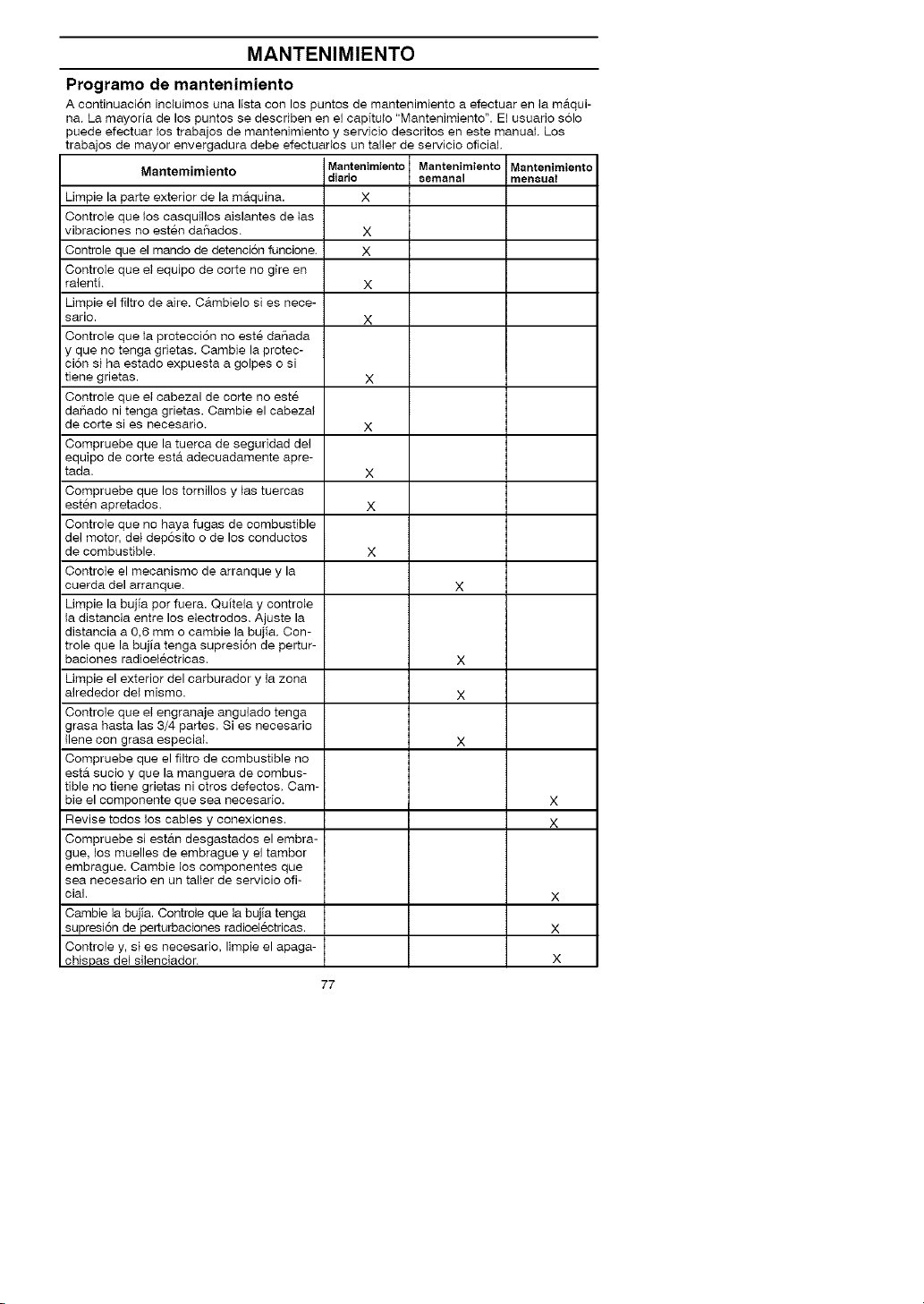
MANTENIMIENTO
Programo de mantenimiento
A continuaci6n incluimos una lista con los puntos de mantenimiento a efectuar en la m_.qui-
na. La mayoria de los puntos se describen en el capitulo "Mantenimiento". El usuario solo
puede efectuar los trabajos de mantenimiento y servicio descritos en este manual. Los
trabajos de mayor envergadura debe efectuarlos un taller de servicio oficial.
Mantemimiento Mantenimiento Mantenimiento Mantenimiento
Umpie la parte exterior de la mAquina. X
Controle que los casquillos aislantes de las
vibraciones no estee da_ados. X
Controle que el mando de detenci6n funcione. X
Controle que el equipo de carte no gire en
ralenti. X
Limpie el filtro de aire. Cgtmbielo si es nece-
sario. X
Controle que la proteccion no este daSada
y que no tenga grietas. Cambie la protec-
cion si ha estado expuesta a golpes o si
tiene grietas. X
Controle que el cabezal de corte no este
daSado ni tenga grietas. Cambie el cabezat
de conte si es necesario. X
Compruebe que la tuerca de seguridad del
equipo de corte estgt adecuadamente apre-
tada. X
Compruebe que los tornillos y las tuercas
esten apretados. X
Controle que no haya fugas de combustible
del motor, det dep6sito o de los conductos
de combustible. X
Controle el mecanismo de arranque y la
cuerda del arranque. X
Umpie la bujia por fuera. Quitela y controle
la distancia entre los electrodes. Ajuste la
distancia a 0,6 mm o cambie la bujia. Con-
trole que la bujia tenga supresi6n de pertur-
baciones radioelectricas. X
Umpie el exterior del carburador y la zona
alrededor del mismo. X
Controle que el engranaje angulado tenga
grasa hasta las 3/4 partes. Si es necesario
Ilene con grasa especial. X
Compruebe que el filtro de combustible no
esta sucio y que la manguera de combus-
tible no tiene grietas ni otros defectos. Cam-
bie el componente que sea necesario. X
Revise todos los cables y conexiones. X
Compruebe si est#tn desgastados el embra-
gue, los muelles de embrague y el tambor
embrague. Cambie los componentes que
sea necesario en un taller de servicio off-
cial. X
Cambie la bujia. Controie que la bujia tenga
supresi6n de perturbaciones radioelectricas. X
Controle y, si es necesario, Iimpie el apaga-
chispas del silenciador. X
diario 8emanal mensual
77
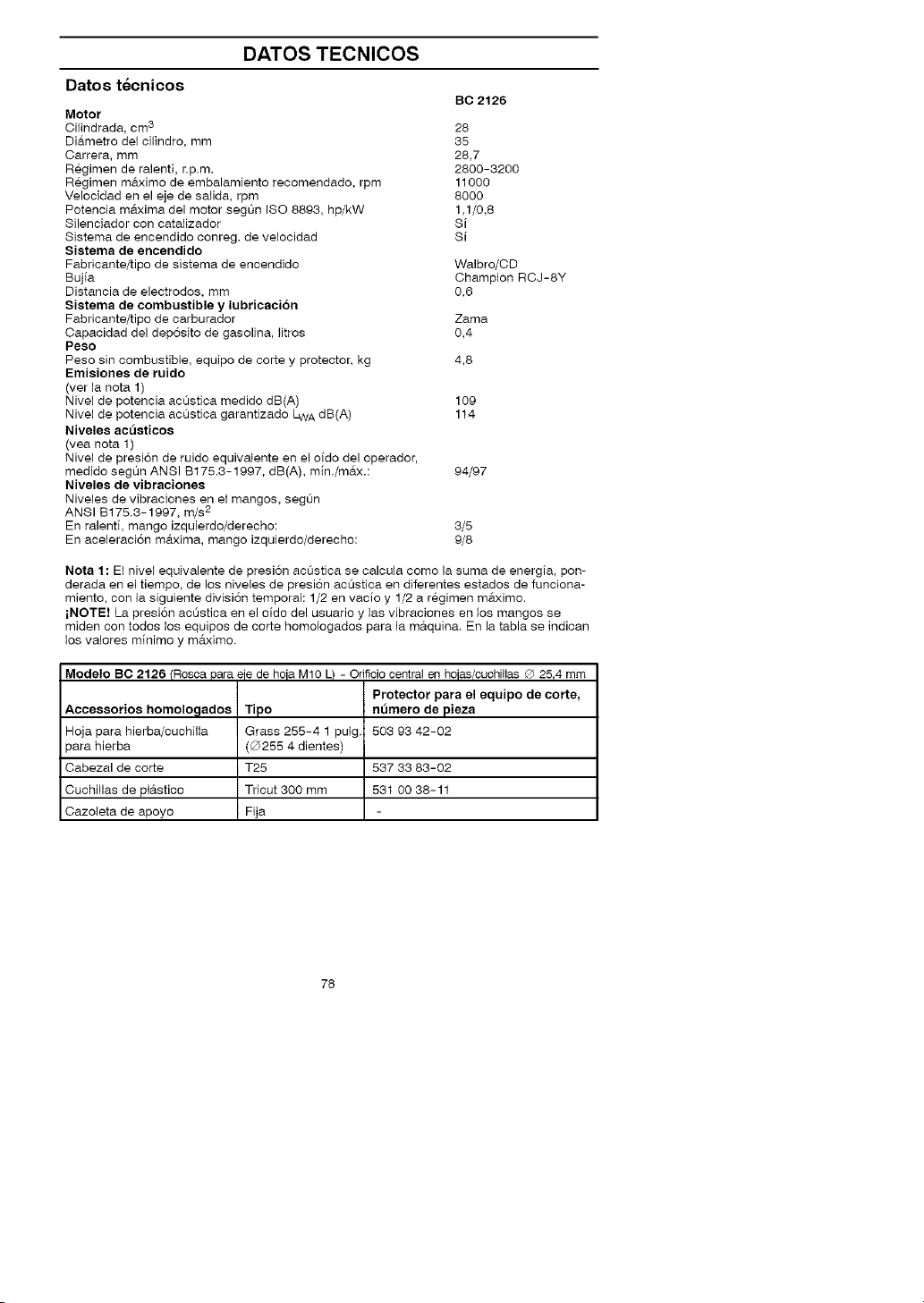
DATOS TECNICOS
Datos tecnicos
Motor
Cilindrada, cm 3 28
DiAmetro de1 cilindro, mm 35
Carrera, mm 28,7
Regimen de raleeti, r.p.m. 2800-3200
Regimen maximo de embalamieeto recomendado, rpm 11000
Velocidad ee el eje de salida, rpm 8000
Potencia maxima del motor segL_e ISO 8893, hp/kW 1,1/0,8
Silenciador con catalizador Si
Sistema de enceedido conreg, de velocidad Si
Sistema de encendido
Fabficante/tipo de sistema de encendido
Bujia
Distancia de electrodos, mm
Sistema de combustible y lubricacion
Fabficante/tipo de carburador Zama
Capacidad del dep6sito de gasolh_a, }itros 0,4
Peso
Peso sin combustible, equipo de corte y protector, kg 4,8
Emisiones de ruido
(ver la nora 1)
Nivel de potencia acQstica medido dB(A) 109
Nivel de potencia acQstica garantizado LWA dB(A) 114
Niveles ac_sticos
(vea nota 1)
Nivel de presi6n de ruido equivatente en el oido del operador,
medido segL_n ANSI B175.3-1997, dB(A), min./mAx.: 94/97
Niveles de vibraciones
Niveles de vibraciones en el mangos, segL_n
ANSI B175.3-1997, m/s2
En ralenti, mango izquierdo/derecho: 3/5
En aceleraci6n maxima, mango izquierdo/derecho: 9/8
Nota 1: El nivel equivalente de presi6n acListica se calcula como la suma de eeergia, pon-
derada ee el tiempo, de los niveles de presi6n acQstica ee diferentes estados de funciona-
mieeto, con la siguieete divisi6n temporal: 1/2 en vacio y 1/2 a regimen maximo.
iNOTE! La presi6e acQstica en el oido del usuario y las vibraciones ee los mangos se
midee con todos los equipos de corte homologados para la mAquiea. En la tabla se indican
los valores mieimo y mAximo.
BC 2126
Walbro/CD
Champion RCJ-8Y
0,6
Modelo BC 2126 (Rosca para eje de hoje M10 L) - Otificio central en hojes/cuchiHas ® 25,4 mm
Accessorios homolo£1ados
Hoja para hierba/cuchilla
para hierba
Cabezal de corte
Cuchillas de plAstico
Cazoleta de apoyo
Tipo
Grass 255-4 1 pulg.
(0255 4 dientes)
T25
Tricut 300 mm
Fija
Protector para el equipo de corte,
nt_mero de pieza
503 93 42-02
537 33 83-02
531 00 38-11
78
DECLARACION DE GARANTIA DE CONTROL
DE EMISION DE U.S. EPA / CALIFORNIA /
AGENCIA AMBIENTAL CANADIENSE
SUS DERECHOS Y OBLIGACIONES
DE GARANTIA:
La Agencia de Protecci6n Ambiental de los
Estados Unidos, la Junta de Recursos Ambi-
entales de California, la Agencia Ambiental
Canadiense y Jonsered se complacen en ex-
plicar la garantia con la que cuenta el sistema
de control de emisi6n en su motor pequeSo,
modelo 2005 y mrs adelante, para uso fuera
de carretera. En California, todos los motores
pequeSos para uso fuera de carretera deben
ser dise[_ados, construidos y equipados para
satisfacer tas rigurosas normas antihumo que
posee el estado.
Jonsered deber_t garantizar el sistema de
control de emision en su maquina de motor
pequeSo para uso fuera de carretera bor los
periodos de tiempo que explicamos a conti-
nuacion y con la condicion de que su m&.qui-
na de motor peque[fo para uso fuera de car-
retera no haya sufrido ningt3n tipo de abuso,
negligencia o mantenimiento inapropiado. Su
sistema de control de emision incluye piezas
tales como el carburador y el sistema de igni-
ci6n. Donde exista una condici6n que re-
quiera reparaci6n bajo garantia, Jonsered re-
parara gratis su motor peque[fo para uso
fuera de carretera. Los gatos cubiertos bajo
la garantia incluyen el diagn6stico, las piezas
y labor,
CUBIERTA DE GARANTIA DEL FAB-
RICANTE:
Si cualquier pieza relacionada con el sistema
de emisi6n de su motor (como hemos enum-
erado en la lista de piezas de control de emi-
si6n bajo garantia) se encontrara defectuosa
o defectos en el material o en la labor del mo-
tor causaran que tal pieza comenzara a fallar,
la pieza sera reparada o reemplazada por
Jonsered.
GARANTIA DE RESPONSABILIDAD
DE DEL DUENO:
Como duello de una maquina de motor pe-
queSo para uso fuera de carretera, usted
ser#t responsabie por eI mantenimiento ade-
cuado en los periodos previamente progra-
mados y enumerados en su manual de
iestrucciones. Jonsered recomienda que
guarde todos los recibos que indiquen que
se ha desempeSado mantenimiento en su
maquina de motor pequeSo para uso fuera
de carretera, pero Jonsered no podr#t negar
el servicio bajo garantia 0nicamente a cau-
sa de la falta de recibos o por el incumpli-
miento de su parte en asegurarse que el
mantenimiento programado haya sido de-
sempeSado. Como dueSo de una m#tquina
de motor pequeSo para uso fuera de carret-
era, usted deber#t contar con el conocimien-
to de que Jonsered puede negar la cubierta
bajo garantia si su m&.quina de motor pe-
queSo para uso fuera de carretera o aiguna
pieza de la misma ha dejado de funcionar
debido al abuso, negligencia, mantenimien-
to inapropiado, modificaciones no aproba-
das o el uso de piezas que no hayan sido
fabricadas o aprobadas por el fabricante
original del equipo. Es resbonsabilidad suya
et Ilevar su maquina de motor pequeSo para
uso fuera de carretera a un oentro de repara-
ci6n autorizado Jonsered tan pronto como se
presente el problema. Las reparaciones bajo
garantia deber_tn ser completadas en un per-
iodo de tiembo razonable, que no exceda los
30 dias. Si cuenta usted con alguna pregunta
en relaci6n a sus derechos y responsabili-
dades de garantia, usted deber#t comunicarse
con su centro de servicio autorizado mrs cer-
cano o Ilamar a Jonsered al
1-916-383-3511.
FECHA DEL COMIENZA DE LA
GARANTIA:
El periodo de garantia cornienza en la fecha
de compra de la m_tquina de motor pequeSo
para uso fuera de oarretera.
DURACION DE LA GARANTIA:
Esta garantia cuenta con un periodo de dura-
ci6n de dos a(fos comenzando en la fecha
inicial de compra.
QUE CUBRE LA GARANTIA: REPA-
RACION O REEMPLAZO DE PIEZAS.
La reparaci6n o el reemplazo de cualquier
pieza garantizada ser&.n desempeSados y
ofrecidos al duello sin costo alguno en un
centro de servicio Jonsered. Si cuenta usted
con alguna pregunta en relacion a sus dere-
chos y responsabilidades de garantia, usted
deber_t comunicarse con su centro de servi-
cio autorizado m_ts cercano o Ilamar a Jons-
ered al 1-916-383-3511.
PERIODO DE GARANTIA:
Cualquier pieza garantizada que no este pro-
gramada para ser reemplazada como parte
dei mantenimiento requerido, o que este pro-
gramada Linicamente para inspeccion regular
para efectos de "reparacion o reempIazo si
fuera necesario" debera garantizarse For un
periodo de dos aSos. Cuaiquier pieza garan-
tizada que este programada para ser reem-
piazada como parte del mantenimiento re-
querido deber#t estar garantizada por el perio-
do de tiempo que comienza en la fecha de
compra iniciai hasta la fecha dei primer reem-
pIazo programado para dicha pieza.
79

DECLARACION DE GARANTIA DE CONTROL
DE EMISION DE U.S. EPA / CALIFORNIA /
AGENCIA AMBIENTAL CANADIENSE
DIAGNOSTICO:
No se deber_t cobrar al due_o ningt3n tipo de
cargos por la labor de diagn6stico la cual de-
termine que una pieza garantizada se en-
cuentra defectuosa si et trabajo de diageosti-
co ha sido desempeSado por un centro de
servicio autorizado Jonsered.
DANOS POR CONSECUECIA:
Jonsered podra ser responsable de da_os
ocurridos a otras piezas de1motor causados
por la falla de una pieza garantizada que se
encuentre bajo el periodo de garaetia.
QUE NO CUBRE LA GARANTIA:
Todas las fallas causadas por el abuso, ne-
giigencia o maetenimiento inapropiado no
estan cubiertas.
PIEZAS AI_IADIDAS O MODIFICA-
DAS:
El uso de piezas a_adidas o la modificaci6n
de piezas podrae servir como base para que
se anule la reclamacion de garantia. La ga-
rantia de Jonsered no se responsabiliza por
el mal funcionamiento debido al uso de pie-
zas aSadidas o de piezas modificadas.
COMO ENTABLAR UNA RECLAMA-
CION:
Si cuenta usted con aiguna pregunta relacio-
nada con sus derechos y responsabilidades
de garantia, usted deber_t entrar en contacto
con su centro de servicio autorizado
Jonsered mgts cercaeo o Ilamar a Jonsered
al 1-916-383-3511.
DONDE OBTENER SERVICIO DE
GARANTIA:
Servicio o reparacioees bajo garantia deb-
eran ser provistas en todos los centros de
servicio Jonsered. Pot favor comuniquese aI
1-916-383-3511.
MANTENIMIENTO, REEMPLAZO Y
REPARACION DE PIEZAS RELA-
CIONADAS CON LA EMISION:
Cualquier pieza de repuesto Jonsered apro-
bada y utilizada en el desempe[fo de cualqui-
er servicio de mantenimiento o servicio de
reparaci6n bajo garantia de piezas relaciona-
das con la emision ser_t provisto sin costo
alguno al dueSo si la pieza se encuentra bajo
garantia.
LISTA SE PIEZAS DE CONTROL DE
EMISION GARANTIZADAS:
• Carburador
• Sistema de Ignici6n: Bujia (cubierta hasta la
fecha de mantenimiento programada).
M6dulo de Ignici6n
• Silenciador incluyendo el Catalizador.
DECLARACION DE MANTENI-
MIENTO:
E_due_o es responsable de adquirir todo el
mantenimiento requerido como Io define en
el manual de instrucciones.
Se certifica este motor para satisfacer los requisitos de emisi6n para los uso siguientes:
1_ Moderado (50 horas)
[] Intermedio (125 horas)
[] Extendido (300 horas)
8O

Reemplazo de la linea en el cabezal de corte _
4
!
i
_1_
6m
20'
8
"CI;ck"
81

Cuchillas de
1
6
plastioo (Tri Cut) _ _ _
5
_O_mm'
7 _ 6Nm
62

,Ionsered
545082988 10/20/06
 Loading...