

Page 1
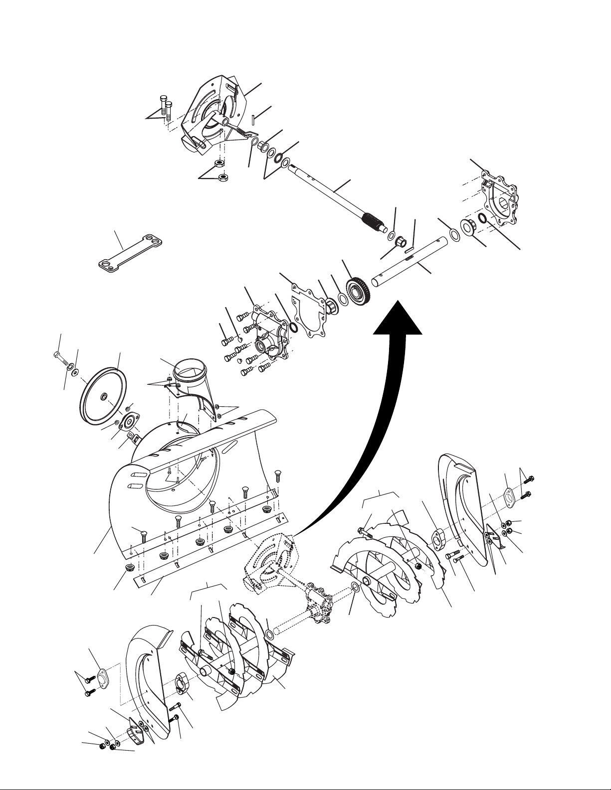
REPAIR PARTS AUGER HOUSING / IMPELLER ASSEMBLY
22
18
21
53
19
28
19
55
28
19
55
54
54
6
6
5
6
6
9
12
7
7
8
6
11
27
27
30
26
25
24
23
20
31
25
24
26
23
29
21
53
19
20
18
10
13
4
14
16
15
36
37
50
47
42
44
27
43
46
38
45
27
43
42
41
40
39
34
32
49
19
48
51
33
35
56
SNOW THROWER - MODEL NO. 10530SBE (96195000101), PRODUCT NO. 961 95 00-01
20
Page 2

REPAIR PARTS AUGER HOUSING / IMPELLER ASSEMBLY
SNOW THROWER - MODEL NO. 10530SBE (96195000101), PRODUCT NO. 961 95 00-01
KEY PART
NO. NO. DESCRIPTION
4 532 19 10-79 Pulley, Impeller
5 532 18 89-09 Bearing Assembly, Flange
6 532 15 53-77 Nut, Hex Flange 5/16-18
7 532 18 03-55 Bolt, Flat Head, Carriage 5/16-18 x 5/8
8 872 27 05-05 Bolt, Carriage 5/16-1 8 x 5/8
9 532 17 88-20 Nut, Cage 3/8-16
10 532 18 81-91 Housing, Auger
11 532 18 40-98 Bar, Scraper
12 532 18 40-95 Bracket, Corner Discharge
13 532 17 53-22 Base, Discharge Chute
14 819 11 15-07 Washer, Flat
15 810 04 05-00 Washer, Lock 5/16
16 874 95 05-12 Screw, Hex Head 5/16-18 x 3/4
18 532 17 95-82 Screw, Hex Head 5/16 x 1
19 873 80 04-00 Nut, Hex Lock 1/4-20
20 873 80 05-00 Nut, Hex Lock 5/16-18
21 532 15 54-15 Washer, Flat 5/16
22 532 18 40-94 Skid Plate, RH
23 532 17 92-46 Washer, Nylon, Friction
24 872 27 05-06 Bolt, Carriage 5/16-18 x 3/4
25 532 18 56-00 Bolt, Shoulder 1/4-20
26 532 18 81-70 Bearing Retainer, Plastic
27 532 17 46-97 Washer, Thrust, 1"
28 532 19 20-90 Bolt, Shear
29 532 18 40-93 Skid Plate, LH
30 532 19 95-30 Auger Assembly, RH
31 532 19 95-29 Auger Assembly, LH
32 532 17 46-99 O-Ring
33 532 17 47-00 Bushing, Flange 3/4
34 532 17 46-81 Washer, Thrust 3/4
35 532 17 46-84 Bearing, Thrust 3/4
36 532 17 46-60 Shaft, Impeller
37 532 17 46-83 Washer, Thrust 5/8
38 532 17 46-86 Bushing, Flange 5/8
39 532 15 00-78 Screw, Hex Head 5/16-18 x 3/4
40 532 08 64-47 Plug, Case
41 532 17 46-88 Housing, Gearbox, RH
42 532 17 46-98 Seal, Oil
43 532 17 47-01 Bushing, Flange, 1"
44 532 18 92-82 Key, Square 1/4 x 1/4 x 7/8
45 532 17 46-59 Gear, Worm
46 532 17 46-57 Shaft, Auger
47 532 17 46-87 Housing, Gearbox, LH
48 532 18 41-05 Impeller Assembly
49 874 78 04-26 Screw, Hex Head 1/4-20 x 1-5/8
50 532 17 53-11 Gasket, Gearbox
51 532 18 42-05 Pin, Roll 3/16 x 1-1/8
53 532 18 79-25 Bearing, Auger
54 532 05 38-47 Washer, Flat 1/4
55 532 18 82-43 Kit, Shear (Contains 6 each of Key Numbers 19 and 28)
56 532 18 06-84 Multi-Wrench
NOTE: All component dimensions given in U.S. inches. 1 inch = 25.4 mm
IMPORTANT: Use only Original Equipment Manufacturer (O.E.M.) replacement parts.
Failure to do so could be hazardous, damage your lawn mower and void your warranty.
21
Page 3
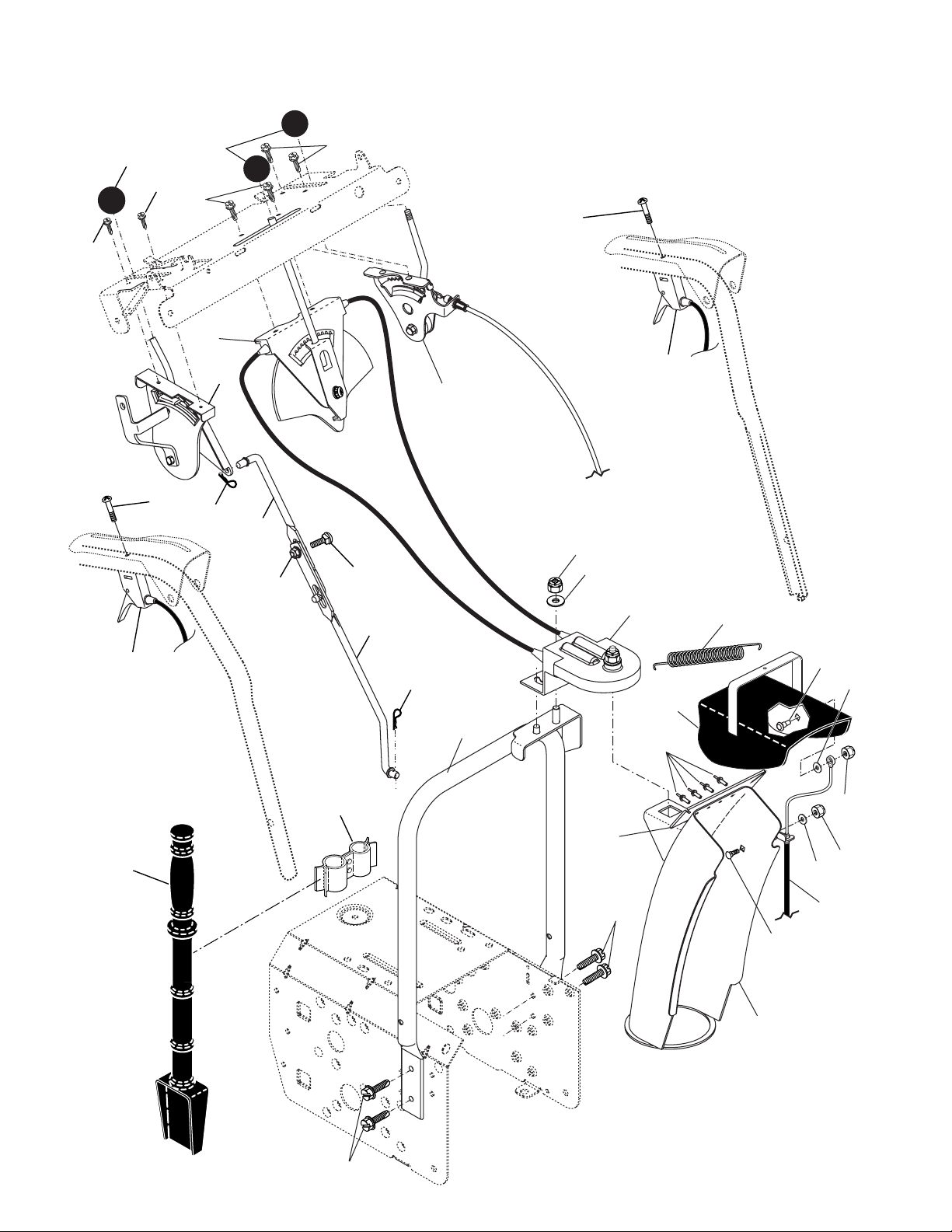
REPAIR PARTS CONTROL PANEL / DISCHARGE CHUTE
SNOW THROWER - MODEL NO. 10530SBE (96195000101), PRODUCT NO. 961 95 00-01
19
2
2
22
1
2
6
26
27
28
25
2
22
23
3
4
20
29
5
6
9
31
23
30
27
10
11
16
7
17
18
12
14
21
8
13
15
3
8
22
Page 4

REPAIR PARTS CONTROL PANEL / DISCHARGE CHUTE
SNOW THROWER - MODEL NO. 10530SBE (96195000101), PRODUCT NO. 961 95 00-01
KEY PART
NO. NO. DESCRIPTION
1 532 18 33-34 Knob, Lever
2 817 50 10-10 Screw #10-24 x 5/8
3 532 17 86-74 Control Assembly, Defl ector
4 873 80 06-00 Nut, Lock 3/8-16
5 819 13 13-16 Washer, Flat 3/8
6 532 17 86-59 Control Assembly, Chute Rotater
7 532 18 40-89 Support, Pivot
8 532 15 00-78 Screw, Hex Head 5/16-18 x 3/4
9 532 18 45-05 Spring, Defl ector
10 532 17 98-29 Bolt, Shoulder
11 532 17 92-46 Washer, Flat 1/4
12 873 80 04-00 Nut, Lock 1/4-20
13 872 25 05-05 Bolt, Carriage 5/16-18
14 873 80 05-00 Nut, Lock 5/16-18
15 532 18 41-12 Chute Assembly
16 532 18 41-13 Defl ector Assembly
17 532 17 91-45 Seal, Defl ector
18 532 12 84-15 Rivet, Blind
19 532 18 33-33 Knob, Speed Control Lever
20 872 27 05-06 Bolt, Carriage 5/16-18 x 3/4
21 532 15 54-15 Washer, Flat 5/16
22 874 04 10-24 Screw #10-24 x 1-1/2
23 532 19 24-49 Control Assembly, Power Steering
25 532 15 53-77 Nut, Lock 5/16-18
26 532 19 88-75 Lever Assembly, Speed Control
27 532 16 96-75 Retainer, Hairpin
28 532 18 04-45 Rod, Upper, Speed Control
29 532 18 77-16 Rod, Lower, Speed Control
30 532 19 27-10 Clamp, Clean-Out Tool
31 532 19 21-99 Tool, Clean-Out
NOTE: All component dimensions given in U.S. inches. 1 inch = 25.4 mm
IMPORTANT: Use only Original Equipment Manufacturer (O.E.M.) replacement parts.
Failure to do so could be hazardous, damage your lawn mower and void your warranty.
23
Page 5

REPAIR PARTS HANDLES
SNOW THROWER - MODEL NO. 10530SBE (96195000101), PRODUCT NO. 961 95 00-01
2
3
7
6
5
8
1
3
5
28
34
4
46
44
4
43
15
33
35
10
15
34
46
11
5
42
45
28
4
36
9
37
15
35
18
21
22
5
4
12
15
13
11
19
17
16
22
32
31
12
17
16
14
31
23
20
24
25
27
24
32
26
27
30
40
38
39
24
41
Page 6

REPAIR PARTS HANDLES
SNOW THROWER - MODEL NO. 10530SBE (96195000101), PRODUCT NO. 961 95 00-01
KEY PART
NO. NO. DESCRIPTION
1 532 18 41-10 Lever, Auger Control, RH
2 532 18 41-09 Lever, Traction Drive Control, LH
3 532 19 96-39 Nut, Cage 1/4-20
4 532 17 88-88 Bushing, Flange
5 532 16 96-75 Retainer, Hairpin
6 532 19 96-40 Screw, Hex Head
7 532 17 86-52 Rod, Interlock
8 532 19 95-76 Arm, Impeller Rod
9 532 19 95-75 Arm, Traction Rod
10 532 19 95-31 Panel, Control
11 874 78 05-24 Screw, Hex Head 5/16-18 x 1-1/2
12 874 78 05-28 Screw, Hex Head 5/16-18 x 1-3/4
13 532 18 41-07 Handle Tube, LH
14 532 18 41-08 Handle Tube, RH
15 873 80 05-00 Nut, Lock 5/16-18
16 819 13 13-16 Washer, Flat 3/8
17 532 17 88-99 Knob, Handle
18 532 18 45-94 Rod, Auger Control
19 532 19 30-81 Rod, Traction Control
20 532 18 04-28 End, Control Rod
21 873 35 05-00 Nut, Hex, Jam 5/16-18
22 872 12 06-18 Bolt, Carriage 3/8-16 x 2-1/4
23 532 18 40-87 Handle Tube, Lower
24 532 18 04-47 Sleeve, Spring
25 532 18 09-26 Spring, Traction Drive
26 532 17 86-69 Spring, Auger Control
27 871 21 06-16 Screw, Hex Head 3/8-16 x 1
28 532 17 53-31 Bushing, Pivot Lever
30 532 18 29-06 Console, Panel
31 532 17 52-62 Screw, Hex Head, Tapping #10-24 x 1-1/4
32 532 18 44-71 Screw, Hex Head, Tapping #10-24 x 1/2
33 532 19 95-77 Latch, Interlock
34 532 18 35-18 Bolt, Shoulder
35 532 06 80-38 Nut, Lock 1/4-20
36 532 17 88-31 Spring, Torsion
37 532 19 38-85 Spring, Interlock
38 532 17 86-66 Headlight, Halogen (Includes Bulb)
- - 532 40 16-20 Bulb, Halogen
39 532 17 86-68 Bezel, Headlight
40 532 18 09-64 Harness, Headlight (Halogen)
41 532 17 88-90 Nut, Cage 3/8-16
42 532 19 95-78 Lever, Interlock
43 532 19 96-38 Rod, Latch, Interlock
44 532 19 63-38 Rod, Arm, Interlock
45 532 70 02-79 Clip
46 532 17 92-46 Washer, Friction
NOTE: All component dimensions given in U.S. inches. 1 inch = 25.4 mm
IMPORTANT: Use only Original Equipment Manufacturer (O.E.M.) replacement parts.
Failure to do so could be hazardous, damage your lawn mower and void your warranty.
25
Page 7

REPAIR PARTS DRIVE
SNOW THROWER - MODEL NO. 10530SBE (96195000101), PRODUCT NO. 961 95 00-01
5
2
3
23
15
41
1
4
2
42
7
8
10
9
5
4
3
2
4
2
3
24
5
1
27
2
42
7
6
19
3
4
1
3
2
5
4
1
2
14
13
16
21
20
18
17
18
22
12
32
44
26
26
28
31
30
22
15
25
29
35
22
41
33
33
11
43
34
36
38
39
40
37
Page 8

REPAIR PARTS DRIVE
SNOW THROWER - MODEL NO. 10530SBE (96195000101), PRODUCT NO. 961 95 00-01
KEY PART
NO. NO. DESCRIPTION
1 532 14 63-15 Screw, Hex Head 5/16-18 x 3/4
2 873 80 05-00 Nut, Lock 5/16-18
3 532 15 54-15 Washer, Flat
4 817 49 05-08 Screw, Hex Head 5/16-18 x 1/2
5 532 18 00-17 Bearing, Flange
6 532 18 01-34 Shaft, Auxiliary
7 532 17 92-70 Spacer, Plate
8 532 19 29-07 Plate, Auxiliary
9 532 18 00-82 Gear, Intermediate (12/58)
10 532 18 00-65 Gear, Pinion
11 532 18 77-14 Rod, Clutch
12 532 18 00-66 Shaft, Long, Hex
13 532 17 88-07 Pin, Pivot
14 532 18 40-80 Lever, Shifter / Wheel
15 532 17 53-44 Trunnion Bearing Assembly
16 532 18 78-57 Bracket, Pivot, Shift
17 532 17 98-31 Ring, Rubber Wheel
18 532 19 95-09 Plate, Rubber Wheel
19 873 93 05-00 Nut, Lock 5/16-18
20 532 17 86-13 Hub, Rubber Wheel
21 874 76 05-14 Screw, Hex Head 5/16-18 x 7/8
22 532 08 51-79 Retainer, Hairpin
23 532 18 01-35 Spring, Bias
24 532 18 00-81 Gear, Axle (58 Teeth)
25 532 17 86-95 Pin, Pivot Lever
26 532 19 77-63 Plate Assembly, Drive
27 532 17 86-21 Shaft, Axle
28 532 19 77-64 Shaft, Short Hex
29 532 18 40-77 Lever, Shifter Plate
30 532 18 40-76 Bracket, Shifter Support
31 872 27 05-05 Bolt, Carriage 5/16-18 x 5/8
32 532 18 92-82 Key, Square
33 532 18 89-09 Bearing, Flange
34 532 18 40-75 Plate, Drive Mounting
35 532 18 25-04 Spacer, Bearing
36 532 19 10-80 Pulley, Traction Drive
37 532 15 53-77 Nut, Lock 5/16-18
38 819 11 15-07 Washer, Flat
39 810 04 05-00 Washer, Lock 5/16
40 874 95 05-12 Screw, Hex Head 5/16-18 x 3/4
41 812 00 00-12 Ring, Retaining
42 811 05 05-00 Washer, Lock, External Tooth 5/16
43 532 17 90-95 Spring, Return
44 532 18 42-06 Pin, Roll
NOTE: All component dimensions given in U.S. inches. 1 inch = 25.4 mm
IMPORTANT: Use only Original Equipment Manufacturer (O.E.M.) replacement parts.
Failure to do so could be hazardous, damage your lawn mower and void your warranty.
27
Page 9

REPAIR PARTS CHASSIS / ENGINE / PULLEYS
SNOW THROWER - MODEL NO. 10530SBE (96195000101), PRODUCT NO. 961 95 00-01
32
34
41
31
36
33
30
37
3
58
23
20
57
13
28
6
10
21
24
25
26
27
7
6
15
19
17
6
22
4
31
10
21
29
16
2
6
1
39
43
42
11
54
44
12
8
14
45
55
6
38
41
7
9
18
35
50
52
51
11
53
11
46
40
44
49
48
47
47
28
Page 10

REPAIR PARTS CHASSIS / ENGINE / PULLEYS
SNOW THROWER - MODEL NO. 10530SBE (96195000101), PRODUCT NO. 961 95 00-01
KEY PART
NO. NO. DESCRIPTION
1 532 18 10-44 Spring, Traction Idler
2 532 18 05-22 Pulley, Idler (2-1/4)
3 - - - Engine, Tecumseh, Model Number
LH358SA (For engine service and
replacement parts, call Tecumseh
Products at 1-800-558-5402)
4 874 78 05-20 Screw, Hex Head 5/16-18 x 1-1/4
6 532 05 92-89 Washer, Flat
7 873 93 05-00 Nut, Jam, Lock 5/16-18
8 532 17 53-30 Pin, Idler Pivot
9 532 17 90-92 V-Belt, Traction Drive
10 810 04 05-00 Washer, Lock 5/16
11 817 49 05-08 Screw, Hex Head 5/16-18 x 1/2
12 532 17 92-59 Impeller Arm / Pad Assembly
13 532 08 51-79 Retainer, Hairpin
14 532 17 88-28 Spring, Brake
15 532 18 35-33 V-Belt, Impeller Drive
16 532 19 23-06 Screw, Hex Head 3/8-16 x 1-1/4
17 532 18 48-04 Arm, Idler
18 874 78 05-24 Screw, Hex Head 5/16-18 x 1-1/2
19 532 17 53-31 Bushing, Idler Pivot
20 532 18 05-23 Pulley, Idler (2-3/4)
21 874 61 05-16 Screw, Hex Head 5/16-18 x 1
22 532 17 93-71 Spacer, Engine Pulley
23 532 18 04-78 Pulley, Engine, Traction Drive
24 532 17 91-57 Pulley, Engine, Impeller Drive
25 532 06 27-35 Washer, Flat 3/8
26 532 85 02-63 Washer, Lock, Helical 3/8
27 532 85 10-84 Screw, Hex Head 3/8-24 x 1-3/8
28 532 15 54-52 Guide, Belt
KEY PART
NO. NO. DESCRIPTION
29 532 19 22-13 Belt Cover Assembly
(Includes Toolbox Cover)
30 532 17 88-30 Cover, Toolbox
31 817 49 04-08 Screw, Hex Head 1/4-20 x 1/2
32 532 17 92-56 Bolt, Shoulder 5/16-18
33 532 18 78-53 Bellcrank Shifter
34 532 18 04-01 Screw, Hex Head 1/4-28 x 3/4
35 532 19 57-67 Arm, Auger Control
36 873 80 05-00 Nut, Lock 5/16-18
37 532 18 40-86 Bellcrank
38 532 18 71-01 Link, Speed Control
39 532 19 21-10 Trunnion, Pivot Bracket
40 532 17 88-90 Nut, Cage 3/8-16
41 532 70 02-79 Hairpin, Cotter 3/32 x 1/2
42 532 17 90-65 Pin, Pivot Bracket
43 532 18 40-85 Bracket, Bellcrank
44 871 21 06-16 Screw, Hex Head
45 532 18 40-74 Pivot Bracket, Impeller Idler Arm
46 532 18 40-84 Pan, Frame Bottom
47 871 02 05-12 Screw, Hex Head 5/16-18 x 3/4
48 532 18 11-56 Nut, Speed 5/16-18
49 532 18 40-73 Frame Assembly
50 532 18 80-02 Plate, Frame End
51 532 19 95-14 Shaft, Auger Control
52 532 05 70-79 Washer, Hardened
53 532 19 22-75 Roller
54 532 19 21-47 Ring, Crescent
55 812 00 00-02 E-Ring
57 811 05 05-00 Washer, Lock, External Tooth 5/16
58 532 18 38-54 Power Cord
NOTE: All component dimensions given in U.S. inches. 1 inch = 25.4 mm
IMPORTANT: Use only Original Equipment Manufacturer (O.E.M.) replacement parts.
Failure to do so could be hazardous, damage your lawn mower and void your warranty.
29
Page 11

REPAIR PARTS WHEELS / DECALS
SNOW THROWER - MODEL NO. 10530SBE (96195000101), PRODUCT NO. 961 95 00-01
31
18
10
30
15
32
12
34
7
4
8
28
25
26
34
9
22
24
23
33
21
3
4
10
17
19
28
29
34
4
13
14
27
20
11
2
10
16
19
2
18
34
30
15
12
34
29
14
28
27
13
32
1
13
2
20
4
25
11
24
28
34
26
23
33
21
22
3
12
4
9
1
8
113
6
5
11
10
3
30
7
Page 12

REPAIR PARTS WHEELS / DECALS
SNOW THROWER - MODEL NO. 10530SBE (96195000101), PRODUCT NO. 961 95 00-01
KEY PART
NO. NO. DESCRIPTION
1 532 19 95-01 Wheel Assembly, 16", Power Steering, LH
2 532 15 54-43 Pin, Klik 1/4
3 532 19 21-09 Cover, Power Steering
4 532 18 44-71 Bolt, Shoulder #10-24 x 5/8
7 871 21 06-16 Capscrew, Hex Head, Flanged 3/8-16 x 1
8 532 18 78-59 Bracket, Steering Cable, RH
9 532 18 78-58 Bracket, Steering Cable, LH
10 817 60 04-06 Screw, Hex Head 1/4-20 x 3/8
11 817 49 05-08 Screw, Hex Head 5/16-18 x 1/2
12 532 19 57-49 Link, Steering Lever
13 532 18 78-60 Yoke, Steering
14 532 18 20-15 Pin, Steering Lever
15 532 19 95-18 Bellcrank
16 532 19 95-12 Bracket Assembly, LH Steering
17 532 19 95-11 Bracket Assembly, RH Steering
18 532 18 18-47 Pin, Steering Bellcrank
19 532 08 51-79 Retainer, Hairpin
20 532 18 41-97 Bracket, Steering
21 532 19 21-26 Driver, Wheel
22 532 18 24-66 Ring, Wire Retainer
23 532 18 76-22 Lobe, Wheel
24 532 19 49-41 Slide, Clutch
25 532 17 91-39 Spring, Clutch Slide
26 532 19 49-40 Lobe, Axle
27 532 18 92-82 Key, Square
28 532 17 46-97 Washer, Thrust (1")
29 532 17 98-30 Bearing, Axle
30 532 19 38-85 Spring, Return
31 532 19 95-20 Wheel Assembly, 16", Power Steering, RH
32 532 70 02-79 Clip, Retainer
33 812 00 00-45 Ring, Retaining
34 532 14 63-15 Screw, Hex Head 5/16-18 x 5/8
KEY PART
NO. NO. DESCRIPTION
1 532 18 10-38 Decal, Danger
2 532 19 13-78 Decal, Husqvarna
3 532 18 10-34 Decal, Danger, Defl ector
4 532 18 10-41 Decal, Danger
5 532 19 87-38 Decal, Husqvarna, 10530SB
6 532 18 10-32 Decal, Instruction
7 532 15 57-98 Decal, Traction Lever
8 532 15 58-00 Decal, Auger Lever
9 532 18 10-36 Decal, Speed Control
10 532 18 37-29 Decal, Remote Defl ector
11 532 18 39-07 Decal, LH Trigger
12 532 18 39-05 Decal, RH Trigger
13 532 15 57-94 Decal, Husqvarna, Crown
- - 532 19 15-54 Decal, Lowe's Service (not shown)
- - 532 40 03-22 Owner’s Manual
NOTE: All component dimensions given in U.S. inches. 1 inch = 25.4 mm
IMPORTANT: Use only Original Equipment Manufacturer (O.E.M.) replacement parts.
Failure to do so could be hazardous, damage your lawn mower and void your warranty.
31
 Loading...