

Page 1
Owner’s Manual
Snow Thrower
5.5 Horsepower
Dual Stage
Model 96194000200
CAUTION: Before using this product, read this
manual and follow all of its Safety Rules and
Operating Instructions.
Manual del usario
Quitanieves
5.5caballosdefuerza(hp)
Bietápico
Modelo 96194000200
PRECAUCIÓN: Antes de usar este producto, lea este
manual y siga todas las reglas de seguridad e
instrucciones de operación.
406885 09/01/06
Printed in U.S.A
1
Page 2
1
1
5
21
6
14
9
13
10
11
8
12
16
15
2
3
22
4
21
17
19
7
2
Page 3
GENERAL INFORMATION
This instruction book is written for a person with some mechanical ability.
Like most service books, not all the steps are described. Steps on how to
loosen or tighten fasteners are steps anyone can follow with some
mechanical ability. Read and follow these instructions before you use the
unit.
Know your product: If you understand the unit and how the unit
operates, y ou will get the best performance. As you read this manual,
compare the illustrations to the unit. Learn the location and the function of
the c ontrols. To help prevent an accident, follow the operating instructions
and the safety rules. Keep this manual for future reference.
IMPORTANT: Many units are not assembled and are s old in cartons. It is
the responsibility of the owner to make sure the assembly instructions in
this manual are exactly followed. Other units are purchased in an
assembled condition. On assembled units, it is the responsibility of the
owner to make sure the unit is correctly assembled. The owner must
carefully check the unit according to the instructions in this manual before
it is first used.
Declared vibration emission values in accordance with Directive 98/37/EC.
Vibration Emission according to EN 1033;1996: 2,5
Values determined at the handle when the machine was operated stationary on a
concrete surface at 3700 min--1.
GB
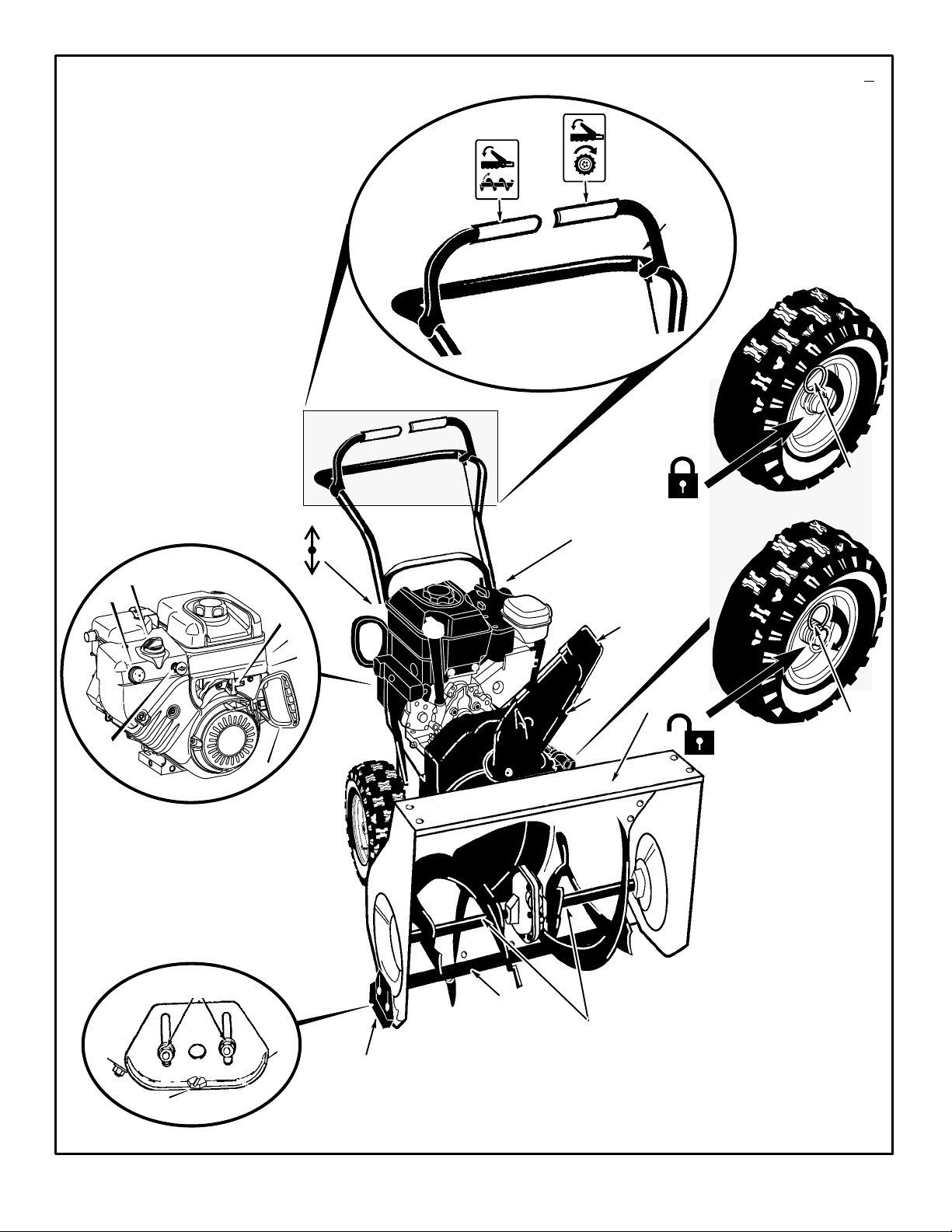
Controls & Equipment Features (see Figure 1)
Crank Assembly (2) -- Changes the direction of the discharge chute.
Chute Deflector (3) -- Changes the distance the snow is thrown.
Discharge Chute (4) -- Changes the direction the snow is thrown.
Auger Drive Lever (5) -- Starts and stops the auger (snow gathering and
throwing) which also propels the snowthrower..
Engine Features
Stop Switch (8) -- If equipped, move to the ON position to s tart the
engine.
Primer Button (9) -- Injects fuel directly into the carburetor for fast starts
in cold weather.
Recoil Starter Handle (12) -- Use to manually start the engine.
Choke C ontrol (14) -- Use to start a cold engine.
m/s2.
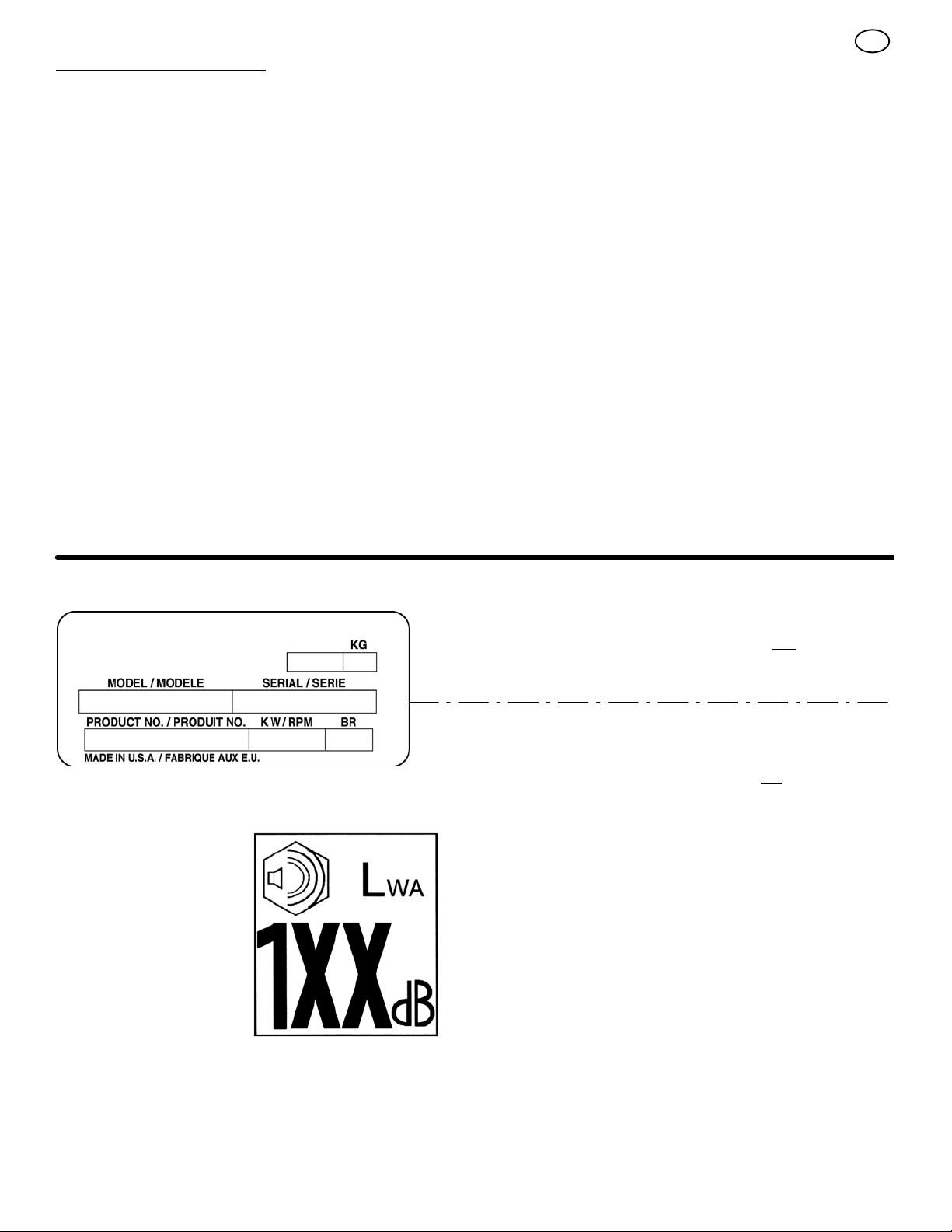
Declared airborne noise emissions of Lw
2000/14/EC, Annex V.
Sound Pressure Level at operator position 89 dB.
Values determined at ear according to the specifications of EN ISO 11201.
Declared airborne sound
power level of 108 dB(A) is in
accordance with Directive
2000/14/EC.
A 108 dB is in accordance with Directive
3
Page 4
This manual contains safety information to make you
aware of the hazards and risks associated with snow
throwers, and how to avoid them. The snow thrower is designed and
intended for removal of snow, and should not be used for any other
purpose. It is important that you read and understand these
instructions, and anyone operating the equipment read and understand
these instructions.
GB
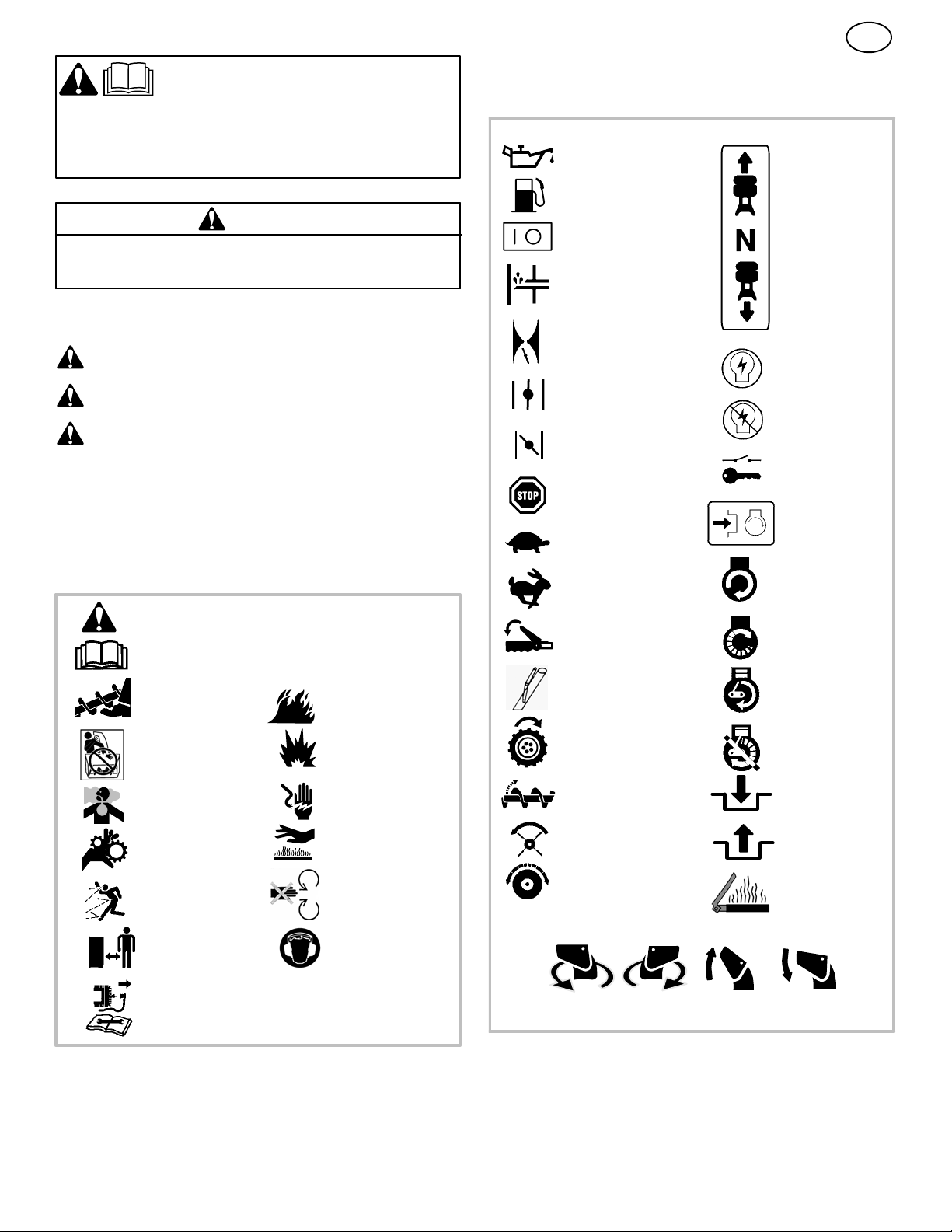
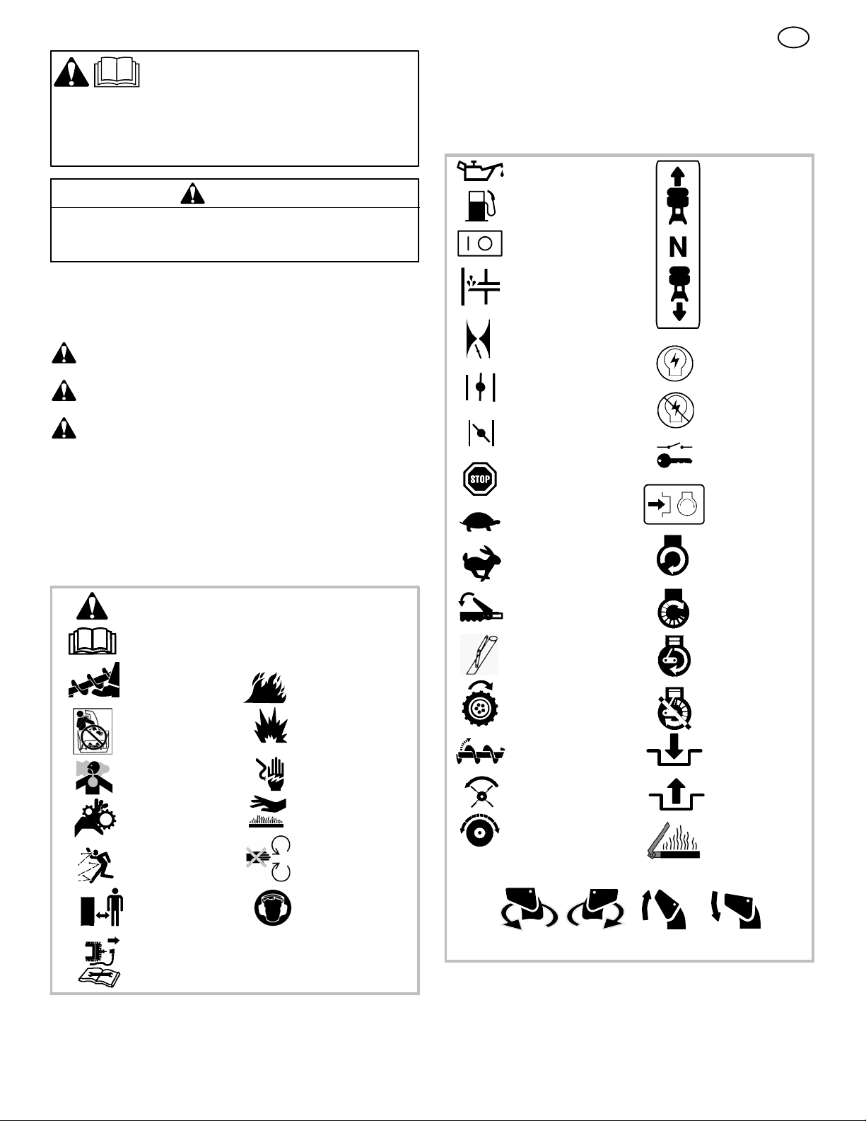
Operating Symbols and their meanings
These symbols are used on your equipment and defined in your operating
manual. It is important that you review and understand the meanings.
Failure to understand the symbols might result in harm to you.
Oil
WARNING
The engine exhaust from this product contains chemicals known to the
State of California to cause cancer, birth defects, or other reproductive
harm.
A signal word (DANGER, WARNING, or CAUTION) is used with the alert
symbol to indicate the likelihood and the potential severity of injury. In
addition, a hazard symbol may be used to represent the type of hazard.
DANGER indicates a hazard which, if not avoided, will result in
death or serious injury.
WARNING indicates a hazard which, if not avoided, could result
in death or serious injury.
CAUTION indicates a hazard which, if not avoided, might result
in minor or moderate injury.
CAUTION, when used without the alert symbol, indicates a
situation that could result in damage to the equipment.
Hazard Symbols and the meanings
These symbols are used on your equipment and defined in your operating
manual. Review and understand the meanings. The use of one of these
symbols combined with a signal word will alert you to potential hazards
and how to avoid them.
Safety Alert -- Identifies safety information about
hazards that can result in personal injury.
Operator’s Manual -- Read and understand before
performing any activity or running equipment.
Fuel
On Off
Primer bulb
Throttle
Choke off
Choke on
Stop
Slow
Fast
Engage
Foward
Neutral
Reverse
Ignition On
Ignition Off
Ignition Key
Push to engage
electric start
Electric
Start
Engine
Start
Rotating auger
Rotating impeller
Toxic fumes
Rotating gears
Thrown objects
Keep a safe distance
from the equipment.
Shut off engine and remove spark plug connector
before performing maintenance or repair work.
Fire
Explosion
Shock
Hot Surface
Never reach into
rotating parts.
Recommended ear
protection for extended
use.
Engage
Traction
Auger Collector
Auger Clutch
Drive Clutch
Discharge Chute
LEFT UP
RIGHT
Chute Deflector
Engine Run
Engine Off
Engage
Disengage
Heated Grips
DOWN
4
Page 5

WARNING: This machine is capable ofto amputating hands and feet and throwing objects. Read these safety rules
and follow them closely. Failure to obey these rules could result in loss of control of unit, severe personal injury or
death to you, or bystanders, or damage to property or equipment. The triangle in text signifies important cautions or warnings which must be followed.
Safe Operation Practices for Snowthrowers
IMPORTANT: Safety standards require operator presence controls to
minimize the risk of injury. Your snowthrower is equipped with such controls. Do not attempt to defeat the function of the operator presence control under any circumstances.
Training
1. Read, understand, and follow all instructions on the machine and in the
manuals before operating this unit. Be thoroughly familiar with the controls and the proper use of the equipment. Know how to stop the unit
and disengage the controls quickly.
2. Never allow children to operate the equipment. Never allow adults to
operate the equipment without proper instruction.
3. Keep the area of operation clear of all persons, particularly small
children and pets.
4. Exercise caution to avoid slipping or falling especially when operating in
reverse.
Preparation
1. Thoroughly inspect the area where the equipment is to be used and
remove all doormats, sleds, boards, wires, and other foreign objects.
2. Disengage all clutches and shift into neutral before starting the engine
(motor).
3. Do not operate the equipment without wearing adequate winter outer
garments. Wear footwear that will improve footing on slippery surfaces.
Avoid loose fitting clothing that can get caught in moving parts.
4. Handle fuel with care; it is highly flammable.
a. Use an approved fuel container.
b. Never add fuel to a running engine or hot engine.
c. Fill fuel tank outdoors with extreme care. Never fill fuel tank indoors.
Replace fuel cap securely and wipe up spilled fuel.
d. Never fill containers inside a vehicle or on a truck or trailer bed with
a plastic liner. Always place containers on the ground, away from
your vehicle, before filling.
e. When practical, remove gas--powered equipment from the truck or
trailer and refuel it on the ground. If this is not possible, then refuel
such on a trailer with a portable container, rather than from a gasoline dispenser nozzle.
f. Keep nozzle in contact with the rim of the fuel tank or container
opening at all times, until refueling is complete. Do not use a nozzle
lock--open device.
g. Replace gasoline cap securely and wipe up spilled fuel.
h. If fuel is spilled on clothing, change clothing immediately.
5. Use extension cords and receptacles as specified by the manufacturer for all units with electric drive motors or electric starting motors.
6. Adjust the collector housing height to clear gravel or crushed rock
surfaces.
7. Never attempt to make any adjustments while the engine (motor) is
running (except when specifically recommended by manufacturer).
8. Let engine (motor) and snowthrower adjust to outdoor temperatures
before starting to clear snow.
9. Always wear safety glasses or eye shields during operation or while
performing an adjustment or repair to protect eyes from foreign objects
that may be thrown from the machine.
GB
Operation
1. Do not put hands or feet near or under rotating parts. Keep clear of the
discharge opening at all times.
2. Exercise extreme caution when operating on or crossing gravel drives,
walks or roads. Stay alert for hidden hazards or traffic.
3. After striking a foreign object, stop the engine (motor), remove the wire
from the spark plug, disconnect the cord on electric motors, thoroughly
inspect snowthrower for any damage, and repair the damage before
restarting and operating the snowthrower.
4. If the unit should start to vibrate abnormally, stop the engine (motor)
and check immediately for the cause. Vibration is generally a warning
of trouble.
5. Stop the engine (motor) whenever you leave the operating position,
before unclogging the collector/impeller housing or discharge chute and
when making any repairs, adjustments, or inspections.
6. When cleaning, repairing, or inspecting, make certain the collector/impeller and all moving parts have stopped. Disconnect the spark plug
wire and keep the wire away from the spark plug to prevent accidental
starting.
7. Do not run the engine indoors, except when starting the engine and for
transporting the snowthrower in or out of the building. Open the outside
doors; exhaust fumes are dangerous (containing CARBON MONOXIDE, an ODORLESS and DEADLY GAS).
8. Exercise extreme caution when operating on slopes. Do not attempt to
clear steep slopes.
9. Never operate the snowthrower without proper guards, plates, or other
safety protective devices in place and working.
10. Never direct the discharge toward people or areas where property
damage can occur. Keep children and others away.
11. Do not overload the machine capacity by attempting to clear snow at
too fast a rate.
12. Never operate the machine at high transport speeds on slippery surfaces. Look behind and use care when operating in reverse.
13. Disengage power to the collector/impeller when snowthrower is transported or not in use.
14. Use only attachments and accessories approved by the manufacturer
of the snowthrower (such as cabs, tire chains, etc..).
15. Never operate the snowthrower without good visibility or light. Always
be sure of your footing and keep a firm hold on the handles. Walk,
never run.
16. Never touch a hot engine or muffler.
17. Never operate the snowthrower near glass enclosures, automobiles,
window wells, drop--offs, and the like without proper adjustment of the
snow discharge angle.
18. Never direct discharge at bystanders or allow anyone in front of the
unit.
19. Never leave a running unit unattended. Always disengage the auger
and traction controls, stop engine, and remove keys.
20. Do not operate the unit while under the influence of alcohol or drugs.
21. Keep in mind the operator is responsible for accidents occurring to
other people or property.
22. Data indicates that operators, age 60 years and above, are involved
in a large percentage of power equipment--related injuries. These
operators should evaluate their ability to operate the unit safely
enough to protect themselves and others from injury.
23. DO NOT wear long scarves or loose clothing that could become
entangled in moving parts.
24. Snow can hide obstacles. Make sure to remove all obstacles from
theareatobecleared.
5
Page 6

Children
Tragic accidents can occur if the operator is not alert to the presence of children. Children are often attracted to the unit and the operating activity. Never
assume that children will remain where you last saw them.
1. Keep children out of the area and under the watchful care of another
responsible adult.
2. Be alert and turn off if children enter the area.
3. Never allow children to operate the unit.
4. Use extra care when approaching blind corners, shrubs, trees, or
other objects that may obscure vision.
Clearing A Clogged Discharge Chute
Hand contact with the rotating impeller inside the discharge chute is the
most common cause of injury associated with snowthrowers. Never use
your hand to clean out the discharge chute.
To clear the chute:
1. SHUT OFF THE ENGINE.
2. Wait 10 seconds to be sure the impeller blades have stopped rotating.
3. Always use a clean out tool, not your hands.
Service, Maintenance And Storage
1. Check shear bolts and other bolts at frequent intervals for proper tightness to be sure the equipment is in safe working condition.
2. Never store the machine with fuel in the tank inside a building where
ignition sources are present such as hot water and space heaters, or
clothes dryers. Allow the engine to cool before storing in any enclosure.
3. Always refer to operator’s manual for important details if the snowthrower is to be stored for an extended period.
4. Maintain or replace safety and instruction labels as necessary.
5. Run the machine a few minutes after throwing snow to prevent freeze-up of the collector/impeller.
6. If fuel is spilled, do not attempt to start the engine but move the machine away from the area of spillage and avoid creating any source of
ignition until fuel vapors have dissipated.
GB
7. Always observe safe refueling and fuel handling practices when refueling the unit after transportation or storage.
8. Always follow the engine’s manual instructions for storage preparations
before storing the unit for both short and long term periods,
9. Always follow the engine manual instructions for proper start-up procedures when returning the unit to service.
10. Maintain or replace safety and instruction labels as necessary.
11. Keep nuts and bolts tight and keep equipment in good condition.
12. Never tamper with safety devices. Check their proper operation regularly and make necessary repairs if they are not functioning properly.
13. Components are subject to wear, damage, and deterioration. Frequently check components and replace with manufacturer’s recommended
parts, when necessary.
14. Check control operation frequently. Adjust and service as required.
15. Use only factory authorized replacement parts when making repairs.
16. Always comply with factory specifications on all settings and adjustments.
17. Only authorized service locations should be utilized for major service
and repair requirements.
18. Never attempt to make major repairs on this unit unless you have been
properly trained. Improper service procedures can result in hazardous
operation, equipment damage and voiding of manufacturer’s warranty.
19. Check shear bolts (pins) and other bolts at frequent intervals for proper
tightness to be sure the equipment is in safe working condition.
Emissions
1. Engine exhaust from this product contains chemicals known, in certain
quantities, to cause cancer, birth defects, or reproductive harm.
2. If available, look for the relevant Emissions Durability Period and Air
Index information on the engine emissions label.
Ignition System
1. This spark ignition system complies with Canadian ICES-002.
6
Page 7
ASSEMBLY
Read and follow the assembly and adjustment
instructions for your snow thrower. All fasteners
are in the parts bag. Do not discard any parts or
material until the unit is assembled.
WARNING: Before doing any
assembly or maintenance to the
snow thrower, remove the wire
from the spark plug.
NOTE: In this instruction book, left and right
describe the location of a part from the operator’s position behind the unit.
NOTE: Torque is measured in foot pounds
(metric N.m). This measurement describes
how tight a nut or bolt must be. The torque is
measured with a torque wrench.
NOTE: Fasteners and loose parts are shown
at full size in Figure 2 on page 29.
NOTE: Illustrations are located on page 2
and on pages 30 through 35.
Tools Required
1Knife
1 Pliers
2 1/2 inch open end wrenches
2 9/16 inch open end wrenches
2 3/4 inch open end wrenches
1 Measuring tape or ruler
1 Screwdriver
How To Remove The Snow Thrower
From The Carton
1. (Figure 3) The snow thrower is shown in the
shipping position.
2. Cut and discard the plastic ties that secure
the c rank assembly and the speed control
rod assembly.
3. Cut down all four corners of the carton and
lay the side panels flat.
4. Locate all parts that are packed separately
and remove from the carton.
5. Remove and discard the packing material
from around the snow thrower.
6. (Figure 1) For shipping purposes, the height
adjust skids (7) are attached to the pallet.
Remove the screw (17) that secures each
height adjust skid (7) to the pallet.
7. Hold onto the lower handle and pull the snow
thrower off the pallet.
CAUTION: DO NOT back over cables.
8. Remove the packing material from the handle assembly.
9. Cut the ties that secure the clutch control
cables (1) to the lower handle (2). Move the
cables away from the motor frame.
How To Assemble The Handle And
Crank Assembly
1. (Figure 4) Loosen, but do not remove, the
fasteners (1) in the upper holes of the lower
handle.
2. Remove the fasteners and the crank assem-
bly eyebolt (11) from the lower holes of the
lower handle.
3. (Figure 1) Put the shift lever (6) into first
forward position.
4. (Figure 4) Raise the upper handle (2) to the
operating position.
NOTE: Make sure the cables are not
caught between the upper and lower handle.
5. Install the fasteners and the crank assembly
eyebolt (11) thatwereremovedinstep2.
DO NOT tighten until all fasteners are in
place.
6. (Figure 5) Attach the crank rod (15) to the
universal joint assembly (16) with the hair
pin (12).
7. (Figure 4) Tighten nut on eye bolt (11).
Make sure eye bolt (11) is properly aligned
and the crank (18) can freely rotate.
8. Tighten all handle fasteners.
How To Install The Knob(s) (Figure 6)
NOTE: If knob(s) are already installed, go to
the next selection.
1. Attach the knob (3) onto the speed shift lever (2). On some models, the knob (3) is
attached. To lock in position, tighten the hex
jam nut (1) against the bottom of the knob
(3).
2. Make sure the speed shift lever (2) functions correctly. Move the speed shift lever
(2) through all speeds.
How To Assemble The Chute Deflector
1. (Figure 4) Turn the crank assembly (18)
counterclockwise until crank assembly (18)
stops.
2. (Figure 7) Fasten chute deflector (2) to
flange (4) with carriage bolts (1). Make sure
to install with head of the carriage bolts (1)
on the inside of the flange (2).
3. Fasten with washers (5) and locknuts (6).
4. Tighten locknuts (6) securely.
NOTE: Make sure all carriage bolts in flange
are tight. DO NOT OVERTIGHTEN.
Check The Cables
1. (Figure 8) Check the traction drive cable
(1) and the auger drive cable (2). If the bot-
tom of the cables have become disconnected, reinstall the cables.
2. (Figure 10) If the top of the cables (5) have
become disconnected from the drive levers
(6), attach the cables (5) to the “Z” fitting
(7).
How To Set The Skid Height (Figure 1)
The snow thrower is equipped with height adjustable skids (7) mounted on the outside of the
auger housing (4). To adjust the height of the
skids, s ee “How To Adjust The Height Of The
Skids” in the Maintenance section.
7
GB
How To Set The Length Of The Cables
The cables were adjusted at the factory and no
adjustments should be necessary. However, after the handles are put in the operating position,
the c ables can be too tight or too loose. If an
adjustment is necessary, see “How To Check
And Adjust The Cables” in the Service And Adjustment section.
How To Assemble The Drift Cutter
(if equipped)
Drift cutters are used to cut a path through snow
deeper than the auger housing.
1. (Figure 11) Loosen the fasteners (2) that
secure the drift cutters (1) to the auger
housing.
2. Raise the drift cutters (1) to the desired
height.
3. Tighten the fasteners (2).
How To Prepare The Engine
NOTE: The engine was shipped from the
factory filled with oil. Check the level of the
oil. Add oil as needed.
WARNING: Follow the engine
manufacturer’s instructions for the
type of fuel and oil to use. Always
use a safety fuel container. Do not smoke
when adding gasoline to the engine. When
inside an enclosure, do not fill with gasoline. Before you add fuel, stop the engine.
Let the engine cool for several minutes.
Check the oil. See the engine manufacturer’s
instructions for the type of fuel and oil to use.
Before you use the unit, read the information on
safety, operation, maintenance, and storage.
Important! Before You Start Operating
U Check the fasteners. Make sure all fas-
teners are tight.
U On electric start models, the unit was
shipped with the starter cord plugged
into the engine. Before operating, unplug the starter cord from the engine.
OPERATION
NOTE: Illustrations are located on page 2
and on pages 30 through 35.
CAUTION: Use only attachments and accessories approved by the manufacturer of the
snow thrower (such as tire chains, electric
start kits, etc.).
Know Your Snow Thrower (Figure 1)
Read this Instruction Book and safety rules before operation the snow thrower. Compare the
illustration with your snow thrower to familiarize
yourself with the location of various controls and
adjustments.
How To Control
The Discharge Of The Snow
WARNING: Never direct the dis-
charge of snow toward bystanders.
WARNING: Always stop the engine
before unclogging the discharge
chute or the auger housing and before leaving the snow thrower.
Page 8
1. (Figure 1) Turn the crank assembly (2) to
change the discharge direction of the snow.
2. (Figure 12) Loosen the wing knob (1) on
the chute deflector (2) and move the chute
deflector (2) to set the distance. Move the
chute deflector (2) UP for more distance,
DOWN for less distance. Then tighten the
wing knob (1).
How To Stop
The Snow Thrower (Figure 1)
1. To stop discharging snow, release the auger
drive lever (5).
2. To stop the wheels, release the traction
drive lever (1).
3. To stop the engine, move the stop switch
(13) to the OFF position.
CAUTION: To stop the engine, do not move
the choke control to CHOKE position. Backfire or engine damage can occur.
How To Go Forward or Backward
(Figure 1)
1. To change the ground speed, first release the
traction drive lever (1) and then move the
speed shift lever (6) to the desired speed.
2. Ground speed is determined by snow conditions. Select the speed by moving the speed
shift lever (6) into the appropriate notch on
the s hift lever plate.
Speed 1, 2 Wet, Heavy
Speed 3 Light
Speed 4 Very Light
Speed 5, 6 Transport only
3. To go forward, engage the traction drive
lever (1). Maintain a firm hold on the handle
as the snow thrower starts to move forward.
Guide the snow thrower by moving the handle either left or right. Do not attempt to push
the snow thrower.
4. To go backward, release the tractor drive
lever (1).
5. Move the speed shift lever (6) into either
first or second reverse.
6. Engage the traction drive lever (1).
IMPORTANT: Do not move the speed shift
lever (6) while the traction drive lever (1) is
engaged.
How To Throw Snow (Figure 1)
1. Engage the auger drive lever (5).
2. To stop throwing snow, release the auger
drive lever (5).
WARNING: The operation of any
snow thrower can result in foreign
objects being thrown into the eyes,
which can result in severe eye damage.
Always wear safety glasses or eye shields
while operating the snow thrower. We recommend standard safety glasses or use a
wide vision safety mask over your glasses.
How To Use The Wheel Lockout Pin
(Figure 13)
1. The right hand wheel is secured to the axle
with a klick pin (1). This unit was shipped
with this klick pin (1) through the wheel hole
in the locked position (2).
2. For ease of maneuverability in light snow
conditions, c hange the klick pin (1) to an
unlocked position (3).
3. Disconnect the klick pin (1) from the wheel
locked position (2). Push the klick pin (1)
through the unlocked axle hole only. The unit
is now in the single wheel drive unlocked
position (3).
Before Starting The Engine
1. Before you service or start the engine, familiarize yourself with the snow thrower. Be
sure you understand the function and location of all controls.
2. Check the tension of the clutch cable before
starting the engine. See “How To Adjust The
Clutch Cable” in the Maintenance section of
this manual.
3. Make sure that all fasteners are tight.
4. Make sure the height adjust skids are properly adjusted. See “How To Adjust The Height
Of The Skids” in the Maintenance section of
this manual.
5. Check the air pressure in the tires. The correct air pressure is 14 PSI (1 BAR) to 17 PSI
(1.25 BAR). Do not exceed the maximum
amount of air pressure shown on the side of
the tire.
How To Stop The Engine (Figure 1)
1. Push the stop switch (13) to the OFF position.
2. Pull out the safety key (8).
CAUTION: To stop the engine, do not move
the choke control to CHOKE position. Backfire or engine damage can occur.
How To Start The Engine (Figure 1)
Models equipped with an Electric Starter
NOTE: An electric starter kit can be added to
recoil start engines. Electric starter kits are
available from your nearest authorized service center.
WARNING: The starter is equipped
with a three--wire power cord and
plug and is designed to operate on
220 volt A.C. household current. The power
cord must be properly grounded at all times
to avoid the possibility of electrical shock
which can injure the operator. Carefully follow all instructions in the “How To Start The
Engine” section. Make sure that your house
wiring is a three--wire grounded system. If
you are not sure, ask a licensed electrician.
If your house wire system is not a
three--wire grounded system, do not use
this electric starter under any conditions. If
your system is grounded but a three--hole
grounded receptacle is not available to start
the engine, have a three--hole grounded receptacle installed by a licensed electrician.
To connect a 220 volt A.C. power cord, always connect the power cord to the switch
box (11) on the engine first. Then, plug the
other end into the three--hole grounded receptacle. When disconnecting the power
cord, always unplug the end from the
three--hole grounded receptacle first.
How To Start A Cold Engine (Figure 1)
1. Check the engine oil.
2. Fill the fuel tank with regular unleaded petrol.
See “How To Prepare The Engine”.
8
GB
3. Make sure the traction drive lever (1) and
the auger drive lever (5) are in the disengaged (released) position.
4. Push the stop switch (13) to the ON position.
5. Push in the safety key (8).
6. Rotate the choke knob (14) to the CHOKE
position.
7. (Electric Start) Connect the power cord to
the starter motor located on the engine.
8. (Electric Start) Plug the other end of the
power cord into a three--hole, grounded 220
VOLT, A.C. receptacle. (See the WARNING
in this section).
9. Push the primer button (9). Every time you
push the primer button (9),waittwoseconds. For the number of times required to
push the primer button (9), see the engine
manufacturer’s instructions.
10.(Electric Start) Push on the electric start
button (10) until the engine starts. Do not
crank for more than 5 seconds at a time.
Wait one minute between starts to allow the
starter to cool.
11. (Recoil Start) Slowly pull the recoil starter
handle (12) until resistance is felt and then
pull rapidly to start the engine. Do not allow
the recoil starter handle (12) to snap back.
Slowly return the recoil starter handle (12).
12.If the engine does not start in 5 or 6 tries,
See the “Trouble Shooting Chart” Instructions.
13.1.Allow the engine to warm up for several
minutes. As the engine warms up, adjust the
choke knob (14) toward the RUN position.
Wait until the engine runs smoothly before
each c hoke adjustment.
14.(Electric Start) First disconnect the power
cord from the three--hole receptacle. Then,
disconnect the power cord from the starter
motor.
NOTE: In temperatures below 0°F, allow
the engine to warm up for several minutes
before blowing snow.
WARNING: Never run the engine
indoors or in enclosed, poorly ven-
tilated areas. Engine exhaust contains carbon monoxide, an odorless and
deadly gas. Keep hands, feet, hair and
loose clothing away from any moving parts
located on the engine or the snow thrower.
The temperature of muffler and nearby
areas may exceed 150°F. Avoid these
areas.
How To Start A Warm Engine (Figure 1)
If an engine has been running and is still warm,
leave the choke control (14) in the off position
and do not push the primer button (9).Ifthe
engine fails to start, follow the instructions “How
To Start A Cold Engine”.
NOTE: Do not use the primer button (9) to
start a warm engine.
How ToStart An Engine With A Frozen Electric
Starter (Figure 1)
If the electric starter is frozen and will not turn
the engine, follow the instructions below.
1. Pull as much starter rope as possible out of
the starter.
2. Release the starter handle and let it snap
back against the starter. Repeat until the engine starts.
Page 9
Warm engines will cause condensation in cold
weather. To prevent possible freeze--up of recoil
starter and engine controls, proceed as follows
after each snow removal job.
1. Run the snow thrower a few minutes after
throwing snow to prevent freeze--up of the
auger/impeller.
2. With engine off, allow engine to cool for sev-
eral minutes.
3. Pull starter rope very slowly until resistance
is felt, then stop. Allow the starter rope to recoil. Repeat three times.
4. With the engine not running, wipe all snow
and moisture from the carburetor cover in
area of controls and levers. Also, move the
choke c ontrol and starter handle several
times.
How To Remove Snow or Debris From
The Auger Housing
WARNING: Do not attempt to remove snow or debris that may be-
come lodged in auger housing with
your hands. Use the clean--out tool or a pry
bar to remove snow or debris.
(Figure 21) On some models, a clean--out tool
(1) is attached to the top of the auger housing.
Use the clean--out tool (1) to remove snow
from the auger housing.
1. (Figure 1) Release the auger drive lever
(5).
2. Pull out the safety key (8).
3. Disconnect the spark plug wire.
4. Do not place your hands in the auger hous-
ing (4) or the discharge chute (3).
5. (Figure 21) Use the clean--out tool (1) or a
pry bar to remove any snow or debris.
Snow Throwing Tips
1. For maximum snow thrower efficiency in removing snow, adjust ground speed. Go
slower in deep, freezing or wet snow. If the
wheels slips, reduce forward speed.
2. Most efficient snow throwing is accomplished
when the snow is removed immediately after
if falls.
CAUTION: Do not overload the machine
capacity by attempting to clear snow at
too fast a rate.
GB
3. For complete snow removal, slightly overlap
each previous path.
4. Whenever possible, discharge the snow
down wind.
5. For normal usage, set the skids so that the
scraper bar is 1/8” above the skids. For extremely hard--packed snow surfaces, adjust
the skids upward so that the scraper bar
touches the ground.
6. Rocks and gravel must not be picked up and
thrown by the machine. On gravel or crushed
rock surfaces, set the skids at 1--1/4 inch below the scraper bar. See “How To Adjust The
Height Of The Skids” in the Maintenance
section.
7. After each snow throwing job, allow the engine to idle for a few minutes. The snow and
accumulated ice will melt off the engine.
8. Clean the snow thrower after each use.
9. Remove ice, snow and debris from the entire
snow thrower. Flush with water to remove all
salt or other chemicals. Wipe snow thrower
dry.
CUSTOMER RESPONSIBILITIES
SERVICE RECORDS
Fill in dates as you
complete regular
service.
Check Engine Oil Level
Change Engine Oil
Check And Tighten All Screws and Nuts
Check Spark Plug
Adjust Drive Belt
Check Fuel
Drain Fuel
Check Auger Clutch Cable Adjustment
(See Cable Adjustment)
Check Traction Clutch Cable Adjustment
(See Cable Adjustment)
Lubricate All Pivot Points
Lubricate Auger Shaft
(See Shear Bolt Replacement)
Lubricate Drive Chains and Sprockets
MAINTENANCE CHART
Before
Each
Use
First
2
Hours
Every
5
Hours
Every
10
Hours
Every
25
Hours
√ √ √
√ √
√ √
√ √
√ √ √
√
√ √
√ √
√
√ √
√ √
Each
Season
Before
Storage
√
√
SERVICE DATES
MAINTENANCE
NOTE: Illustrations are located on page 2
and on pages 30 through 35.
Use the following maintenance section to keep
your unit in good operating condition. All the
maintenance i nformation for the engine is in the
engine manufacturer’s instructions. Before you
start the engine, read this book.
WARNING: Before you make an inspection, adjustment (except
carburettor), or repair, disconnect
thewirefromthesparkplug.
General Recommendations
The warranty on this snow thrower does not cover items that have been subjected to operator
abuse or negligence. To receive full value from
9
the warranty, the operator must maintain the
snow thrower as instructed in this manual.
Some adjustments must be made periodically to
properly maintain the snow thrower.
After Each Use
G Check for any loose or damaged parts.
G Tighten any loose fasteners.
G Check and maintain the auger.
Page 10
G Check controls to make sure they are
functioning properly.
G If any parts are worn or damaged, replace
immediately.
G Check all safety and instruction decals and
labels. Replace any decals or labels that are
missing or cannot be clearly read.
All adjustments i n the Maintenance section of
this manual should be checked at least once
each s eason.
As Required
The following adjustment should be preformed
more than once each season.
1. Adjust the auger drive belt after the first 2 to
4 hours, again at mid--season, and twice
each s eason thereafter. See “How To Adjust
The Auger Drive Belt” in the Maintenance
section.
Lubrication
Every10Hours(Figure 14)
1. Lubricate the Zerk fittings (1)everyten
hours with a grease gun.
2. Each time a shear bolt is replaced, the auger
shaft must also be greased.
3. Lubricate all pivot points.
Every25Hours
Chute Rotation Gear
(Figure 5) Lubricate the chute rotation gear (1)
with automotive type oil.
Chains
1. (Figure 1) Move the speed shift lever (6) to
first gear.
2. Remove the gas from the gas tank. Stand
the snow thrower up on the front end of the
auger housing (4).
WARNING: Drain the gasoline outdoors, away from fire or flame.
3. (Figure 23) Loosen the bolts (3) on each
side of the bottom panel (2).
4. Remove the bottom panel (2).
5. (Figure 15) Lubricate the chains (5) with a
chain type lubricant.
6. Wipe the hexshaft and sprockets (6) with
5W30 motor oil.
NOTE: If grease or oil come in contact
withthediscdriveplate(1)orthefriction
wheel (3), damage can result. Clean off
any oil or grease with a alcohol base solvent.
7. (Figure 23) Install the bottom panel (2).
8. Tighten the bolts (3) on each side of the bot-
tom panel (2).
Items Not To Lubricate (Figure 15)
1. Do not lubricate the hex shaft and sprockets (6). All bearings and bushings are life-
time lubricated. For storage, put a slight
amount of 5W--30 motor oil on a cloth and
wipe the hex shaft and sprockets (6) to
prevent rust.
2. If grease or oil comes in contact with the
disc drive plate (1) or the friction wheel
(3),thefriction wheel (3) can be damaged.
Make sure to thoroughly clean the disc drive
plate (1) and the friction wheel (3).
CAUTION: Any greasing or oiling of the
above components can cause contamination of the friction wheel (3). If the disc
drive plate (1) or the friction wheel (3) become contaminated with grease or oil,
damage to the friction wheel will result.
3. The auger gear case is lubricated at the factory and does not require additional lubrication. If for some reason the lubricant leaks
out, have the auger gear case checked by a
factory authorized service center.
How To Adjust The Height Of The Skids
(Figure 1)
This snow thrower is equipped with two height
adjustable skids (7). These skids elevate the
front of the snow thrower. For normal hard surfaces, such as a paved driveway or walk, adjust
the skids as follows.
1. Put the snow thrower on a level surface.
2. Make sure both tires are equally inflated.
The correct air pressure is 14 PSI (1 BAR) to
17 PSI (1.25 BAR). Do not exceed the maximum amount of air pressure shown on the
side of the tire.
3. Put the extra shear bolts (found in the parts
bag) under each end of the scraper bar (15)
next to the adjustable skids (7).
4. Loosen the mounting nuts (16) that hold the
adjustable skids (7). To bring the front of the
snow thrower down, raise each adjustable
skids (7) . Tighten the mounting nuts (16).
NOTE: For rocky or uneven surfaces, raise
the front of the snow thrower by moving the
adjustable skids (7) down.
WARNING: Be certain to maintain
proper ground clearance for the
area to be cleared. Objects such
as gravel, rocks or other debris, if struck
by the impeller, can be thrown with sufficient force to cause personal injury, property damage or damage to the snow thrower.
How To Adjust
The Scraper Bar (Figure 1)
After considerable use, the scraper bar (15) will
become worn. The scraper bar (15),inconjunction with the skids, must be adjusted to allow
1/8 i nch clearance between the scraper bar
(15) and the sidewalk or area to be cleared.
1. Put the snow thrower on a level surface.
2. Make sure both tires are equally inflated.
The correct air pressure is 14 PSI (1 BAR) to
17 PSI (1.25 BAR). Do not exceed the maximum amount of air pressure shown on the
side of the tire.
3. Loosen the carriage bolts and nuts that hold
the scraper bar (15) to the auger housing
(4).
4. Adjust the scraper bar (15) to allow 1/8 inch
clearance between the scraper bar (15) and
the sidewalk or area to be cleared.
5. Tighten the carriage bolts and nuts. Make
sure that the scraper bar (15) is parallel with
the sidewalk or area to be cleared.
10
GB
6. To extended the life of the scraper bar (15),
remove and reverse the mounting of the
scraper bar (15).
How To Check And Adjust The Cables
The traction drive cable and the auger drive
cable are adjusted at the factory. During normal
use, a cable can become stretched and must be
checked and adjusted as follows.
How To Check The Cables (Figure 16)
1. To check for correct adjustment, disconnect
the “Z” fitting (1) from the drive lever (2).
2. Move the drive lever (2) forward until the
drive lever (2) is contacting the plastic
bumper (3).
3. The control cable is correctly adjusted if the
center of the “Z” fitting (1) is aligned (4)
withtheholeinthedrive lever (2) and there
in no droop in the cable.
How To Adjust The Auger Drive Cable
1. Remove the gas from the gas tank. Stand
the snow thrower up on the front end of the
auger housing.
WARNING: Drain the gasoline outdoors, away from fire or flame.
2. (Figure 16) Disconnect the “Z” fitting (1)
from the drive lever (2).
3. (Figure 17) Pull the spring cover up to expose the spring (5). Push the cable (6)
through the spring (5) to expose the square
end (7) on the cable (6).
4. Hold the square end (7) with pliers and adjust the locknut (8) in or out until the excess
slack is removed.
5. Pull the cable (6) back through the spring
(5).
6. (Figure 16) Connect the “Z” fitting (1) to the
drive lever (2).
NOTE: When the auger drive belt is adjusted
or replaced, check and adjust the cable.
How To Adjust The Traction Drive Cable
1. Remove the gas from the gas tank. Stand
the snow thrower up on the front end of the
auger housing.
WARNING: Drain the gasoline outdoors, away from fire or flame.
2. (Figure 23) Loosen the bolts (3) on each
side of the bottom panel (2).
3. Remove the bottom panel (2).
4. (Figure 16) Disconnect the “Z” fitting (1)
from the traction drive lever (2).
5. (Figure 28) Slide the cable boot (3) off the
cable adjustment bracket (4).
6. Push the bottom of the traction control
cable (5) through the cable adjustment
bracket (4) until the “Z” hook (6) canbere-
moved.
7. Remove the “Z” hook (6) from the cable
adjustment bracket (4). Move the “Z” hook
(6) down to the next adjustment hole.
8. Pull the traction control cable (5) up
through the cable adjustment bracket (4).
9. Put the cable boot (3) over the cable ad-
justment bracket (4).
10.(Figure 16) Install the “Z” fitting (1) to the
traction drive lever (2).
Page 11

11. (Figure 15) To check the adjustment, depress the drive lever and check the length
“A” of the drive spring (7). In correct adjustment, the length “A” of the drive spring (7)
is as follows:
minimum 3 inches (76 mm.)
maximum 3-3/8 inches (85 mm.).
12.(Figure 23) Install the bottom panel (2).
13.Tighten the bolts (3) on each side of the bot-
tom panel (2).
How To Adjust The Belts
The belts will stretch during normal use. If you
need to adjust the belts due to wear or stretch,
proceed as follows.
How To Adjust The Auger Drive Belt
If the snow thrower will not discharge snow,
check the adjustment of the auger drive cable.
See “How To Check And Adjust The Cables” in
the Maintenance section. If the adjustment is
correct, then check the condition of the auger
drive belt. If the auger drive belt is damaged,
replace the auger drive belt. See “How To Replace The Belts” in the Maintenance section. If
the auger drive belt is loose, adjust as follows.
1. Disconnect the spark plug wire.
2. (Figure 18) Remove screw (2) from belt
cover (1). Remove the belt cover (1).
3. (Figure 19) Loosen the nut (2) on the idler
pulley (3) Move the idler pulley (3) 1/8 inch
toward the auger drive belt (4).
4. Tighten the nut (2).
5. (Figure 22) Depress the auger drive lever.
Check the tension on the auger drive belt
(4). In correct adjustment, the auger drive
belt (4) will deflect 1/2 inch (5) with moder-
ate pressure. If the adjustment is not correct,
repeat the adjustment.
6. (Figure 18) Install the belt cover (1). Tighten
screw (2).
7. Check the adjustment of the auger drive
cable. See “How To Check And Adjust The
Cables” in the Maintenance section.
8. Attach the spark plug wire.
Traction Drive Belt
The traction drive belt has constant spring pressure and does not require an adjustment. If the
traction drive belt is slipping, replace the belt.
See “How To Replace The Belts” in the Maintenance s ection.
How To Replace The Belts
The drive belts are of special construction and
must be replaced with original factory replacement belts available from your nearest authorized service center.
Some steps require the assistance of a second
person.
How To Remove the Auger Drive Belt
If the auger drive belt is damaged, the snow
thrower will not discharge snow. Replace the
damaged belt as follows.
1. Disconnect the spark plug wire.
2. (Figure 23) Loosen the bolts (3) on each
side of the bottom panel (2).
3. Remove the bottom panel (2).
4. (Figure 18) Remove screw (2) from belt
cover (1). Remove the belt cover (1).
5. (Figure 19) Loosen the belt guide (9). Pull
the belt guide (9) away from the auger
drive pulley (10).
6. Pull the idler pulley (3) away from the auger
drive belt (4) and slip the auger drive belt
(4) offoftheidler pulley (3).
7. Remove the auger drive belt (4) from the
engine pulley (11). To rem ove th e auger
drive belt (4), the engine pulley (11) may
have to be partially rotated.
8. (Figure 20) Remove the top four bolts (21)
that hold together the auger housing (22)
and the motor box (23). Loosen the bottom
two bolts (24). The auger housing (22) and
the motor box (23) can now be split apart for
removal of the belt.
9. (Figure 19) Remove the old auger drive
belt (4) from the auger drive pulley (10).
Replace the auger drive belt (4) with an
original factory replacement belt available
from an authorized service center.
10.Install the new auger drive belt (4) onto the
auger drive pulley (10).
11.Assemble the auger housing (22)
motor box (23) with the four bolts (21) that
wereremovedinstep8.Tightenthebottom
two bolts (24).
12.Install the auger drive belt (4) onto the en-
gine pulley (11).
13.Slip the auger drive belt (4) under the idler
pulley (3).
14.Adjust the auger drive belt (4). See “How To
Adjust The Auger Drive Belt” in the Maintenance s ection.
15.Adjust the belt guide (9). See “How To Adjust The Belt Guide” in the Maintenance section.
16.(Figure 18) Install the belt cover (1). Tighten
screw (2).
17.Check the adjustment of the c ables. See
“How To Check And Adjust The Cables” in
the Maintenance section.
18.Connect the spark plug wire.
How To Remove the Traction Drive Belt
If the snow thrower will not move forward, check
the traction drive belt for wear or damage. If the
traction drive belt is worn or damaged, replace
the belt as follows.
1. Disconnect the spark plug wire.
2. Remove the auger drive belt. See “How To
Remove The Auger Drive Belt” in the Maintenance s ection.
3. (Figure 19) Remove the e--ring (17) from
one end of the swing plate axle rod (18).
Remove the swing plate axle rod (18) to
allow the the swing plate to pivot forward.
4. Remove the traction drive spring (16).
5. Remove the old traction drive belt (13) from
the traction drive pulley (14) and from the
engine pulley (15). Replace the traction
drive belt (13) with an original factory re-
placement belt available from an authorized
service c enter.
6. Install the new traction drive belt (13) onto
the traction drive pulley (14) and onto en-
gine pulley (15).
to the
11
GB
7. Make sure the traction drive idler pulley
(12) is properly aligned with the traction
drive belt (13).
8. Attach the traction drive spring (16).
9. Install the swing plate axle rod (18) and secure with the e--ring (17) removed earlier.
10.(Figure 31) The bottom of the swing plate
(20) must be positioned between the
ment tabs (19). Make sure the swing plate
(20) is properly secured.
NOTE: If the drive will not engage after
the traction drive belt has been replaced,
then check to make sure that the swing
plate is positioned between the alignment
tabs (19).
11. (Figure 19) Install and adjust the auger
drive belt (4). See “How To Remove The
Auger Drive Belt” in the Maintenance section.
12.Adjust the belt guide (9). See “How To Adjust The Belt Guide” in the Maintenance section.
13.(Figure 23) Install the bottom panel (2).
14.Tighten the bolts (3) on each side of the bot-
tom panel (2).
15.(Figure 18) Install the belt cover (1). Tighten
screw (2).
16.Check the adjustment of the c ables. See
“How To Check And Adjust The Cables” in
the Maintenance section.
17.Connect the spark plug wire.
How To Adjust The Belt Guide
1. Disconnect spark plug wire.
2. (Figure 18) Remove screw (2). Remove the
belt cover (1).
3. (Figure 1) Engage the auger drive lever (5).
4. (Figure 24) Measure the distance between
the belt guide (2) and auger drive belt (3).
The correct distance (4) is 1/8 inch (3.175
mm).
5. If an adjustment is necessary, loosen the
mounting bolt for the belt guide (2).Move
the belt guide (2) to the correct position
(4). Tighten the mounting bolt for the belt
guide (2).
6. (Figure 18) Install the belt cover (1). Tighten
screw (2).
7. Connect the spark plug wire.
How To Adjust Or Replace The Friction
Wheel
How To Check The Friction Wheel
If the snow thrower will not move forward, check
thetractiondrivebelt,thetractiondrivecableor
the friction wheel. If the friction wheel is worn or
damaged, it must be replaced. See “How To
Replace the Friction Wheel” in this section. If the
friction wheel is not worn or damaged, check as
follows.
1. (Figure 1) Remove the gas from the gas
tank. S tand the snow thrower up on the front
end of the auger housing (4).
WARNING: Drain the gasoline outdoors, away from fire or flame.
2. Disconnect the spark plug wire.
3. (Figure 23) Loosen the bolts (3) on each
side of the bottom panel (2).
4. Remove the bottom panel (2).
5. (Figure 1) Position the shift speed lever (6)
in the lowest forward speed.
align-
Page 12
6. (Figure 25) Note the position of the friction
wheel (4). The correct distance “A” from the
right side of the friction wheel (4) to the outside of the motorbox is as follows:
Tire Size Distance “A”
12 and 13 inch 4-1/8” (10.5 cm.)
16 inch 4-5/16” (10.95 cm.)
If the friction wheel (4) is not in the correct
position, adjust as follows.
How To Adjust The Friction Wheel
1. (Figure 1) Position the shift speed lever (6)
in the lowest forward speed.
2. (Figure 9) Loosen the bolts (1) on the
speed control rod (8).
3. (Figure 25) Move the friction wheel (4) to
the c orrect position.
4. (Figure 9) Tighten the bolts (1) on the
speed control rod (8).
5. (Figure 23) Install the bottom panel (2).
6. Tighten the bolts (3) on each side of the bot-
tom panel (2).
How To Replace The Friction Wheel
If the friction wheel is worn or damaged, the
snow thrower will not move forward. The friction
wheel must be replaced as follows.
1. (Figure 1) Remove the gas from the gas
tank. S tand the snow thrower up on the front
end of the auger housing (4).
WARNING: Drain the gasoline outdoors, away from fire or flame.
2. Disconnect the spark plug wire.
3. (Figure 29) Remove the fasteners that secure the left wheel (10). Remove the left
wheel (10) from the axle (11).
4. Loosen the bolts (3) on each side of the bot-
tom panel (2).
5. Remove the bottom panel (2).
6. (Figure 30) Remove the fasteners that secure the drive sprocket (12) to the axle (11).
7. Remove the right wheel, axle (11), and drive
sprocket (12).
8. (Figure 31) Remove the four bolts (16) that
hold the bearings (7) on each side of the
hex shaft (8).
9. (Figure 32) Remove the hex shaft (8) and
bearings (7).
NOTE: Take special note of the position of
the washers (17) .
10.(Figure 27) Remove the three fasteners (4)
that hold the friction wheel (5) to the hub
(6).
11. (Figure 27) Remove the friction wheel (5)
from the hub (6). Slip the friction wheel (5)
off the hex shaft (8).
12.Assemble the new friction wheel (5) onto
hub (6) with the fasteners removed earlier.
13.(Figure 32) Install the hex shaft (8) and
bearings (7) with the four bolts removed earlier.
Make sure the washers (17) are properly
installed in the original position. Also,
make sure the two washers (13) are properly aligned with the actuator arms (14).
14.Make sure the hex shaft (8) turns freely.
15.(Figure 30) Install the right wheel, axle (11),
and drive sprocket (12) with the fasteners
removed earlier. Install the chain (15) onto
the
drive sprocket (12).
16.Check the adjustment of the friction wheel.
See “How To Adjust The Friction Wheel” in
this section.
17.Make sure the friction wheel and the disc
driveplatearefreefromgreaseoroil.
18.(Figure 23) Install the bottom panel (2).
19.Tighten the bolts (3) on each side of the bot-
tom panel (2).
20.Install the left wheel (10) to the axle (11)
with the fasteners removed earlier.
21.Connect the spark plug wire.
How To Replace the Auger Shear Bolt
The augers are secured to the auger shaft with
special shear bolts. These shear bolts are designed to break and protect the machine if an
object becomes lodged in the auger housing.
Do not use a harder bolt as the protection provided by the shear bolt will be lost.
WARNING: For safety and to protect the machine, use only original
equipment shear bolts.
To replace a broken shear bolt, proceed as follows. Extra shear bolts were provided in the assembly parts bag.
1. (Figure 1) Move the stop switch (13) to the
stop position. Disengage all controls.
2. Disconnect the spark plug wire. Make sure
all moving parts have stopped.
3. (Figure 14) Lubricate the auger shaft Zerk
fitting (1), if equipped, with a grease gun.
4. (Figure 26) Align the hole in the auger with
the hole in the auger shaft. Install the new
shear bolt (2), spacer (3), and locknut (4).
5. Connect the spark plug wire.
How To Prepare The Snow Thrower For
Storage
WARNING: Do not remove gasoline
while inside a building, near a fire,
or while you smoke. Gasoline
fumes can cause an explosion or a fire.
If the snow thrower is to be stored for an extended period, refer to the engine manufacturer’s operating manual (included with some
models) for important maintenance or storage
details.
1. Drain the fuel tank.
2. Let the engine run until it is out of gasoline.
3. Never store the snow thrower with fuel in the
tank inside a building where ignition sources
are present such as hot water and space
heaters, clothes dryers, and the like. Allow
the engine (motor) to cool before storing in
any enclosure.
GB
4. Drain the oil from the warm engine. Fill the
engine crankcase with new oil.
5. Remove the spark plug and pour about 15 ml
(1/2 oz) of engine oil into the cylinder. Replace the spark plug and crank slowly to distribute the oil.
6. Thoroughly clean the snow thrower.
7. Lubricate all lubrication points. See the Maintenance s ection.
8. Be sure that all nuts, bolts and screws are
securely fastened. Inspect all visible moving
parts for damage, breakage and wear. Replace if necessary.
9. Cover the bare metal parts of the blower
housing, auger, and the impeller with spray
rust preventative lubricant.
10.Put the unit in a building that has good ventilation. Store in a clean and dry area, but
NOT near a stove, furnace or water heater
which uses a pilot light or any device that can
create a spark.
11.If the machine must be stored outdoors,
block up the snow thrower to be sure the entire machine is off the ground.
12.Cover the snow thrower with a suitable protective c over that does not retain moisture.
Do not use plastic.
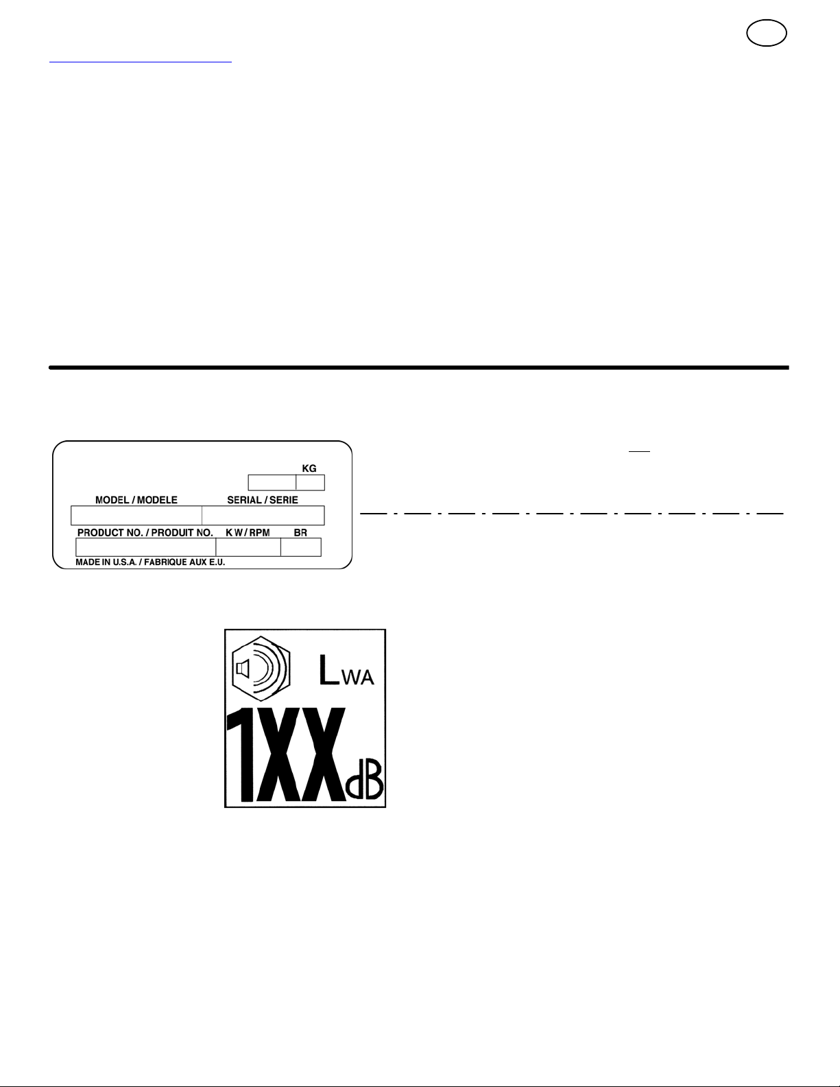
How To Order Replacement Parts
The replacement parts are shown either on the
back pages of this Instruction Book or in a
separate Parts List Book.
Use only manufacturer’s authorized or approved
replacement parts. The letter placed on the end
of the part number denotes the type of finish for
the part, C for chrome, Z for zinc, a PA for
purchased assembly. It is important that you
include this when ordering a part. Do not use
attachments or accessories not specifically
recommended for this unit. In order to obtain
proper replacement parts you must supply the
model number (see nameplate).
To obtain replacement parts, contact:
BRIGGS AND STRATTON CANADA
Factory Customer Service
1195 Coutneypark Drive East
Mississauga, Ont. L5T--1R1
1--800--661--6662
Collect telephone calls will not be accepted.
Replacement parts for the engine, transaxle, or
transmission, are available from the
manufacturer’s authorized service centre found
in the yellow pages of the telephone directory.
Also, s ee the individual engine or transmission
warranties to order replacement parts.
When ordering the following information is
required:
(1) The Model Number
(2) Serial Number
(3) Part Number
(4) Quantity
12
Page 13

TROUBLE SHOOTING CHART
TROUBLE CAUSE CORRECTION
Difficult starting Defective s park plug. Replace s park plug.
GB
Water or dirt in fuel system. Use carburetor bowl drain to flush and refill with
Engine runs erratic Blocked fuel line, empty gas tank, or stale
Engine stalls Unit running on CHOKE. Set c hoke lever to RUN position.
Engine runs erratic;
Loss of power
Excessive vibration Loose parts: damaged impeller Stop engine immediately and disconnect spark
Unit fails to propel itself Drive belt loose or damaged. Replace drive belt.
Unit fails to discharge snow Auger drive belt loose or damaged. Adjust auger drive belt; replace if damaged.
gasoline
Water or dirt in fuel system. Use carburetor bowl drain to flush and refill with
Incorrect adjustment of traction drive cable Adjust traction drive cable.
Worn or damaged friction wheel. Replace friction wheel.
Auger control cable not adjusted correctly. Adjust auger control cable.
Shear bolt broken Replace s hear bolt
Discharge chute clogged. Stop engine immediately and disconnect spark
Foreign object lodged in auger Stop engine immediately and disconnect spark
fresh fuel.
Clean fuel line; check fuel supply; add fresh
gasoline
fresh fuel.
plug wire. Tighten all bolts and make all
necessary repairs. If vibration continues, have
the unit serviced by a competent repairman.
plug wire. Clean discharge chute and inside of
auger housing.
plug wire. Remove object from auger.
13
Page 14

GB
BRIGGS & STRATTON POWER PRODUCTS GROUP, LLC EQUIPMENT OWNER WARRANTY POLICY
Effective M arch 1, 2005 replaces all undated Warranties and all Warranties dated before March 1, 2005
LIMITED WARRANTY
Briggs & Stratton Power Products Group, LLC will repair or replace, free of charge, any part(s) of the equipment that is defective in material or
workmanship or both. Transportation charges on parts submitted for repair or replacement under this warranty must be borne by purchaser. This
warranty iseffective for thetime periods and subj ect to the conditionsstated below.For warranty service, find the nearest Authorized Service Dealer
in our dealer locator map at www.briggspowerproducts.com.
THERE IS NO OTHER EXPRESS WARRANTY. IMPLIED WARRANTIES, INCLUDING THOSE OF MERCHANTABILITY AND FITNESS FOR A
PARTICULAR PURPOSE, ARE LIMITED TO ONE YEAR FROM PURCHASE, ORTO THE EXTENTPERMITTED BY LAWANY AND ALL IMPLIED
WARRANTIES ARE EXCLUDED. LIABILITY FOR INCIDENTAL OR CONSEQUENTIAL DAMAGES ARE EXCLUDED TO THE EXTENT
EXCLUSION IS PERMITTED BY LAW.Some states or countries do not allow limitations on how long an implied warranty lasts, and some states or
countries donot allow the exclusion or limitation of incidental or consequential damages, so the above limitation and exclusion may not apply to you.
This warranty gives you specific legal rights and you may also have other rights which vary from state to state or country to country.
OUR EQUIPMENT*
LAWN & GARDEN
PRODUCTS
SNOWTHROWER
WARRANTY PERIOD**
Consumer Use
2 year
Commercial Use
30 days
OUTBOARD
MOTOR
2 years
none
PRESSURE WASHER
Elite
Seriest
2 years
90 days
All other
Models
1 year
90 days
WATER
PUMP
1 year
90 days
PORTABLE
GENERATOR
WELDER
2 years
1 year
HOME STANDBY GENERATOR SYSTEM
Less than
10 KW
2 years
none
10 KW
or greater
3 years or
1500 hours
none
TRANSFER
SWITCH
3 years
none
* The engine and starting batteries are warranted solely by the manufacturers of those products.
** 2 years for all consumer products in the European Union. Parts only on 2nd year for consumer use of Portable Generator and
Home Standby Generator System -- Less than 10 KW, outside of European Union.
The warranty period begins on the date of purchase by the first retail consumer or commercial enduser, and continues for the period of time stated in the
table above. “Consumer use” means personal residential household use by a retail consumer. “Commercial use” means all other uses, including use for
commercial, income producing or rental purposes. Once equipment has experienced commercial use, it shall thereafter be considered as commercial
usefor purposes of thiswarranty.Equipment used forprime powerin placeof utility arenot applicableto this warranty.Electric powered pressure
washers used for commercial purposes are not warranted.
NO WARRANTYREGISTRATION IS NECESSARY TO OBTAIN WARRANTY ON BRIGGS & STRATTONPRODUCTS. SAVEYOUR PROOF OF PURCHASERECEIPT.IF YOUDO NOTPROVIDE PROOFOF THEINITIAL PURCHASEDATEAT THE TIME WARRANTY SERVICEIS REQUESTED,THE
MANUFACTURING DATE OF THE PRODUCT WILL BE USED TO DETERMINE THE WARRANTY PERIOD.
IMPORTANT: Many units are sold unassembled and cartoned. It is the responsibility of the owner to ensure assembly is performed per the exact instuctions as outlined in the Operating & Maintenance Instruction. Otherunits are purchased pre --assembled. It is the responsibilityof the ownerto ensure the
unit is correctly assembled. The owner must carefully check the unit according to the instructions in the Operating & Maintenance Instructions beforeitis
first used.
ABOUT YOUR EQUIPMENT WARRANTY
We welcome warranty repair and apologize to you for being inconvenienced. Any Authoriz ed Service Dealer may perform warranty repairs. Most warranty
repairs are handled routinely,but sometimes requests for warranty service may notbe appropriate. For example, warranty service would notapply if equipment
damageoccurred becauseof misuse, lack of routinemaintenance, shipping,handling, warehousing or improper installation. Similarly,the warranty is voidif the
manufacturing date or the serial number on the equipment has been removed or the equipment has been altered or modified. During the warranty period, the
Authorized Service Dealer, at its option, will repair or replace any part that, upon examination, is found to be defective under normal use and service.This
warranty will not cover the following repairs and equipment:
S Normal Wear: Outdoor Power Equipment, like all mechanical devices, needs periodic parts and service to perform well. This warranty does not cover
repair when normal use has exhausted the life of a part or the equipment.
S Installation and Maintenance: This warranty does not apply to equipment or parts that have been subjected to improper or unauthorized installation or
alteration andmodification, misuse, negligence, accident, overloading, overspeeding, improper maintenance, repair or storage so as, in our judgment, to
adversely affect its performance and reliability. This warranty also does not cover normal maintenance such as adjustments, fuel system cleaning and
obstruction (due to chemical, dirt, carbon, lime, etc.).
S Other Exclusions: This warranty excludes wear items such as quick couplers, oil gauges, belts, o-rings, filters, pump packing, etc., pumps that have
been run without water supplied or damage or malfunctions resulting from accidents, abuse, modifications, alterations, or improper servicing or freezing
or chemical deterioration. Accessory parts such as guns, hoses, wands and nozzles are excluded from the product warranty. This warranty excludes failuresdue to acts of God and other force majeure events beyond the manufacturers control. Also excluded is used, reconditioned, and
demonstration equipment; equipment used for prime power in place of utility power and equipment used in life support applications.
14
Page 15
INFORMACIÓN GENERAL
Este manual de instrucciones está destinado para una persona con
cierta habilidad mecánica. Como en la mayoría de los manuales de
servicio, no se describen todos los pasos. Pasos como aflojar o apretar
los sujetadores son pasos que la persona, con cierta habilidad
mecánica, puede seguir. Lea y siga estas instrucciones antes de usar la
unidad.
Conozca su producto: Si usted entiende el funcionamiento de la
unidad, obtendrá de ésta el mejor rendimiento. A medida que vaya
leyendo este manual, compare las ilustraciones con la unidad. Aprenda
la ubicación y la función de los controles. Para prevenir accidentes, siga
las instrucciones de funcionamiento y las reglas de seguridad. Guarde
este manual para referencias futuras.
IMPORTANTE: Muchas unidades no están ensambladas y se venden
en cajas de cartón. Es la responsabilidad del propietario asegurarse que
las instrucciones de ensamblaje se sigan exactamente. Otras unidades
se compran ya ensambladas. En las unidades ensambladas, es la
responsabilidad del propietario asegurarse que la unidad esté
correctamente ensamblada. Antes de usar la unidad por primera vez, el
propietario, debe revisarla cuidadosamente según las instrucciones de
este manual.
Características de los controles y del equipo
ES
Manivela de ajuste (2) - Cambia la dirección del ducto de descarga.
Deflector de descarga (3) - Cambia la distancia a la que la nieve es
lanzada.
Ducto de descarga (4) - Cambia la dirección a la que la nieve es
lanzada.
Palanca del propulsor de la barrena (5) - Arranca y para la barrena
(junta y arroja la nieve) que también impulsa el quitanieves.
Características del motor
Interruptor para parar (8) - DebemoversealaposicióndeON
(encendido) para arrancar el motor.
Botón cebador (9) - Inyecta combustible directamente en el carburador
para producir arranques rápidos cuando hace frío.
Manija del arranque a reacción (12) - Se usa para arrancar el motor
en forma manual.
Control de cebado (14) - Se usa para arrancar el motor cuando está
frío.
Declarado valores de emisión de vibración en conformidad con la Directiva
98/37/EC.
En conformidad a la emisión de vibración EN 1033;1996: 7,1
Los valores determinados en el mango cuando la máquina estaba funcionando
sobre una superficie de hormigón a 4500 min--1.
Declarado emisión de ruido transportado por el aire de Lw
conformidad a la Directiva 2000/14/EC, Anexo V.
Nivel de presión del sonido en la posición del operador 84
Los valores determinados en el oído en conformidad a las especificaciones de
EN ISO 11201.
Declarado nivel del potencia
del sonido transportado por
el aire de 104 dB(A) es en
conformidad a la Directiva
2000/14/EC.
m/s2.
A 104 dB es en
dB.
15
Page 16
Estemanualcontiene información de seguridadpara
avisarle de los peligros y riesgos asociados a las
lanzadoras de nieve y cómo evitarlos. La lanzadora
de nieve fue diseñada para la finalidad de eliminar nieve, y no debe
usarse para ningún otro fin. Es importante que usted lea y comprenda
estas instrucciones y que cualquiera que opere el equipo lea y
comprenda estas instrucciones.
ADVERTENCIA
El escape del motor de este producto contiene sustancias químicas que el
estado de California sabe que causan cáncer, defectos de nacimiento u
otros daños reproductivos.
Se usa una palabra de señal (PELIGRO, ADVERTENCIA o PRECAUCIÓN)
con el símbolo de alerta para identificar la probabilidad y potencial gravedad de
lesiones. Además, se puede usar un símbolo de peligro para representar el
tipo de peligro.
PELIGRO indica un peligro que, si no se lo evita, resultará en
muerte o lesión grave.
ADVERTENCIA indica un peligro que, si no se lo evita, podría
resultar en muerte o lesión grave.
PRECAUCIÓN indica un peligro que, si no se lo evita, podría
resultar en lesión menor o moderada.
PRECAUCIÓN, cuando utilizado sin el símbolo de alerta, indica
una situación que podría resultar en daños al equipo.
Símbolos de peligro y significados
Estos símbolos se utilizan en su equipo. Su definición se encuentra en su
manual de operación. Revise y comprenda los significados. El uso de uno de
estos símbolos combinado con una palabra de señal le alertará sobre peligros
potenciales y cómo evitarlos.
Símbolos de operación y significados
Estos símbolos se utilizan en su equipo. Su definición se encuentra en su
manual de operación. Es importante que usted revise y comprenda los
significados. Si no comprende los símbolos, usted puede resultar herido.
Aceite
Combustible
Prender
Apagar
Bulbo de
cebador
Acelerador
Estrangulador
apagado
Estrangulador
prendido
Parar
Lento
Rápido
Adelante
Neutro
Marcha
atrás
Ignición
prendida
Ignición
apagada
Llave de
ignición
Oprimir para
activar arranque
eléctrico
Arranque
eléctrico
ES
Alerta de seguridad - identifica información de seguridad
sobre peligros que pueden resultar en lesión personal.
Manual del operador - léalo y compréndalo antes de
realizar cualquier actividad u operar el equipo.
Barrena rotatoria
Impulsor rotatorio
Vapores
tóxicos
Engranajes
rotatorios
Objetos
arrojados
Mantenga una
distancia segura
del equipo.
Apague el motor y retire el conector de la bujía de
encendido antes de realizar trabajos de
mantenimiento o reparación.
Fuego
Explosión
Descarga
eléctrica
Superficie
caliente
Nunca toque las
piezas giratorias.
Se recomienda el uso
de protección auditiva
para uso prolongado.
Engranar
Engranar
Tracción
Colector de
barrena
Embrague de
barrena
Embrague de
transmisión
Manga de descarga
IZQUIERDA ARRIBA
DERECHA
Arranque del
motor
Marcha del
motor
Motor
apagado
Engranar
Desengranar
Agarres
calentados
Deflector de manga
ABAJO
16
Page 17

ADVERTENCIA: Es máquina es capaz de amputar manos y pies y arrojar objetos. Lea estas normas de
seguridad y respételas estrictamente. El no respetar estas normas podría resultar en pérdida de control de
la unidad, lesiones personales graves o muerte para usted o transeúntes, o daños a la propiedad o equipo.
El triángulo en el texto significa precauciones o advertencias importantes que deben respetarse.
REGLAS PARA OPERACIÓN SEGURA
Prácticas de operación segura para lanzadoras de nieve
IMPORTANTE: Las normas de seguridad requieren controles de
presencia de operador para minimizar el riesgo de lesiones. Su lanzadora
de nieve está equipada con dichos controles. No intente derrotar la
función de control de presencia del operador bajo ninguna circunstancia.
Capacitación
1. Lea, comprenda y siga todas las instrucciones en la máquina y en los
manuales antes de operar esta unidad. Esté completamente
familiarizado con los controles y el uso correcto del equipo. Sepa
cómo parar la unidad y desactive los controles rápidamente.
2. Nunca permita que niños operen el equipo. Nunca permita que
adultos operen el equipo sin instrucción apropiada.
3. Mantenga el área de operación libre de personas, especialmente
niños pequeños y mascotas.
4. Tenga cuidado de no resbalarse o caerse, especialmente al dar
marcha atrás.
Preparación
1. Inspeccione a fondo el área donde se utilizará el equipo y retire todo
felpudo, trineo, tabla, cable y otros objetos extraños.
2. Desengrane todos los embragues y coloque la transmisión en neutro
antes de poner en marcha el motor.
3. No opere el equipo sin vestir un abrigo de invierno adecuado. Use
calzado que mejore el equilibrio sobre superficies resbaladizas. Evite
ropa floja que pueda quedar atascada en piezas en movimiento.
4. Manipule el combustible con cuidado; el mismo es altamente
inflamable.
a. Use un recipiente de combustible aprobado.
b. Nunca agregue combustible a un motor en funcionamiento o un
motor caliente.
c. Llene el tanque de combustible en exteriores y con extremo
cuidado. Nunca llene el tanque de combustible en interiores. Vuelva
a colocar la tapa del tanque de combustible, ciérrela bien y limpie el
combustible derramado.
d. Nunca llene recipientes dentro de un vehículo o sobre el lecho de
un camión o remolque con un forro plástico. Siempre coloque los
recipientes sobre el suelo, lejos del vehículo, antes de llenarlos.
e. Cuando resulte conveniente, retire los equipos a gas del camión o
remolque y colóquelos sobre el suelo para llenarlos con
combustible. Si esto no es posible, entonces abastézcalos sobre un
remolque con un recipiente portátil, en lugar de una boquilla de
surtidor de gasolina.
f. Mantenga la boquilla en contacto con el borde de la boca del
tanque de combustible o recipiente en todo momento, hasta haber
terminado de colocar combustible. No use un dispositivo para trabar
y abrir boquillas.
g. Vuelva a colocar la tapa del tanque de combustible, ciérrela bien y
limpie el combustible derramado.
h. Si se derrama combustible sobre la ropa, cámbiese la ropa de
inmediato.
5. Use cables alargadores y receptáculos especificados por el fabricante
para todas las unidades con motores con transmisión eléctrica o
arranque eléctrico.
ES
6. Ajuste la altura de la caja del colector para limpiar superficies con
grava o piedra triturada.
7. Nunca intente realizar ajustes con el motor en marcha (excepto
cuando lo recomiende el fabricante específicamente).
8. Permita que el motor y la lanzadora de nieve se ajusten a las
temperaturas exteriores antes de eliminar nieve.
9. Siempre use gafas de seguridad o protección para los ojos durante el
funcionamiento o al realizar un ajuste o reparación para proteger los
ojos contra objetos extraños que la máquina pueda arrojar.
Operación
1. No coloque las manos o pies cerca o debajo de piezas giratorias.
Manténgase alejado de la abertura de descarga en todo momento.
2. Tenga extremo cuidado al operar la máquina sobre caminos, entradas
o c alles de grava, o al cruzarlos. Manténgase atento a peligros
ocultos o tráfico.
3. Al golpear un objeto extraño, pare el motor, retire el cable de la bujía,
desconecte el cable en motores eléctricos, inspeccione bien la
lanzadora de nieve para constatar si sufrió daños, y repare los daños
antes de volver a poner en marcha y operar la lanzadora de nieve.
4. Si la unidad comienza a vibrar anormalmente, pare el motor y busque
la causa de inmediato. La vibración es, en general, advertencia de
problemas.
5. Pare el motor siempre que deje la posición de operación, antes de
destapar la caja del colector/impulsor o manga de descarga, y al
realizar reparaciones, ajustes o inspecciones.
6. Al limpiar, reparar o inspeccionar, asegure que se hayan detenido el
colector/impulsor y todas las piezas móviles. Desconecte el cable de
la bujía y aleje el cable de la bujía para evitar un arranque accidental.
7. No haga funcionar el motor en interiores, excepto al arrancar el motor
y para transportar la lanzadora de nieve hacia dentro o hacia fuera
del edificio. Abra las puertas al exterior; los vapores de escape son
peligrosos (contienen MONÓXIDO DE CARBONO, un GAS
INODORO y MORTAL).
8. Tenga extremo cuidado al operar en laderas. No intente limpiar
laderas empinadas.
9. Nunca opere la lanzadora de nieve sin protecciones, placas u otros
dispositivos protectores apropiados en su lugar y funcionando
correctamente.
10. Nunca apunte la descarga hacia personas o áreas en las que pueda
ocurrir daño a la propiedad. Mantenga a los niños y a otras personas
alejados.
11. No sobrecargue la capacidad de la máquina al intentar eliminar la
nieve a un ritmo demasiado rápido.
12. Nunca opere la máquina a velocidades altas de transporte sobre
superficies resbaladizas. Mire hacia atrás y tenga cuidado al
desplazar el equipo marcha atrás.
13. Desconecte la electricidad al colector/impulsor cuando la lanzadora
de nieve sea transportada o no se esté utilizando.
14. Use solo acoplamientos y accesorios aprobados por el fabricante de
la lanzadora de nieve (tales como cabinas, cadenas para neumáticos,
etc.).
15. Nunca opere la lanzadora de nieve sin buena visibilidad o luz.
Siempre asegúrese de estar bien equilibrado y agárrese de las
manijas firmemente. Camine; nunca corra.
17
Page 18

16. Nunca toque un motor o silenciador caliente.
17. Nunca opere la lanzadora de nieve cerca de encerramientos de
vidrio, automóviles, cuadros de ventana, puntos de descenso y
lugares similares, sin ajustar el ángulo de descarga de nieve.
18. Nunca apunte la descarga hacia transeúntes ni permita personas
delante de la unidad.
19. Nunca deje una unidad en funcionamiento sin supervisión. Siempre
desengrane los controles de barrena y tracción, pare el motor y retire
las llaves.
20. No opere la unidad mientras esté bajo el efecto de alcohol o drogas.
21. Tenga presente que el operador es responsable por accidentes que
ocurran a otras personas o propiedad.
22. Datos indican que operadores de 60 años y más están involucrados
en un gran porcentaje de lesiones asociadas a equipos eléctricos.
Estos operadores deben evaluar su capacidad de operar la unidad de
manera l o suficientemente segura para protegerse a sí mismos y a
los demás contra lesiones.
23. NO use bufandas largas o ropa floja que pueda enredarse en piezas
móviles.
24. La nieve puede esconder obstáculos. Asegúrese de remover todos
los obstáculos del área a ser limpiada.
Niños
Pueden ocurrir accidentes trágicos si el operador no está atento a la
presencia de niños. Los niños suelen sentirse atraídos a la unidad y a la
actividad de operación. Nunca presuponga que los niños permanecerán
donde los vio por última vez.
1. Mantenga a los niños fuera del área y bajo la vigilancia atenta de otro
adulto responsable.
2. Esté atento y apague el equipo si niños ingresan al área.
3. Nunca permita que niños operen la unidad.
4. Tenga cuidado adicional al acercarse a esquinas ciegas, arbustos,
árboles u otros objetos que puedan impedir la visión.
Cómo limpiar una manga de descarga tapada
El contacto de las manos con el impulsor rotatorio dentro de la manga de
descarga es la causa más común de lesión asociada a lanzadoras de
nieve. Nunca use su mano para destapar la manga de descarga.
Para destapar la manga:
1. APAGUE EL MOTOR.
2. Espere 10 segundos para asegurar que las aletas del impulsor hayan
dejado de girar.
3. Siempre use una herramienta para destapar y no sus manos.
Reparación, mantenimiento y almacenaje
1. Verifique, en intervalos frecuentes, que los pernos de seguridad y
otros pernos estén bien apretados para asegurar que el equipo esté
en condiciones seguras de funcionamiento.
2. Nunca almacene la máquina con combustible dentro del tanque,
dentro de un edificio con fuentes de ignición presentes, tales como
calderas de agua y calefactores o secadores de ropa. Permita que el
motor se enfríe antes de almacenar en cualquier lugar cerrado.
ES
3. Siempre consulte el manual del operador para obtener detalles
importantes, s i s e almacenará la lanzadora de nieve por un periodo
prolongado.
4. Mantenga o reemplace las etiquetas de seguridad e instrucciones,
según sea necesario.
5. Opere la máquina algunos minutos después de lanzar nieve para
evitar el congelamiento del colector/impulsor.
6. Si se derrama combustible, no intente colocar el motor en marcha;
aleje l a máquina del área del derrame y evite crear una fuente de
ignición hasta que se hayan disipado los vapores del combustible.
7. Siempre utilice prácticas seguras de abastecimiento y manipulación
de combustible al cargar combustible en la unidad después de
transporte o almacenaje.
8. Siempre siga las instrucciones de manual del motor para
preparaciones para almacenaje, antes de almacenar la unidad, tanto
para periodos cortos como largos.
9. Siempre siga las instrucciones del manual de motor para
procedimientos adecuados de arranque al colocar la unidad
nuevamente en servicio.
10. Mantenga o reemplace las etiquetas de seguridad e instrucciones,
según sea necesario.
11. Mantenga las tuercas y tornillos apretados y mantenga el equipo en
buenas condiciones.
12. Nunca altere los dispositivos de seguridad. Verifique periódicamente
que funcionen bien, y realice todas las reparaciones necesarias si no
funcionan correctamente.
13. Los componentes están sujetos a desgaste, daños y deterioro.
Verifique los componentes con frecuencia y reemplácelos por piezas
recomendadas por el fabricante, cuando sea necesario.
14. Verifique el funcionamiento de los controles con frecuencia. Ajuste y
repare, según sea necesario.
15. Solo use piezas de reposición autorizadas por la fábrica al hacer
reparaciones.
16. Siempre cumpla con las especificaciones de la fábrica para todos las
configuraciones y ajustes.
17. Solo se debe utilizar lugares de servicio autorizados para
requerimientos mayores de servicio y reparación.
18. Nunca intente realizar reparaciones significativas en esta unidad, a
no ser que haya recibido la capacitación necesaria. Procedimientos
de servicio incorrectos pueden resultar en funcionamiento peligroso,
daños al equipo y anulación de la garantía del fabricante.
19. Verifique, en intervalos frecuentes, que los pernos de seguridad y
otros pernos estén bien apretados para asegurar que el equipo esté
en condiciones seguras de funcionamiento.
Emisiones
1. El escape del motor de este producto contiene sustancias químicas
que, en ciertas cantidades, se sabe que causan cáncer, defectos de
nacimientos o daños reproductivos.
2. Si estuviera disponible, busque información relevante de Periodo de
Durabilidad de Emisiones e Índice de Aire en la etiqueta de emisiones
del motor.
Sistema de ignición
1. Este sistema de encendido por chispa cumple con la ICES-002
canadiense.
18
Page 19

ENSAMBLAJE
Lea y siga las instrucciones de ensamble y ajuste para el quitanieves. Todos los sujetadores
están en la bolsa de piezas. No bote ninguna
pieza o material hasta que la unidad esté ensamblada.
ADVERTENCIA: Antes de hacerle
mantenimiento o montarle alguna
pieza a l quitanieves, desconecte el
cable de la bujía.
NOTA: En este manual de instrucciones, la
izquierda y la derecha se refieren a la ubicación de las piezas con respecto al operador
cuando éste se encuentra detrás de la unidad.
NOTA: El par de torsión se mide en libras-pie (N.m en métrico). Esta medida indica lo
apretado que debe estar un perno o una tuerca. El par de torsión se mide con una llave
dinamométrica.
NOTA: Los sujetadores y otras piezas
sueltas se muestran en tamaño real en la
Figura 2 en la página 69.
NOTA: Las ilustraciones comienzan en la
página2yenlaspáginas70hastala75.
Herramientas necesarias
1 Cuchillo
1 Alicates
2 Llaves de 1/2 de plg.
2 Llavesde9/16deplg.
2 Llaves de 3/4 de plg.
1 Cinta de medir o regla
1 Destornillador
Cómo sacar el quitanieves de la caja
1. (Figura 3) El quitanieves se muestra en posición de transporte.
2. Corte y bote los amarres plásticos que sujetan la manivela de ajuste de dirección de
descarga.
3. Corte los cuatro lados de la caja y deje los
paneles laterales sobre el s uelo.
4. Ubique todas las piezas que están empaquetadas separadamente y sáquelas de la caja.
5. Quite y bote el material de embalaje que rodea al quitanieves.
6. (Figura 1) Para facilitar el transporte, los pa-
tinesdealturaajustable(7)se fijaron a la
paleta. Quite los tornillos (17) que sujetan
los patines de altura ajustable (7) alapaleta.
7. Agarre el quitanieves por el mango inferior y
sáquelo de la paleta.
PRECAUCIÓN: NO retroceda sobre los
cables.
8. Quite el material de embalaje del ensamble
del mango.
9. Corte los amarres que sujetan los cables de
control del embrague (1) al mango inferior
(2). Aleje los cables del armazón del motor.
Cómo montar el puño y la manivela de
ajuste de de la dirección de descarga
de nieve
1. (Figura 4) Afloje pero no quite los sujetadores (1) en los agujeros superiores del mango
inferior.
2. Quite los sujetadores y el perno de anilla de
la manivela de ajuste de descarga (11) ubicados en los agujeros inferiores del mango
inferior.
3. (Figura 1) Ponga la palanca de cambios (6)
en primera de avance.
4. (Figura 4) Suba el mango superior (2) hasta la posición de funcionamiento.
NOTA: Asegúrese de que los cables no
estén atrapados entre los mangossuperior e inferior.
5. Instale los sujetadores y el perno de anilla
de la manivela de ajuste de descarga (11)
que quitó en el paso 2 NO apriete los sujetadores hasta que todos estén en posición.
6. (Figura 6) Use el pasador de chaveta (12)
para conectar l a maniveladeajustede
descarga (15) alaarticulación universal
(16).
7. (Figura 4) Apriete la tuerca del perno de
anilla (11). Asegúrese de que el perno de
anilla (11) está adecuadamente alineado y
que la manivela (18) pueda girar libremente.
8. Apriete todos los sujetadores de los mangos.
Cómo instalar los puños
NOTA: Si los puños ya están instalados, pase a la próxima selección.
Puño de la palanca del tubo de
descarga de nieve (Figura 10)
1. Instale el puño de la palanca del tubo de
descarga de nieve (1) en la palanca (3)
hasta que quede apretado contra la tuerca
(2). En algunos modelos el puño de la palanca del tubo de descarga de nieve (1)
viene ya instalado.
2. Asegúrese que el reborde (4) del puño de
la palanca del tubo de descarga de nieve
(1) quede orientado hacia el motor.
3. Apriete la tuerca (2) contra la parte inferior
del puño de la palanca del tubo de des-
carga de nieve (1).
Puño del selector de velocidad
(Figura 10) Instale el puño del selector de ve-
locidad (11) en la palanca de cambio de velocidad (1). En algunos modelos el puño del
selector de velocidad (11) ya viene instalado.
Cómo instalar la varilla de control de
velocidad
1. (Figura 9) Instale la rótula (6), ubicada en el
extremo i nferior de la varilla de control de
velocidad (2), en la unidad de la horquilla
de cambios (7). Los sujetadores (8) en la
rótula (6) vienen preinstalados de fábrica.
Ellargodelarótula (6) ydelavarilla de
control de velocidad (2) ha sido preajusta-
do en la fábrica. Si es necesario hacer un
ajuste, afloje la tuerca (9). Retire los sujeta-
dores (8) para desconectar la rótula (6) de
19
E
la unidad de la horquilla de cambios (7).
Para alargar o acortar la varilla de control
de velocidad (2), gire el adaptador (10)
hasta conseguir el largo adecuado.
2. (Figura 10) Monte el puño (11) en la palan-
ca de cambio de velocidad (5). En algunos
modelos el puño (11) viene ya instalado. Para fijarlo en su posición, apriete la contra-
tuerca hexagonal (10) contra la parte
inferior del puño (11).
3. Asegúrese de que la palanca de cambio de
velocidad (5) funcione bien. Mueva la palanca de cambio de velocidad (5) pasando
por todas las velocidades.
Cómo ensamblar el conducto deflector
1. (Figura 7) Retire el perno de coche (1).
2. Levante el conducto deflector (2) hasta la
posición de operación (3).
3. Sujete el conducto deflector (2) alabrida
(4) usando los pernos de coche (1). Asegú-
rese de instalar los pernos de coche (1) de
manera que las cabezas de estos queden en
la parte interior de la brida (2).
4. Fíjelo con las arandelas (5) ylascontra-
tuercas (6).
5. Apriete firmemente las contratuercas (6).
NOTA: Compruebe que todos los pernos de
coche en la brida estén apretados. PERO NO
LOS APRIETE DEMASIADO.
Revisión de los cables
1. (Figura 8) Revise el cable propulsor de
tracción (1) yelcable propulsor de la ba-
rrena (2). Si los extremos inferiores de los
cables se han desconectado, vuelva a instalarlos.
2. (Figura 11) Si la parte de arriba de los ca-
bles (5) se ha desconectado de las palancas propulsoras (6), una los cables (5) al
accesorio “ Z”(7).
Cómo establecer la altura de los
patines (Figura 1)
El quitanieves tiene patines de altura ajustable
(7) montados en la parte exterior del alojamiento de la barrena (4). Para ajustar la altura
de los patines vea “Cómo ajustar la altura de
los patines” en la sección de Mantenimiento.
Cómo establecer la longitud de los
cables
Los cables fueron ajustados en la fábrica y no
debe ser necesario ajustarlos nuevamente. Sin
embargo, después de colocar los mangos en su
posición de operación, los cables podrían quedar muy tirantes o muy flojos. Si es necesario
ajustarlos, consulte “Cómo revisar y ajustar los
cables, en la sección de Servicio y Ajustes.
Cómo ensamblar el cortanieves
(si es parte de la unidad)
Los cortanieves se usan para abrir una pasada
a través de la nieve cuando ésta es más profunda que el alojamiento de la barrena.
1. (Figura 12) Afloje los sujetadores (2) que
afirman l os cortanieves (1) al alojamiento de
la barrena.
Page 20

2. Levante los cortanieves (1) alaalturadeseada.
3. Apriete los sujetadores (2).
Cómo preparar el motor
NOTA: El motor fue enviado de la fábrica con
aceite. Revise el nivel de aceite. Añada aceite
según sea necesario.
ADVERTENCIA: Siga las instrucciones del fabricante del motor en
cuanto al tipo de combustible y
aceite que se debe usar. Use siempre un
contenedor de combustible seguro. No fume al poner gasolina en el motor. Cuando
esté en un recinto cerrado, no ponga gasolina en el tanque. Antes de poner gasolina,
apague el motor y déjelo enfriar por varios
minutos.
Revise el aceite. Siga las instrucciones del fabricante del motor en cuanto al tipo de combustible
y aceite que se debe usar. A ntes de usar la unidad, lea la información sobre seguridad, operación, mantenimiento y almacenamiento.
¡Atención! Antes de utilizar la unidad:
U Revise los sujetadores. Compruebe que
todos estén bien apretados.
U En los modelos de arranque eléctrico, la
unidad ha sido enviada con el cable del
sistema de arranque enchufado al mo tor. Antes de utilizar la unidad, desenchufe el cable de arranque del motor.
OPERACIÓN
NOTA: Las ilustraciones comienzan en la
página2yenlaspáginas70hastala75.
PRECAUCIÓN: Sólo use acoplamientos y
accesorios aprobados por el fabricante del
quitanieves (como cadenas para las llantas,
los juegos del arranque eléctrico, etc.).
Conozca su quitanieves (Figura 1)
Lea este manual de instrucciones y las reglas
de seguridad antes de operar el quitanieves.
Compare la ilustración con el quitanieves para
familiarizarse con la ubicación de los diversos
controles y ajustes.
Cómo controlar la descarga de nieve
ADVERTENCIA: Nunca dirija la
descarga de nieve hacia los trans-
eúntes.
ADVERTENCIA: Pare siempre el
motor antes de destapar el tubo de
descarga o el alojamiento de la barrena, y antes de dejar solo el quitanieves.
1. (Figura 1) Gire la palancadeajustede
descarga (2) para cambiar la dirección de la
descarga de nieve.
2. Empuje la palanca de ajuste de descarga
(20) hacia delante para lanzar la nieve a una
buena altura y distancia. Jale la palanca de
ajuste de descarga (20) hacia atrás para
lanzar la nieve hacia abajo.
Cómo parar la descarga de nieve
(Figura 1)
1. Para detener la descarga de nieve, suelte la
palanca del propulsor de la barrena (5).
2. Para parar las ruedas, suelte la palanca del
propulsor de tracción (1).
3. Para parar el motor, mueva el interruptor de
parada (13) alaposiciónAPAGADO(OFF).
PRECAUCIÓN: Para parar el motor, no mueva el control del estrangulador a la posición
de ESTRANGULACIÓN. Esto puede producir
petardeo o daño al motor.
Cómo avanzar o retroceder (Figura 1)
1. Para cambiar la velocidad de marcha, suelte
primero la palanca del propulsor de trac-
ción (1) y luego mueva la palanca de cambio de velocidades (6) a la velocidad
deseada.
2. La velocidad de marcha queda determinada
por las condiciones de la nieve. Seleccione
la velocidad moviendo la palanca de cam-
bio de velocidades (6) hasta la muesca correspondiente de la placa de la palanca de
cambios.
Velocidad,1, 2 Mojada, pesada
Velocidad 3 Ligera
Velocidad 4 Muy ligera
Velocidad,5, 6 Sólo para transporte
3. Para avanzar, oprima la palanca del propul-
sor de tracción (1). Sujete firmemente el
mango cuando el quitanieves comience a
avanzar. Guíe el quitanieves moviendo el
manubrio hacia la izquierda o la derecha.
No intente empujar el quitanieves.
4. Para retroceder, suelte la palanca del pro-
pulsor de tracción (1).
5. Mueva la palanca de cambio de velocida-
des (6) a la primera o segunda velocidad de
marcha atrás.
6. Oprima la palanca del propulsor de trac-
ción (1).
IMPORTANTE: No mueva la palanca de cambio de velocidades (6) mientras la palanca
del propulsor de tracción (1) esté oprimida.
Cómo lanzar la nieve (Figura 1)
1. Oprima la palanca del propulsor de la barrena (5).
2. Para dejar de lanzar nieve, suelte la palanca
del propulsor de la barrena (5).
ADVERTENCIA: La operación del
quitanieves puede hacer que obje-
tos sean lanzados a los ojos de las
personas, lo cual puede producir heridas
graves. Use siempre anteojos o gafas de
seguridad para proteger sus ojos durante
la operación del quitanieves. Se recomien da el uso de gafas de seguridad estándar o
una careta de seguridad de vista amplia
sobre los anteojos.
Cómo usar el pasador de bloqueo de l a
rueda (Figura 13)
1. La rueda izquierda va sujeta al eje con un
pasador klick (1). Esta unidad fue enviada
con el pasador klick (1) en el agujero de la
rueda en posición de bloqueo (2).
2. Para maniobrar con facilidad en condiciones
de nieve ligera, cambie el pasador klick (1)
alaposición de desbloqueo (3).
20
E
3. Quite el pasador klick (1) de la posición de
bloqueo de la rueda (2). Empuje el pasa dor klick (1) sólo a través del agujero del eje
desbloqueado. La unidad quedará en la posición de tracción en una sola rueda desblo-
queada (3).
Pasos previos al arranque del motor
1. Antes de arrancar el motor o hacerle servicio
o mantenimiento, familiarícese con el quitanieves. Asegúrese de entender el funcionamiento y la ubicación de todos los controles.
2. Revise la tensión del cable del embrague
antes de arrancar el motor. Ver “Cómo ajustar el cable del embrague” en la sección de
Mantenimiento de este manual.
3. Asegúrese de que todos los sujetadores están apretados.
4. Asegúrese de que los patines de altura ajustable estén debidamente ajustados. Ver “Cómo ajustar la altura de los patines” en la
sección de Mantenimiento de este manual.
5. Revise la presión de las llantas. La presión
correcta es de 14 PSI (1 BAR) a 17 PSI
(1,25 BAR). No exceda la presión de aire
máxima que aparece indicada en el lado de
la llanta.
Cómo parar el motor (Figura 1)
6. Mueva el interruptor de parada (13) ala
posición APAGADO (OFF).
7. Saque la llave de seguridad (8).
PRECAUCIÓN: Para parar el motor, no mueva el control del estrangulador a la posición
de ESTRANGULACIÓN. Esto puede producir
petardeo o daño al motor.
Cómo arrancar el motor (Figura 1)
Modelos e quipados con arranque eléctrico
NOTA: Es posible instalar un juego de arran -
que eléctrico en motores de arranque manual. Hay juegos de arranque eléctrico
disponibles en el centro de servicio autorizado más cercano.
ADVERTENCIA: El arranque está
equipado con un cordón y enchufe
de tres clavijas diseñado para funcionar con corriente doméstica de 220 voltios de C.A. El cordón de alimentación debe
estar conectado a tierra en todo momento
para evitar la posibilidad de descarga eléctrica que puede lesionar al operador. Siga
cuidadosamente todas las instrucciones de
la sección “Arranque del motor”. Asegúrese de que el cableado de su casa es un sistema de tres cables conectado a tierra. Si
no está seguro, pregúntele a un electricista
licenciado. Si su casa no tiene un sistema
de tres cables conectado a tierra, no use
este arranque eléctrico bajo ninguna circunstancia. Si su sistema está conectado a
tierra pero no dispone de un enchufe de
tres agujeros conectado a tierra, haga que
un electricista licenciado instale el enchufe
en cuestión. Para conectar el cordón de
alimentación de 220 voltios de C.A., conecte
siempre el cordón al enchufe (11) del motor
primero. Luego, conecte el otro extremo en
el enchufe de tres agujeros conectado a tierra. Cuando desconecte el cordón de alimentación, desenchufe siempre el extremo
del enchufe de tres agujeros primero.
Page 21

Cómo arrancar el motor en frío (Figura 1)
1. Revise el aceite del motor.
2. Llene el tanque de combustible con gasolina
regular sin plomo. Ver “Cómo preparar el
motor”.
3. Asegúrese de que la palanca del propulsor
de tracción (1) ylapalanca del propulsor
de la barrena (5) estén desenganchadas.
4. Mueva el interruptor de parada (13) ala
posición E NCENDIDO (ON).
5. Inserte la llave de seguridad (8).
6. Mueva la perilla de estrangulación (14) a
la posición de estrangulación.
7. (Arranque eléctrico) Conecte el cordón de
alimentación en el enchufe (11) ubicado en
el motor.
8. (Arranque eléctrico) Enchufeelotroextremo del cordón de alimentación en el enchufe
de 220 voltios de C.A. de tres agujeros conectado a tierra. (Ver la ADVERTENCIA en
esta sección).
9. Oprima el botón de cebado (9). Cada vez
que oprima el botón de cebado (9), espere
dos segundos. Para saber el número de veces que hay que oprimir el botón de cebado
(9), vea las instrucciones del fabricante del
motor.
10.(Arranque eléctrico) Oprima el botón de
arranque eléctrico (10) hasta que el motor
arranque. No haga girar el motor por más de
5 s egundos cada vez. Espere un minuto entre arranques para permitir que el motor se
enfríe.
11. (Arranque manual) Jale lentamente la ma-
nija de arranque manual (12) hasta que
sienta resistencia, entonces jale la manija de
un tirón para arrancar el motor. No deje que
la manija de arranque manual (12) se devuelva con fuerza inmediatamente después
de jalarla. Haga que la manija (12) se devuelva lentamente.
12.Sielmotornoarrancaalos5ó6intentos,
vea las instrucciones en la “Tabla de localización y reparación de averías”.
13.Deje que el motor se caliente por varios minutos. Mientras se calienta el motor, mueva
la perilla de estrangulación (14) hacia la
posición MARCHA (RUN). Espere hasta que
el motor esté corriendo suavemente antes de
cada ajuste de estrangulación.
14.(Arranque eléctrico) Desconecte primero el
cordón de alimentación del enchufe de tres
agujeros. Luego, desconecte el cordón de
alimentación del motor de arranque.
NOTA: Cuando la temperatura esté por
debajo de los 0°F(--18°C), deje que el mo-
tor se caliente durante varios minutos antes de comenzar a lanzar nieve.
ADVERTENCIA: Nunca deje correr
el motor dentro de un recinto cerra-
do o en áreas con poca ventilación.
Los gases de escape del motor contienen
monóxido de carbono, que es un gas inodoro y mortal. Mantenga las manos, los
pies, el pelo y las ropas sueltas alejadas de
las partes en movimiento ubicadas en el
motor o la barrena del quitanieves. La temperatura del silenciador y de las piezas alrededor del silenciador pueden exceder los
150°F. Evite el contacto con estos componentes.
Cómo arrancar el motor en caliente (Figura 1)
Si el motor ha estado andando y todavía está
caliente, deje el control de estrangulación (14)
en la posición de apagado y no pulse el botón
de cebado (9). Si el motor no arranca, siga las
instrucciones de la sección “Cómo arrancar el
motor en frío”.
NOTA: No use el botón cebador (9) para
arrancar un motor caliente.
Cómo arrancar un motor con el arranque eléctrico congelado (Figura 1)
Si el arranque eléctrico está congelado y no hace girar el motor, siga las siguientes instrucciones.
1. Jale la manija de arranque manual (12) lo
más afuera posible.
2. Suelte la manija de arranque manual (12) y
deje que la manija de arranque manual
(12) se enrolle rápidamente. Repita hasta
que el motor arranque.
Los motores calientes producen condensación
cuando la temperatura está baja. Para evitar el
posible congelamiento del arranque manual y de
los controles del motor, proceda como se indica
a c ontinuación después de cada trabajo de remoción de nieve.
1. Antes de guardar el quitanieves, haga que
funcione unos pocos minutos para prevenir
que se congele la barrena rotatoria / impulsor.
2. Con el motor apagado, deje que el motor se
enfríe por varios minutos.
3. Jale lentamente la cuerda de arranque manual hasta que sienta resistencia, y pare.
Deje que la cuerda de arranque se enrolle.
Repita este paso tres veces.
4. Con el motor apagado, limpie toda la nieve y
la humedad de la tapa del carburador en el
área de los controles y palancas. También
mueva v arias v eces el control de estrangulación y la manija de arranque.
E
Cómo quitar la nieve u otros desechos
del alojamiento de la barrena
ADVERTENCIA: No intente quitar
con sus manos la nieve o des-
echos que se hayan acumulado en
el alojamiento de la barrena. Use el bastón
de limpieza o una palanca para quitar la
nieve y los desechos.
(Figura 5) Algunos modelos traen sobre el alojamiento de la barrena un bastón de limpieza
(1). Use el bastón de limpieza para quitar la nieve del alojamiento de la barrena.
1. (Figura 1) Suelte la palanca del propulsor
de la barrena (5).
2. Mueva el control de aceleración (13), si lo
tiene, a la posición de parada.
3. Retire la llave de seguridad (8).
4. Desconecte el cable de la bujía.
5. No ponga las manos en el alojamiento de la
barrena (4) ni el tubo de descarga (3).
6. (Figura 5) Use el bastón de limpieza (1) o
una palanca para quitar la nieve o desechos.
Sugerencias para el lanzamiento de
nieve
1. Para obtener el máximo rendimientodel quitanieves, ajuste la velocidad de marcha. En
nieve profunda, congelada o mojada, avance
más lento. Si las ruedas patinan, reduzca la
velocidad de avance.
2. El lanzamiento de nieve más eficiente se logra c uando la nieve se quita inmediatamente
después de la nevada.
PRECAUCIÓN: No sobrecargue la capacidad de la máquina al intentar limpiar la
nieve en forma rápida.
3. Para quitar completamente la nieve, sobreponga levemente las pasadas del quitanieves.
4. Cuando sea posible, descargue la nieve a
favor del viento.
5. Para uso normal, fije los patines de manera
que la barra raspadora quede a un 1/8 de
pulgada por encima de los patines. Para superficies de nieve extremadamente apisonada, ajuste los patines hacia arriba de manera
que la barra raspadora toque el suelo.
6. La máquina no debe recoger y lanzar piedras o grava. En superficies de grava o ripio,
fije los patines a 1--1/4 de pulgada por debajo de la barra raspadora. Ver “Cómo ajustar
la altura de los patines” en la sección de
mantenimiento.
7. Después de cada trabajo, deje que el motor
funcione en marcha lenta por unos minutos.
Así se derrite la nieve y el hielo acumulados
en el motor.
8. Limpie el quitanieves después de cada uso.
9. Quite el hielo, la nieve y los desechos de todo el quitanieves. Enjuáguelo con agua para
quitarle toda la sal y otros productos químicos. Seque el quitanieves con un trapo.
21
Page 22

RESPONSABILIDADES DEL CLIENTE
E
TABLA DE MANTENIMIENTO
REGISTROS DE SERVICIO
Anote las fechas en que
se haga el mantenimiento
Revisar el nivel de aceite del motor
Cambiar el aceite del motor
Revisar y apretar todos los tornillos y tuercas
Revisar la bujía
Ajustar la correa propulsora
Revisar el combustible
Vaciar el tanque de combustible
Revisar el ajuste del cable del embrague de
la barrena
(Ver “Cómo ajustar los cables”)
Revisar el ajuste del cable del embrague de
tracción
(Ver “Cómo ajustar los cables”)
Lubricar todos los puntos de giro
Lubricar el eje de la barrena
(Ver “Cambio de pernos de ruptura”)
Lubricar las ruedas dentadas y las cadenas
de propulsión
normal.
Antes
de ca-
da uso
Prime-
ras
2
horas
Cada
5
horas
Cada
10
horas
Cada
25
horas
√ √ √
√ √
√ √
√ √
√ √ √
√
√ √
√ √
√
√ √
√ √
Cada
tempo-
rada
Antes
de
guar-
darlo
√
√
FECHA DEL SERVICIO
MANTENIMIENTO
NOTA: Las ilustraciones comienzan en la
página2yenlaspáginas70hastala75.
Consulte la siguiente sección de mantenimiento
para mantener la unidad en buenas condiciones
de funcionamiento. Toda la información respecto
al mantenimiento del motor se encuentra en las
instrucciones del fabricante del motor. Lea este
manual antes de arrancar el motor.
ADVERTENCIA: Antes de hacer
una inspección, reparación o ajuste (excepto en el carburador), des -
conecte el cable de la bujía.
Recomendaciones generales
La garantía de este quitanieves no cubre partes
que hayan sido sometidas a abuso o negligencia por parte del operador. Para recibir el valor
completo de la garantía, el operador debe mantener el quitanieves de acuerdo con las instrucciones de este manual.
Se deben hacer algunos ajustes periódicamente
para mantener el quitanieves en condiciones
óptimas de operación.
Después de cada uso
G Vea si hay piezas sueltas o dañadas.
G Apriete los sujetadores que estén sueltos.
G Revise y hágale mantenimiento a la barrena.
G Revise los controles para asegurarse de que
funcionan correctamente.
G Si alguna parte está gastada o dañada,
cámbiela inmediatamente.
G Revise todas las calcomanías y etiquetas
que haya con instrucciones de seguridad.
Reemplace c ualquiera calcomanía o etiqueta
que esté perdida o que no se pueda leer
claramente.
Todos los ajustes que aparecen en la sección de
Mantenimiento deben hacerse por lo menos
una vez cada estación.
Según sea necesario
Los siguientes ajustes se deben hacer más de
una vez por estación.
1. Ajuste la correa del propulsor de la barrena
después de las primeras 2 ó 4 horas, a mitad
de la estación, y dos veces cada estación de
ahí en adelante. Ver “Cómo ajustar l a correa
del propulsor de la barrena” en la sección de
mantenimiento.
Lubricación
Cada 10 horas
1. Lubrique los accesorios Zerk (1) cada diez
horas con una pistola engrasadora.
2. Cada vez que cambie un perno de seguridad, engrase también el eje de la barrena.
3. Lubrique todos los puntos de giro.
(Figura 14)
22
Cada 25 horas
Engranaje de rotación del canal de descarga
(Figura 6) Lubricar el engranaje de rotación
del canal de descarga (1) conaceitedeauto-
móvil.
Cadenas
1. (Figura 1) Ponga la palanca de cambio de
velocidades (6) en primera.
2. Vacíe el tanque de gasolina. Ponga el quitanieves en posición vertical sobre la parte delantera del alojamiento de la barrena (4).
ADVERTENCIA: Vacíe el tanque de
gasolina a l aire libre, lejos de fuentes de ignición.
3. (Figura 22) Afloje los pernos (3) que hay a
cada lado del panel de fondo (2).
4. Quite el panel de fondo (2).
5. (Figura 15) Lubrique las cadenas (5) con un
aceite que sea apropiado para este tipo de
componente.
6. Aplique aceite de motor 5W30 al eje hexa-
gonal y a las ruedas dentadas (6).
NOTA: No deje que la grasa o el aceite
entre en contacto con la placa del propulsor de disco (1) o con la rueda de fricción
(3), esto puede producir daños. Limpie el
aceite o la grasa con un solvente a base
de alcohol.
7. (Figura 22) Instale el panel de fondo (2).
8. Apriete los pernos (3) que hay a cada lado
del panel de fondo (2).
Page 23

Partes que no se deben lubricar
(Figura 15)
1. No lubrique las ruedas dentadas y el eje
hexagonal (6). Todos los cojinetes y casqui-
llos tienen lubricación permanente. Para
guardar el quitanieves, ponga una pequeña
cantidad de aceite de motor 5W--30 en un
paño y limpie lasruedasdentadasyeleje
hexagonal (6) para evitar que se oxiden.
2. Si la grasa entra en contacto con la placa
del propulsor de disco (1) oconlarueda
de fricción (3), esta última se puede dañar.
Asegúrese de limpiar meticulosamente la
placa del propulsor de disco (1) ylarueda
de fricción (3).
PRECAUCIÓN: El engrasado o aceitado
de cualquiera de los componentes mencionados anteriormente puede causar
contaminación de la rueda de fricción (3).
Si la placa del propulsor de disco (1) o la
rueda de fricción (3) se contaminan con
grasa o aceite, la rueda de fricción se dañará.
3. La caja de engranajes de la barrena se lubrica en la fábrica y no requiere lubricación adicional. Si por alguna razón el lubricante se
escapa, haga que un técnico del centro de
servicio autorizado revise la caja.
Cómo ajustar la altura de los patines
(Figura 1)
Este quitanieves tiene dos patines (7) cuya altura se puede ajustar. Estos patines elevan la parte delantera del quitanieves. Para superficies
duras normales, tales como aceras o entradas
de automóvil pavimentadas, ajuste los patines
de la siguiente manera.
1. Ponga el quitanieves en una superficie nivelada.
2. Asegúrese de que las dos llantas tienen la
misma presión de aire. La presión correcta
es de 14 PSI (1 BAR) a 17 PSI (1,25 BAR).
No exceda la presión de aire máxima que
aparece indicada en el lado de la llanta.
3. Ponga los pernos de seguridad adicionales
(que se encuentran en la bolsa de piezas)
debajo de cada extremo de la barra raspa-
dora (15) junto a los patines ajustables (7).
4. Afloje las tuercas de montaje (16) que sujetan los patines ajustables (7). Para bajar la
parte delantera del quitanieves, suba los pa-
tines a justables (7). Apriete las tuercas de
montaje (16).
NOTA: Para las superficies pedregosas o
irregulares, suba la parte delantera del quitanieves bajando los patines ajustables (7).
ADVERTENCIA: Asegúrese de
mantener la altura necesaria sobre
el suelo del área que se va a limpiar. Si el impulsor golpea objetos tales
como grava, piedras u otros desechos, los
puede lanzar con suficiente fuerza como
para causar lesiones personales, daños a
la propiedad o daños al quitanieves.
Cómo ajustar la barra raspadora
(Figura 1)
Después de mucho uso, la barra raspadora
(15) se habrá gastado. La barra raspadora
(15), y los patines, se deben ajustar para que
haya un espacio libre de 1/8 de pulgada entre la
barra raspadora (15) ylaaceraoeláreaque
se va a despejar.
1. Ponga el quitanieves en una superficie nivelada.
2. Asegúrese de que las dos llantas tienen la
misma presión de aire. La presión correcta
es de 14 PSI (1 BAR) a 17 PSI (1,25 BAR).
No exceda la presión de aire máxima que
aparece indicada en el lado de la llanta.
3. Afloje las tuercas y pernos de cabeza redondeada que sujetan la barra raspadora (15)
al alojamiento de la barrena (4).
4. Ajuste la barra raspadora (15) de modo que
quede a una distancia de 1/8 de pulgada de
la acera o el área que se va a despejar.
5. Apriete las tuercas y pernos de cabeza redondeada. Asegúrese de que la barra ras-
padora (15) está paralela a la acera o área
que se va a despejar.
6. Para que la barra raspadora (15) dure más
tiempo, quítela y móntela al revés.
Cómo revisar ajustar los cables
El cable del propulsor de tracción y el cable del
propulsor de la barrena vienen ajustados de fábrica. Durante el uso normal, el cable se puede
estirar y hay que revisarlo y ajustarlo como se
indica a continuación.
Cómo revisar los cables (Figura 16)
1. Para comprobar que el ajuste esté correcto,
desconecte el accesorio “Z” (1) de la pa-
lanca del propulsor (2).
2. Mueva la palanca del propulsor (2) hacia
adelante hasta que toque el tope de plásti-
co (3).
3. El cable de control está correctamente ajustado si el centro del accesorio “Z” (1) está
alineado (4) con el agujero en la palanca
del propulsor (2) yelcablenoestáflojo.
Cómo ajustar el cable del propulsor de la barrena
1. Vacíe el tanque de gasolina. Ponga el quitanieves verticalmente sobre la parte delantera
del alojamiento de la barrena.
ADVERTENCIA: Vacíe el tanque de
gasolina a l aire libre, lejos de fuentes de ignición.
2. (Figura 16) Desconecte el accesorio ”Z” (1)
de la palanca del propulsor (2).
3. (Figura 17) Jale la cubierta del resorte para
dejar el resorte (5) al descubierto. Meta el
cable (6) a través del resorte (5) para dejar
al descubierto el extremo cuadrado (7) del
cable (6).
4. Sujete el extremo cuadrado (7) con alicates
yajustelacontratuerca (8) hacia adentro o
hacia afuera hasta que el cable no esté flojo.
5. Pase el cable (6) otra vez por el resorte (5).
6. (Figura 16) Conecte el accesorio ”Z” (1) a
la palanca del propulsor (2).
NOTA: Cuando ajuste la correa del propulsor
de la barrena, revise y ajuste también el cable.
23
E
Cómo ajustar el cable del propulsor de tracción
1. Vacíe el tanque de gasolina. Ponga el quitanieves verticalmente sobre la parte delantera
del alojamiento de la barrena.
ADVERTENCIA: Vacíe el tanque de
gasolina a l aire libre, lejos de fuentes de ignición.
2. (Figura 22) Afloje los pernos (3) que hay a
cada lado del panel de fondo (2).
3. Quite el panel de fondo (2).
4. (Figura 16) Desconecte el accesorio “Z” (1)
de la palanca del propulsor de la barrena
(2).
5. (Figura 27) Deslice la funda del cable (3)
fuera del soporte de ajuste del cable (4).
6. Empuje el extremo del cable de control de
la barrena (5) a través del soporte de ajuste del cable (4) hasta que logre soltar el
gancho en “Z” (6).
7. Quite el gancho en “Z” (6) del soporte de
ajuste del cable (4). Coloque el gancho en
“Z” (6) en el próximo agujero de ajuste.
8. Jale el cable de control de la barrena (5) a
través del soporte de ajuste del cable (4).
9. Coloque de nuevo la funda del cable (3)
sobre el soporte de ajuste del cable (4).
10.(Figura 16) Reconecte el accesorio “Z” (1)
alapalanca del propulsor de la barrena
(2).
11. (Figura 15) Para revisar el ajuste, baje la
palanca de propulsión y compruebe la longitud del resorte de propulsión (7). Si el ajuste es el correcto, la longitud del resorte de
propulsión (7) es
min. 3 plg. (76 mm)
max. 3-3/8 plg. (85 mm)
12.(Figura 22) Instale de nuevo el panel de
fondo (2).
13.Apriete los pernos (3) a cada lado del panel
de fondo (2).
Cómo ajustar las correas
Las correas se estiran con el uso normal. Si
necesita ajustar las correas debido al uso o estiramiento, proceda como se indica a continuación.
Cómo ajustar la correa del propulsor de
la barrena
Si el quitanieves no lanza nieve, revise el ajuste
del cable del propulsor de la barrena. Ver “Cómo
revisar y ajustar los cables” en la sección de
mantenimiento. Si el ajuste está bien, revise luego el estado de la correa del propulsor de la barrena. Si la correa está dañada, cámbiela. Ver
“Cómo c ambiar las correas” en la sección de
mantenimiento. Si la correa está floja, ajústela
de la siguiente manera.
1. Desconecte el cable de la bujía.
2. (Figura 18) Quite el tornillo (2) de la cubier-
ta de la correa (1).Quitelacubierta de la
correa (1).
3. (Figura 19) Afloje la tuerca (2) de la polea
tensora (3) Mueva la polea tensora (3) 1/8
de pulgada hacia la correa del propulsor
de la barrena (4).
4. Apriete la tuerca (2).
5. (Figura 21) Presione la palanca del propulsor de la barrena. Revise la tensión de la co-
rrea del propulsor de la barrena (4).Si
está ajustada correctamente, la correa del
propulsor de la barrena (4) se desvía 1/2
pulgada (5) al aplicársele una presión mode-
rada. Si el ajuste no está bien, repita el procedimiento de ajuste.
Page 24

6. (Figura 18) Instale la cubierta de la correa
(1). Apriete el tornillo (2).
7. Revise el ajuste del cable del propulsor de la
barrena. Ver “Cómo revisar y ajustar los cables” en la sección de mantenimiento.
8. Conecte el cable de la bujía.
Correa del propulsor de tracción
La correa del propulsor de tracción tiene presión
de resorte constante y no requiere ajuste. Si la
correa del propulsor de tracción está patinando,
cámbiela. Ver “Cómo reemplazar las correas”
en la sección de mantenimiento.
Cómo reemplazar las correas
Las correas del propulsor han sido construidas
especialmente y deben reemplazarse con correas de repuesto de fábrica disponibles en el
centro de servicio autorizado más cercano.
Algunos pasos requieren la asistencia de otra
persona.
Cómo sacar la correa delpropulsor de labarrena
Si la correa del propulsor de la barrena está dañada, el quitanieves no lanza nieve. Cambie las
correas dañadas de la siguiente manera.
1. Desconecte el cable de la bujía.
2. (Figura 22) Afloje los pernos (3) que hay a
cada lado del panel de fondo (2).
3. Quite el panel de fondo (2).
4. (Figura 18) Quite el tornillo (2) de la cubier-
ta de la correa (1).Quitelacubierta de la
correa (1).
5. (Figura 19) Afloje la guíadelacorrea(9).
Aleje la guíadelacorrea(9)de la polea del
propulsor de la barrena (10).
6. Aleje la polea tensora (3) de la correa del
propulsor de la barrena (4) y deslice la correa del propulsor de la barrena (4) para
sacarla de la polea tensora (3).
7. Retire la correa del propulsor de la barre-
na (4) de la polea del motor (11). Para quitar la correa del propulsor de la barrena
(4), tal vez deba girar un poco la polea del
motor (11).
8. (Figure 20) Retire los cuatro pernos superiores (21) que mantienen juntos el alojamiento de la barrena (22) ylacaja del
motor (23). Afloje os dos pernos inferiores
(24). Ahora se pueden separar el alojamiento de la barrena (22) ylacaja del motor
(23) para poder sacar la correa.
9. (Figura 19) Retire la vieja correa del propulsor de la barrena (4) de la polea del
propulsor de la barrena (10). Reemplace la
correa del propulsor de la barrena (4) con
una correa de repuesto original disponible en
un centro de servicio autorizado.
10.Instale la nueva correa del propulsor de la
barrena (4) en la polea del propulsor de la
barrena (10).
11.Monte el alojamiento de la barrena (22) a
la caja del motor (23) con los cuatro pernos
(21) que se quitaron en el paso 8. Apriete los
dos pernos inferiores (24).
12.Instale la correa del propulsor de la barre-
na (4) en la polea del motor (11).
13.Deslice la correa del propulsor de la barre-
na (4) por debajo de la polea tensora (3).
14.Ajuste de la correa del propulsor de la ba-
rrena (4). Ver “Cómo ajustar la correa del
propulsor de la barrena” en la sección de
mantenimiento.
15.Ajuste de la guíadelacorrea(9).Ver“Có-
mo ajustar la guía de la correa” en la sección
de mantenimiento.
16.(Figura 18) Instale la cubierta de la correa
(1). Apriete el tornillo (2).
17.Revise el ajuste de los c ables. Ver “Cómo
revisar y ajustar los cables” en la sección de
mantenimiento.
18.Conecte el cable de la bujía.
Cómo sacar la correa del propulsor de tracción
Si el quitanieves no avanza, revise la correa del
propulsor de tracción para ver si está gastada o
dañada. Si la correa del propulsor de tracción
está gastada o dañada, cámbiela de la siguiente
manera.
1. Desconecte el cable de la bujía.
2. Quite la correa del propulsor de la barrena.
Ver “Cómo sacar la correa del propulsor de
la barrena” en la sección de mantenimiento.
3. (Figura 19) Quite el anillo en “e” (17) del
extremo del eje lateral de la placa oscilan-
te (18). Retire el eje lateral de la placa oscilante (18) para permitir que la placa oscile
hacia adelante.
4. Quite el resorte del propulsor de tracción
(16).
5. Quite la antigua correa del propulsor de
tracción (13) de la polea del propulsor de
tracción (14) ydelapolea del motor (15).
Cambie la correa del propulsor de tracción (4) por una correa de repuesto original
de fábrica disponible en un centro de servicio
autorizado.
6. Instale la nueva correa del propulsor de
tracción (13) en la polea del propulsor de
tracción(14) yenlapolea del motor (15).
7. Asegúrese de que la polea tensora del propulsor de tracción (12) esté debidamente
alineada con la correa del propulsor de
tracción (13).
8. Conecte el resorte del propulsor de tracción (16).
9. Instale el eje lateral de la placa oscilante
(18) y sujételo con el anillo en “e” (17) que
quitó antes.
10.(Figura 30) El fondo de la placa oscilante
(20) debe ubicarse entre las lengüetas de
alineación (19). Asegúrese de que la placa
oscilante (20) esté bien sujetada.
NOTA: Si el propulsor no funciona después de haber reemplazado la correa del
propulsor de tracción, verifique que la
placa oscilante esté correctamente colocada e ntre las lengüetas de alineación
(19).
11. (Figura 19) Instale y ajuste la correa del
propulsor de la barrena (4). Ver “Cómo sa-
car la correa del propulsor de la barrena” en
la sección de mantenimiento.
12.Ajuste de la guíadelacorrea(9).Ver“Có-
mo ajustar la guía de la correa” en la sección
de mantenimiento.
13.(Figura 22) Instale el panel de fondo (2).
14.Apriete los pernos (3) a cada lado del panel
de fondo (2).
15.(Figura 18) Instale la cubierta de la correa
(1). Apriete el tornillo (2).
24
E
16.Revise el ajuste de los c ables. Ver “Cómo
revisar y ajustar los cables” en la sección de
mantenimiento.
17.Conecte el cable de la bujía.
Cómoajustarlaguíadelacorrea(9).
1. Desconecte el cable de la bujía.
2. (Figura 18) Quite el tornillo (2).Quitelacu-
bierta de la correa (1).
3. (Figura 1) Oprima la palanca del propulsor
de la barrena (5).
4. (Figura 23) Mida la distancia de la guía de
la correa (2) alacorrea del propulsor de
la barrena (3).Ladistancia correcta (4) es
1/8 de pulgada (3,175 mm).
5. Si es necesario ajustarla, afloje el perno de
montaje de la guíadelacorrea(2). Mueva
la guíadelacorrea(2)alaposición co-
rrecta (4). Apriete el perno de montaje de la
guíadelacorrea(2).
6. (Figura 18) Instale la cubierta de la correa
(1). Apriete el tornillo (2).
7. Conecte el cable de la bujía.
Cómo ajustar o reemplazar la rueda de
fricción
Cómo revisar la rueda de fricción
Si el quitanieves no avanza, revise la correa del
propulsor de tracción, el cable del propulsor de
tracción o la rueda de fricción. Si la rueda de
fricción está gastada o dañada, hay que cambiarla. Ver “Cómo reemplazar la rueda de fricción” en esta sección. Si la rueda de fricción no
está gastada o dañada, revísela de la siguiente
manera.
1. (Figura 1) Vacíe el tanque de gasolina. Ponga el quitanieves en posición vertical sobre
la parte delantera del alojamiento de la ba-
rrena (4).
ADVERTENCIA: Vacíe el tanque de
gasolina a l aire libre, lejos de fuentes de ignición.
2. Desconecte el cable de la bujía.
3. (Figura 22) Afloje los pernos (3) a cada lado
del panel de fondo (2).
4. Quite el panel de fondo (2).
5. (Figura 1) Ponga la palanca de cambio de
velocidades (6) en la posición más lenta de
velocidad de avance.
6. (Figura 24) Fíjese en la posición de la rueda
de fricción (4). La distancia correcta “A”
desde el lado derecho de la ruedadefric-
ción (4) hasta la parte exterior de la caja del
motor es la siguiente:
Tamaño llanta Distancia “A”
12 y 13 pulgs. 4--1/8” (10,5 cm.)
16 pulgs. 4--5/16” (10,95 cm.)
Si la rueda de fricción (4) no está en la posición correcta, ajústela de la siguiente manera.
Cómo ajustar la rueda de fricción
1. (Figura 1) Coloque la palanca de cambio
de velocidades (6) en la posición de veloci-
dad de avance más baja.
2. (Figura 9) Afloje la contratuerca hexagonal
(9) en la barra de cambio de velocidades
(2).Retirelarótula (6) de la barra de des-
plazamiento (7).
3. (Figura 24) Mueva la rueda de fricción (4)
a la posición correcta.
Page 25

4. (Figura 9) Gire el adaptador (10) hasta que
la rótula (6) esté alineada con el agujero de
montaje de la barra de desplazamiento (7).
Cuando esté alineada, instale la rótula (6)
en la barra de desplazamiento (7).
5. (Figura 22) Instale el panel de fondo (2).
6. Apriete los pernos (3) que hay a cada lado
del panel de fondo (2).
Cómo reemplazar la rueda de fricción
Si la rueda de fricción está gastada o dañada, el
quitanieves no avanza. La rueda de fricción se
debe cambiar de la siguiente manera.
1. (Figura 1) Vacíe el tanque de gasolina. Ponga el quitanieves en posición vertical sobre
la parte delantera del alojamiento de la ba-
rrena (4).
ADVERTENCIA: Vacíe el tanque de
gasolina a l aire libre, lejos de fuentes de ignición.
2. Desconecte el cable de la bujía.
3. (Figura 28) Quite los sujetadores que fijan la
rueda derecha (10).Quitelarueda derecha
(10) del eje (11).
4. Afloje los pernos (3) que hay a cada lado del
panel de fondo (2).
5. Quite el panel de fondo (2).
6. (Figura 29) Quite los sujetadores que fijan la
rueda dentada del propulsor (12) al eje
(11).
7. Quite la llanta izquierda, el eje (11) ylallanta dentada del propulsor (12).
8. (Figura 25) Quite los cuatro pernos (16) que
retienen los cojinetes (7) a cada lado del
eje hexagonal (8).
9. (Figura 31) Quite el eje hexagonal (8) ylos
cojinetes (7).
NOTA: Fíjese especialmente en la posi-
ción de las arandelas (17).
10.(Figura 26) Quite los tres sujetadores (4)
que retienen la rueda de fricción (5) en el
cubo (6).
11. (Figura 26) Quite la rueda de fricción (5)
del cubo (6). Deslice la rueda de fricción
(5) fuera del eje hexagonal (8).
12.Instale la nueva rueda de fricción (5) en el
cubo (6) con los sujetadores que quitó antes.
13.(Figura 31) Instale el eje hexagonal (8) y
los cojinetes (7) con los cuatro pernos que
quitó antes.
Asegúrese de que haya instalado correctamente l as arandelas (17) en su posición
original. Asimismo, compruebe que las
dos arandelas (13) estén correctamente
alineadas con los brazos del impulsor
(14).
14.Asegúrese de que el eje hexagonal (8) gira
libremente.
15.(Figura 29) Instale la llanta izquierda, el eje
(11) ylarueda dentada del propulsor (12)
con los sujetadores que quitó antes. Instale
la cadena (15) en la llanta dentada del pro-
pulsor (12).
16.Revise el ajuste de la rueda de fricción. Ver
“Cómo ajustar la rueda de fricción” en esta
sección.
17.Asegúrese de que la rueda de fricción y la
placa del propulsor de disco no tienen ni grasa ni aceite.
18.(Figura 22) Instale el panel de fondo (2).
19.Apriete los pernos (3) que hay a cada lado
del panel de fondo (2).
20.(Figura 28) Instale la rueda derecha (10) en
el eje (11) con los sujetadores que quitó antes.
21.Conecte el cable de la bujía.
Cómo reemplazr
los pernos de seguridad
de la barrena
Las barrenas están unidas al eje de barrenas
con pernos de seguridad especiales. Estos pernos están diseñados para romperse y proteger
la máquina si un objeto se atasca en el alojamiento de la barrena. No use pernos duros
pues perderá la protección de los pernos de seguridad.
ADVERTENCIA: Por razones de
seguridad y para proteger la máquina, use solamente pernos de
seguridad originales.
Para cambiar un perno de seguridad roto, proceda de la siguiente manera. Hay pernos de
seguridad adicionales en la bolsa de piezas de
ensamblaje.
1. (Figura 1) Mueva el interruptor de parada
(13) a la posición de parada. Desenganche
todos los c ontroles.
2. Desconecte el cable de la bujía. Asegúrese
de que todas las piezas móviles se han detenido.
3. (Figura 14) Lubrique el accesorio Zerk (1)
(si lo hay) del eje de la barrena con una pistola engrasadora.
4. (Figura 25) Alinee el agujero de la barrena
con el del eje de la barrena. Instale el nuevo
perno de seguridad (2), el espaciador (3) y
la contratuerca (4).
5. Conecte el cable de la bujía.
preparar el quitanieves para
Cómo
guardarlo
ADVERTENCIA: No vacíe el tanque
de gasolina estando dentro de un
edificio, cerca del fuego o mientras
fuma. Los vapores de la gasolina pueden
causar explosiones o incendios.
Si el quitanieves se guardará por un extenso
período de tiempo, consulte el manual de operaciones del fabricante (incluido con algunos modelos) para detalles importantes sobre el
mantenimiento o almacenamiento.
1. Vacíe el tanque de combustible.
2. Deje el motor en marcha hasta que se le
acabe la gasolina.
3. Nunca guarde el quitanieves con combustible en el tanque dentro de un edifico en donde haya fuentes de ignición como agua
caliente y calefactores portátiles, secadoras
de ropa o aparatos similares. Deje que el
motor se enfríe antes de guardarlo en un lugar cerrado.
4. Escurra el aceite del motor mientras esté caliente. Llene el motor con aceite nuevo.
25
E
5. Quite la bujía del cilindro. Eche una onza de
aceite en el cilindro. Jale lentamente la manija de arranque manual para que el aceite
proteja el cilindro. Instale una nueva bujía en
el cilindro.
6. Saque la bujía y ponga 15 ml (1/2 onza) de
aceite de motor en el cilindro. Vuelva a instalar la bujía y haga girar el motor lentamente
para distribuir el aceite.
7. Limpie completamente el quitanieves.
8. Lubrique todos los puntos de lubricación. Ver
la sección de mantenimiento.
9. Asegúrese de que todas las tuercas, pernos
y tornillos están bien asegurados. Inspeccione todas las piezas visibles para ver si están
dañadas, rotas o gastadas. Cámbielas si es
necesario.
10.Cubra las piezas de metal sin protección del
alojamiento del lanzador, la barrena y el impulsor con lubricante aerosol contra la oxidación.
11.Ponga la unidad en un local que tenga buena
ventilación. Almacénela en un lugar limpio y
seco pero NO cerca de estufas, hornos o
calentadores de agua que tengan una llama
piloto o algún dispositivo que pueda producir
chispas.
12.Si la máquina debe dejarse al aire libre, póngala s obre bloques para evitar que toque el
suelo.
13.Cubra el quitanieves con una cubierta protectora adecuada que no retenga humedad.
No use plástico.
Cómo hacer un pedido de piezas de
repuesto
Las piezas de repuesto se muestran en las
últimas páginas de este manual o en un libro de
piezas de repuesto separado.
Use s ólo las piezas de repuesto autorizadas o
aprobadas por el fabricante. La letra que
aparece al final del número de la pieza indica el
tipo de acabado de ésta. C para cromado, Z
para z inc, PA para conjunto comprado
(Purchased Assembly). Es importante que
incluya esta información cuando pida una pieza
de repuesto. No use aditamentos ni accesorios
que no sean específicamente recomendados
para esta unidad. Para obtener las piezas de
repuesto apropiadas, debe proporcionar el
número del modelo de su quitanieves (vea la
placa de datos).
Para obtener las piezas de repuesto, póngase
en contacto con:
BRIGGS AND STRATTON CANADA
Factory Customer Service
1195 Coutneypark Drive East
Mississauga, Ont. L5T--1R1
1--800--661--6662
No se aceptarán llamadas con cobro revertido.
Las piezas de repuesto para el motor, el eje
transversal o la transmisión, están disponibles
en uno de los centros de servicio autorizados
por el fabricante, los que encontrará en las
páginas comerciales de su guía de teléfonos.
Además, c onsulte las garantías individuales del
motor o de la transmisión para pedir las piezas
de repuesto.
Cuando haga un pedido por favor envíe la
siguiente información:
(1) Número de modelo
(2) Número de serie
(3) Número de pieza
(4) Cantidad.
Page 26

TABLA DE LOCALIZACIÓN Y REPARACIÓN DE AVERÍAS
PROBLEMA CAUSA CORRECCIÓN
Dificultad al arrancar Bujía defectuosa. Cambie la bujía.
E
Agua o suciedad en el sistema de combustible. Use el escurridor de la taza del carburador para
El motor funciona erráticamente Línea de combustible bloqueada, tanque de
El motor se para La unidad está funcionando con la palanca de
El motor funciona erráticamente;
Perdida de potencia
Vibración excesiva Piezas sueltas: impulsor dañado Apague el motor inmediatamente y desconecte
La unidad no se mueve por sí sola La correa propulsora está suelta o dañada. Cambie la correa propulsora.
La unidad no lanza nieve La correa del propulsor de la barrena está suelta
gasolina vacío, o gasolina añeja.
cebado en posición de CEBADO (CHOKE).
Agua o suciedad en el sistema de combustible. Use el escurridor de la taza del carburador para
Ajuste incorrecto del cable del propulsor de
tracción
Rueda de fricción gastada o dañada. Cambie la rueda de fricción.
o dañada.
El cable de control de la barrena no está
ajustado correctamente.
enjuagar y volver a llenar el tanque con
combustible fresco.
Limpie la línea de combustible; revise el
suministro de combustible; póngale gasolina
fresca.
Ponga la palanca de cebado en posición de
MARCHA (RUN).
enjuagar y volver a llenar el tanque con
combustible fresco.
el cable de la bujía. Apriete los pernos y haga
las reparaciones necesarias. Si la vibración
continúa, haga que un mecánico competente le
haga servicio a la unidad.
Ajuste el cable del propulsor de tracción.
Ajuste la correa del propulsor de la barrena;
cámbiela si está dañada.
Ajuste el cable de control de la barrena
Los pernos de seguridad están rotos Cambie los pernos de seguridad
El tubo de descarga está tapado. Pare el motor inmediatamente y desconecte el
Objeto foráneo atascado en la barrena Pare el motor inmediatamente y desconecte el
cable de la bujía. Limpie el tubo de descarga y
el interior del alojamiento de la barrena.
cable de la bujía. Quite el objeto de la barrena.
26
Page 27

E
BRIGGS & STRATTON POWER PRODUCTS GROUP, LLC PÓLIZA
DE GARANTÍA DEL PROPIETARIO DEL EQUIPO
En vigor a partir del 1°de marzo, 2005 reemplaza todas las garantías sin fecha y todas las garantías fechadas antes del 1° de marzo, 2005
Briggs & Stratton Power Products Group, LLC reparará o remplazará, sin costo alguno, cualquier repuesto(s) del equipo cuyo material o mano de
obra sea defectuoso, o ambas cosas. Los gastos de transporte de los repuestos sometidos a reparación o cambio bajo esta garantía deben ser
abonados por el comprador. Esta garantía tiene vigencia durante los períodos de tiempo indicados más abajo y es tá sujeta a l as condiciones de la
misma. Para obtener servicio de garantía busque al concesionario de servicio autorizado en nuestro mapa de localización de concesionarios en
www.briggspowerproducts.com.
NO HAY NINGUNA OTRA GARANTÍA EXPRESA. LAS GARANTÍAS IMPLÍCITAS, INCLUYENDO ESAS DE MERCANTIBILIDAD O
ADAPTABILIDAD PARA UN FIN DETERMINADO QUEDANLIMITADASA UN AÑO A PARTIRDE LA FECHADE COMPRA O EN LA MEDIDA QUE
LO PERMITA LA LEY, QUEDANDO EXCLUÍDAS TODAS LAS GARANTÍAS IMPLÍCITAS.LA RESPONSABILIDAD POR DAÑOS FORTUITOSO A
CONSECUENTE DE ELLO QUEDA EXCLUÍDA EN LA MEDIDA QUE DICHA EXCLUSIÓN SEA PERMITIDA POR LA LEY. Algunos estados o
países no permiten limitaciones con relación a la duración de unagarantía implícita y algunos estados o países no permiten laexclusión o limitación
de daños fortuitos o a consecuencia de ello, en cuyo caso, la limitación y exclusión, no podrían ser aplicables para usted. Esta garantía le otorga a
usted derechos legales específicos, pudiendo tener a su vez otros derechos que varían de estado a estado y de país a país.
NUESTRO EQUIPO*
GARANTÍA LIMITADA
PRODUCTOS
PARA EL CÉSPED
Y EL JARDÍN
MÁQUINA
QUITANIEVES
MOTOR
FUERA DE
BORDA
LAVADORA DE PRESIÓN
Series
Elitet
Todos los
otros
modelos
BOMBA
DE AGUA
GENERADOR
PORTÁTIL
SOLDADORA
SISTEMA DE GENERADOR CASERO
Menos de
10 KW
10 KW
omás
INTERRUPTOR DE
TRANSFERENCIA
PERÍODO DE GARANTÍA**
Uso del consumidor
3 años o
1500 horas
ninguno
3 años
ninguno
Uso comercial
2 años
30 días
2 años
ninguno
2 años
90 días
1 año
90 días
1 año
90 días
2 años
1 año
2 años
ninguno
* El motor y las baterías de encendido sólo se garantizan por el fabricante de esos productos.
** 2 años para todos los productos del consumidor en la Unión Europea. Sólo repuestos en el 2°año para los consumidores de
generadores potátiles y de sistema de generador casero – menos de 10 KW, fuera de la Unión Europea.
Elperíodo de esta garantíacomienza apartir dela fecha decompra delconsumidor detallista o usuario final comercialy continúapor elperíodo de tiempo
establecido enla tabla anterior.“Uso privado” significa uso doméstico personal por el consumidor detallista original. “Uso comercial” significa todos los
otros usos, incluyendo fines comerciales o que produzcan ingresos o renta. Una vez que el equipo haya experimentado uso comercial, de ahí en
adelante, para fines de esta garantía, será considerado como motor de uso comercial. Esta garantía no se aplica al equipo usado como fuente
generadora principal de electricidad en lugar de la empresa de servicio público. No están garantizadas las lavadoras a presión usadas con
fines comerciales.
PARA OBTENER LA GARANTÍA DE LOS PRODUCTOS DE BRIGGS & STRATTON NO ES NECESARIO OBTENER NINGÚN REGISTRO DE
GARANTÍA. GUARDE SU RECIBO DE PRUEBADE COMPRA.SI AL MOMENTO DE PEDIR SERVICIODE GARANTÍA USTED NO SUMINISTRA UNA
PRUEBA DE LA FECHA DE COMPRA INICIAL, SE USARÁ LA FECHA DE FABRICACIÓN DEL PRODUCTO PARA DETERMINAR EL PERÍODO DE
GARANTÍA.
IMPORTANTE:Muchas unidades se venden sin ensamblar y en cajas de cartón. Es la responsabilidad del propietario asegurarse quelas instrucciones
deensamble sean seguidasexactamente como estánseñaladas en lasinstrucciones de Funcionamientoy Mantenimiento. Otrasunidades se adquieren
preensambladas.Es laresponsabilidad delpropietario asegurarseque la unidadesté correctamenteensamblada. Antesde quela unidad sea usado por
primera vez, el propietario, debe revisarla cuidadosamente, según las instrucciones de Funcionamiento y Mantenimiento.
27
Page 28

E
ACERCA DE LA GARANTÍA DE SU EQUIPO
Recibimos con agrado lareparación bajo garantía y nosdisculpamos por la inconveniencia. Cualquiercentro de servicio autorizado puedehacer reparaciones
bajo garantía. La mayor parte de lasreparaciones bajo garantía se atienden de manera rutinaria, pero algunas veces la peticiones para el servicio degarantía
pueden no ser apropiadas. Porejemplo, la garantía no podría aplicarse si el daño ocurrió debido al uso incorrecto, falta de mantenimiento habitual, transporte,
manejo, bodegaje o instalación inapropiada. De igual manera, se invalidará la garantía, si la fecha de fabricación o el número de serie del equipo ha sido
alterado o removido. Durante el período de garantía, en su opinión y después de un examen, el centro de servicio autorizado, reparará o reemplazará
cualquiera parte que se haya encontrado defectuosa bajo uso y servicio normal. Esta garantía no cubrirá las siguientes reparaciones y equipo:
S Desgastenormal: El equipo eléctrico externo, como todos los dispositivos mecánicos, para funcionar bien, necesitancambios y servicio períodico. Esta
garantía no cubre la reparación cuando el uso normal haya agotado la vida de un repuesto o del equipo.
S Instalación y mantenimiento: Esta garantía no se aplica al equipo o repuestos que han sido sujetos a instalación incorrecta o no autorizada o a
alteración o modificación, uso incorrecto, negligencia, accidente, peso excesivo, velocidad excesiva, matenimiento incorrecto, reparación o
almacenamiento, que a nuestro juicio, haya afectado negativamente su desempeño y fiabilidad. Esta garantía tampoco cubre el mantenimiento normal
como el ajuste, limpieza del sistema de combustible y obstrucción (debido a químicos, suciedad, carbón, cal, etc.).
S Otras exclusiones: Esta garantía excluye artículos de desgaste normal como conectadores rápidos, medidores de aceite, correas, o-anillos, filtros,
empaques de la bomba, etc., bombas que han funcionado sin que se las haya abastecido de agua, o daño o mal funcionamiento como resultado de
accidentes, abuso, modificaciones, alteraciones o s ervicio indebido, o congelamiento o deterioro químico. Los repuestos como pistolas, mangueras,
vástagos y boca están exluídos de la garantía de productos. Esta garantía excluye fallas debidas a razones de fuerza mayor y a otras fuerzas
fuera del control del fabricante. También excluye equipo usado, reacondicionado y de demostración, equipo usado como fuente generadora
principal de electricidad en lugar de la empresa de servicio público y equipo usado en aplicaciones para mantener la vida.
28
Page 29

2
2-- 9524
1 -- 304438
2-- 3943
2 -- 73826
29
Page 30

3
2
1
11
18
4
2
1
6
9
10
3
7
4
5
6
1
1
12
16
15
3
5
7
1
2
2
3
30
6
5
4
Page 31

8
1
2
1
9
9
8
10
6
7
5
2
1
12
2
2
11
13
1
1
1
31
3
1
2
Page 32

14
1
1
5
“A”
7
6
1
1
5
3
15
16 17
1
2
6
5
15
7
8
13
9
10
19
4
4
1
3
6
18
12
3
16
17
2
1
18
32
13
14
11
Page 33

24
21
20
21
1
23
22
22
6
3
5
4
5
3
2
24
23
8
25
2
4
3
“A”
33
Page 34

26
2
3
4
27
4
6
5
5
8
3
4
4
29
11
1
11
12
28
6
30
10
2
3
15
34
Page 35

11
31
32
16
19
13
13
7
17
16
17
14
7
7
20
8
35
Page 36

Parts List - Model 96194000200
Liste de pièces - Modèle 96194000200
36
Page 37

MODEL 96194000200 REPAIR PARTS
ENGINE / MOTEUR
1
16
2
17
5
27
27
12
18
25--2
25--2
25--3
20
22
25--1
4
25--4
21
10
Ref. Drive Page
24
13
15
6
11
7
8
9
3
Ref. Auger Housing
Page
37
Page 38

MODEL 96194000200 REPAIR PARTS
ENGINE / MOTEUR
Key No.
o
N
sur le
schéma
1 198563 CORD, STARTER
2 LH1955P--67510DTEC ENGINE
3 198539 BOLT, CARRIAGE 5/16--18
4 198540 RETAINER, PUSH
5 198541 NUT 5/16--18
6 198542 PULLEY, ENGINE
7 400026 WASHER
8 850263 WASHER
9 851084 SCREW, 3/8--24X1.00
10 198546 BELT, V 3L
11 400043 BELT, V 4L
12 198558X004 BRACKET ASSEMBLY, IDLER
13 198559 BUSHING, IDLER BRACKET
15 74610516 SCREW 5/16--24 X 0.75
16 198580 SPRING
17 198561 PULLEY, IDLER
18 198562 NUT, JAM 3/8--16
20 198555 GUIDE, ROD BELT
21 400025 WASHER
22 10040500 WASHER, SPTLK .31X.58X.08
24 74610516 SCREW, 5/16--24X 0.75
25 -- -- -- -- -- -- -- FRAME ASSEMBLY
25--1 198784X428 PLATE, ENGINE MOUNT
25--2 198574 SCREW 1/4--20 X .63
25--3 198584 SCREW 5/16--18 X .50
25--4 198766X428 FRAME, MOTOR BOX
27 59289 WASHER
---- 406885 OWNER’S MANUAL
Part No.
o
N
de pièce Description
38
Page 39

MODEL 96194000200 REPAIR PARTS
GEAR CASE
Key No. Part No. Description Key No. Part No. Description
19 73800400 NUT, HEX LOCK 1/4--20
27 404953 WASHER, FLAT
32 404955 NUT,1/4--20
33 404956 COLLAR,THRUST
34 174684 WASHER, THRUST
35 404957 PIN,SPRING
36 404948 SHAFT, AUGER INPUT (IMPELLER)
37 404944 GEARCASE,COMPLETE
38 404961 BUSHING, FLANGE
39 404954 BOLT 1/4--20 x 3/4
40 B6447 PLUG
41 404965 HOUSING, GEARCASE, RH
42 404959 SEAL, OIL
43 404960 BEARING, FLANGE
44 404952 KEY, WOODRUFF #605
45 404962 GEAR, WORM
46 404946 SHAFT, AUGER OUTPUT
47 404964 HOUSING, GEARCASE, LH
48 405027X479 IMPELLER
49 74780426 SCREW
50 404950 GASKET, GEARCASE
51 7B36M PIN, ROLL
39
Page 40

MODEL 96194000200 REPAIR PARTS
WHEELS
679
678
673
675
671
654
678
655
Ref. Drive Page
650
652
655
676
671
653
Key No. Part No. Description
650 199039X008 SHAFT, AXLE
652 198679 SPRKT & HUB
653 198667 SCREW, 1/4--20 x 1.75
654 73800400 NUT, 1/4--20 HEX NYLOCK
655 198680 BEARING, AXLE
671 400025 FLATWASHER
673 1199040 BUSHING, WHEEL
675 405067X417 TIRE & RIM, RIGHT
676 198674 SCREW, 1/4--20X1.75 HH
677 73800400 NUT, 1/4--20 HEX NYLOCK
678 198675 RING, RET
679 155443 PIN, KLIK .25 X 1.38 DIA
680 405066X417 TIRE & RIM, LEFT
680
673
677
40
Page 41

MODEL 96194000200 REPAIR PARTS
FRAME
160
106
105
108
111
Ref. Engine Page
162
91
122
123
162
Ref. Auger
Housing Page
Ref. Drive
Page
123
91
90
168
41
110
167
103
148
107
149
Page 42

MODEL 96194000200 REPAIR PARTS
FRAME
Key No. Part No. Description
90 198573X479 COVER, B OTTOM
91 198574 SCREW, 1/4--20X .63
103 406853X008 IDLER ASSEMBLY, AUGER
105 198576 PIN, HAIR .38DIAX1.64LG
106 198580 PIN, CLEVIS 3/16” DIA
107 400024 SPRING, TENSION
108 405484 ASSY., SPRING ATTACH
110 72110612 BOLT, 3/8--16X1.25 CARR.
111 198578 WASHER, FLAT
122 198584 SCREW, TAP 5/16--18 X 0.50
123 150078 SCREW, TAP 5/16--18 X 0.75
148 198561 PULLEY, IDLER
149 73930600 NUT, JAM 3/8--16
160 407095X428 COVER, BELT
162 405024 SCREW, TAP
167 198592 WASHER, FLAT
168 198581 SPACER, AUGER BRACKET
42
Page 43

MODEL 96194000200 REPAIR PARTS
DRIVE
220
218
236
Ref. Wheel Page
206
201
Ref. Shift Yoke Page
220
218
Ref. Frame Page
232
229
234
Ref. Wheel
Page
221
229
200
225
223
226
227
234
230
Ref.
Wheel Page
208
220
Ref. Wheel
Page
213
213
217
218
213
238
212
215
43
210
238
215
207
218
239
220
Page 44

MODEL 96194000200 REPAIR PARTS
DRIVE
Key No. Part No. Description
200 198800X008 LF AXLE, SWING PLATE YZ
201 198588 CHAIN, ROLLER #420 x19.00
206 198584 SCREW, TAP 5/16--18x0.5
207 198815 ASSY, HEX SHAFT
208 198596 CHAIN, ROLLER #420 x18.00 LG
210 198819 BEARING, TRUNION CLUTCH R
212 198820 WHEEL, FRICTION DISC
213 198822 BOLT
215 73800400 NUT, KEPS HEX 1/4--20
217 405538 RING, RETEXT
218 198592 WASHER
220 198591 BEARING AND RETAINER, ASSY
221 198684 SCREW, TAP 5/16--18 x .5
223 198808 ASSY, FRICTION PULLEY
225 198792X008 LF PLATE, SWINGING YZ
226 198850 SPACER, FRICTION PULLEY
227 73040800 NUT, FLANGE LOCK 3/8--24
229 19859X008 RETAINER, RING
230 198594X008 LF ASSY, SPRING LINK YZ
232 198945 RETAINER, RING
234 198597 SPRING, EXTENSION
236 198598 WLD, INTERMED SPROCKET 33T/7
238 198599 WASHER, FLAT
239 198945 RING,RETAINER(5100--50)
44
Page 45

MODEL 96194000200 REPAIR PARTS
AUGER HOUSING
45
Page 46

MODEL 96194000200 REPAIR PARTS
AUGER HOUSING
Key No. Part No. Description
480 45011 PULLEY, 4L 6.12X .67
490 74950512 SCREW, 5/16--18X.63
484 19111507 WASHER, FLAT
485 10040500 LOCKWASHER
491 188909 BEARING, BALL
493 199879 BOLT, HEX 5/16--18X .50
499 198541 NUT, 5/16--18 HEXWDFLLK
500 405680X428 HOUSING, ASSY
510 199045X479 BLADE, SCRAPER 24”
511 198634 BOLT, 5/16--18x0.62
514 400100 NUT, 5/16--18
520 405646X479 AUGER, ASSY, LH
521 405647X479 AUGER, ASSY, RH
522 198636 SCREW, 1/4--20X1.75
523 198638 SPACER, SLEEVE
524 73800400 NUT, 1/4--20
525 405535 BEARING, FLANGE
527 179582 SCREW, 5/16--18X .75
540 400039X479 SKID, HEIGHT ADJUST
541 198648 BOLT, 5/16--18 X .75
544 198541 NUT, 5/16--18
550 192199 BRUSH, CLEANOUT
551 405400 CLIP, RETAINER
552 194189 SCREW
555 401351 WRENCH
46
Page 47

MODEL 96194000200 REPAIR PARTS
DISCHARGE CHUTE
599
600
600
597
596
605
582
584
601
610
609
606
603
602
607
611
607
Ref. Auger Housing Page
47
Page 48

MODEL 96194000200 REPAIR PARTS
DISCHARGE CHUTE
Key No. Part No. Description
582 198661 BOLT, CARRIAGE 5/16--18 X.75
584 751153 NUT, 5/16--18 REGHEX NYLOCK
594 198662 WASHER, FLAT
596 198662 WASHER, FLAT
597 198851 KNOB, T 3.00
599 198539 BOLT, 5/16--18X1.00
600 198842 CHUTE UPPER
601 198661 BOLT, 5/16--18 X1.00
602 198662 WASHER, FLAT
603 73800500 NUT, 5/16--18 HEXNYL
606 1198659 CHUTE COLLAR
607 405024 SCREW, 1/4--20 X 0.75
609 73800400 NUT, 1/4--20 HEX NYLOCK
610 198831 RETAINER RING INNER
611 198833 RETAINER RING OUTER
605 198844 CHUTE LOWER
48
Page 49

MODEL 96194000200 REPAIR PARTS
HANDLE
733
739
766
731
734
733
740
766
730
720
739
734
724
725
726724
725
741
746
745
744
726
725
727
755
751
724
728
727
726
756
750
751
746
743
763
Ref. Engine Page
49
759
745
760
762
Page 50

MODEL 96194000200 REPAIR PARTS
HANDLE
Key No. Part No. Description
720 400046X479 HANDLE, UPPER
724 198711 SCREW, 5/16--18X2.75
725 198662 WASHER, FLAT
726 10040500 WASHER, SPTLK .31X.58X.08
727 198683 NUT, 5/16--18 REGHEX
728 198709 STOP, RED PLASTIC
730 400045X479 CLUTCH HANDLE, RIGHT
731 400044X479 CLUTCH HANDLE, LEFT
733 400048 PIN, PIVOT CLUTCH
734 400049 NUT, PUSH ON CAP
739 198702 BUMPER, RECTANGLE
740 406165 CABLE, CLUTCH 28.44L
741 400050 CABLE, AUGER CLUTCH
743 198692 BRACKET, CABLE ADJUSTER
744 198690 SPRING, AUGER CLUTCH
745 73600400 NUT, 1/4--20
746 198670 BOOT, CLUTCH SPRING
750 400151X479 HANDLE, LOWER
751 150078 SCREW, TAP 5/16--18 X 0.75
755 198699X479 BRKT, GEAR SELECTOR
756 198574 SCREW, 1/4--20 X 0.63
759 198678 SPOOL--CABLE, AUGRT CLUTCH
760 198677X004 BRACKET, CABLE SPOOL YZ
762 406164 CABLE, LOWER DRIVE 12”
763 198673 BOLT, HEX 1/4--20 X 1.50
766 400047 GRIP
50
Page 51

MODEL 96194000200 REPAIR PARTS
CHUTE ROD
856
855
854
855
Ref. Handle Assy
864
867
868
863
864
861
860
Ref. Auger Housing Assy
852--8
852--11
870
852--9
852--5
852--13
852--10
852--1
51
852--4
852--7
852--2
852--6
869
852--3
Page 52

MODEL 96194000200 REPAIR PARTS
CHUTE ROD
Key No. Part No. Description
852--1 198853x008 ASSEMBLY, YOKE & ROD
852--2 198861 SPRING
852--3 198862 GEAR, CHUTE ROTATION 9T
852--4
852--5 400192 PIN, COTTER
852--6 405339 BRACKET, CHUTE GEAR
852--7 198863 PIN, HAIR
852--8 198788 ASSEMBLY, YOKE ADAPTER YZ
852--9 198678 PIN, HAIR
852--10 198878 PIN, UNIVERSAL JOINT
852--11 198860 PIN, CLEVIS
852--13 198570 HOUSING, UNIVERSAL
854 198836x428 KNOB, SLEEVE
855 198837 FLATWASHER
856 198839 NUT, PUSH ON 3/8”
860 198869 EYE BOLT 3/8--16X6.00
861 198841 GROMMET, EYE BOLT
863 198845 NUT, 3/8--16 HEXJAM
400026
WASHER
864 198733 FLATWASHER .406X.81X.066
867 73600600 NUT, 3/8--16 HEXNYL
868 198729 BOLT, CARRIAGE 1/4--20 X 1.00
869
870 198846 CRANK, ASSY CHUTE
73800400
NUT, 1/4--20
52
Page 53

MODEL 96194000200 REPAIR PARTS
SHIFT YOKE
796
790
792
801
791
800
814
792
812
Key No. Part No. Description
790 198725x479 ROD, SHIFT
791 198727 SCREW, 1/4--20X.75
792 73800400 NUT, 1/4--20
796 198736 KNOB, SLIP
800 198737 LEVER, SPRING
801 198727 SCREW, 1/4--20X.75
812 198732x008 ROD ASSY., SPEED SELECT
813 198945 RETA INER, RING
814 198791 BEARING, FLANGED
813
53
Page 54

MODEL 96194000200 REPAIR PARTS
HEADLIGHT
621
620
622
632
623
631 625
624
629
630
634
Key No. Part No. Description
620 404467 HOUSING, HEADLIGHT UPPER
621 406471 HEADLIGHT, ASSY *
622 406465 HOUSING, HEADLIGHT LOWER
623 406472 SCREW, #8X1.75
624 406470 WIRING HARNESS, HALOGEN
625 406473X008 BRACKET, HEADLIGHT
626 402420 BOLT, CARRIAGE -- 5/16--18X2.00
627 401354 WASHER, SADDLE
628 11050500 WASHER, EXLK .32X.60X.040
629 10040500 WASHER, SPTLK .31X.58X.08
630 198683 NUT, 5/16--18 REGHEX
631 198685 SCREW, 5/16--18X2.00
632 10040500 WASHER, SPTLK
633 198683 NUT, 5/16--18 REGHEX
634 66426 TIE, CABLE
628
627
633
626
Ref. Handle Page
* For replacement bulb, use Standard GE or Phillips #894.
54
Page 55

MODEL 96194000200 REPAIR PARTS
DECALS / AUTOCOLLANT
SIDE OF ENGINE
830
829
831
828
827
828
823
824
REF.
REAR VIEW
Key No. Part No. Description
823 198525 DECAL, DANGER CHUTE HAND
824 198527 DECAL, DANGER FOOT
827 405990 DECAL, 6.5/24”
828 198524 DECAL, THROWN OBJECTS
829 400082 DECAL, DRIVE CLUTCH
830 400081 DECAL, AUGER CLUTCH
831 405883 DECAL, GEAR SELECTOR
------ 406885 OWNERS MANUAL
REF.
REAR AUGER
HOUSING
55
Page 56

 Loading...