

Poulan 96192000300 Owner’s Manual
IMPORTANT MANUAL Do Not Throw Away
OWNER'S MANUAL
MODEL NUMBER:
PR8527ES
SNOW THROWER
Always Wear Eye Protection During Operation
WARNING:
Read the Owner's Manual and
follow all Warnings and Safety
Instructions. Failure to do so
can result in serious injury.
199375Rev, 4 06,01,06 BY
Printed in U.S.A.
IMPORTANT
Safe Operation Practices for Walk-Behind Snow Throwers
This snow thrower is capable of amputating hands and feet and throwing objects,
Failure to observe the following safety instructions could result in serious injury.
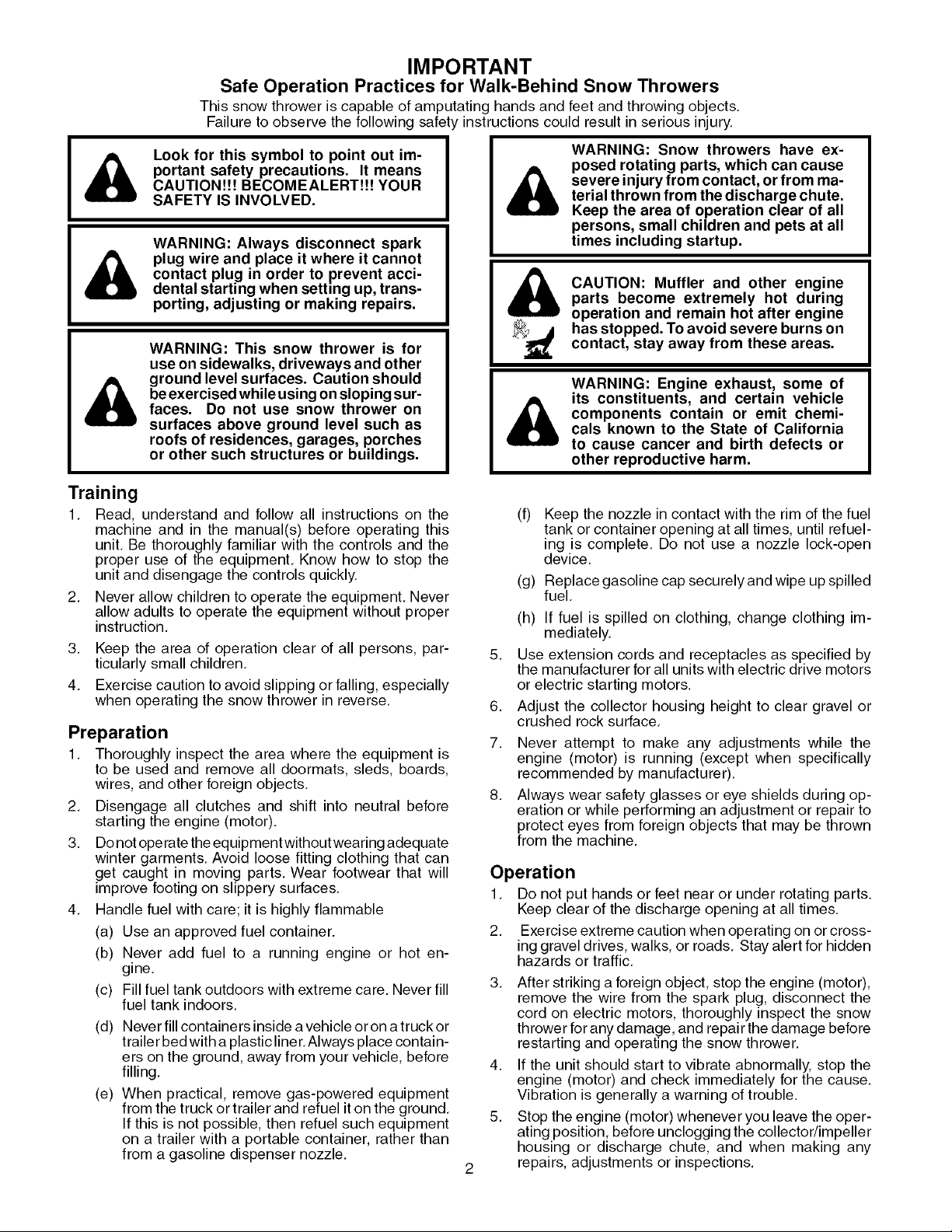
Look for this symbol to point out im-
portant safety precautions. It means
CAUTION!!! BECOMEALERT!!! YOUR
SAFETY IS INVOLVED.
WARNING: Always disconnect spark
plug wire and place it where it cannot
contact plug in order to prevent acci-
dental starting when setting up, trans-
porting, adjusting or making repairs.
WARNING: This snow thrower is for
use on sidewalks, driveways and other
ground level surfaces. Caution should
beexercised while using onsloping sur-
faces. Do not use snow thrower on
surfaces above ground level such as
roofs of residences, garages, porches
or other such structures or buildings.
Training
1, Read, understand and follow all instructions on the
machine and in the manual(s) before operating this
unit, Be thoroughly familiar with the controls and the
proper use of the equipment, Know how to stop the
unit and disengage the controls quickly.
2, Never allow children to operate the equipment. Never
allow adults to operate the equipment without proper
instruction,
3, Keep the area of operation clear of all persons, par-
ticularly small children,
4. Exercise caution to avoid slipping or falling, especially
when operating the snow thrower in reverse,
Preparation
1, Thoroughly inspect the area where the equipment is
to be used and remove all doormats, sleds, boards,
wires, and other foreign objects,
2, Disengage all clutches and shift into neutral before
starting the engine (motor),
3, Do not operate the equipment without wearing adequate
winter garments, Avoid loose fitting clothing that can
get caught in moving parts. Wear footwear that will
improve footing on slippery surfaces,
4, Handle fuel with care; it is highly flammable
(a) Use an approved fuel container.
(b) Never add fuel to a running engine or hot en-
gine.
(c) Fill fuel tank outdoors with extreme care, Never fill
fuel tank indoors,
(d) Never fill containers inside a vehicle oronatruck or
trailer bed with a plastic liner,Always place contain-
ers on the ground, away from your vehicle, before
filling,
(e) When practical, remove gas-powered equipment
from the truck or trailer and refuel iton the ground,
If this is not possible, then refuel such equipment
on a trailer with a portable container, rather than
from a gasoline dispenser nozzle,
WARNING: Snow throwers have ex-
posed rotating parts, which can cause
severe injury from contact, or from ma-
&
&
(f) Keep the nozzle in contact with the rim of the fuel
(g) Replace gasoline cap securely and wipe up spilled
(h) If fuel is spilled on clothing, change clothing im-
5,
Use extension cords and receptacles as specified by
the manufacturer for all units with electric drive motors
or electric starting motors.
6,
Adjust the collector housing height to clear gravel or
crushed rock surface,
7,
Never attempt to make any adjustments while the
engine (motor) is running (except when specifically
recommended by manufacturer),
8,
Always wear safety glasses or eye shields during op-
eration or while performing an adjustment or repair to
protect eyes from foreign objects that may be thrown
from the machine,
terial thrown from the discharge chute.
Keep the area of operation clear of all
persons, small children and pets at all
times including startup.
CAUTION: Muffler and other engine
parts become extremely hot during
operation and remain hot after engine
has stopped. To avoid severe burns on
contact, stay away from these areas.
WARNING: Engine exhaust, some of
its constituents, and certain vehicle
components contain or emit chemi-
cals known to the State of California
to cause cancer and birth defects or
other reproductive harm.
tank or container opening at all times, until refuel-
ing is complete, Do not use a nozzle lock-open
device,
fuel.
mediately.
Operation
1, Do not put hands or feet near or under rotating parts.
Keep clear of the discharge opening at all times.
2, Exercise extreme caution when operating on or cross-
ing gravel drives, walks, or roads. Stay alert for hidden
hazards or traffic,
3, After striking a foreign object, stop the engine (motor),
remove the wire from the spark plug, disconnect the
cord on electric motors, thoroughly inspect the snow
thrower for any damage, and repair the damage before
restarting and operating the snow thrower.
4. If the unit should start to vibrate abnormally, stop the
engine (motor) and check immediately for the cause.
Vibration is generally a warning of trouble.
5. Stop the engine (motor) whenever you leave the oper-
ating position, before unclogging the collector/impeller
housing or discharge chute, and when making any
repairs, adjustments or inspections.
6, Whencleaning,repairingorinspectingthesnowthrower,
stoptheengineandmakecertainthecollector/impeller
andallmovingpartshavestopped,Disconnectthe
sparkplugwireandkeepthewireawayfromtheplug
topreventsomeonefromaccidentallystartingtheen-
gine.
7. Donotruntheengineindoors,exceptwhenstarting
theengineandfortransportingthesnowthrowerinor
outofthebuilding,Opentheoutsidedoors;exhaust
fumesaredangerous,
8. Exerciseextremecautionwhenoperatingonslopes.
9, Neveroperatethesnowthrowerwithoutproperguards,
andothersafetyprotectivedevicesinplaceandwork-
ing.
10,Neverdirectthedischargetowardpeopleorareas
wherepropertydamagecanoccur. Keepchildren
andothersaway.
11,Donotoverloadthemachinecapacitybyattempting
toclearsnowattoofasta rate,
12.Neveroperatethemachineathightransportspeeds
onslipperysurfaces,Lookbehindandusecarewhen
operatinginreverse,
13,Disengagepowertothecollector/impellerwhensnow
throweristransportedornotinuse,
14,Useonlyattachmentsandaccessoriesapprovedby
themanufacturerofthesnowthrower(suchaswheel
weights,counterweights,orcabs).
15.Neveroperatethesnowthrowerwithoutgoodvisibility
orlight,Alwaysbesureofyourfooting,andkeepafirm
holdonthehandles,Walk;neverrun,
16,Nevertoucha hotengineormuffler,
Clearing a Clogged Discharge Chute
Hand contact with the rotating impeller inside the discharge
chute is the most common cause of injury associated with
snow throwers, Never use your hand to clean out the dis-
charge chute, To clear the chute:
1, SHUT THE ENGINE OFF!
2, Wait 10 seconds to be sure the impeller blades have
stopped rotating,
3, Always use a clean-out tool, not your hands.
Maintenance and Storage
1, Check shear bolts and other bolts at frequent intervals
for proper tightness to be sure the equipment is insafe
working condition,
2, Never store the machine with fuel in the fuel tank
inside a building where ignition sources are present
such as hot water heaters, space heaters, or clothes
dryers. Allow the engine to cool before storing in any
enclosure,
3. Always refer to operator's manual for important details
if the snow thrower is to be stored for an extended
period,
4. Maintain or replace safety and instruction labels, as
necessary,
5, Run the machine a few minutes after throwing snow
to prevent freeze-up of the collector/impeller.
CONGRATULATIONS on your purchase of a new snow
thrower, Ithasbeen designed, engineered and manufactured
to give best possible dependability and performance,
Should you experience any problem you cannot easily
remedy, please contact your nearest authorized service
center. We have competent, well-trained technicians and
the proper tools to service or repair this unit,
Please read and retain this manual, The instructions will
enable you to assemble and maintain your snow thrower
properly. Always observe the "SAFETY RULES",
SERIAL NUMBER:
DATE OF PURCHASE:
THE MODELAND SERIAL NUMBERSWILL BE FOUND
ONA DECALATTACHEDTOTHE REAR OFTHE SNOW
THROWER HOUSING,
YOU SHOULD RECORD BOTH SERIAL NUMBER AND
DATE OF PURCHASE AND KEEP IN A SAFE PLACE
FOR FUTURE REFERENCE,
TABLE OF CONTENTS
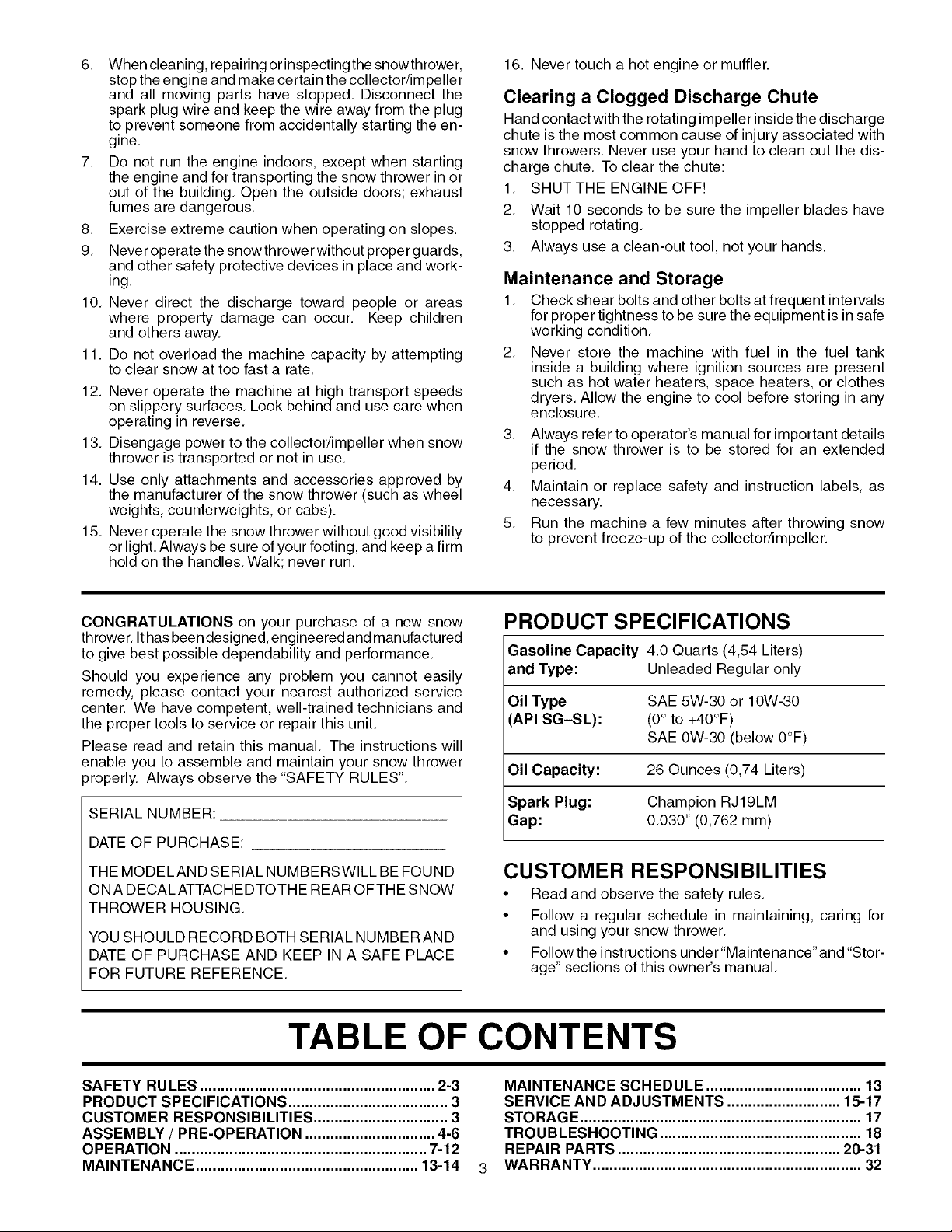
PRODUCT SPECIFICATIONS
Gasoline Capacity 4.0 Quarts (4,54 Liters)
and Type: Unleaded Regular only
Oil Type SAE 5W-30 or 10W-30
API SG-SL): (0° to +40°F)
SAE 0W-30 (below 0°F)
Oil Capacity: 26 Ounces (0,74 Liters)
Spark Plug: Champion RJ19LM
Gap: 0,030" (0,762 ram)
CUSTOMER RESPONSIBILITIES
• Read and observe the safety rules,
• Follow a regular schedule in maintaining, caring for
and using your snow thrower.
• Follow the instructions under"Maintenance"and "Stor-
age" sections of this owner's manual,
SAFETY RULES ........................................................ 2-3
PRODUCT SPECIFICATIONS ...................................... 3
CUSTOMER RESPONSIBILITIES ................................ 3
ASSEMBLY / PRE-OPERATION ............................... 4-6
OPERATION ............................................................ 7-12
MAINTENANCE ..................................................... 13-14
MAINTENANCE SCHEDULE ..................................... 13
SERVICE AND ADJUSTMENTS ........................... 15-17
STORAGE ................................................................... 17
TROUBLESHOOTING ................................................ 18
REPAIR PARTS ..................................................... 20-31
WARRANTY ................................................................ 32
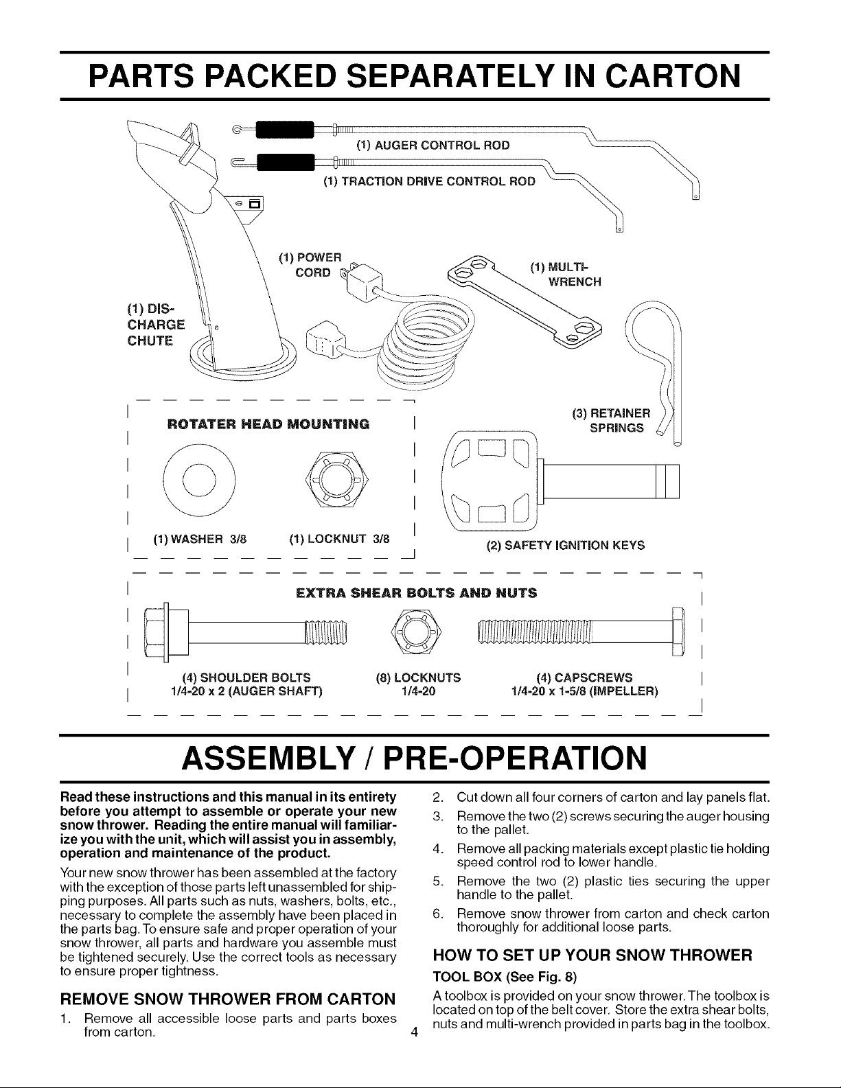
PARTS PACKED SEPARATELY IN CARTON
(1) AUGER CONTROL ROD
(1) TRACTION DRIVE CONTROL ROD
(1)POWER
CORD
(1)DIS-
CHARGE
CHUTE
ROTATER HEAD MOUNTING I
(1)WASHER 3/8 (1) LOCKNUT 3/8
EXTRA SHEAR BOLTS AND HUTS
I
I
I
J
©
(1)MULTI=
WRENCH
(3) RETAINER
SPRINGS
(2) SAFETYiGNiTiON KEYS
]
I
I
I
(4) SHOULDERBOLTS
1/4=20x 2 (AUGERSHAFT)
(8) LOCKNUTS
ASSEMBLY / PRE-OPERATION
Read these instructions and this manual in its entirety
before you attempt to assemble or operate your new
snow thrower. Reading the entire manual will familiar-
ize you with the unit, which will assist you in assembly,
operation and maintenance of the product.
Your new snow thrower has been assembled at the factory
with the exception of those parts left unassembled for ship-
ping purposes, All parts such as nuts, washers, bolts, etc,,
necessary to complete the assembly have been placed in
the parts bag. To ensure safe and proper operation of your
snow thrower, all parts and hardware you assemble must
be tightened securely, Use the correct tools as necessary
to ensure proper tightness.
REMOVE SNOW THROWER FROM CARTON
1. Remove all accessible loose parts and parts boxes
from carton,
1!4-20
2, Out down all four corners of carton and lay panels flat,
3, Remove the two (2) screws securing the auger housing
to the pallet,
4. Remove all packing materials except plastic tie holding
speed control rod to lower handle.
5, Remove the two (2) plastic ties securing the upper
handle to the pallet.
6, Remove snow thrower from carton and check carton
thoroughly for additional loose parts,
(4) CAPSCREWS
1/4=20 x 1=5/8 (IMPELLER)
HOW TO SET UP YOUR SNOW THROWER
TOOL BOX (See Fig. 8)
A toolbox is provided onyour snow thrower.The toolbox is
located on top of the belt cover. Store the extra shear bolts,
nuts and multi-wrench provided in parts bag in the toolbox.
I
I
ASSEMBLY / PRE-OPERATION
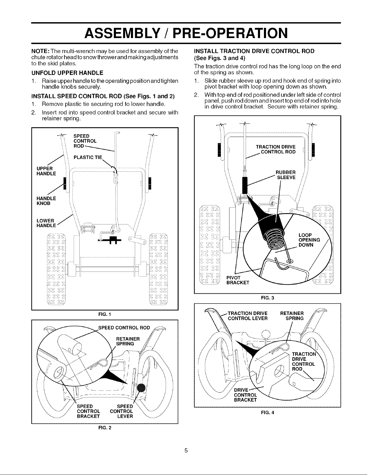
NOTE: The multi-wrench may be used for assembly of the
chute rotator head to snow throwerand making adjustments
to the skid plates.
UNFOLD UPPER HANDLE
1, Raise upper handle to the operating position and tighten
handle knobs securely.
INSTALL SPEED CONTROL ROD (See Figs. 1 and 2)
1, Remove plastic tie securing rod to lower handle,
2, Insert rod into speed control bracket and secure with
retainer spring,
SPEED
CONTROL i
',, ,,,
LOWER
HANDLE
INSTALL TRACTION DRIVE CONTROL ROD
(See Figs. 3 and 4)
The traction drive control rod has the long loop on the end
of the spring as shown.
1. Slide rubber sleeve up rod and hook end of spring into
pivot bracket with loop opening down as shown,
2. With top end of rod positioned under left side of control
panel, push rod down and insert top end of rod into hole
in drive control bracket, Secure with retainer spring,
FIG. 1
SPEED CONTROL ROD
RETAINER
SPRING
SPEED SPEED
CONTROL CONTROL
BRACKET LEVER
FIG. 2
FIG. 3
)N DRIVE RETAINER
SPRING
CONTROL
BRACKET
FIG. 4
ASSEMBLY / PRE-OPERATION
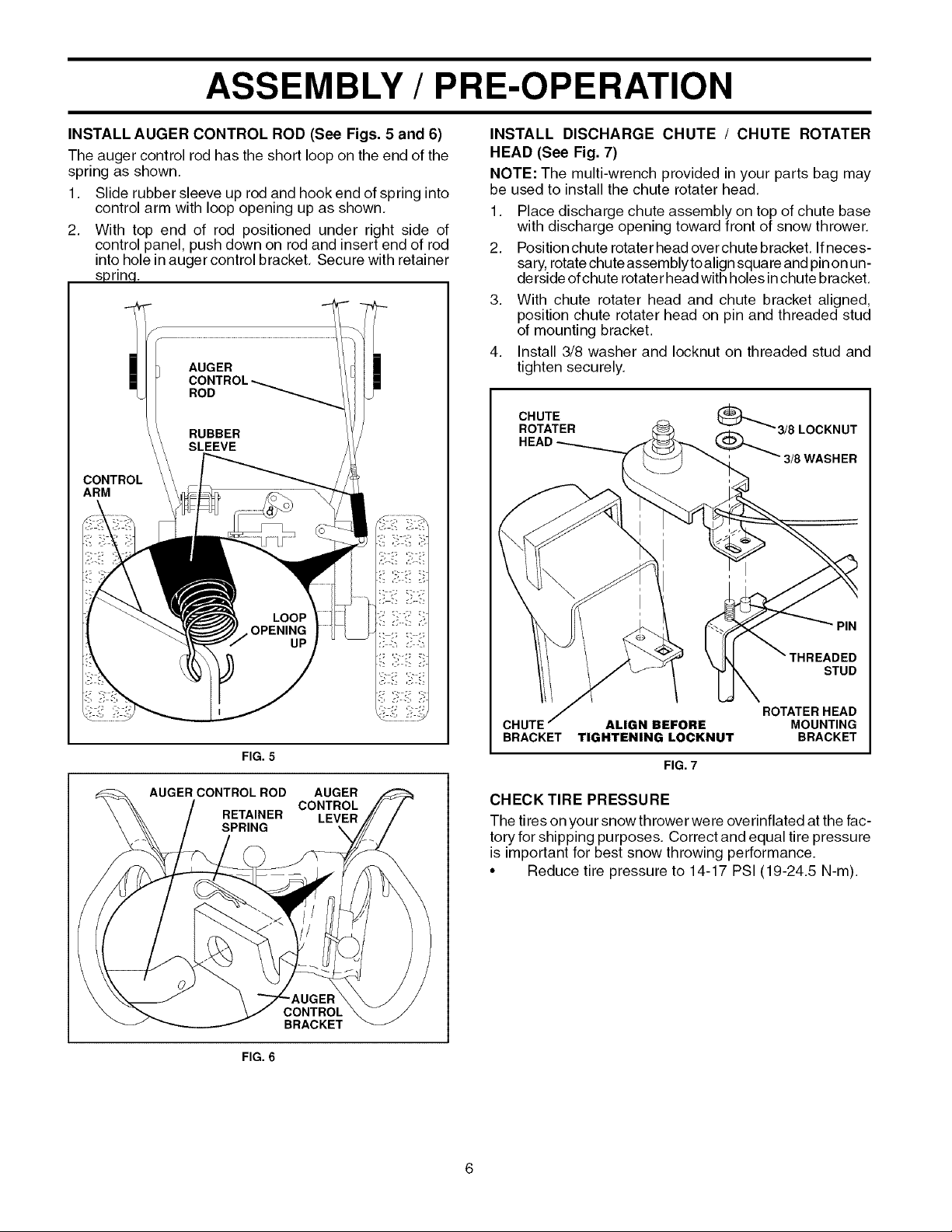
INSTALL AUGER CONTROL ROD (See Figs. 5 and 6)
The auger control rod has the short loop on the end of the
spring as shown.
1. Slide rubber sleeve up rod and hook end of spring into
control arm with loop opening up as shown,
2. With top end of rod positioned under right side of
control panel, push down on rod and insert end of rod
into hole in auger control bracket, Secure with retainer
sprinq.
i
\
CONTROL
ARM
INSTALL DISCHARGE CHUTE / CHUTE ROTATER
HEAD (See Fig. 7)
NOTE: The multi-wrench provided in your parts bag may
be used to install the chute rotater head,
1. Place discharge chute assembly on top of chute base
with discharge opening toward front of snow thrower,
2. Positionchuterotaterheadoverchutebracket. Ifneces-
sary,rotate chute assembly to align squareand pinon un-
derside of chute rotate rhead with holes inchute bracket.
3. With chute rotater head and chute bracket aligned,
position chute rotater head on pin and threaded stud
of mounting bracket.
4. Install 3/8 washer and Iocknut on threaded stud and
tighten securely.
CHUTE
ROTATER
HEAD
_3/8LOCKNUT
(_)_3/8WASHER
FIG. 5
AUGER CONTROLROD AUGER
RETAINER LEVER
SPRING \
FIG. 6
CONTROL
CONTROL
BRACKET
PIN
STUD
ROTATER HEAD
CHUTE ALIGN BEFORE MOUNTING
BRACKET TIGMTENING LOCKNMT BRACKET
FIG. 7
CHECK TIRE PRESSURE
The tires on your snow thrower were overinflated at the fac-
tory for shipping purposes. Correct and equal tire pressure
is important for best snow throwing performance.
• Reduce tire pressure to 14-17 PSI (19-24,5 N-m).
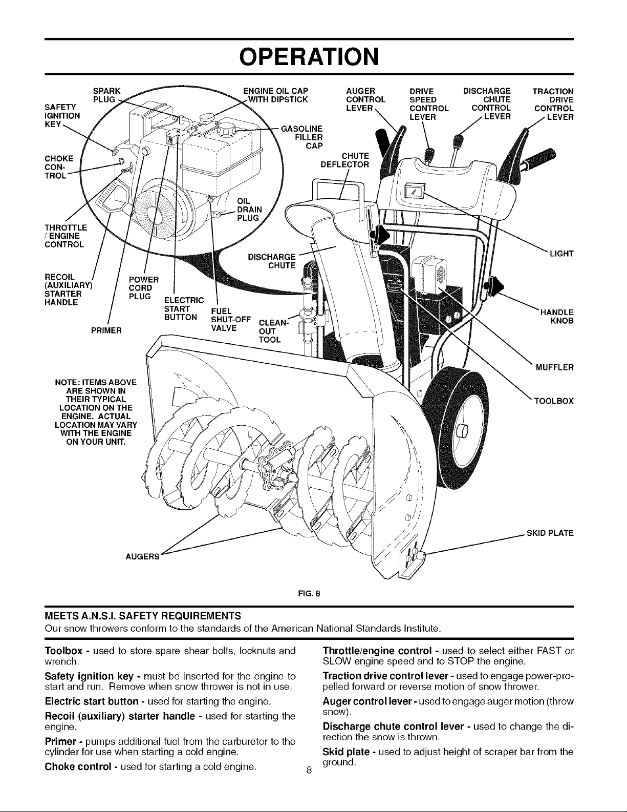
OPERATION
KNOW YOUR SNOW THROWER
READ THIS OWNER'S MANUAL AND ALL SAFETY RULES BEFORE OPERATING YOUR SNOW THROWER. Compare
the illustrations with your snow thrower to familiarize yourself with the location of various controls and adjustments. Save
this manual for future reference.
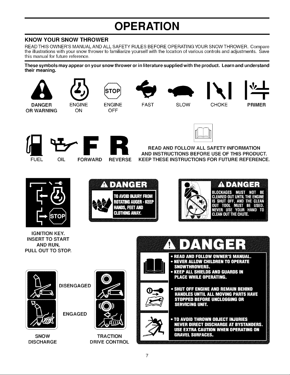
These symbols may appear on your snow thrower or in literature supplied with the product. Learn and understand
their meaning.
r
DANGER ENGINE FAST SLOW CHOKE PRIMER
OR WARNING ON
FUEL OIL FORWARD REVERSE
ENGINE
OFF
READ AND FOLLOW ALL SAFETY iNFORMATiON
AND iNSTRUCTiONS BEFORE USE OF THiS PRODUCT.
KEEP THESE iNSTRUCTiONS FOR FUTURE REFERENCE.
I\1
iGNiTiON KEY.
iNSERT TO START
AND RUN,
PULL OUT TO STOP.
DISENGAGED
ENGAGED
SNOW
DISCHARGE
TRACTION
DRIVE CONTROL
OPERATION
SPARK
SAFETY
IGNITION
CHOKE
CON-
TR_
THROTTLE
/ ENGINE
CONTROL
RECOIL
(AUXILIARY)
STARTER
HANDLE
PRIMER
NOTE: ITEMS ABOVE
ARE SHOWN IN
THEIR TYPICAL
LOCATION ON THE
ENGINE. ACTUAL
LOCATION MAY VARY
WITH THE ENGINE
ON YOUR UNIT.
POWER
CORD
PLUG
ELECTRIC
START
BUTTON
ENGINE OIL CAP AUGER
DIPSTICK CONTROL
OIL
PLUG
DIS(
CHUTE
FUEL
SHUT-OFF CLEAN-
VALVE OUT
TOOL
GASOLINE
FILLER
CAP
CHUTE
DEFLECTOR
DRIVE
SPEED
CONTROL
LEVER
DISCHARGE
CHUTE
CONTROL
TRACTION
DRIVE
CONTROL
LEVER
LIGHT
HANDLE
KNOB
MUFFLER
rOOLBOX
AUGERS
FIG.8
MEETS A.N.S.I. SAFETY REQUIREMENTS
Our snow throwers conform to the standards of the American National Standards Institute.
Toolbox - used to store spare shear bolts, locknuts and
wrench,
Safety ignition key - must be inserted for the engine to
start and run, Remove when snow thrower is not in use,
Electric start button - used for starting the engine,
Recoil (auxiliary) starter handle - used for starting the
engine.
Primer - pumps additional fuel from the carburetor to the
cylinder for use when starting a cold engine.
Choke control - used for starting a cold engine.
Throttle/engine control - used to select either FAST or
SLOW engine speed and to STOP the engine,
Traction drive control lever -used to engage power-pro-
pelled forward or reverse motion of snow thrower.
Auger control lever -used to engage auger motion (throw
snow).
Discharge chute control lever - used to change the di-
rection the snow is thrown.
Skid plate - used to adjust height of scraper bar from the
ground,
PLATE
OPERATION
The operation of any snow thrower can result
in foreign objects thrown into the eyes, which
can result in severeeye damage Always wear
safety glasses or eye shields while operating
your snow thrower or performing any adjust-
ments or repairs We recommend standard safety glasses
or a wide vision safety mask worn over spectacles
HOW TO USE YOUR SNOW THROWER
Know how to operate all controls before adding fuel or
attempting to start the engine
STOPPING
TRACTION DRIVE
• Release traction drive control lever to stop the forward
or reverse movement of the snow thrower
AUGER
• Release the auger control lever to stop throwing snow
ENGINE
1 Move throttle control to "STOP" position
2 Remove (do not turn) safety ignition key to prevent
unauthorized use
NOTE: Never use choke to stop engine
TO USE FUEL SHUT-OFF VALVE (See Fig. 9)
The fuel shut-off valve is located beneath the fuel tank on
the engine Always operate the snow thrower with the fuel
shut-off valve in the OPEN position
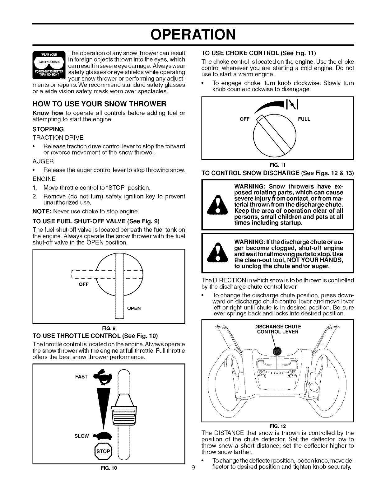
TO USE CHOKE CONTROL (See Fig. 11)
The choke control is located on the engine, Use the choke
control whenever you are starting a cold engine, Do not
use to start a warm engine,
• To engage choke, turn knob clockwise, Slowly turn
knob counterclockwise to disengage.
FULL
FIG. 11
TO CONTROL SNOW DISCHARGE (See Figs. 12 & 13
WARNING: Snow throwers have ex-
posed rotating parts, which can cause
severe injury from contact, or from ma-
terial thrown from the discharge chute.
Keep the area of operation clear of all
persons, small children and pets at all
times including startup.
WARNING: Ifthe discharge chute or au-
ger become clogged, shut-off engine
and waitfor all moving parts tostop. Use
the clean-out tool, NOT YOUR HANDS,
to unclog the chute and/or auger.
OPEN
FIG. 9
TO USE THROTTLE CONTROL (See Fig. 10)
The throttle control islocated on the engine Always operate
the snow thrower with the engine at full throttle Full throttle
offers the best snow thrower performance
FAST
SLOW
Q
FIG. 10
The DIRECTION in which snow isto be thrown iscontrolled
by the discharge chute control lever
• To change the discharge chute position, press down-
ward on discharge chute control lever and move lever
left or right until chute is in desired position Be sure
lever springs back and locks into desired position
DISCHARGE CHUTE
CONTROLLEVER
FIG. 12
The DISTANCE that snow is thrown is controlled by the
position of the chute deflector Set the deflector low to
throw snow a short distance; set the deflector higher to
throw snow farther
• Tochange the deflector position, loosen knob, move de-
flector to desired position and tighten knob securely
OPERATION
HIGH POSITION
\
\
I
I
\
//_!l
×_-.I
Z/Y//\\
\
I
I KNOB
CHUTE
DEFLECTOR
LOW POSITION
FIG. 13
TO THROW SNOW (See Fig. 14)
The auger rotation is controlled by the auger control lever
located on the right side handle.
• Squeeze auger control lever to handle to engage the
auger and throw snow.
• Release the auger control lever to stop throwing snow,
DISCHARGE CHUTE
TOOL
FIG. 15
TO MOVE FORWARD AND BACKWARD (See Fig. 16)
SELF-PROPELLING, forward and reverse movement of
the snow thrower, is controlled by the traction drive control
lever located on the left side handle.
• Squeeze traction drive control lever to handle to engage
the drive system.
• Release traction drive control lever to stop the forward
or reverse movement of the snow thrower.
SPEED and DIRECTION arecontrolled by the drive speed
control lever,
Press downward on the speed control lever and move
lever to desired position BEFORE engaging the trac-
tion drive control lever.Be sure lever springs back and
locks into desired position,
FIG. 14
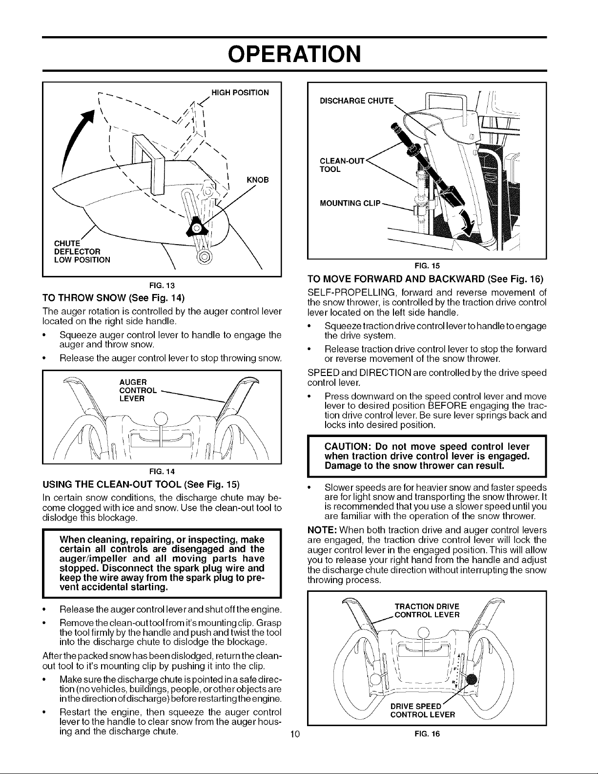
USING THE CLEAN-OUT TOOL (See Fig. 15)
In certain snow conditions, the discharge chute may be-
come clogged with ice and snow. Use the clean-out tool to
dislodge this blockage.
When cleaning, repairing, or inspecting, make
certain all controls are disengaged and the
auger/impeller and all moving parts have
stopped. Disconnect the spark plug wire and
keep the wire away from the spark plug to pre-
vent accidental starting.
• Release the auger control lever and shut off the engine.
• Remove the clean-out tool from it's mounting clip, Grasp
the tool firmly by the handle and push and twist the tool
into the discharge chute to dislodge the blockage,
After the packed snow has been dislodged, return the clean-
out tool to it's mounting clip by pushing it into the clip,
• Makesurethe discharge chute is pointed ina safe direc-
tion (no vehicles, buildings, people, or other objects are
inthe direction of discharge) before restarting the engine.
• Restart the engine, then squeeze the auger control
lever to the handle to clear snow from the auger hous-
ing and the discharge chute.
when traction drive control lever is engaged.
I AUTION: Do not move speed control lever
Damage to the snow thrower can result.
• Slower speeds are for heavier snow and faster speeds
are for light snow and transporting the snow thrower. It
is recommended that you use a slower speed until you
are familiar with the operation of the snow thrower,
NOTE: When both traction drive and auger control levers
are engaged, the traction drive control lever will lock the
auger control lever in the engaged position, This will allow
you to release your right hand from the handle and adjust
the discharge chute direction without interrupting the snow
throwing process.
TRACTION DRIVE
DRIVE
CONTROL LEVER
10 FIG. 16
LEVER
 Loading...