

Poulan 917279710 Owner’s Manual
IMPORTANT MANUAL Do Not Throw Away
TM
ASSEMBLY/REPAIR PARTS MANUAL
MODEL:
Read thee WARNING:
and follow all Warnings and
Safety Instructions. Failure to
917.279710
do so can result in serious
injury.
LAWN TRACTOR
Always Wear Eye Protection During Operation
279710
Operator's Manual
169087 2.16.99 JH
Printed in U.S.A.

SAFETY RULES
,,,%
Safe Operation Practices for Ride-On Mowers
IMPORTANT: THIS CUTTING MACHINE IS CAPABLE OF AMPUTATING HANDS AND FEET AND THROWING OBJECTS
,_" :-/_"FQ OBSERVE THE FOLLOWII_-ETY INSTRUCT4ONS_=COULD4RESU_:T_|N SERIOUS INJUF_W-,OR_D,E_AZ.._
L GENERAL OPERATION
Read, understand, and follow all instructions inthe manual
and on the machine before starting.
Only allow responsible adults, who are familiar with the in-
structions, to operate the machine.
Cle_.r the area of objects such as rocks, toys, wire, etc.,
which could be picked up and thrown by the blade.
Be sure the area is clear of other people before mowing.
Stop machine if anyone enters the area.
Never carry passengers.
Do not mow in reverse unless absolutely necessary.
Always look down and behind before and while backing.
Be aware of the mower discharge direction and do not point
it at anyone. Do not operate the mower w_thout either the
entire grass catcher or the guard in place.
Slow down before turning.
Never leave a running machine unattended. Always turn
off blades, set parking brake, stop engine, .:nd remove
keys before dismounting.
Turn off blades when not mowing.
Stop .engine before removing grass catcher or unclogging
chute.
Mow only in daylight or good artificial light.
De not operate the machine while under the influence of
alcohol or drugs.
Watch for traffic when operating near or crossing roadways.
Use extra care when loading or unloading the machine into
a trailer or truck.
II. SLOPE OPERATION
Slopes are a major factor related to loss-of-control and
tipover accidents, which can result in severe injury or
death. All slopes require extra caution. If you cannot
back up the slope or if you feel uneasy on it, do not mow
it.
DO:
Mow up and down slopes, not across.
Remove obstacles such as rocks, tree limbs, etc.
Watch for holes, ruts, or bumps. Uneven terrain could
overturn the machine. Tallgrass can hide obstacles.
Use slow speed. Choose a low gear so that you will not
have to stop or shift while on the slope•
Fellow the manufacturer's recommendations for wheel
weights or counterweights to improve stability.
Use extra care with grass catchers or other attachments.
These can change the stability ofthe machine•
Keep all movement on the slopes slowand gradual De not
make sudden changes in speed or direction.
Avoid starting or stopping on a slope. If tires lose traction,
disengage the blades and proceed slowly straight down the
slope.
DO NOT:
Do not turn on slopes unless necessary, and then, turn
slowly and-gradually downhill, _f possible.
Do'notmow near drop-offs, ditches, or embankments. The
mower could suddenly turn over if a wheel is over the edge
of a cliff or ditch, or if an edge caves in.
Do not mow on wet grass. Reduced traction could cause
sliding.
Do not try to stabilize the machine by putting your foot on
the ground.
Do not use grass catcher' on steep slopes.
Ill. CHILDREN
Tragic accidents can occur if the operator is not alert to
the presence of children. Children are often attracted to
the machine and the mowing activity. Never assume that
children will remain where you last saw them.
Keep children out of the mowing area and under the watch-
ful care of another responsible adult.
Be alert and turn machine offif children enter the area.
Before and when backing, look behind and down for small
children.
Never carry children. They may fail off and be seriously
injured or interfere with safe machine operation.
Never aUow children to operate the machine.
Use extra care when approaching blind corners, shrubs,
trees, or.other objects that may obscure vision.
IV. SERVICE
Use extra care in.handling gasoline and other fuels. They
are flammable and vapors are explosive,
Use only an approved container.
Never remove gas cap or add fuel with the engine run-
ning. Allow engine to cool before refueling, Do not
smoke•
Never refuel the machine indoors,
Never stere the machine or fuel container inside where
there is an open flame, such as a water heater.
Never run a machine inside a closed area.
• Keep nuts end bolts, especially blade attachment bolts,
tight and keep equipment in good condition.
• Never tamper with safety devices. Check their proper op-
eration regularly.
.• Keep machine free of grass, leaves, or other debris build-
up. Clean oil or fuel spillage. Allow machine to cool before
storing.
Stop and inspect the equipment if you strike an abject.
Repair, if necessary, before restarting.
• Never make adjustments or repairs with the engine run-
ning.
Grass catcher components are subject to wear, damage,
and deterioration, which could expose moving parts or
allow objects to be thrown. Frequently check components
and replace with manufacturer's recommended parts, when
necessary.
Mower blades are sharp and can cut. Wrap the blade(s) or
wear gloves, and use extra caution when servicing them.
Check brake operation frequently. Adjust and service as
required.
Look for this symbol to point out im-
portant safety precautions. It means
&
CAUTION!t! BECOME ALERT!!!
YOUR SAFETY IS INVOLVED.
CAUTION: Always disconnect spark plug
wire and place wire where it cannot con-
&
tact spark plug In order to prevent acci-
dental starting when setting up, transport-
ing, adjusting or making repairs.
WARNING
The engineexhaust from this product con-
tains chemmals known to the State of Cali-
fornia to cause cancer, birth defects, or other
reproductive harm.
2
CONGRATULATIONS on your purchase of a New Trac-
tor. It has been designed, engineered and manufactured
to give you the best possible dependability and per'for-
.manGe.
Should you experience any problem you cannot easily
remedy, please contact your nearest authorized service
center/Department. We have competent, well-trained
technicians and the proper tools to service or repair this
tractor.
Please read and retain.this maouaL The instructions will
enable you to assemble and maintain your tractor prop-
erly. Always observe the "SAFETY RULES".
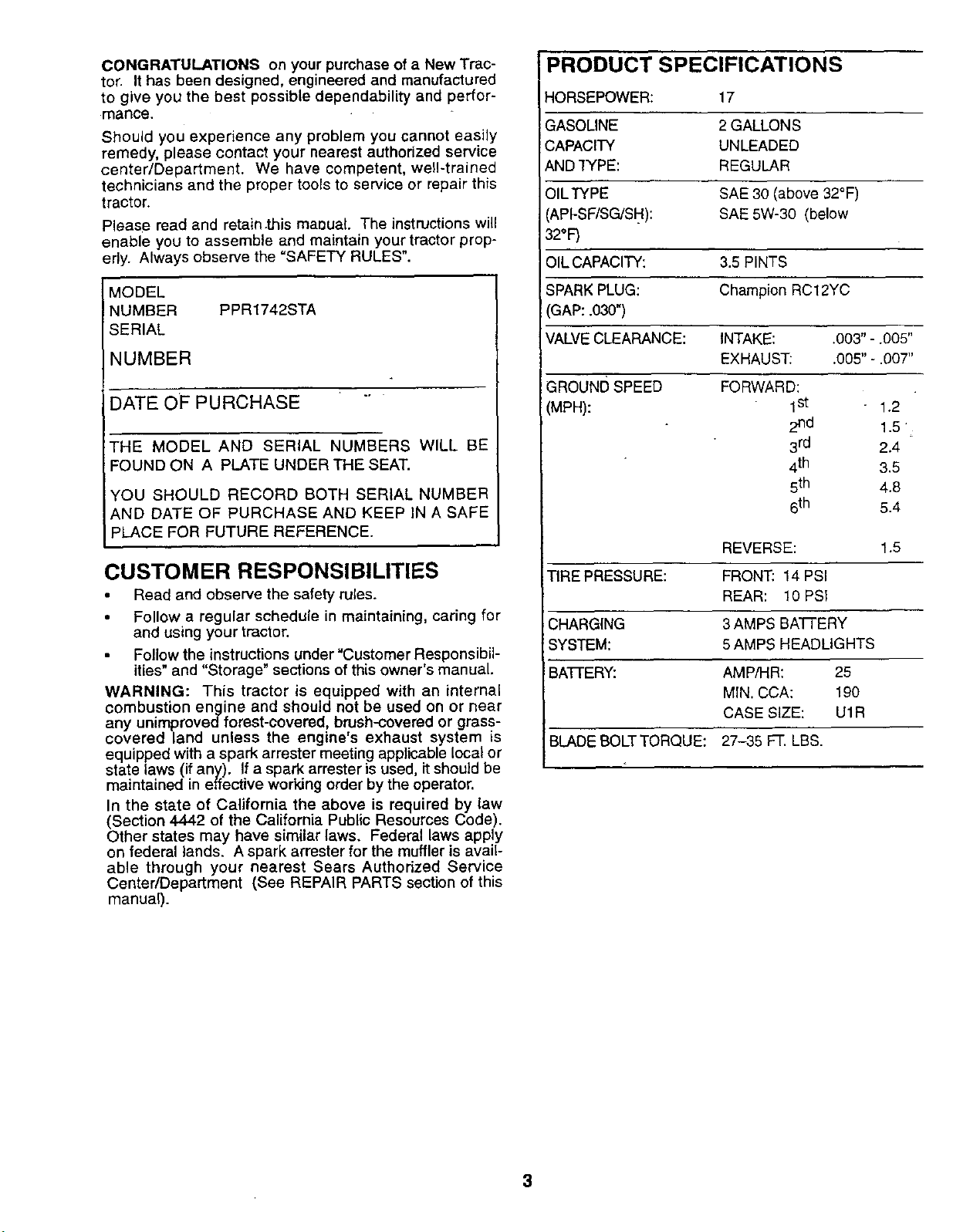
PRODUCT SPECIFICATIONS
HORSEPOWER: 17
GASOLINE 2 GALLONS
CAPACITY UNLEADED
AND "fYPE: REGULAR
OILTYPE SAE 30 (above 32°F)
(API-SF/SG/SH): SAE 5W-30 (below
32oF)
OIL CAPACITY: 3.5 PINTS
MODEL
NUMBER PPR1742STA
SERIAL
NUMBER
DATE OFPURCHASE
THE MODEL AND SERIAL NUMBERS WILL BE
FOUND ON A PLATE UNDER THE SEAT.
YOU SHOULD RECORD BOTH SERIAL NUMBER
AND DATE OF PURCHASE AND KEEP IN A SAFE
PLACE FOR FUTURE REFERENCE.
CUSTOMER RESPONSIBILITIES
Read and observe the safety rules.
• Follow a regular schedule in maintaining, caring for
and using your tractor.
Follow the instructions under =Customer Responsibil-
ities" and "Storage" sections of this owner's manual.
WARNING: This tractor is equipped with an internal
combustion engine and should not be used on or near
any unimprovedforest-covered, brush-covered or grass-
covered land unless the engine's exhaust system is
equipped with a spark arrester meeting applicable local or
state laws (if any). If a spark arrester is used, it should be
maintained in effective working order by the operator.
In the state of California the above is required by law
(Section 4442 of the California Public Resources Code).
Other states may have similar laws. Federal laws apply
on federal lands. A spark arrester for the muffler is avail-
able through your nearest Sears Authorized Service
Center/Department (See REPAIR PARTS section of this
manual).
SPARK PLUG: Champion RC12YC
GAP: .030")
VALVE CLEARANCE: INTAKE: .003" - .005"
EXHAUST: .005" - .007"
GROUND SPEED
(MPH):
TIRE PRESSURE: FRONT: 14 PSI
CHARGING 3AMPS BATTERY
SYSTEM: 5 AMPS HEADLIGHTS
BAFFERY: AMP/HR: 25
BLADE BOLTTORQUE: 27-35 FT. LBS.
FORWARD:
1st 1.2
2nd 1.5
3rd 2.4
4th 3.5
5th 4.8
6th 5.4
REVERSE: 1.5
REAR: 10 PSI
MIN. CCA: 190
CASE SIZE: U1R
3
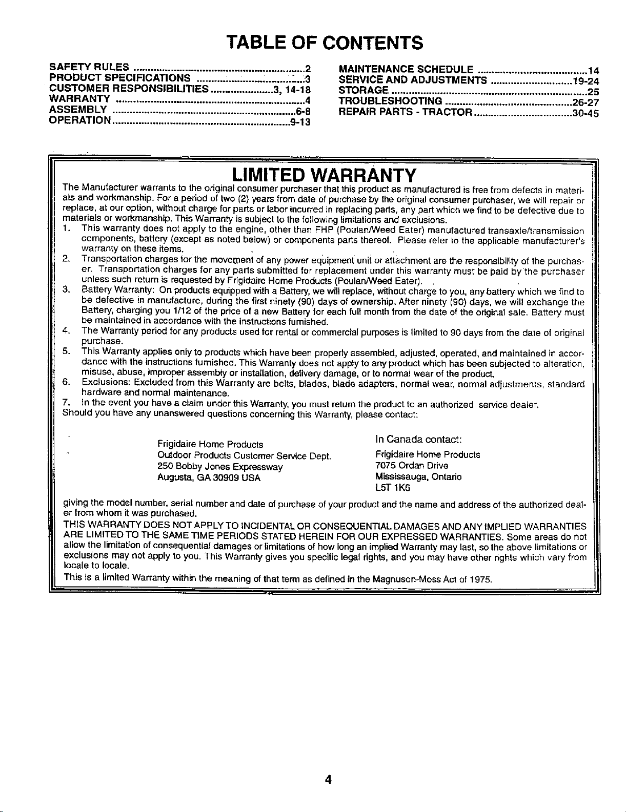
TABLE OF CONTENTS
SAFETY RULES ............................................................ 2
PRODUCT SPECIFICATIONS .......... ;....:.............. ,.....3
CUSTOMER RESPONSIBILITIES ...................... 3, 14-18
WARRANTY .................................................................. 4
ASSEMBLY ................................................................ 6-8
MAINTENANCE SCHEDULE ...................................... 14
SERVICE AND ADJUSTMENTS ............................ 19-24
STORAGE .................................................................... 25
TROUBLESHOOTING ............................................ 26-27
REPAIR PARTS - TRACTOR .................................. 30-45
OPERATION .............................................................. 9-13
LIMITED WARRANTY
The Manufacturer warrants to the original consumer purchaser that thisproduct as manufactured is free from defects in materi-
als and workmanship. For a period of two (2) years from date of purchase by the original consumer purchaser, we will repair or
replace, at our option, without charge for parts or labor incurred in replacing parts, any part which we find to be defective due to
materials or workmanship. This Warranty is subject to the following limitations and exclusions.
1. This warranty does not apply to the engine, other than FHP (Poulan/Weed Eater) manufactured transaxle/transmission
components, battery (except as noted below) or components parts thereof. Please refer to the applicable manufacturer's
warranty on these items.
2. Transportation charges for the movement of any power eq_Jipmen{ unii or attachment are the responsibility of the purchas-
er. Transportation charges for any parts submitted for replacement under this warranty must be paid by the purchaser
unless such return is requested by Frigidaire Home Products (Peulan/Weed Eater). .
3. Battery Warranty: On products equipped with a Battery, we will replace, without charge to you, any battery which we find to
be defective in manufacture, dudng the first ninety (90) days of ownership. After ninety (90) days, we will exchange the
Battery, charging you 1112 of the price of a new Battery for each full month from the date of the odgieal sale. Battery must
be maintained in accordance with the instructions fumished.
4. The Warranty period for any products used for rental or commercial purposes is limited to 90 days from the date of original
purchase.
5. This Warranty applies only to products which have been properly assembled, adjusted, operated, and maintained in accor-
dance with the instructions furnished. This Warranty does not apply to any product which has been subjected to alteration,
misuse, abuse, improper assembly or installation, delivery damage, or to normal wear of the product.
6. Exclusions: Excluded from this Warranty are belts, blades, blade adapters, normal wear, normal adjustments, standard
hardware and normal maintenance.
7. In the event you have a claim under this Warranty, you must return the product to an authorized service dealer.
Should you have any unanswered questions concerning this Warranty, please contact:
Frigidaire Home Products
Outdoor Products Customer Service Dept.
250 Bobby Jones Expressway
Augusta, GA 30909 USA
giving the model number, serial number and date of purchase of your product and the name and address of the authorized deaf
er from whom it was purchased.
THIS WARRANTY DOES NOT APPLY TO INCIDENTAL OR CONSEQUENTIAL DAMAGES AND ANY IMPLIED WARRANTIES
ARE LIMITED TO THE SAME TIME PERIODS STATED HEREIN FOR OUR EXPRESSED WARRANTIES. Some areas rio not
allow the limitation of consequential damages or limitations of how long an implied Warranty may last, so the above limitations or
exclusions may not apply to you. This Warranty gives you specific legal rights, and you may have other rights which vary from
locale to locale.
This is a limited Warranty within the meaning of that term as defined in the Magnuson-Moss Act of 1975.
In Canada contact:
Frigidaire Home Products
7075 Ordan Drive
Mississauga, Ontario
L5T 1K6
4
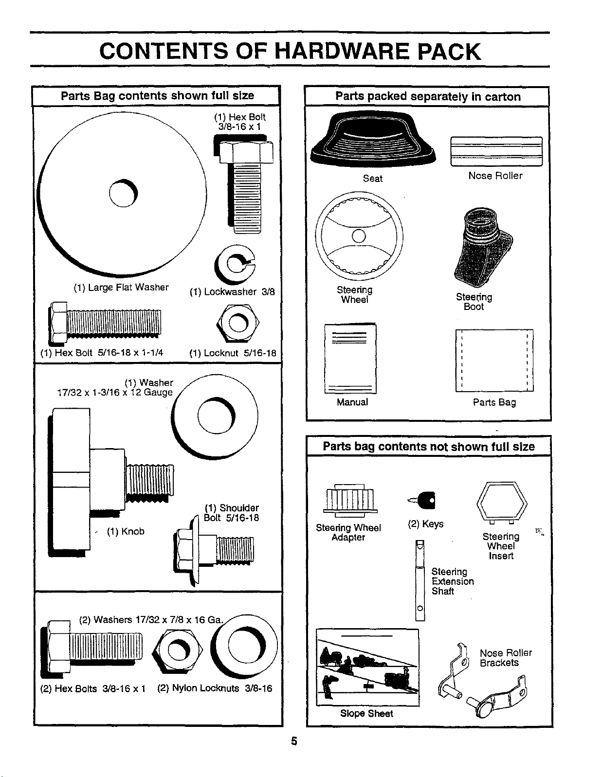
CONTENTS OF HARDWARE PACK
ii ii= iii
Parts Bag contents shown full size
Parts packed separately in carton
(1) Hex Bolt
(1) Large Flat Washer
(1) Hex Bolt 5/16-18 x 1-1/4
(1) Washer
17/32 x 1-3/16 x 12 Gauge// _
(1) Lockwasher 3/8
(1) koeknut 5/18-18
k2/
3/8-16 li_
@
Seat
Steering
Wheel
Manual
Parts bag contents not shown full size
Nose Roller
Steering
Boot
Parts Bag
N
(1) Shoulder
Bolt 5/16-18
(1) Knob
(2) Hex Bolts 3/8-16 x 1 (2) Nylon Locknuts 3/8-16
SteedngWheel (2) Keys
Adapter Steenng
Insert
Steedng
E_ension
Shaft
t Wheel
Nose Roller
Brackets
Slope Sheet
5
ASSEMBLY
Your new tractor has been assembled at the factory with exception ofthose parts left unassembled for shipping purposes.
To ensure safe and proper operation of your tractor all parts and hardware you assemble must be tightened securely. Use
the correct tools as necessary to insure proper tightness.
TOOLS REQUIRED FOR ASSEMBLY
A socket wrench set will make assembly easier. Standard
wrench sizes are listed.
(1) 3/4" Socket w/drive rachet Utility knife
(1) 9/16" wrench Tire pressure gauge
(2) 1/2" wrenches Phillips Screwdriver
When right or left hand is mentioned in this manual, it
means when you are in the operating position (seated
behind the steering wheel).
TO REMOVE TRACTOR FROM CARTON
UNPACK CARTON
Remove all accessible loose parts and parts cartons
from carton (See page 5).
• Cut, from top to bottom, along lines on all four comers
of carton, and lay panels flat.
Check for any additional loose parts or cartons and
remove.
BEFORE ROLLING TRACTOR OFF SKID
STEERING
WHEEL
STEERING
BOOT
TABS
ADAPTER
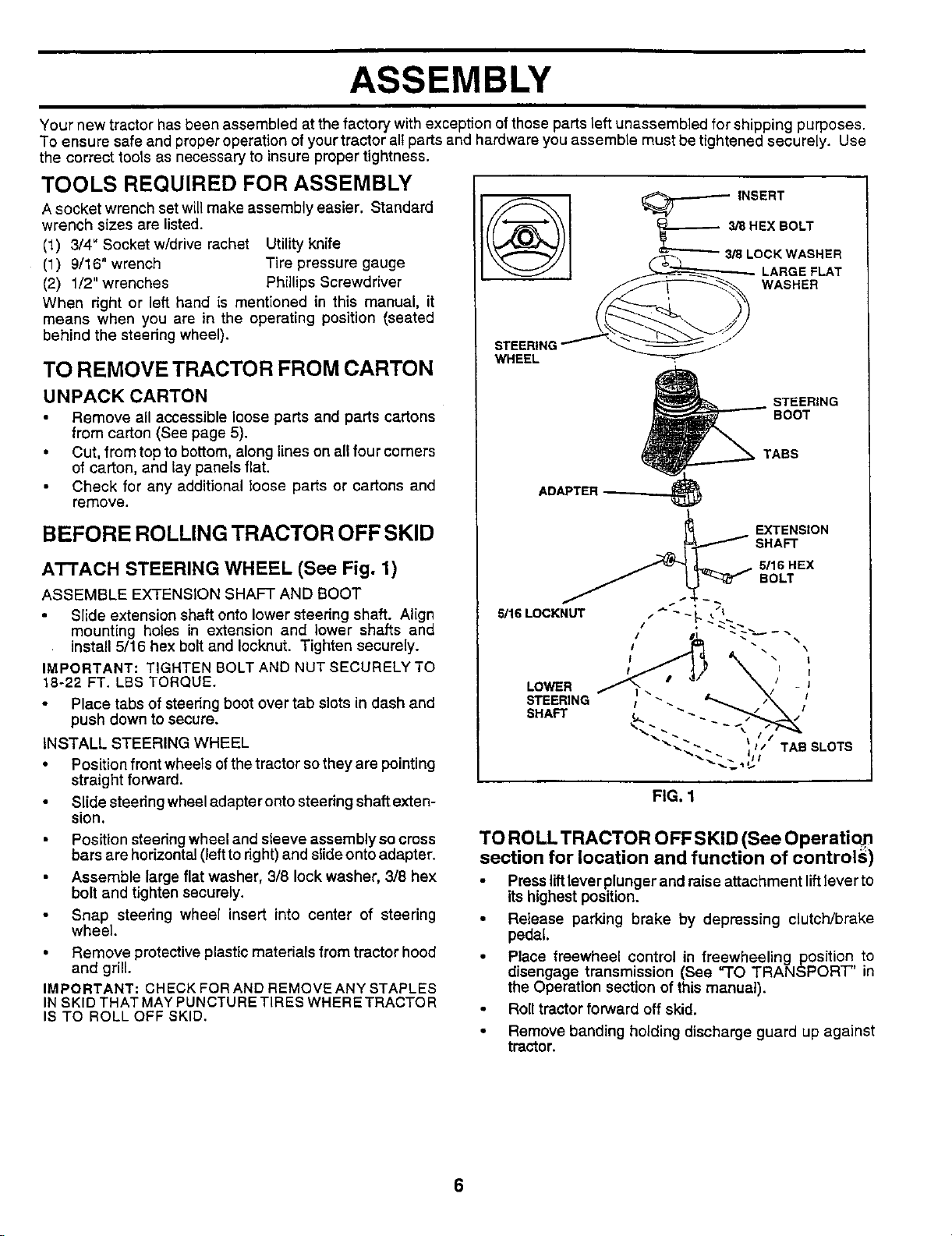
ATTACH STEERING WHEEL (See Fig. 1)
ASSEMBLE EXTENSION SHAFT AND BOOT
Slide extension shaft onto lower steering shaft. Align
mounting holes in extension and lower shafts and
install 5/16 hex bolt and Iocknut. Tighten securely.
IMPORTANT: TIGHTEN BOLT AND NUT SECURELY TO
18-22 FT. LBS TORQUE.
Place tabs of steering boot over tab slots in dash and
push down to secure.
INSTALL STEERING WHEEL
• Position front wheels ofthe tractor so they are pointing
straight forward.
• Slide steedng wheel adapter onto steering shaft exten-
sion.
Position steering wheel and sleeve assembly so cross
bars are horizontal (left to right) and slide onto adapter.
Assemble large flat washer, 3/8 lock washer, 3/8 hex
bolt and tighten securely.
Snap steering wheel insert into center of steering
wheel
• Remove protective plastic materials from tractor hood
and grill.
IMPORTANT: CHECK FOR AND REMOVE ANY STAPLES
IN SKID THAT MAY PUNCTU RE TIRES WHERE TRACTO R
IS TO ROLL OFF SKID.
FIG. 1
TO RO LL TRACTO R O FF S KID (See O perati o_,
section for location and function of controls)
• Pressliftlever plunger and raise attachment liftlever to
its highest position.
• Release parking brake by depressing clutch/brake
pedal.
• Place freewheel control in freewheeling position to
disengage transmission (See "TO TRANSPORT" in
the Operation section of this manual).
Roll tractor forward off skid.
• Remove banding holding discharge guard up against
tractor.
6
ASSEMBLY
HOW TO SET UP YOUR TRACTOR
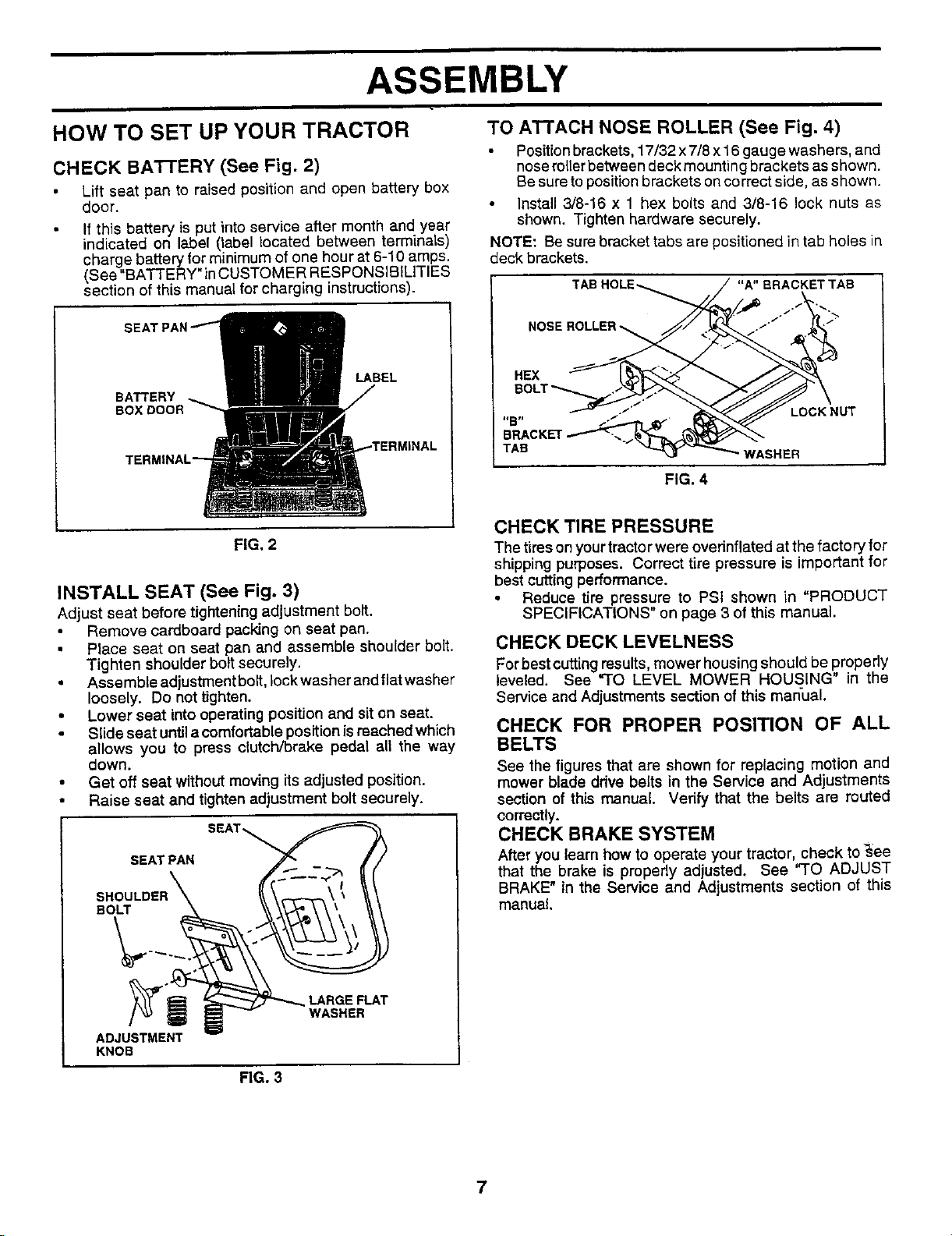
CHECK BA'I-rERY (See Fig. 2)
• Lift seat pan to raised position and open battery box
door.
• f th s battery is put into service after month and year
indicated on label (label located between term na s)
charge battery for minimum of one hour at 6-10 amps.
(See "BATTERY" inCUSTOMER RESPONSIBILITIES
section of this manual for charging instructions).
LABEL
BATTERY
BOX i
FIG, 2
INSTALL SEAT (See Fig. 3)
Adjust seat before tightening adjustment bolt.
Remove cardboard packing on seat pan.
Place seat on seat pan and assemble shoulder bolt.
Tighten shoulder bolt securely.
• Assemble adjustment bolt, lock washer and flat washer
loosely. Do not tighten.
• Lower seat into operating position and sit on seat.
Slide seat until a comfortable position is reached which
allows you to press clutch/brake pedal all the way
down.
• Get off seat without moving its adjusted position.
• Raise seat and tighten adjustment bolt securely.
SEATPAN
BOLT
TO ATTACH NOSE ROLLER (See Fig. 4)
Positionbrackets, 17/32 x7/8 x 16 gauge washers, and
noserollerbetween deck mountin gbrackets as shown.
Be sure topositionbrackets on correct side, as shown.
Install 3/8-16 x 1 hex bolts and 3/8-16 lock nuts as
shown. Tighten hardware securely.
NOTE: Be sure bracket tabs are positioned in tab holes in
deck brackets.
"A" BRACKET TAB
HEX
=_atl
TAB WASHER
LOCK NUT
FIG. 4
CHECK TIRE PRESSURE
The tires on yourtractor were ovednflated at the factory for
shipping purposes. Correct tire pressure is important for
best cutting performance.
Reduce tire pressure to PSI shown in "PRODUCT
SPECIFICATIONS" on page 3 of this manual.
CHECK DECK LEVELNESS
Forbestcuttingresults,mower housingshould be properly
leveled. See "TO LEVEL MOWER HOUSING" in the
Service and Adjustments section of this manual.
CHECK FOR PROPER POSITION OF ALL
BELTS
See the figures that are shown for replacing motion and
mower blade drive belts in the Service and Adjustments
section of this manual. Verify that the belts are routed
correctly.
CHECK BRAKE SYSTEM
After you learn how to operate your tractor, check to _ee
that the brake is properly adjusted. See 'q'O ADJUST
BRAKE" in the Service and Adjustments section of this
manuBL
ADJUSTMENT
KNOB
LARGE FLAT
WASHER
FIG. 3
7
ASSEMBLY
,/"CHECKLIST
BEFORE YOU OPERATE AND ENJOY YOUR NEW
TRACTOR, WE WISH TO ASSURE THAT YOU RECEIVE
THE BEST PERFORMANCE AND SA TISFA CTION FROM
THIS QUALITY PRODUCT.
PLEASE REVIEW THE FOLLOWING CHECKLIST:
,I All assembly instructions have been completed.
,/ No remaining loose parts in carton.
,/ Battery is properly prepared and charged. (Minimum
1 hour at 6 amps).
,/ Seat is adjusted comfortably and tightened securely.
,/ All tires are properly inflated. (For shipping purposes,
the tires were overinflated at the factory).
,/ Be sure mower deck is properly leveled side-to-side/
front-to-rear for best cutting results. (Tires must be
properly inflated for leveling).
J' Check mower and drive belts. Be sure they are routed
properly around pulleys and inside all belt keepers.
,/" Check wiring. See that all connections are still secure
and wires are properly clamped.
•I Before ddving tractor, be sure freewheel control is in
drive position.
WHILE LEARNING HOW TO USE YOUR TRACTOR, PA Y
EXTRA ATTENTION TO THE FOLLOWING IMPORTANT
ITEMS:
,/ Engine oil is at proper level.
,/ Fuel tank is filled with fresh, clean, regular unleaded
gasoline.
,/ Become familiar with all controls - their location and
function. Operate them before you start the engine.
,/ Be sure brake system is in safe operating condition.
,I It is important to purge the transmission before operat-
ing your tractor for the first time. Follow proper starting
and transmission purging instructions (See =TOSTART
ENGINE" and "PURGE TRANSMISSION" in the Op-
eration section of this manual).
8
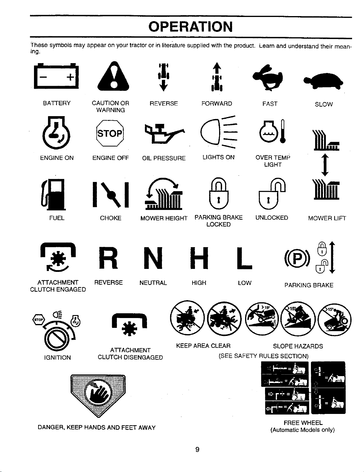
OPERATION
i-hese symbols may appear on your tractor or in literature supplied with the product. Learn and understand their mean-
ing.
BA'Ff'ERY CAUTION OR REVERSE FORWARD FAST SLOW
WARNING
ENGINE ON ENGINE OFF
FUEL CHOKE MOWER HEIGHT PARKING BRAKE UNLOCKED MOWER LIFT
OIL PRESSURE
LIGHTS ON OVLE_TEMP I
LOCKED
R N H L
ATTACHMENT REVERSE NEUTRAL HIGH LOW
CLUTCH ENGAGED
PARKING BRAKE
ATTACHMENT
IGNITION
DANGER, KEEP HANDS AND FEET AWAY
CLUTCH DISENGAGED
KEEP AREA CLEAR SLOPE HAZARDS
(SEE SAFETY RULES SECTION)
FREE WHEEL
(Automatic Models only)
9
OPERATION
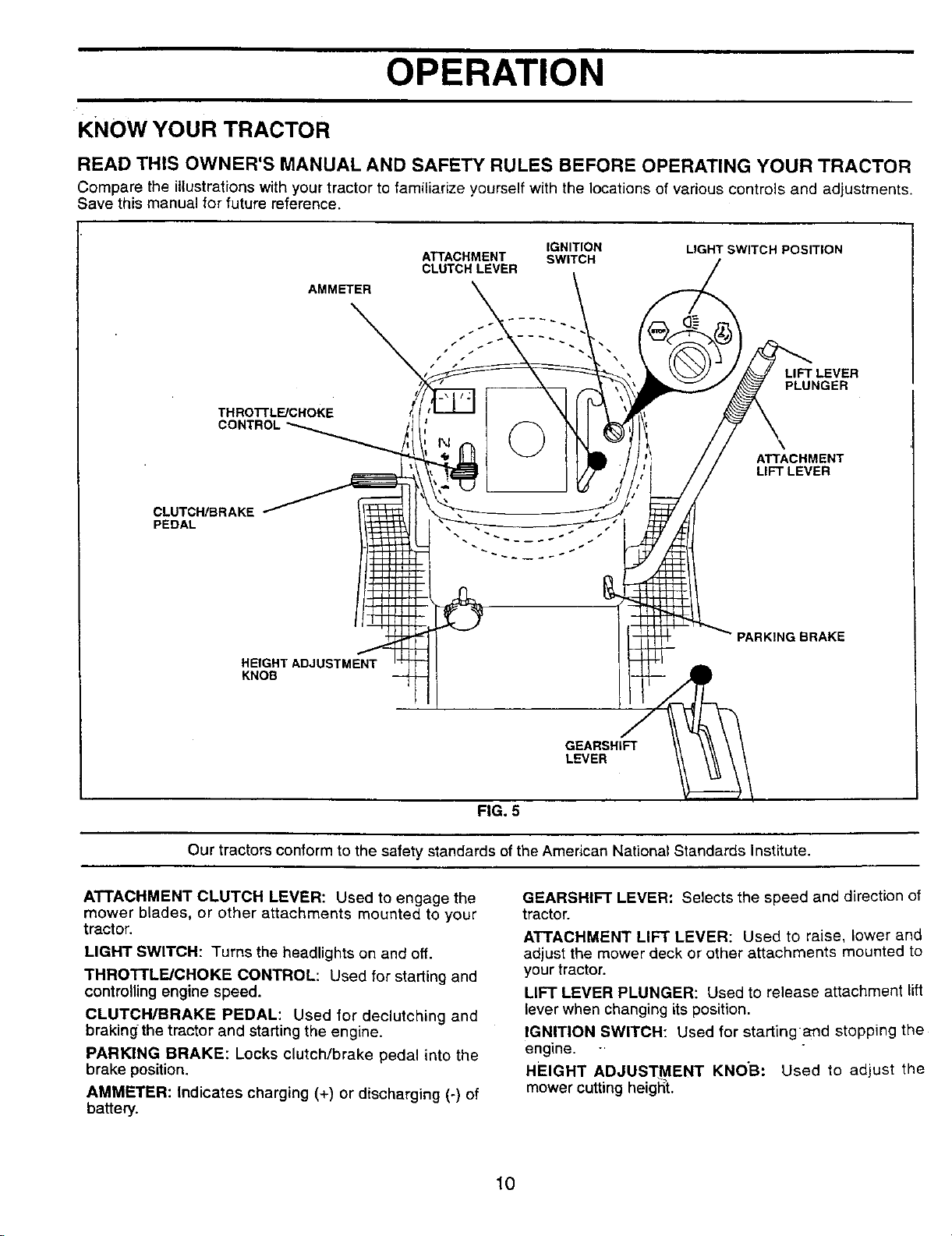
KNOW YOUR TRACTOR
READ THIS OWNER'S MANUAL AND SAFETY RULES BEFORE OPERATING YOUR TRACTOR
Compare the illustrations with your tractor to familiarize yourself with the locations of various controls and adjustments.
Save this manual for future reference.
THROTI'LE/CHOKE
CLUTCH/BRAKE
PEDAL
AMMETER
HEIGHT ADJUSTMENT
KNOB
ATTACHMENT
CLUTCH LEVER
©
IGNITION
SWITCH
LIGHT SWITCH POSITION
LIFT LEVER
PLUNGER
ATTACHMENT
LIFT LEVER
PARKING BRAKE
Our tractors conform to the safety standards of the American National Standards Institute.
ATTACHMENT CLUTCH LEVER: Used to engage the
mower blades, or other attachments mounted to your
tractor.
LIGHT SWITCH: Turns the headlights on and off.
THROTTLE/CHOKE CONTROL: Used for starting and
controlling engine speed.
CLUTCH/BRAKE PEDAL: Used for declutching and
brakingthe tractor and starting the engine.
PARKING BRAKE: Locks clutch/brake pedal into the
brake position.
AMMETER: Indicates charging (+) or discharging (-) of
battery.
GEARSHIFT
LEVER
FIG, 5
GEARSHIFT LEVER: Selects the speed and direction of
tractor.
ATTACHMENT LIFT LEVER: Used to raise, lower and
adjust the mower deck or other attachments mounted to
your tractor.
LIFT LEVER PLUNGER: Used to release attachment lift
lever when changing its position.
IGNITION SWITCH: Used for starting and stopping the
engine.
HEIGHT ADJUSTMENT KNOB: Used to adjust the
mower cutting height.
10
OPERATION
=
The operation of any tractor can result in foreign objects thrown into the eyes, which
can result in severe eye damage. Always wear safety glasses or eye shields while
operating your tractor or performing any adjustments or repairs. We recommend a
wide vision safety mask over spectacles or standard safety glasses.
- i
HOW TO USE YOUR TRACTOR
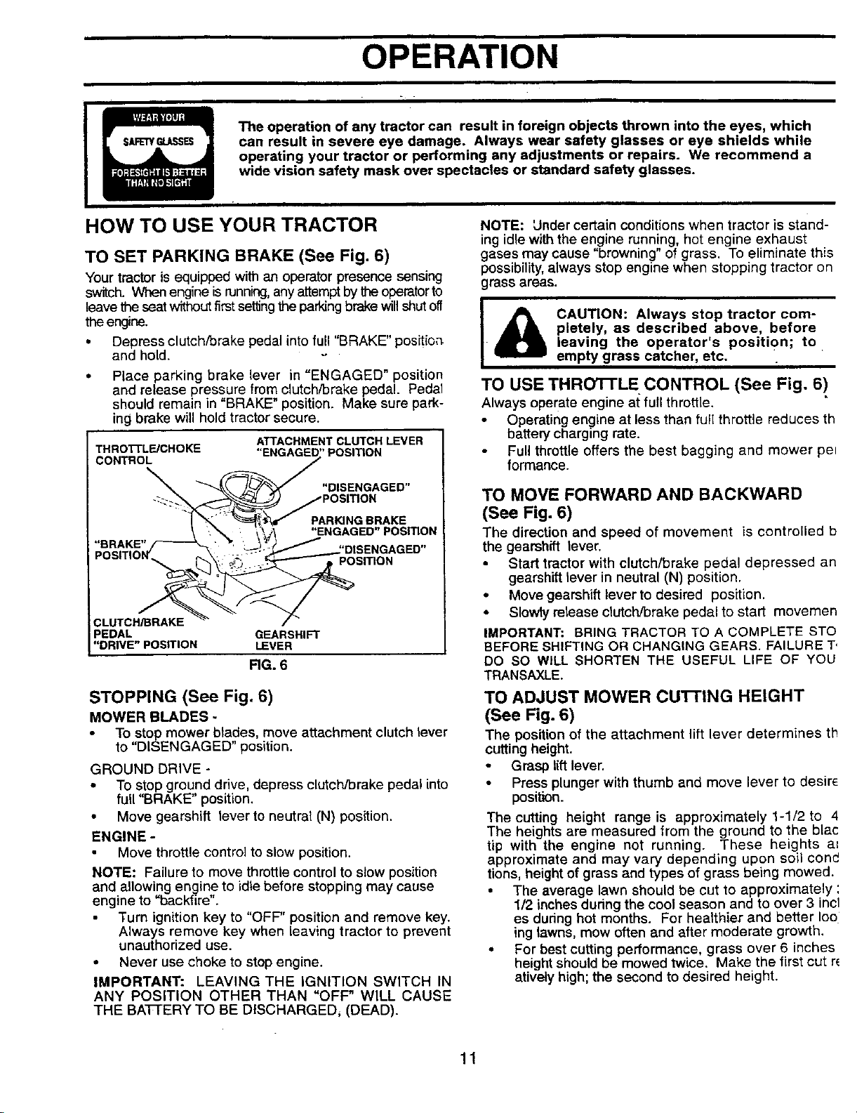
TO SET PARKING BRAKE (See Fig. 6)
Your tractor is equipped with an operator presence sensing
switch. When engine isrunning,anyattempt by the operator to
leave the seat without first setting the pa_ng brake will shut off
the engine.
• Depress clutch/brake pedal into full "BRAKE" positioa
and hold. -o
Place parking brake lever in "ENGAGED" position
and release pressure from clutch/brake pedal. Pedal
should remain in "BRAKE" position. Make sure park-
ing brake will hold tractor secure.
THRO3-1"LF-JCHOKE
CONTROL
CLUTCH/BRAKE
PEDAL GEARSHIFT
"DRIVE"POSITION LEVER
STOPPING (See Fig. 6)
MOWER BLADES
• To stop mower blades, move attachment clutch lever
to "DISENGAGED" position.
GROUND DRIVE -
• To stop ground drive, depress clutch/brake pedal into
full "BRAKE" position.
• Move gearshift lever to neutral (N) position.
ENGINE -
Move throttle control to slow position.
NOTE: Failure to move throttle control to stow position
and allowing engine to idle before stopping may cause
engine to "backfire".
Turn ignition key to "OFF" position and remove key.
Always remove key when leaving tractor to prevent
unauthorized use.
• Never use choke to stop engine.
IMPORTANT: LEAVING THE IGNITION SWITCH IN
ANY POSITION OTHER THAN "OFF" WILL CAUSE
THE BA'I-fERY TO BE DISCHARGEDi (DEAD).
ATTACHMENTCLUTCH LEVER
POSITION
"DISENGAGED"
PARKING BRAKE
"ENGAGED" POSITION
POSITION
RG. 6
NOTE: Under certain conditions when tractor is stand-
ing idle with the engine running, hot engine exhaust
gases may cause "browning" of grass. To eliminate this
possibility, always stop engine when stopping tractor on
grass areas.
pletely, as described above, before
• leaving the operator's position; to
I _ CAUTION: Always stop tractor com-
empty grass catcher, etc.
TO USE THRO3-1"L E CONTROL (See Fig, 6)
Always operate engine at full throttle,
• Operating engine at less than full throttle reduces th
battery charging rate.
Full throttle offers the best bagging and mower pel
formance.
TO MOVE FORWARD AND BACKWARD
(See Fig. 6)
The direction and speed of movement is controlled b
the gearshift lever.
Start tractor with clutch/brake pedal depressed an
gearshift lever in neutral (N) position.
• Move gearshift lever to desired position.
• Slowly release clutch/brake pedal to start movemen
IMPORTANT: BRING TRACTOR TO A COMPLETE STO
BEFORE SHIFTING OR CHANGING GEARS. FAILURE T,
DO SO WILL SHORTEN THE USEFUL LIFE OF YOU
TRANSAXLE.
TO ADJUST MOWER CUI-FING HEIGHT
(See Fig. 6)
The position of the attachment lift lever determines th
cutting height.
Grasp liftlever.
• Press plunger with thumb and move lever to desirs
position.
The cutting height range is approximately 1-1/2to 4
The heights are measured from the ground to the blac
tip with the engine not running. These heights a_
approximate and may vary depending upon soil cone
tions, height of grass and types of grass being mowed.
• The average lawn should be cut to approximately :
1/2 inches during the cool season and to over 3 incl
es during hot months. For healthier and better Io0
ing lawns, mow often and after moderate growth.
• For best cutting performance, grass over 6 inches
height should be mowed twice. Make the first cut re
atively high; the second to desired height.
11
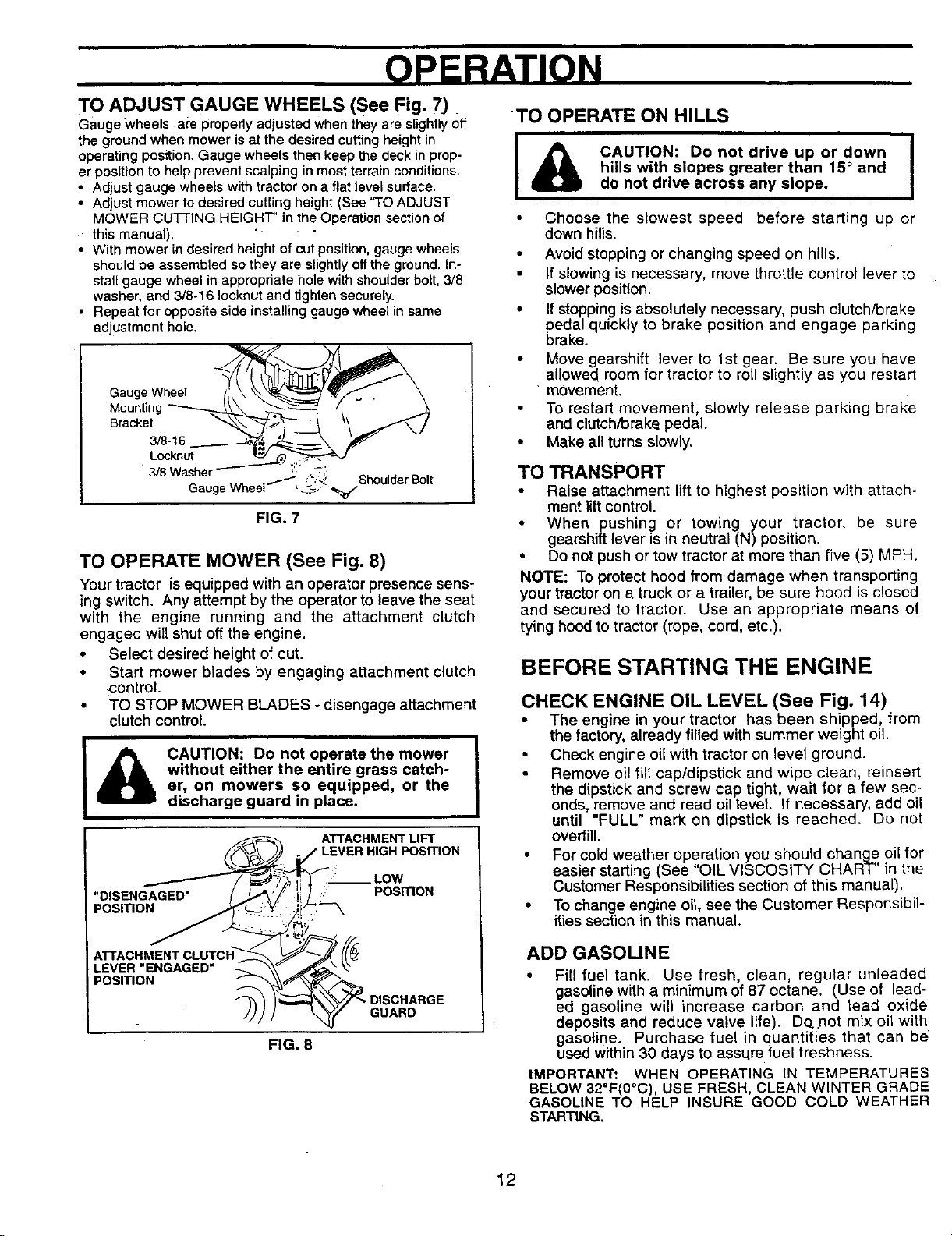
TO ADJUST GAUGE WHEELS (See Fig. 7)
Gauge Wheels are pmpedyadjustedwhentheyare slightlyoff
thegroundwhenmoweris at the desiredcuttingheightin
operatingposition.Gauge wheelsthen keep thedeckinprop-
erpositiontohelppreventscalpinginmostterrainconditions.
• Adjust gauge wheelswith tractor on a flat level surface.
• Adjust mower to desired cutting height (See "TOADJUST
MOWER CUFFING HEIGHT" in the Operation section of
this manual). " "
• With mower in desiredheight of cut position, gauge wheels
should be assembled sothey are slightly off the ground, in-
stal[ gauge wheel in appropriate hole with shoulder bolt, 3/8
washer, and 3/8-16 Iocknut and tightensecurely.
• Repeat for opposite side installing gauge wheelin same
adjustment hole.
Gauge Wheel
Mounting
Bracket
3/8-16
Locknut
3/8 Washer , _.=
Gauge Wheel _:_."
FIG. 7
, .-_ Shoulder Bolt
TO OPERATE MOWER (See Fig. 8)
Your tractor is equipped with an operator presence sens-
ing switch. Any attempt by the operator to leave the seat
with the engine running and the attachment clutch
engaged will shut off the engine.
• Select desired height of cut.
Start mower blades by engaging attachment clutch
control.
TO STOP MOWER BLADES - disengage attachment
clutch control.
CAUTION: Do not operate the mower
without either the entire grass catch-
&
I
er, on mowers so equipped, or the
discharge guard in place.
ATTACHMENTLIFT
__LOW
: POSITION
TO OPERATE ON HILLS
I & CAUTION: Do not drive up or down I
Choose the slowest speed before starting up or
down hills.
• Avoid stopping or changing speed on hills.
• If slowing is necessary, move throttle control lever to
slower position.
• If stopping is absolutely necessary, push clutch/brake
pedal quickly to brake position and engage parking
brake.
Move gearshift lever to 1st gear. Be sure you have
allowed room for tractor to roll slightly as you restart
movement.
• To restart movement, slowly release parking brake
and clutch/brake pedal.
• Make all turns slowly.
hills with slopes greater than 15 ° and
do not drive across any slope.
TO TRANSPORT
• Raise attachment lift to highest position with attach-
ment lift control.
• When pushing or towing your tractor, be sure
gearshift lever is in neutral (N) position.
• Do not push or tow tractor at more than five (5) MPH.
NOTE: To protect hood from damage when transporting
your tractor on a truck or a trailer, be sure hood is closed
and secured to tractor. Use an appropriate means of
tying hood to tractor (rope, cord, etc.).
BEFORE STARTING THE ENGINE
CHECK ENGINE OIL LEVEL (See Fig. 14)
• The engine in your tractor has been shipped, from
the factory, already filled with summer weight oil.
Check engine oil with tractor on level ground.
• Remove oil fill cap/dipstick and wipe clean, reinsert
the dipstick and screw cap tight, wait for a few sec-
onds, remove and read oil level If necessary, add oil
until =FULL" mark on dipstick is reached. Do not
overfill.
• For cold weather operation you should change oil for
easier starting (See "OIL VISCOSITY CHART" in the
Customer Responsibilities section of this manual).
• To change engine oil, see the Customer Responsibil-
ities section in this manual.
FIG. 8
GUARD
ADD GASOLINE
• Fill fuel tank. Use fresh, clean, regular unleaded
gasoline with a minimum of 87 octane. (Use of lead-
ed gasoline will increase carbon and read oxide
deposits and reduce valve life). Dog,not mix oil with
gasoline. Purchase fuel in quantities that can be
used within 30 days to assure fuel freshness.
IMPORTANT: WHEN OPERATING tN TEMPERATURES
BELOW 32°F(0°C), USE FRESH, CLEAN WINTER GRADE
GASOLINE TO HELP INSURE GOOD COLD WEATHER
STARTING.
12
OPERATION
wARNING: Experience indicates that alcohol blended
fuels (called gasohol or using ethanol or methanol) can
attract moisture which leads to separation and formation
of acids during storage. Acidic gas can damage the fuel
system of an engine while in storage. To avoid engine
problems, the fuel system should be emptied before stor-
age o[ 30 days or longer. Drain the gas tank, start the
engine and let it run until the fuel lines and carburetor are
empty. Use fresh fuel next season. See Storage Instruc-
tions for additional information. Never use engine or car-
buretor cleaner products in the fuel tank or permanent
damage may occur.
filler neck. Do not overfill Wipe off
_ CAUTION: Fill to bottom of gas tank
any spilled oil or fuel. Do not store,
spill or use gasoline riear an open
flame.
TO START ENGINE (See Fig. 6)
When starting the engine for the first time or if the engine
has run out of fuel, it will take extra cranking time to move
fuel from the tank to the engine.
• Sit on seat in operating position, depress clutch/brake
pedal and set parking brake.
• Place gear shift lever in neutral (N) position.
Move attachment clutch to "DISENGAGED" position.
• Move throttle control to choke position.
NOTE: Before starting, read the warm and cold starting
procedures below.
Insed key into ignitionand tum key clockwise to "START"
position and release key as soon as engine starts. Do not
runstartercontinuously for more than fifteen seconds per
minute. If the engine does not start after severalattempts,
move throttle control to fast position, wait a few minutes
and try again. If engine stilldoes not start, move the throt-
tle control back to the choke position and retry.
WARM WEATHER STARTING (50 ° F and above)
When engine starts, move the throttle controlto the fast
position.
The attachments and ground drive can nowbe used. If the
engine does not accept the load, restart the engine and
allow it to warm up for one minute using the choke as
described above.
COLD WEATHER STARTING ( 50 ° F and below)
When engine starts, allow engine to run with the throttle
control in the choke position until the engine runs roughly,
then move throttle control to fast position. This may require
an engine warm-up period from several seconds to several
minutes, depending on the temperature.
• The attachments can also be used dudeg the engine warm-
up period.
NOTE: If at a high altitude (above 3000 feet) or in cold
temperatures (below 32 F) the carburetor fuel mixture
may need to be adjusted for best engine performance.
See "TO ADJUST CARBURETOR" in the Service and
Adjustments section of this manual.
MOWING TIPS
Tire chains cannot be used when the mower housin;
isattached to tractor.
Mower should be properly leveled for best mowinc
performance. See "TO LEVEL MOWER HOUSING _
in the Service and Adjustments section of this manu
aL
• Use the runner on the right hand side of mower as
guide. The blade cuts approximately an inch outsid_
the runner (See Fig. 8).
• The left hand side of mower should be used for trim
ming.
• Drive so that clippings are discharged onto the are_
that has been cut. Have the cut area to the right o
the machine. This will result in a more even distribu.
lion of-clippings and more uniform cutting.
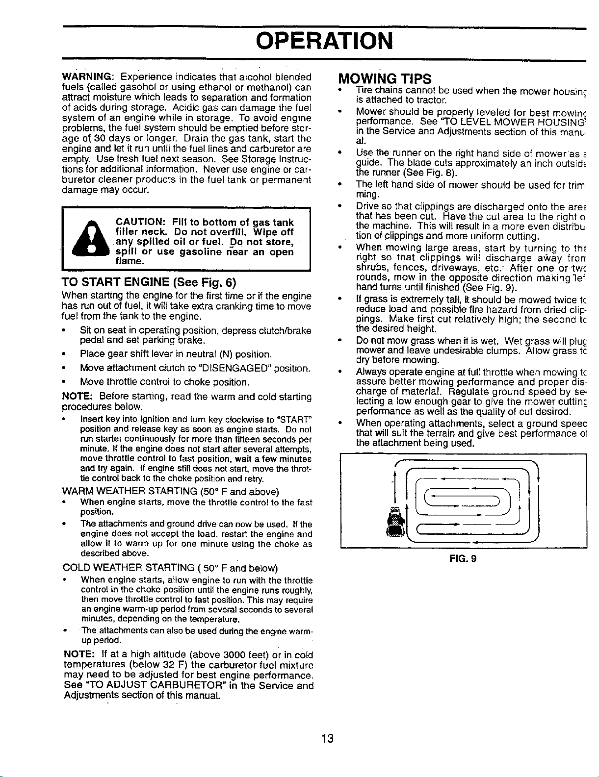
• When mowing large areas, start by turning to th_
right so that clippings wilt discharge aqvay frorr
shrubs, fences, driveways, etc." After one or two
rounds, mow in the opposite direction making 3ef
hand turns until finished (See Fig. 9).
• If grass is extremely tall, it should be mowed twice tc
reduce load and possible fire hazard from dried clip.
pings. Make first cut relatively high; the second tc
the desired height.
Do not mow grass when it iswet. Wet grass will pluc
mower and leave undesirable clumps. Allow grass tc
dry before mowing.
• Always operate engine at full throttle when mowing tc
assure better mowing performance and proper dis.
charge of material. Regulate ground speed by se-
lecting a low enough gear to give the mower cuttin;
performance as well as the quality of cut desired.
When operating attachments, select a ground speec
that will suit the terrain and give best performance ol
the attachment being used.
f
FIG. 9
13
CUSTOMER RESPONSIBILITIES
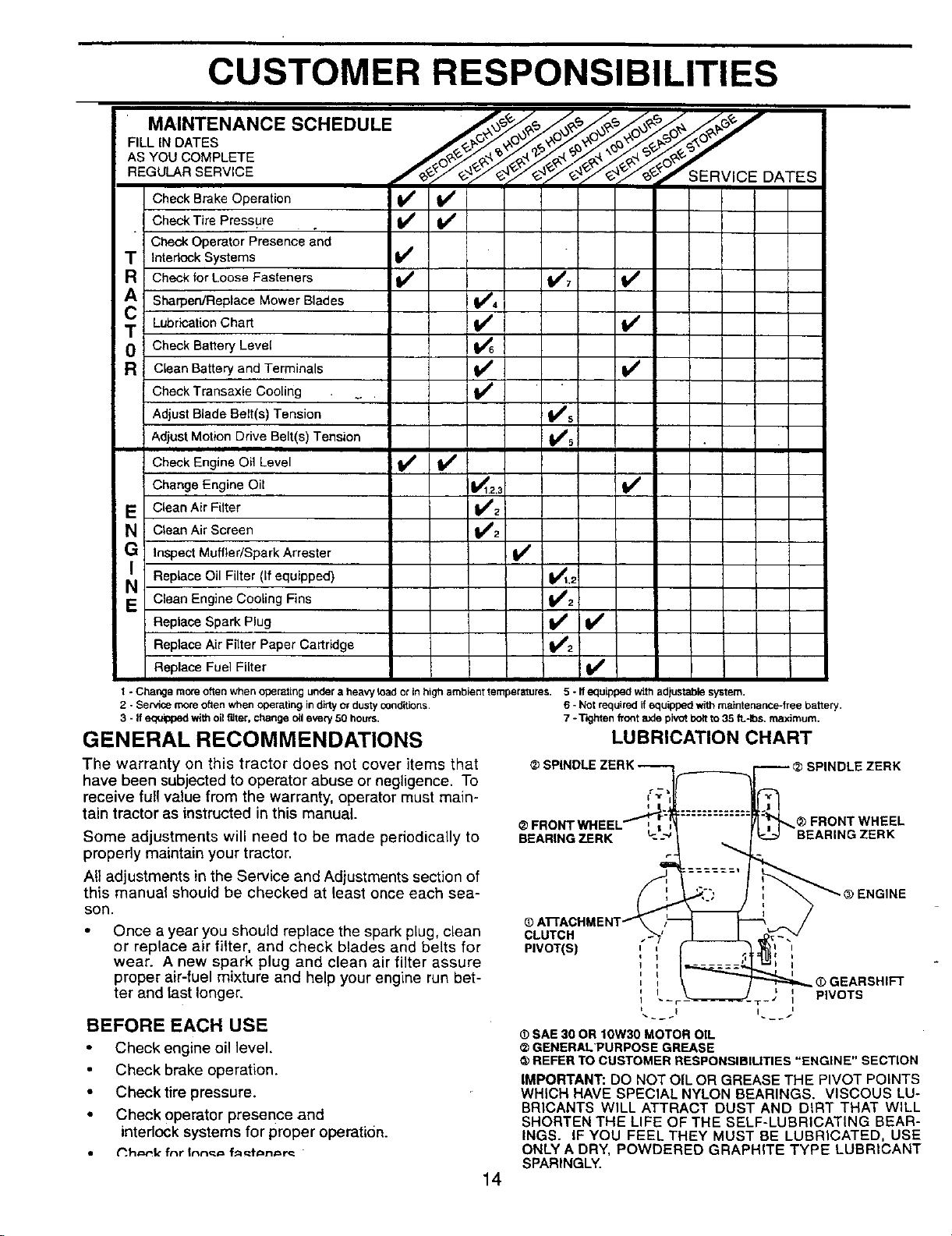
MAINTENANCE SCHEDULE
FILLIN DATES
ASYOUCOMPLETE _.09._.,-_'_-_
REGULARSERVICE
Check Brake Operation {_ _##
CheckTire Pressu[e . i Ik/
CheckOperatorPresenceand
T InterlockSystems _'
R Checkfor LooseFasteners V* VW7 If
A Sharpen/Replace Mower Blades ! V_4
T Lubrication Chart IV* If
0 CheckBatteryLevel i I/6
R CleanBatteryand Terminals IV* V*
CheckTransaxle Cooling _ V*
Adjust Blade Belt(s) Tension V*5
AdjustMotionDriveBelt(s)Tension V_s
Check Engine Oil Level V* If
Change Engine Oil _1.2.3 iI/'
E Clean Air Filter V*2
v*
ERv,oEOA Es
GN! CleanAirscreen V*2
InspectMuffler/SparkArrester if
J,' ReplaceOil Filter(If equipped) V_t.,
E CleanEngineCoolingFins V*2
ReplaceSparkPlug _2 i If
ReplaceAir Filter PaperCartridge
ReplaceFuelFilter If
t - Change more often when operating under a heavy toad ot in high ambient temperatures. 5 - If equipped with adjustable system.
2 - Service more often when Operating in dirtyor dusty conditions.
3 - If equipped with oil f'dter, change oil every 50 hours.
GENERAL RECOMMENDATIONS
The warranty on this tractor does not cover items that
have been subjected to operator abuse or negligence. To
receive full value from the warranty, operator must main-
tain tractor as instructed in this manual.
Some adjustments will need to be made periodically to
properly maintain your tractor.
All adjustments in the Service and Adjustments section of
this manual should be checked at least once each sea-
son.
Once ayear you should replace the spark plug, clean
or replace air filter, and check blades and belts for
wear. A new spark plug and clean air filter assure
proper air-fuel mixture and help your engine run bet-
ter and tast longer.
6 * Not required ff equipped with maintenance-free battery.
7 - TKjhten front &.,de pivot bolt to 35 fL4bs, maximum.
LUBRICATION CHART
CLUTCH
PIVOT(S)
ENGINE
) GEARSHIFT
PIVOTS
BEFORE EACH USE
• Check engine oil level.
Check brake operation.
• Check tire pressure.
• Check operator presence and
interlock systems for proper operation.
• _.h_=rk fnr Inn_€=f_t_n_=rc "
(DSAE 30 OR 10W30 MOTOR OIL
GENERALPURPOSE GREASE
REFER TO CUSTOMER RESPONSIBILITIES "ENGINE" SECTION
IMPORTANT: DO NOT OIL OR GREASE THE PIVOT POINTS
WHICH HAVE SPECIAL NYLON BEARINGS. VISCOUS LU-
BRICANTS WILL ATTRACT DUST AND DiRT THAT WILL
SHORTEN THE LIFE OF THE SELF-LUBRICATING BEAR-
INGS. IF YOU FEEL THEY MUST BE LUBRICATED, USE
ONLY A DRY, POWDERED GRAPHITE TYPE LUBRICANT
SPARINGLY.
14
 Loading...