

Page 1

R
Please do not return unit to retailer.
Por favor, no devuelva el aparato al lugar de compra.
Veuillez ne pas retourner l’outil au détaillant.
1-800-554-6723
www.poulan.com
Instruction Manual
Manual de Instrucciones
ENGLISH
Manuel d’Instructions
810 EPT
WARNING:
Read and follow all Safety Rules and Operating Instructions before using this product. Read instructions carefullybefore assembling. Failure to do so can result in serious injury.
ADVERTENCIA:
Leaelmanualdeinstruccionesysigatodaslasadvertenciase
instrucciones de seguridad. Antes de ensamblar el producto lea
cuidadosamente el instructivo. El no hacerlo puede resultar en lesiones graves.
AVERTISSEMENT:
Veuillez lire le manuel d’instructions et bien respecter tous les
avertissements et toutes les instructions de sécurité. Bien lire les
instructions avant d’assembler l’outil. Tout défaut de le faire pourrait entraîner des blessures graves.
Poulan
1030 Stevens Creek Road
Augusta, GA 30907
Mississauga, Ontario L5V 3E4
5855 Terry Fox Way
Poulan
ESPAÑOL
FRANÇAIS
545117551 8/8/06
Page 2

IDENTIFICATION OF SYMBOLS
Y
DANGER! This unit can be
dangerous! Careless or improper use can cause
serious or even fatal injury.
Always wear appropriate earprotection, eye protection and head protection.
Read and understand the
instruction manual before
using the unit.
DANGER! Falling objects can cause severe head injury. Wear head
protection when operating this unit. Do not stand beneath branch being
cut.
SAFETY RULES
IMPORTANT WARNINGSAND
SAFET
INSTRUCTIONS
WARNING: When using an electric pruner or any other electric garden-
ing appliance, basic safety precautions should always be followed to reduce the risk of fire, electric shock, and serious injury. The warnings and safety instructions in this manual must be followed to reduce the risk of fire, electric shock, or injury, and to provide reasonable safety and
efficiency inusing this unit. The operator is responsible for following the warnings andinstructions
in this manual and on the unit. Read the entire instruction manual before assembling and using
the unit! Restrict the use of this unit to persons who read, understand, and follow the warnings
and instructions in this manual and on the unit. Never allow children to use this unit. Do not allow
the unit to be used as a toy . Close attention is necessary when used near children. Always disconnect unitfrom power source when notin use, before making repairs or adjustments, andwhen
changing accessories and attachments such as bar, chain, or trimmer line. Nonconforming replacement components or the removal of safety devices may cause damage to the unit and possible injury to the operator or bystanders. Use only accessories and replacement parts as recommended. Use only for jobs explained in this manual (or manuals for optional attachments).
WARNING: Because a pruner is a
high-speed wood-cutting tool, special safety
precautions must be observed to reduce the
risk of accidents. Careless or improper use of
this tool can cause serious or even fatal injury.
PLAN AHEAD
S Read this manual carefully until you com-
pletely understand and can follow all safety
rules, precautions, and operating instructions
before attempting to use the unit .
S Restrict the use of your unit to adult users
who understand and can follow safety rules,
precautions, and operating instructions found
on the unit and in this manu al. Never allow
children to operate this unit. Close attention
is necessary when used near children.
INSTRUCTION
MANUAL
S Wear protective gear. Always use steel-toed
safety footwear with non-slip soles; snug-fit ting clothing; heavy, long pants, and long
sleeves; heavy-duty, non-slip gloves; eye
protection such as non-fogging, vented
goggles or face screen; an approved safety
hard hat; and sound barriers (ear plugs or
mufflers) to protect your hearing. Regular users should have hearing checked regularly as
motor noise can damage hearing. Secure hair
above shoulder length. Secure or remove
loose clothing and jewelry or clothing with
loosely hanging ties, straps, tass els, etc.
SAFETY INFORMATION
ON THE UNIT
2
Page 3

Hearing
Protection
Snug
Fitting
Clothing
Safety
Shoes
S Keep children, bystanders, and animals a
minimum of 50 feet (15 meters) away from
the work area. Do not allow other people or
animals to be near when starting or operating the unit. Do not let visitors contact unit or
extension cord.
HAZARD ZONE
S Do not handle or operate this unit when you
are fatigued, ill, or upset, or if you have taken
alcohol, drugs, or medication. You must be in
good physical condition and mentally alert. If
you have any c ondition that might be aggravated by strenuous work, check with doctor
before operating this unit.
S Carefully plan your operation in advance.
Do not start cutting until you have a clear
work area, secure footing, and a planned
retreat path. Cluttered areas invite injuries.
If situations occur which are not covered in
this manual, use care and good judgment. If
you need assistance, contact your authorized
service dealer or call 1-800-554-6723.
Safety Hat
Eye
Protection
Heavy Duty
Gloves
Safety Chaps
50 feet
(15 meters)
DANGER: Do not
use near electrical
wires or power lines.
Keep pruner at least
30 feet (10 meters)
away from all power
lines.
ELECTRICAL SAFETY
(applies to all attachments)
WARNING:
Avoid a dangerous environment. To reduce
the risk of electrical shock, do not use in rain,
in damp or wet locations, or around swimming
pools, hot tubs, etc. Do not expose to snow,
rain, or water to avoid the possibility of electrical shock. Do not use on wet surfaces. Do not
handle extension cord plug or unit with wet
hands. Avoid dangerous situations. Do not
use in the presence of flammable liquids or
gases to avoid creating a fire or explosion
and/or causing damage to unit. Do not abuse
cord. Never carry the unit by the extension
cord or yank extension cord to disconnect
unit. To unplug, grasp the plug, not the cord.
Do not use cord as a handle, close a door on
cord, or pull cord around sharp edges or corners. Turn off all controls before unplugging.
Do not expose cords to heat, oil, or water. Do
not use with damaged cord or plug. If unit is
not working as it should, has been dropped,
damaged, left outdoors, or dropped into water, return it to your authorized service dealer
for repair. Unplug the unit from the power
source when not in use, before servicing, and
when changing accessories and/or attachments. Do not put any object into openings.
Do not use with any opening blocked; keep
free of dust, lint, hairand anything that may reduce air flow.
S Use a voltage supply as shown on unit.
S Avoid dangerous environments. Do not use
in unventilated areas or where dust or explosive vapors can build up.
S To reduce the risk of electrical shock, this
equipment has a polarized plug (one blade
is wider than the other) and will require the
use of a polarized extension cord. The appliance plug will fit into a polarized extension cord only one way. If the plug does not
fit fully into the extension cord, reverse the
plug. If the plug still does not fit, obtain a
correct polarized extension cord. A polarized extension cord will require the use of a
polarized wall outlet. This plug willfit into the
polarized wall outlet only one way. If plug
does not fit fully into the wall outlet, reverse
the plug. If it still does not fit, contac t aqualified electrician to install the proper wall outlet. Do not change the equipment plug, extension cord receptacle, or extension cord
plug in any way.
S To reduce risk of electrical shock, use ex-
tension cords specifically marked as suitable for outdoor appliances having electrical rating not less than the rating of unit.
Cord must be marked with suffix “W--A” (in
Canada “W”). Make sure your extension
cord is in good condition. Inspect extension
cord before use andreplace if damaged. Do
not use a damaged cord. Cord insulation
must be intact with no cracks or deterioration. Plug connectors must be undamaged.
The extension cord used to reach the power source mu st be heavy enough to carry
current from the power source the full length
of the extension cord to the uni t. An undersized extension cord will cause a drop in
line voltage resulting in loss of power and
overheating. If in doubt, use the next heavier gauge. The lower the gauge number, the
heavier thecord (see SELECT AN EXTENSION CORD in the OPERATION section).
S Do not use multiple cords.
S Keep the ex tension cord clear of operator and
obstacles at all times. Position cord so that it
will not be caught on branches.
S Tie cord to cord retainer and connect to re-
cessed plug as shown in this manual to pre-
3
Page 4

vent damage to unit and/or extension cord
and to reduce the possibility of the extension
cord disconnecting from the unit during op-
eration. See ATTACH THE EXTENSION
CORD TO YOUR TRIMMER in the OPERA-
TION section .
S Do not attempt to repair unit. Inspect the insu-
lation and connectors on the powerhead and
extension cord before each use. If there is
any damage, do not use until damage is re-
paired by your authorized service dealer.
S Do not use the unit if the switch does not
turn the unit on and off properly. Repairs to
the switch must be made by your autho-
rized service dealer.
S Avoid unintentional starting ofthe unit. Nev-
er carry unit with your finger on the switch.
Be sure the switch is in the OFF position
and never touch the switch when connect-
ing extension cord.
S Avoid any body contact with any grounded
conductor, such as metal fences, or pipes,
to avoid the possibility of electric shock.
S Ground Fault Circuit Interrupter (GFCI)
protection should be provided on circuit or
outlet to be used. Receptacles are avail-
able having built-in GFCI protection and
may be used for this measure of safety.
S Stop the motor immediately if you are ap-
proached.
DOUBLE INSULATION CONSTRUCTION
This unit is double insulated to help protect
against electric shock. Double insulation
construction consists of two separate “layers”
of electrical insulation instead of grounding.
Tools built with this insulation system are not
intended to be grounded. No grounding
means is provided on this unit, nor should a
means of grounding be added to this unit. As a
result, the extension cord used with your unit
can be plugged into any standard 120 volt
electrical outlet. Safety precautions must be
observed when operating any electrical tool.
The double insulation system only provides
added protection against injury resulting from
an internal electrical insulation failure.
WARNING:
All electrical repairs to this unit, including housing, switch, motor, etc., must be diagnosed and
repaired by qualified service personnel. Replacement parts for a double insulated appliance must be recommended by the manufacturer. A double insulated appliance is marked
with the words “double insulation” or “double insulated”. The symbol (square within a square)
may also be marked on the appliance. Failure to have the unit repaired by qualified service
personnel can cause the double insulation
construction to become ineffective and result in
serious injury.
PRUNER SAFETY
S Do not operate a pruner with one hand. Seri-
ous injury to the operator, helpers, by standers
or any combination of these persons may result from one-handed operation. A pruner is
intended for two-handed use.
S Keep all parts of your body away from the
chain when unit is running.
S Do not operate pruner from a ladder or in a
tree.
S Do not use a pruner to cut down trees or any
portion of the tree trunk.
S Only use for pruning limbs or branches
overhead not greater than 4 inches (10 cm)
in diameter.
S Never stand under the limbyou arepruning.
Always position yourself out of the path of
falling debris.
S Do not cut small brush and saplings with the
pruner. Slender matter may catch in the
chain and be whipped toward you, pulling
you off balance.
S Make sure the chain will not make contact
with any object while starting the unit. Nev er
try to start the unit when the guide bar is in a
cut.
S Do not force pruner. It will do the job better and
safer at the rate for which it was intended.
S Do not putpressure onthe prunerat the end
of the cut. Applying pressure can cause you
to lose control when the cut is completed.
S Do not run the unit at high speed when not
pruning.
S Use the right tool, cut wood only. Don’t use
pruner for purpose not intended; for example,
don’t use pruner for cutting plastic, masonry,
non-wood building materials, etc.
S If you strike or become entangledwith a for-
eign object, stop the unit immediately and
check for damage. Have any damage repaired by an authorized s ervice dealer before attempting further operations.
S Do not operate a pruner that is damaged,
improperly adjusted, or not completely and
securely assembled. Always replace bar
and chain immediately if it becomes damaged, broken or is otherwise removed.
S Always stop the unit when work is delayed or
when walking from one cutting location to
another. Stop the motor and make sure chain
has stopped moving before setting the unit
down.
S Inspect cords periodically and if damaged,
have repaired by an authorized service
dealer.
S Use only in daylight or good artificial light.
KICKBACK
WARNING: Avoid kickback which
can result in serious injury. Kickback is the
backward, upward or sudden forward motion
of the guide bar occurring when the chain
near the upper tip of the guide bar contacts
any object such as a log or branch, or when
the wood c loses in and pinches the chain in
the cut. Contacting a foreign object in the
wood can also result in loss of control.
S Rotational Kickback can occur when the
moving chain contacts an object at the upper
tip of the guide bar. This contact can cause
the chain to dig into the object, which stops
the chain for an instant. The result is a lightning fast, reverse reaction which kicks the
guide bar up and back toward the operator.
4
Page 5
S Pinch-Kickback can occur when the wood
closes in and pinches the moving chain in
the cut alongthe top of the guidebar and the
chain is suddenly stopped. This sudden
stopping of the chain results in a reversal of
the chain force used to cut wood and
causes the pruner to move in the opposite
direction of the chain rotation. The pruner is
driven straight back toward the operator.
S Pull-In can occur when the moving chain
contacts a foreign object in the wood in the cut
along the bottom of the guide bar and the
chain is suddenly stopped. This sudden stopping pulls the pruner forward and away from
the operator and could easily cause the operator to lose control of the pruner.
REDUCE THE CHANCE OF
KICKBACK
S Recognize that kickback can happen. With
a basic understanding of kickback, you can
reduce the element of surprise which contributes to accidents.
S Never let the moving chain contact any ob-
ject at the tip of the guide bar.
S Keep the working area free from obstructions
such as other trees, branches, rocks, stumps,
etc. Eliminate or avoid any obstruction that
your chain could hit while you are cutting.
When cutting a branc h, do not let the guide
bar contact branch or other objects around it.
S Keep your chain sharp and properly ten-
sioned. A loose or dull chain can increase
the chance of kickback occurring. Follow
manufacturer’s chain sharpening and
maintenance instructions. Check tension
at regular intervals, but never with the motor
running. Make sure the bar clamp nut is securely tightened after tensioning the chain.
S Begin and continue cutting at full speed. If
the chain is moving at a slower speed, there
is greater chance of kickback occurring.
S Cut one branch at a time.
S Use extreme caution when re-entering a
previous cut.
S Do not attempt cuts starting with the tip of
the bar (plunge cuts).
S Watch for shifting of wood or other forces that
could close a cut and pinch or fall into chain.
S Use the Reduced- -Kickback Guide Bar and
Low- -Kickback Chain specified for your unit.
MAINTAIN CONTROL
S Keep a good, firm grip on the pruner with
both hands when the unit is running and
don’t let go. A firm grip will help you reduce
kickback and maintaincontrol. Keep the fingers of your left hand encircling and your
left thumb under the assist handle. Keep
your right hand completely around the trigger handle whether your are right handedor
left handed.
S Stand with your weight evenly balanced on
both feet.
S Stand slightly to the left side ofthe pruner to
keep your body from being in a direct line
with the cutting chain.
KICKBACK SAFETY FEATURES
WARNING: The following features
are included on your pruner to help reduce the
hazard of kickback; however, such features
will not totally eliminate this danger. As a
pruner user, do not rely only on safety devices. You must follow all safety precautions,
instructions, and maintenance in this manual
to help avoid kickback and other forces which
can result in serious injury.
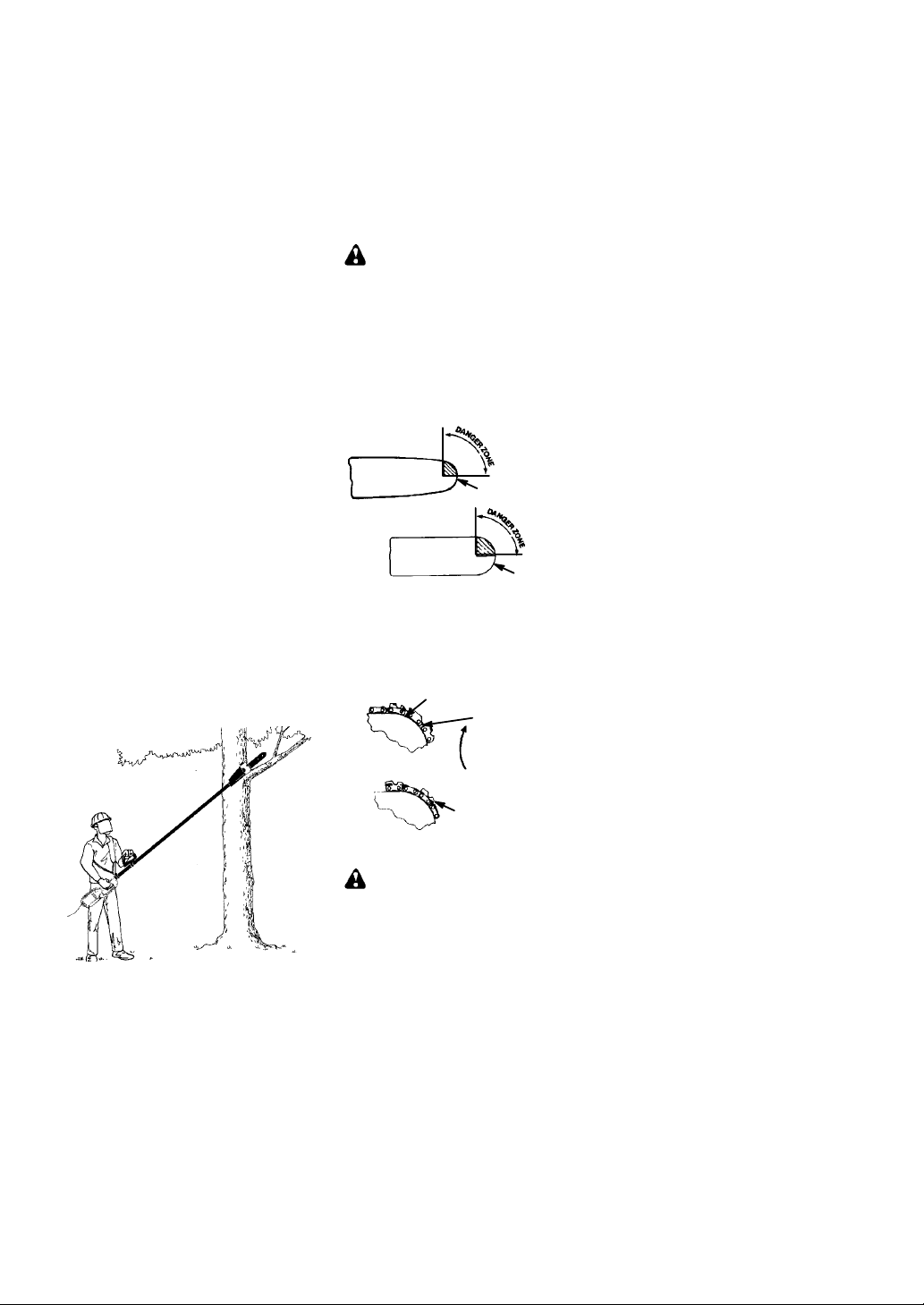
S Reduced--Kickback Guide Bar, designed with
a small radius tip which reduces the size of
the kickback danger zone on the bar tip.
Reduced Kickback Symmetrical Guide Bar
Small Radius Tip
Symmetrical Guide Bar
S Low--Kickback Chain, designed with a con-
toured depth gauge and guard link which
deflect kickback force and allow wood to
gradually ride into the cutter. A low kickback
chain has met kickback performance requirements when tested on the representative
sample of the chain saws specified in ANSI
B175.1.
Low---K ickback
Chain
Contoured Depth Gauge
Large Radius Tip
Elongated Guard Link
Deflects
kickback force
and allows wood
to gradually ride
into cutter
Can Obstruct Mate rial
Not a Low --- Kickback Chain
LINE TRIMMER SAFETY
DANGER: Never use blades with line
trimmer attachment. Never use flailing devices with any attachment. This attachment
(when used with supplied line trimmer attachment) is designed for line trimmer use only.
Use of any other accessories with line trimmer attachment will increase the risk of injury.
5
Page 6

WARNING: Trimmer line throws ob-
jects violently. You and others can beblinded/
injured. Wear safety glasses, boots, and leg
protection. Keep body parts clear of rotating
line.
Eye Protection
Hazard Zone
50 ft.
Boots
Keep children, bystanders, and animals 50
feet (15 meters) away. If approached stop unit
immediately.
WARNING: Inspect the area to be
trimmed before each use. Remove objects
(rocks, broken glass, nails, wire, etc.) which
can be thrown by or become entangled inline.
Hard objects can damage the trimmer head
and be thrown causing serious injury.
S Inspect unit before use. Replace damaged
parts. Make sure all handles, guards, and
fasteners are in place and securely fastened. Parts that are damaged must be repaired or replaced by an authorized service
dealer. These include head parts that are
cracked, or chipped, guards, and any other
part that is damaged.
S Keep firm footing and balance. Do not over-
reach or use from unstable surfaces such as
ladders, trees, steep slopes, rooftops, etc.
S Keep all parts of your body away from cut-
ting head and spinning line.
S Keep thecutting head below waist level. Do
not rais e handles above your waist. Cutting
head can come dangerously close to your
body.
S Use unit properly. Use only for trimming, edg-
ing, scalping, and mowing. Do not force unit.
It will do the job better and with less risk of injury at the rate for which it was designed.
S When using the trimmer attachment, k eep
cutting line at proper length. Use only 0.080″
(2 mm) diameter Poulan brand line. Never
use wire, rope, string, etc.
S Install required shield properly before using
the trimmer attachment. Use only specified
trimmer head and spool; make sure it is
properly installed and securely fastened.
S Cut from your right to your left. Cutting on
left side of the shield will throw debris away
from the operator.
S Store the unit so the line limiter blade (on
underside of shield) cannot cause injury.
S Use only in daylight or in good artificial light.
S Use only for jobs explained in this manual
(or manuals for optional attachments).
(15 meters)
MAINTAIN YOUR UNIT IN GOOD
WORKING ORDER
S Have all service performed by a qualified
service dealer with the exception of the
items listed in the maintenance section of
this manual.
S Maintain unit according to recommended
procedures.
S Make certain the chain and/or cutting head
stops moving when trigger switch is released.
S When using the trimmer attachment,
keep c utting line at proper length. Us e
only 0.080″ (2 mm) diameter Poulan
brand line. Never use wire, rope, string,
etc.
S Install required shield properly before using
the trimmer attachment. Use only specified
trimmer head and spool; make sure it is
properly installed and securely fastened.
S Never modify your unit in any way.
S Keep the handles dry, clean, and free from
oil and grease.
S Keep oil cap, screws, and fasteners se-
curely tightened.
S Keep chain sharp and clean for better and
safer performance.
S Follow instructions for lubricating and chang-
ing accessories and for changing trimmer
line.
S Check for damaged parts. Before further use
of the unit, a part that is damaged should be
carefully check ed to determine that it will operate properly and perform its intended
function. Check for alignment of moving parts,
binding of moving parts, breakage of parts,
mounting and any other conditions that may
affect its operation. Any part that is damaged
should be properly repaired or replaced by an
authorized service dealer unless otherwise
indicated elsewhere in the instruction manual.
S Use only recommended attachments and re-
placement parts to avoid creating a hazard
and/or voiding warranty.
S When not in use, the unit should be stored ina
dry, high or locked-up place out of the reach of
children.
S When storing unit, unplug from the power
source and use a bar sheath when appropriate.
TRANSPORTING AND STORAGE
S Stop the unit and disconnect the power
source when not in use.
S Carry the unit with motor stopped.
S Store unit indoors in a high, dry place out of
the reach of children. Store unit unplugged.
S Do not hang unitso that the trigger switch is
depressed.
SAFETY NOTICE: Exposure to vibrations
through prolonged use of hand tools could
cause blood vessel or nerve damage in the
fingers, hands, and joints of people prone to
circulation disorders or abnormal swellings.
Prolonged use in cold weather has been
linked to blood vessel damage in otherwise
healthy people. If symptoms occur such as
numbness, pain, loss of strength, change in
skin color or texture, or loss of feeling in the
fingers, hands, or joints, discontinue the use
6
Page 7

of this tool and seek medical attention. An
anti--vibration system does not guarantee the
avoidance of these problems. Users who operate power tools on a continual and regular
basis must monitor closely their physical c ondition and the condition of this tool.
RECOMMENDED ATTACHMENTS
This model is equipped with a coupler which
enables optional attachments to be installed.
The optional attachments are:
Edger PP1000E....................
Cultivator PP2000T.................
Blower PP3000B...................
WARNING: Use of any other attach-
ments besides those listed above and the attachment provided with this unit might present a
risk of injury to the operator or bystanders. Only
those attachments listed above and the attachment provided with this unit have been tested for
use with this powerhead.
MODEL:
ADDITIONAL SAFETY RULES
FOR OPTIONAL ATTACHMENTS
WARNING: For each optional attach-
ment used, read entire instruction manualbefore use and follow all warnings and instructions in manual and on attachment.
NOTE: Use the assist handle included with
your unit (as shown below) when operating
the following attachments.
Assist Handle
and discharge tubes free of debris which
can accumulate and restrict proper air flow.
S Never place any object inair intake opening
as this could restrict proper air flow and
cause damage to the unit.
S Never douse or squirt the unit with water or
any other liquid. Cleanunit andlabels with a
damp sponge. Keep handles dry, clean,
and free from oil and grease.
S Never use for spreading chemicals, fertiliz-
ers, or other substances which may contain
toxic materials.
S To avoid spreading fire, do not use near leaf
or brush fires, fireplaces, barbecue pits,
ashtrays, etc.
CULTIVATOR SAFETY
DANGER: RISK OF CUT. KEEP
HANDS AND FEET AW AY FROM TINES AND
CUTTING AREA. Rotating tines can cause serious injury. Do not attempt to clear away cut
material or hold material to be cut when the motor is running. Make sure powerhead is stopped
and disconnected from power source when removing jammed material from the tines. Do not
grab or hold attachment by the tines.
WARNING: Rotating tines can c ause
serious injury. Keep away from rotating tines.
Stop the unit and disconnect the power source
before unclogging tines or making repairs.
BLOWER SAFETY
WARNING: Never put hands or other
objects into blower housing to avoid serious
injury from rotating impeller.
WARNING: Inspect area before
starting unit. Remove all debris and hard objects such as rocks, glass, wire, etc. that can
ricochet, be thrown, or otherwise cause injury
or damage during operation.
S Inspect unit before each use for worn,
loose, missing or damaged parts. Do not
use until unit is in proper working order.
S Do not set unit on any surface except aclean,
hard area. Debris such as gravel, sand, dust,
grass, etc., could be picked up by the air intake and thrown out through discharge opening, damaging unit, property, or causing serious injury to bystanders or operator.
S Never placeobjects inside the blower tubes
or blower outlet. Always direct the blowing
debris away from people, animals, glass,
and solid objects such as trees, automobiles, walls, etc. The force of air can cause
rocks, dirt, or sticks to be thrown or to ricochet which can hurt people or animals,
break glass, or cause other damage.
S Check air intake opening and blower tubes
frequently, always with unit stopped and
power source disconnected. Keep vents
WARNING: Inspect the area to be
cultivated before starting the unit. Remove all
debris and hard and sharp objects such as
rocks, vines, branches, rope, string, etc.
S Hold the unit firmly with both hands
S Keep firmfooting and balance. Do not over-
reach or stand on unstable surfaces.
S Look behind and use care when backing up.
S Keep all parts of your body away from the
tines.
S Never operate the cultivator without the tine
guard in place and properly secured.
S Keep the tines andguard c lear of debris. Al-
ways wear gloves when servicing or cleaning the tines. The tines become very sharp
from use.
S Avoid heavy contact with solid objects that
might stop the tines. If heavy contact occurs, stop the motor and inspect the unit for
damage.
S After striking a foreign object, stop the unit,
disconnect the power source and inspect
the cultivator for damage. Repair before restarting.
S Disconnect attachment from the drive mo-
tor before cleaning the tines with ahose and
water to remove any build--up. Oil the tines
to prevent rust.
S Do not run unit at highspeed unless cultiva-
ting.
7
Page 8

EDGER SAFETY
WARNING: Always use handlebar
when operating edger attachment. Attach
handlebar above arrow on safety label on the
upper shaft (motor end of unit). If your edger
attachment does not include a handlebar, a
handlebar accessory kit (#530071864) is
available from your authorized service dealer.
Instructions for assembling handlebar to your
unit are included in this kit.
Handlebar
DANGER: RISK OF CUT. KEEP
HANDS AND FEET AWAY FROM BLADE
AND CUTTING AREA. Do not attempt to clear
away cut material when the blade is in motion.
Make sure switch is in the off position and the
power source is disconnected when removing
jammed material from the cutting blade. Do not
grab or hold unit by the cutting blade.Ins pec t
the area to be edged before each use. Remove objects (rocks, broken glass, nails,
wire, etc.) which can be thrown by the blade
or can wrap around the shaft.
WARNING: Inspect the area to be
edged before each use. Remove objects
(rocks, broken glass, nails, wire, etc.) which
can be thrown by the blade or can wrap
around the shaft.
S Blade rotates momentarily after the trigger
is released. The blade can seriously cut
you or others.
S Allow blade to stop before removing it from
the cut.
S Hold the unit firmly with both hands.
S Keep firmfooting and balance. Do not over-
reach or stand on unstable surfaces.
S Throw away blades that are bent, warped,
cracked, broken or damaged in any other
way. Replace parts that are cracked,
chipped, or damaged before using the unit.
S Keep all parts of your body away from the
blade.
S Keep blade guard in place and in good
working order.
S Always keep the wheel in contact with the
ground.
S Always push the unit slowly over the
ground. Stay alert for uneven sidewalks,
holes in the terrain, large roots, etc.
S T o reduce the risk of fire, do not allow exces -
sive grass, leaves, or grease to accumulate
on the attachment.
S Objects struck by the cutting member can
cause serious injuries to persons. The lawn
should always be carefully examined and
cleared of all objects prior to edging.
SAVE THESE INSTRUCTIONS
hurt people or animals, break glass, or
WARNING: Use of any other attach-
ments not recommended in this manual may increase the risk of injury to persons, fire, or electrical shock. Use of attachments not covered
under the list of recommended attachments in
this manual have not been evaluated for use
with this powerhead by Underwriters Laboratories (see RECOMMENDED ATTACHMENTS).
WARNING: This unit is not designed
for use with a brushcutter attachment.
VACUUM SAFETY
WARNING: Inspect area before
starting unit. Remove all debris and hard objects such as rocks, glass, wire, etc. that can
ricochet, be thrown, or otherwise cause injury
or damage during operation.
S Never place objects inside the vacuum
tube(s). Always direct the blowing debris
away from people, animals, glass, and solid
objects such as trees, automobiles, walls,
etc.The force of aircan cause rocks, dirt,or
sticks to be thrown or to ricochet which can
cause other damage.
S Never run unit without the proper equip-
ment attached. When using your unit as a
vacuum, always install vacuum tube(s).
S Check air intake opening or vacuum tube(s)
frequently, always with engine stopped and
unit disconnected from power source. Keep
vents and tubes free of debris which can accumulate and restrict proper air flow.
PRUNER SAFETY
(RECIPROCATING BLADE)
WARNING: The reciprocating blade
can cause severe injury. Inspect the unit before use. Do not operate unit with a bent,
cracked or dull blade. Keep away from the
blade.
WARNING: The reciprocating blade is
sharp. Do not touch. To prevent serious injury,
always stop engine and ensure blade has
stopped moving, disconnect unit from power
source, and wear gloves when changing or
handling the blade.
8
Page 9

WARNING: A coasting blade can
l
lowbl
cause injury while it continues to move after the
engine is stopped. Maintain proper control of the
unit until the blade has completely stopped moving. Keep hands, face and feet at a distance
from allmoving parts. Do not attempt to touch or
stop the blade when it is moving.
WARNING: For additional information,
refer to the safety sectio n of the instructio n
manual supplied with your pruner attachment.
HEDGE TRIMMER SAFETY
DANGER: RISK OF CUT; KEEP
HANDS AWAY FROM BLADE -- Blade
moves momentarily after the trigger is released. Do not attempt to clear away cut material when the blade is in motion. Make sure
the unit is disconnected from the power
source and the blade has stopped moving before removing jammed material from the cutting blade. Do not grab or hold the unit by the
cutting blade.
Bladesmove
momentarily
after the
trigger is
released.
WARNING: Inspect the area before
starting the unit. Remove all debris and hard
objects such as rocks, glass, wire, etc. that
can ricochet, be thrown, or otherwise cause
injury or damage during operation.
S Do not us e a cutting blade that is bent,
warped, cracked, broken or damaged in any
other way. Have worn or damaged parts replaced by your authorized service dealer.
S Always keep unit in front of your body.
Keep all parts of your body away from the
cutting blade.
S Keep thecutting bladeand air vents clear of
debris.
A
adestostop
before removing
them from the cut.
SNOW THROWER SAF ETY
WARNING: Keep hands and feet
away from the rotor when starting or running
the unit. Never attempt to clear the rotor with
the motor running. Stop the unit and disconnect from the power source before unclogging snow or debris from discharge chute or
when adjusting vanes.
WARNING: Never lean over dis-
charge c hute. Rocks or debris could be
thrown into the eyes and face and cause serious injury or blindness.
WARNING: Inspect the area where
the unit is to be used. Remove objects that
could be thrown or damage the unit. Some objects may be hidden by fallen snow -- be alert
for the possibility.
S Direct material discharge away from glass
enclosures, automobiles, etc.
S Do not run motor at high speed while not re-
moving snow.
S Be attentive when using the snowthrower,
and stay alert for holes in the terrain and
other hidden hazards.
S Make sure the rotor will spin freely before
attaching the snowthrower to the powerhead.
S If the rotor will not rotate freely due to frozen
ice, thaw the unit thoroughly before attempt ing to operate under power.
S Keep the rotor clear of debris.
S Do not throw snow near other people. The
snow thrower could propel small objects at
high speed causing injury.
S After striking a foreign object, stop the unit,
disconnect from the power source and inspect the snowthrower for damage and repair if necessary before restarting unit.
S Never operate the snowthrower near glass
enclosures, automobiles and trucks.
S Never attempt to use the snowthrower on a
roof.
S Never operate the snowthrower near win-
dow wells, dropoffs, etc.
S Never discharge snow onto public roads or
near moving traffic.
S Clear snow from slopes by going up and
down; never across. Use caution when
changing directions. Never clear snowfrom
steep slopes.
S Let snowthrower run for a few minutes after
clearing snow so moving parts do not
freeze.
S Look behind and use care when backing
up. Exercise caution to avoid slipping or falling, especially when operating in reverse.
S Know how to stop quickly.
9
Page 10

ASSEMBLY
WARNING: If received assembled,
review all assembly steps to ensure your unit
is properly assembled and all fasteners are
secure.
Examine parts for damage. Do not use damaged parts.
NOTE: If you need assistance or find parts
missing or damaged, call 1-800-554-6723.
TOOLS REQUIRED
S Hex wrench
S Chain adjustment tool (bar tool)
INSTALLING PRUNER OR LINE
TRIMMER ATTACHMENT
CAUTION:
tachments, place the unit on a flat surface for
stability.
1. Loosen the coupler by turning the knob
counterclockwise.
2. Remove the shaft cap from attachment (if
present).
3. Position locking/release button of attachment into guide recess of coupler.
4. Push the attachment into the coupler until
the locking/release button snaps into the
primary hole.
5. Before using the unit, tighten the knob securely by turning clockwise.
When removing or installing at-
Coupler
LOOSEN
TIGHTEN
Coupler Primary Hole
Knob
Guide Recess
1. Try on shoulder strap and adjust for fit and
balance before starting the unit or beginning a cutting operation.
2. Insert your right arm andhead throughthe
shoulder strap and allow it to rest on your
left shoulder. Make sure the danger sign
is centered on your back and the hook is
to the right side of your waist.
NOTE: A one-half twist is built in the shoul-
der strap to allow the strap to rest flat on the
shoulder.
3. Adjust the strap, allowing the hook to be
about 3 -- 6 inches (8 -- 15 cm) below the
waist.
4. Fasten the strap hook to the clamp located between the trigger handle and the
assist handle and liftthe toolto the operating position.
NOTE: It may be necessary to relocate the
shoulder strap clamp on the shaft for proper
balancing of unit.
TO RELOCATE SHOULDER STRAP
CLAMP:
1. Loosen and remove both clamp screws.
2. Place the upper shoulder strap clamp
over the upper shaft.
3. Position the lower shoulder strap clamp
under the upper shaft and align the upper
and lower clamp screw holes.
Upper Shoulder
Strap Clamp
POWERHEAD
END
Lower Shoulder
Strap Clamp
ATTACHMENT
END
Screws
Shaft
Locking/
Release
Button
Lower
Attachment
Upper
WARNING: Make sure the locking/
release button is locked in the primary hole
and the knob is securely tightened before operating theunit. All attachments aredesigned
to be used in the primary hole.
For optional attachments, see the ASSEMBLY section of the applicable attachment instruction manual.
SHOULDER STRAP ASSEMBLY
WARNING: Proper shoulder strap
adjustments must be made with the motor
completely stopped before using unit.
4. Insert two screws into the screw holes.
5. Secure shoulder strap clamp by tightening screws with a hex wrench.
ADJUSTING THE ASSIST HANDLE
WARNING: When adjusting the assist
handle during pruner use, be sure it remains between the coupler and the
(closest to coupler) on the safety label to ensure
proper balancing of unit. When adjusting the
assist handle during use of optional attachments (or handlebar for edger attachment), it
must be repositioned between the trigger switch
and the
the safety label.
1. Loosen wing nut on handle.
2. Rotate the handle on the shaft to an up-
upper arrow (closest to motor) on
right position; retighten wing nut.
lower arrow
10
Page 11

ATTACH ING SHIELD
(for line trimmer attachment)
WARNING: Theshieldmustbeprop-
erly installed. The shield provides partial protection from the risk of thrown objects to the operator and others and is equipped with a line limiter
blade which cuts ex cess line to the proper
length. The line limiter blade (on underside of
shield) is sharp and can cut you.
For proper orientation of shield, see KNOW
YOUR TRIMMER A TTACHMENT illustration in
OPERATION section.
1. Remove wing nut from shield.
2. Insert bracket into slot as shown.
3. Pivot shield until bolt passes through hole
in bracket.
4. Securely tighten wing nut onto bolt.
PIVOT
Shield
Line Limiter
Blade
Slot
Bracket
Wing
Nut
OPERATION
KNOW YOUR UNIT
READ THIS INSTRUCTION MANUAL AND SAFETY RULES BEFORE OPERA TING YOUR UNIT .
Compare the illustrations with your unit to familiarize yourself with the location of the various controls
and adjustments . Save this manual for future reference.
Assist Handle
Pruner
Coupler
Bar
Shaft
Chain
Attachment
Hanger
Bar oil fill cap
Bar nut
Line Trimmer
Attachment
Shield
RECESSED PLUG
The RECESSED PLUG is where you attach
your extension cord to the unit.
TRIGGER SWITCH
TheTRIGGERSWITCHisused toturnonthe
unit. Squeeze the trigger switch to operate the
unit. Release to stop.
OPERATING INSTRUCTIONS
Use only a voltage supply as specified on
your unit.
Shoulder Strap Clamp
Motor Housing
Trigger Switch
COUPLER
The COUPLER enables optional attachments to be installed on the unit.
CHAIN TENSION
It is normal for a new chain to stretch during
first 15 minutes of operation. You should
check your chain tension frequently. See
CHAIN TENSION in the SERVICE AND ADJUSTMENTS s ection.
Recessed
Plug
Cord Retainer
SELECT AN EXTENSION CORD
ExtensionCordGaugeChart
Length of Cord Gauge
25 Ft. (7.5 m)
50 Ft. (15 m)
100 Ft. (30 m)
Extension cords are available for this unit.
18 Gauge
16 Gauge
14 Gauge
11
Page 12

ATTACH THE EXTENSION
K
f
L
CORD TO YOUR UNIT
Make a loop in your extension cord andattach
the cord as shown. Ensure the plug and cord
are firmly and fully engaged.
Cord Retainer
1. Loosen the coupler by turning the knob
counterclockwise.
Coupler
Lower
Attachment
Upper Sha
LOOSEN
t
Extension Cord
BEFORE STARTING UNIT
Be sure to read the electrical safety information
in the safety rules section of this manual before
you begin. If you do not understand the electrical
safety information do not attempt to use your
unit. Seek help from someone that does understand the information or call the customer assistance help line at 1-800-554-6723.
GUIDE BAR AND CHAIN OIL
The bar and chain require lubrication. The chain
oiler provides continuous lubrication to the chain
and guide bar. Lack of oil will quickly ruin the bar
and chain. Too little oil will cause overheating
shown by smoke coming from the chain and/or
discoloration of the bar. The oil output is automatically metered during operation. Always fill
the bar oil tank before and during use as needed
(capacity = 4.6 fl. oz.).
Genuine Poulan bar and chain oil is recommended to protect your unit against excessive wear from heat and friction. Poulan oil
resists high temperature thinning.
If Poulan bar and chain oil is not available,
use a good grade SAE 30 oil.
S Never use waste oil for bar and chain lubri-
cation.
S Always stop theunit before removing theoil
cap.
WARNING: Always stop unit and dis-
connect from power source before removing
or installing attachments.
Recessed Plug on Unit
REMOVING PRUNER A TTACHMENT,
LINE TRIMMER ATTACHMENT OR
OTHER OPTIONAL ATTACHMENTS
CAUTION:
tachments, place the unit on a flat surface for
stability.
When removing or installing at-
TIGHTEN
2. Press and hold the locking/release button.
Locking/Release
Button
owerAttachment
3. While securely holding the motor housing
Coupler
and upper shaft, pull the attachment
straight out of the coupler.
nob
Upper Shaft
INSTALLING OPTIONAL ATTACHMENTS
1. Remove the shaft cap from the attachment (if present).
2. Position locking/release button of attachment into guide recess of coupler.
3. Push the attachment into the coupler until
the locking/release button snaps into the
primary hole.
4. Before using the unit, tighten the knob securely by turning clockwise.
Coupler
WARNING: Make sure the locking/
release button is locked in the primary hole
and the knob is securely tightened before operating the unit.
Upper
Shaft
Primary Hole
Locking/
Release
Button
Guide Recess
Attachment
INSTALLING ATTACHMENT
HANGER
An attachment hanger is provided for storage
when attachment is not in use.
To install hanger on attachment:
1. Remove the shaft cap from the attachment (if present) and discard.
2. Press and hold the locking/release button.
3. Push hanger onto the attachment until the
locking/release button snaps into the
hole.
12
Page 13

OPERATING INSTRUCTIONS FOR
PRUNER ATTACHMENT
OPERATING POSITION
ALWAYS WEAR:
Head
Protection
DANGER: Do not extend arms above
shoulders while pruning. Do not stand beneath branch being cut.
WARNING: Always wear head, eye,
hearing, foot and body protection to reduce
the risk of injury when operating this unit.
When operating unit, clip shoulder strap onto
clamp, stand as shown and check for the following:
S Extend your left arm and hold assist handle
with your left hand.
S Hold trigger handle with your right handwith
finger on trigger switch.
S Keep motor end below waist level.
S Keep shoulder strap pad centered on your
left shoulder and danger sign centered on
your back.
S Maintain full weight of tool on your left
shoulder.
Always release the trigger switch as soon as
the cut is completed, allowing the motor to
stop. Keep the cord away from the cutting
area. Position cord so it will not be caught on
branches and the like during cutting.
Eye
Protection
Long Pants
Heavy Shoes
PRUNING
WARNING: Be alert for and guard
against kickback. Do not allow the moving
chain to contact any other branches or objects at the nose of the guide bar when pruning. Allowing such contact can result in serious injury.
IMPORTANT POINTS
S Work slowly, keeping both hands firmly
gripped on the pruner. Maintain secure
footing and balance.
S Plan cut carefully. Check direction branch
will fall.
S Watch out for springpoles. Springpoles are
small size limbs which can catch the chain
and whip toward you or pull you off balance.
Use extreme caution when cutting small
size limbs or slender material.
S Watch out for branches immediately behind
the branch being pruned. If the chain hits
the rear branch, damage to the unit may occur.
S Be alert for springback. Watch out for
branches that are bent or under pressure.
Avoid being struck by the branch or the
pruner when the tension in the wood fibers is released.
S Keep a clear work area. Frequently clear
branches out of the way to avoid tripping
over them.
S Long branches should be removed in
several pieces.
PRUNING TECHNIQUE
When ready to cut, squeeze trigger switch
and allow unit toreach full speed. Apply a light
cutting pressure. DO NOT use back andforth
sawing action.
Second cut
Third cut
Collar
First cut
Pruning technique
1. Make the first cut 6 inches (15 cm) from
the tree trunk on the bottom of the limb.
Use top of guide bar to make this cut. Cut
1/3 through the diameter of the limb.
NOTE: When making the second and third
cuts, rest the foot of the pruner against the
tree limb that is being cut to prevent whipping
of the branch.
Foot
2. Next, move 2 -- 4 inches (5 -- 10 cm) farther out on the limb and make a second
cut all the way through the limb.
3. Then, make a final cut leaving a 1 -- 2inch
(2.5 -- 5 cm) collar from the trunk of the
tree to avoid damage to the tree.
13
Page 14

OPERATING INSTRUCTIONS FOR
TRIMMER ATTACHMENT
OPERATING POSITION
ALWAYS WEAR:
Eye Protection
Long Pants
Heavy Shoes
Cut from your right to your left.
WARNING: Always wear eye protec-
tion. Never lean over the trimmer head.
Rocks or debris can ricochet or be throwninto
eyes and face and cause blindness or other
serious injury.
When operating unit, stand as shown and check
for the following:
S Wear eye protection and heavy clothing.
S Hold trigger handle with right hand and as-
sist handle with left hand.
S Keep unit below waist level.
S Cut from your right toyour left to ensure de-
bris is thrown away from you. Without bending over, keep line near and parallel to the
ground and not crowded into material being
cut.
TRIMMER LINE ADVANCE
The trimmer line will advance approximately 2
inches (5 cm) each time the bottom of the
trimmer headis tapped on the ground with the
engine running at full throttle.
The most efficient line length is the maximum
length allowed by the line limiter.
Always keep the shield in place when the tool
is being operated.
To advance line:
S Operate the engine/motor at full throttle.
S Hold the trimmer head parallel to and above
the grassy area.
S T ap the bottom of the trimmer head lightly on
the ground one time. Approximately 2 inches
(5 cm) of line will be advanced with each tap.
Always tap the trimmer head on a grassy area.
T apping on surfaces such as concrete or asphalt can cause excessive wear to the trimmer
head. If the line is worn down to 2 inches (5 cm)
or less, more than one tap will be required to obtain the most efficient line length.
WARNING: Use only 0.080” (2 mm)
diameter line. Other sizes of line will not advance properly and can cause serious injury.
Do not use other materials such as wire,
string, rope, etc. Wire can break off during
cutting and become a dangerous missile that
can cause serious injury.
CUTTING METHODS
WARNING: Use minimumspeed and
do not crowd the line when cutting around
hard objects (rock, gravel, fence posts, etc.),
which can damage the trimmer head,become
entangled in the line, or be thrown causing a
serious hazard.
S The tip of the line does the cutting. You will
achieve the best performance and minimum line wear by not crowding the line into
the cutting area. The right and wrong ways
are shown below.
Tip of the Line
Does The Cutting
Right
S The line will easily remove grass and
weeds from around walls, fences, treesand
flower beds, but it also can cut the tender
bark of trees or shrubs and scar fences.
S For trimming or scalping, use less than full
throttle to increase line life and decrease head
wear, especially:
S During light duty cutting.
S Near objects around which the line can
wrap such as small posts, trees or fence
wire.
S For mowing or sweeping, use full throttle for
a good clean job.
TRIMMING -- Hold the bottom of the trimmer
head about 3 inches (8 cm) above the ground
and at an angle. Allow only the tip of the line to
make contact. Do not force trimmer line into
work area.
Trimming
3 inches (8 cm)
above ground
SCALPING -- The scalping technique removes unwanted vegetation down to the
ground. Hold the bottom of the trimmer head
about 3 in. (8 cm) above the ground and at an
angle. Allow the tip of the line to strike the
ground around trees, posts, monuments, etc.
This technique increases line wear.
Scalping
MOWING -- Your trimmer is ideal for mowing
in places conventional lawn mowers cannot
reach. In the mowing position, keep the line
parallel to the ground. Avoid pressing the
head into the ground as this can scalp the
ground and damage the tool.
Line Crowded Into
Work Area
Wrong
14
Page 15

Mowing
SWEEPING -- The fanning action of the rotat-
ing line can be used for a quick and easy
clean up. Keep the line parallel to and above
MAINTENANCE
WARNING: Disconnect unit from
power source before performing maintenance.
CHECK FOR LOOSE
FASTENERS AND PARTS
S Bar clamp nut
S Chain
S Bar adjusting screw
S Housing screws
S Assist handle screw
S Debris shield
CHECK FOR DAMAGED OR
WORN PARTS
Contact an authorized service dealer for replacement of damaged or worn parts .
S Trigger switch -- Ensure trigger switch func-
tions properly by pressing and releasing the
trigger switch. Make sure motor starts and
stops.
S Oil tank -- Discontinue use of unit if oil tank
shows signs of damage or leaks.
INSPECT AND CLEAN UNIT AND
LABELS
S After each use, inspect complete unit for
loose or damaged parts. Clean the unit
and labels using a damp cloth.
S Wipe off unit with a clean dry cloth.
CHECK CHAIN TENSION
WARNING: Wear protective gloves
when handling chain. The chain is sharp and
can cut you even when it is not moving. Make
chain adjustments with lower end supported.
Chain tension is very important. Chains
stretch duringuse. This is especially true during the first few times you use your pruner. Always check chain tension each time you use
your unit.
1. Use the screwdriver end of the chain adjustment tool (bar tool) to move chain
around guide bar to ensure kinks do not
exist. The chain should rotate freely.
Chain Adjustment Tool
Guide
Bar
2. Loosen bar clamp nut until it is finger tight
against the bar clamp.
the surfaces being swept and move the tool
from side to side.
Sweeping
Adjusting Screw
3. Turn adjusting screw clockwise until
chain solidly contacts bottom of guide bar
rail. Then, turn adjusting screw an additional 1/4 turn.
Adjusting Screw -- 1/4 Turn
4. Using bar tool, roll chain around guide bar to
ensure all links are in bar groove.
5. Lift up tip of guide bar to check for sag.
Release tip of guide bar, then turn adjusting screw 1/4 turn clockwise. Repeat until
sag does not exist.
6. While lifting tip of guide bar, tighten bar
clamp nut securely with the bar tool.
7. Use the screwdriver end of the bar tool to
move chain around guide bar.
8. If chain does not rotate, it is too tight.
Slightly loosen bar clamp nut and loosen
chain by turning the adjusting screw 1/4
turn counterclockwise. Retighten bar
clamp nut.
9. If chain is too loose, it will sag below the
guide bar and needs to be tightened following above procedure.
WARNING: DO NOT operate the
pruner if the chain is loose. If the pruner is operated with a loose chain, the chain could jump off
the guide bar and result in serious injury.
CHECK CHAIN SHARPNESS
A sharp chain makes wood chips. A dull chain
makes a sawdust powder and cuts slowly.
See CHAIN SHARPENING in the SERVICE
AND ADJUSTMENTS section.
Bar clamp nut
15
Page 16

BAR MAINTENANCE
If your pruner cuts to one side, has to be
forced through the cut, or been run with an improper amount of bar lubrication it may be
necessary to service your bar. A worn bar will
damage your chain and make cutting dif ficult.
After each use, with unit disconnected from
power source, clean all sawdust from the
guide bar and sprocket hole.
To maintain guide bar:
S Disconnect pruner from power source.
S Loosen and remove bar clamp nut and
chain brake. Remove bar and chain from
pruner.
S Clean the oil holes and bar groove after
each 5 hours of operation.
Remove Sawdust From
Guide Bar Groove
S Burring of guide bar rails is a normal
process of rail wear. Remove these burrs
with a flat file.
S When rail top is uneven, use a flat file to re-
store square edges and sides.
Replace guide bar when the groove is worn, the
guide bar is bent or cracked, or when excess
heating or burring of the rails occurs. If replacement is necessary, use only the guide bar specified for your pruner in the repair parts list.
LUBRICATION
File Rail Edges
and Sides
Square
Correct GrooveWorn Groove
Bar Oil
Fill Cap
Oil Holes
SERVICE AND ADJUSTMENTS
WARNING: Disconnect unit from
power source before performing service or
making adjustments.
CHAIN SHARPENING
Chain sharpening is a complicated task that
requires special tools. W e recommended you
refer chainsharpening toa professional chain
sharpener.
CHAIN REPLACEMENT
WARNING: Wear protective gloves
when handling chain. The chain is sharp and
can cut you ev en when it is not moving.
It is normal for a new chain to stretch during the
first 15 minutes of operation. Y ou should recheck your chain tension frequently and adjust
the chain tension as required. See CHAIN TENSION section.
Replace the old chain when it becomes worn or
damaged. Use only the Low-Kickback replacement chain specified in the repair parts list.
TO REPLACE CHAIN:
1. Disconnect pruner from power source.
2. Remove bar clamp nut.
3. Remove bar clamp.
4. Turn adjusting screw by hand counterclockwise until adjusting pin just touches
the stop.
5. Slide guide bar behind sprocket until
guide bar stops against sprocket.
6. Remove the old chain.
7. Carefully remove new chain from package. Hold chain with the drive links as
shown.
S See GUIDE BAR AND CHAIN OIL under
the OPERATION section.
Tip of
Bar
CUTTERS MUST FACE IN
DIRECTION OF ROTATION
Cutters
8. Place chain over sprocket, fitting the drive
links in the sprocket.
9. Fit bottom of drive links between the teeth in
the sprocket in the nose of the guide bar.
10. Fit chain drive links into bar groove.
11. Pull guide bar forward until chain is snug
in guide bar groove. Ensure all drive links
are in the bar groove.
Cutter
Drivelink
Depth Gauge
Drive Links
16
Page 17

12. Now, install bar clamp making sure the
L
adjusting pin is positioned in the lower
hole in the guide bar.
Lower
Hole
Adjusting Pin
4. Insert ends of the lines about 1/2 inch (1
cm) into the small holes on the inside of
spool.
Spool
Small
Holes
Guide Bar
13. Install bar clamp nut and finger tighten
only. Do not tighten any further at this
point. Proceed to the CHAIN ADJUSTMENT section.
CHAIN ADJUSTMENT
See CHECK CHAIN TENSION in MAINTENANCE section.
ine exit holes
REPLACING THE LINE
(for line trimmer attachment)
1. Remove spool by firmly pulling on tap button.
2. Clean entire surface of hub and spool.
3. Replace with a pre-wound spool, or cut two
lengths of
ameter Poulan brand line.
WARNING: Never use wire, rope,
string, etc., which canbreak offand become a
dangerous missile.
12-1/2 feet of 0.080″ (2 mm) di-
5. Wind the line evenly and tightly onto the
spool. Wind in the direction of the arrows
found on the spool.
6. Push the lines into the notches, leaving 3
to 5 inches (7 -- 12 cm) unwound.
7. Insert the lines into the theexit holes in the
hub as shown in the illustration.
8. Align the notches with the line exit holes.
9. Push spool into hub until it snaps into place.
10. Pull the lines extending outside of the hub
to release the lines from the notches.
USER REPLACEABLE SERVICE PARTS
REPLACEMENT PART PART NUMBER
Assist Handle 530057546
Bolt Carriage, 1/4-20 530015786
Wing Nut 530016152
Bar 530044908
Chain 952051549
Hex Nut 530015917
Oil Cap 530053072
Bar Adjusting Screw/Pin Kit 530069110
Handlebar Accessory Kit 530071864
Spool with 0.080″ Trimmer Line 952711616
Shield Assembly 530071964--01
Line in Notch
STORAGE
WARNING: Perform the following
steps after each use.
S Stop the unit and disc onnect the power
source when not in us e.
S Carry the unit with motor stopped.
S Allow motor to cool before storing or trans-
porting.
S Store unit and extension cord indoors in a
high, dry place out of the reach of children.
Store unit unplugged.
S Store unit with all guards in place and position
unit so that any sharp object cannot accidentally cause injury.
SEASONAL STORAGE
Prepare your unit for storage at the end of the
season or if it will not be used for 30 days or
more.
If your unit is to be stored for a period of time:
S Clean it thoroughly before lengthy storage.
S Store in a clean dry area.
S Lightly oil external metal surfaces and guide
bar.
S Oil the chain and wrap it in heavy paper or
cloth.
17
Page 18

TROUBLESHOOTING TABLE
WARNING: Always stop unit and disconnect from the power source before per-
forming all of the recommended remedies below except remedies that require unit tobe
operating.
TROUBLE CAUSE REMEDY
Chain does
not move
when trigger
switch is
engaged.
Chain clatters
or cuts
roughly.
Chain stops
during cut.
Oil inadequate
for bar and
chain lubrication.
Chain cuts at
an angle.
Trimmer head
stops under a
load or does
not turn when
switch is
pressed.
Line does not
advance or
breaks while
cutting.
Line welds
onto spool.
Line releases
continuously.
1. Chain tension incorrect.
2. Guide bar rails pinched.
3. Trigger switch failure.
4. Circuit breaker tripped/
fuse failure.
1. Chain tension incorrect.
2. Cutters damaged.
3. Chain worn.
4. Cutters dull, improperly
sharpened, or depth
gauges too high.
5. Sprocket worn.
1. Chain cutter tops not
filed flat.
2. Guide bar burred or
bent; rails uneven.
1. Oil tank empty.
2. Oil outlet clogged.
3. Guide bar oil hole
blocked.
1. Cutters damaged on
one side.
2. Chain dull on one side.
3. Guide bar bent or worn.
1. Crowding trimmer line
against material being
cut.
2. Electrical failure.
3. Thrown circuit breaker.
4. Debris stopping head.
1. Line improperly routed
in head.
2. Line improperly
wound into spool.
3. Incorrect line size
4. Not enough line
outside of head.
5. Dirt buildup on unit.
1. Line size is incorrect.
2. Incorrect spool.
3. Line is being crowded
against material being cut.
1. Line improperly
routed in head.
2. Spool damaged.
1. See “Check Chain Tension” in
Maintenance section.
2. Repair or replace.
3. Contact an authorized service
dealer.
4. Reset circuit breaker or replace fuse.
1. See “Check Chain Tension” in
Maintenance Section.
2. Contact an authorized service
dealer.
3. Resharpen or replace chain.
4. See “Chain Sharpening” in
Service and Adjustments section.
5. Contact an authorized service
dealer.
1. See “Chain Sharpening” in
Service and Adjustments section.
2. Repair or replace guide bar.
1. Fill oil tank.
2. Contact an authorized service
dealer.
3. Remove bar and clean.
1. See “Chain Sharpening” in
Service and Adjustments section.
2. See “Chain Sharpening” in
Service and Adjustments section.
3. Replace guide bar.
1. Allow tip of line to do the cutting.
2. Contact your authorized service dealer.
3. Check Breaker Box.
4. Remove debris.
1. Check line routing.
2. Rewind line tightly and evenly.
3. Use only 0.080 inch (2 mm) dia. line.
4. Remove cover and pull 4 inches
(10 cm) of line out of head.
5. Clean unit.
1. Use only 0.080 inch (2 mm) dia. line.
2. Replace with correct spool.
3. Cut with tip of line fully extended.
1. Check line routing.
2. Replace spool.
18
Page 19

TROUBLESHOOTING TABLE(continued)
TROUBLE CAUSE REMEDY
Line usage is
excessive.
Line pulls back
into head.
1. Line improperly routed
in head.
2. Line size is incorrect.
3. Crowding line against
material being cut.
4. Spool worn or damaged.
1. Too little line outside
of head.
2. Line size incorrect.
1. Check line routing.
2. Replace spool.
3. Cut with tip of line fully extended.
4. Replace spool.
1. Remove cover and pull 4 inches
(10 cm) of line outside of head.
2. Use only 0.080 inch (2 mm) dia. line.
LIMITED WARRANTY
Poulan warrants to the original purchaser
that each new Poulan brand electric or cordless product is free from defects in material and
workmanship and agrees to repair or replace
under this warranty any defective Poulanbrand
electric product within two (2) years fro m the
original date of purchase.
If your Poulan brand electric or cordless
product should fail within the limited warranty
period, return it, complete, prepaid, with proof
of purchase, to the dealer from whom it was
purchased forrepair or replacement at the option of Poulan.
This warranty is not transferable and does not
cover damage or liability caused by improper
handling, improper maintenance or the use of
accessories and/or attachments not specifically
recommended by Poulan for this electric product. Additionally, this warranty does not cover
parts that will wear and require replacement with
reasonable use during the warranty period. This
warranty does not cover predelivery set--up or
normal adjustments explained in the instruction
manual.
THIS WARRANTY GIVES YOU SPECIFIC
LEGAL RIGHTS, AND YOU MAY HAVE
OTHER RIGHTS WHICH VARY FROM
STATE TO STATE.
NO CLAIMS FOR CONSEQUENTIAL OR
OTHER DAMAGES WILL BE ALLOWED,
AND THERE ARE NO OTHER EXPRESS
WARRANTIES EXCEPT THOSE EXPRESSLY STIPULATED HEREIN.
SOME STATES DO NOT ALLOW LIMITATIONS ON HOW LONG AN IMPLIED WARRANTY LASTS OR THE EXCLUSION OR
LIMI TATI ONS OF INC IDE NTAL OR C O NSEQUENTIAL DAMAGES, SO THE ABOVE
LIMITATIONS OR EXCLUSION MAY NOT
APPLY TO YOU.
The policy of Poulan is to continuously improve its products. Therefore, Poulan reserves the right to change, modify, or dis continue models, designs, specifications, and
accessories of all products at any time without notice or obligation to any purchaser.
19
 Loading...