

Poulan 419757 User Manual
IMPORTANT MANUAL Do Not Throw Away
03076
REPAIR PARTS MANUAL
WARNING:
MODEL:
Read this Man u al and follow all Warnings
and Safety Instructions. Fail ure to do so can
re sult in serious in ju ry.
XT195H42LT
LAWN TRACTOR
ALWAYS WEAR EYE PROTECTION DURING OPERATION
Visit our website: www.poulan-pro.com
419757 Rev. 2 04.28.08 CL Printed in the U.S.A.

HOW TO USE THIS MANUAL
This manual is designed to provide the customer with a means to identify the parts on his/her tractor
when ordering repair parts. The illustrations may or may not represent the actual assemblies; therefore,
it is not recommended to use this manual as a guide to assemble or disassemble the tractor. Some
hardware and parts are drawn larger in order to more readily identify them.
Each tractor has its own model number.
The model number for your tractor can be found on the fender under the seat.
When ordering parts, always give the following information:
• Product - “Tractor”
• MODEL NUMBER - “XT195H42LT (96042007200)”
• Part Number
• Part Description
TABLE OF CONTENTS
SCHEMATIC ................................................................................................................ 3
ELECTRICAL ............................................................................................................ 4-5
CHASSIS ..................................................................................................................6-7
DRIVE........................................................................................................................8-9
ENGINE ................................................................................................................. 10-11
STEERING ................................................................................................................. 12
SEAT .......................................................................................................................... 13
MOWER DECK .....................................................................................................14-15
DECALS .....................................................................................................................16
MOWER LIFT .............................................................................................................17
WARRANTY ...........................................................................................BACK COVER
2
TRACTOR - MODEL NO. XT195H42LT (96042007200), PRODUCT NO. 960 42 00-72
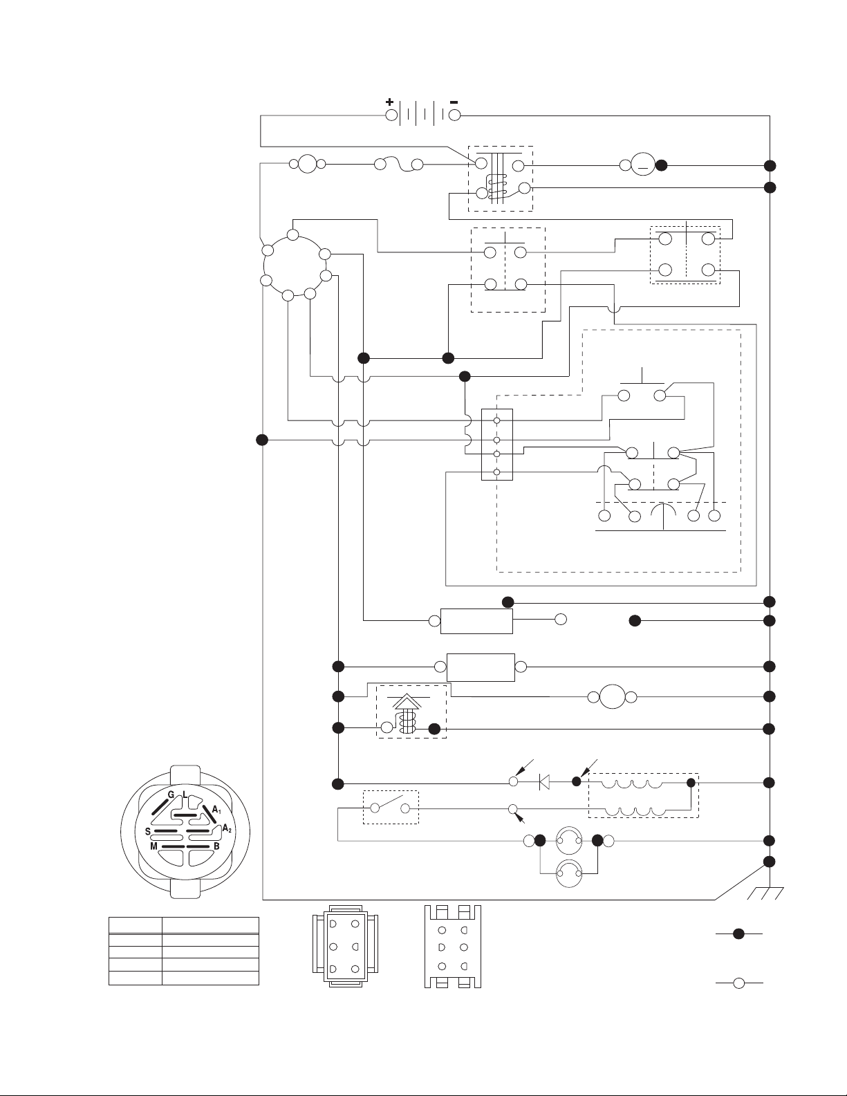
SCHEMATIC
SCH11
RED
(OPTIONAL)
B
G
L
A
AMMETER
S
M
A1
A2
WHITE
FUSE
BATTERY
BLACK
BLACK
BLACK
SOLENOID
DER
CLUTCH/BRAKE
(PEDAL UP)
WHITE
2
3
1
6
JUNCTION
CONNECTOR
BLACK
BLACK
BLACK
BLACKBLACK
GRAY
BLACK
STARTER
M
M
ATTACHMENT CLUTCH
(CLUTCH OFF)
BLACK
GRAY
REVERSE SWITCH
(NOT IN REVERSE)
SEAT SWITCH
(NOT OCCUPIED)
NOTE
YOUR TRACTOR IS
EQUIPPED WITH A SPECIAL
ALTERNATOR SYSTEM.
THE LIGHTS ARE NOT
CONNECTED TO THE
BATTERY, BUT HAVE THEIR
OWN ELECTRICAL SOURCE.
BECAUSE OF THIS, THE
BRIGHTNESS OF THE LIGHTS
WILL CHANGE WITH ENGINE
SPEED. AT IDLE THE LIGHTS
WILL DIM. AS THE ENGINE IS
SPEEDED UP, THE LIGHTS
WILL BECOME THEIR
BRIGHTEST.
IGNITION SWITCH
POSITION
RUN/OVERRIDE
OFF
CIRCUIT
M+G+A1
B+A1
B+A1RUN
B+S+A1START
“MAKE”
L+A2
BLACK
CHASSIS HARNESS
BLUE
63
52
41
CONNECTOR
(MATING SIDE)
BLACK /WHITE
BLUE
FUEL
LINE
FUEL SHUT-OFF
SOLENOID
(IF SO EQUIPPED)
RED
LIGHT SWITCH
DASH HARNESS
CONNECTOR
(MATING SIDE)
CHASSIS
HARNESS
IGNITION
UNIT
(OPTIONAL)
HOUR
METER
CHARGING SYSTEM OUTPUT
3 AMP DC @ 3600 RPM
LIGHTING SYSTEM OUTPUT
5 AMP AC @ 3600 RPM
ORANGE
BROWN
6
3
5
2
4
1
SHORTING
CONNECTOR
SPARK
PLUGS GAP
(2 PLUGS ON
TWIN CYL. ENGINES)
BLACK
12V
POWER OUTLET
(OPTIONAL)
28 VOLTS AC MIN. @ 3600 RPM
(CHARGING SYSTEM DISCONNECTED)
DIODE
14 VOLTS AC MIN. @ 3600 RPM (LIGHTS OFF)
HEADLIGHTS
ALTERNATOR
BLACK
WIRING INSULATED CLIPS
NOTE: IF WIRING INSULATED
CLIPS WERE REMOVED FOR
SERVICING OF UNIT, THEY
SHOULD BE RE-INSTALLED TO
PROPERLY SECURE YOUR
WIRING.
NON-REMOVABLE
CONNECTIONS
REMOVABLE
CONNECTIONS
3
TRACTOR - MODEL NO. XT195H42LT (96042007200), PRODUCT NO. 960 42 00-72
ELECTRICAL
T02S
With 12V Outlet Option
103
59
79
22
21
87
33
30
With Service Minder Option
4646
90
26
16
34
71
40
27
43
42
41
25
28
2
94
29
55
92
93
4

TRACTOR - MODEL NO. XT195H42LT (96042007200), PRODUCT NO. 960 42 00-72
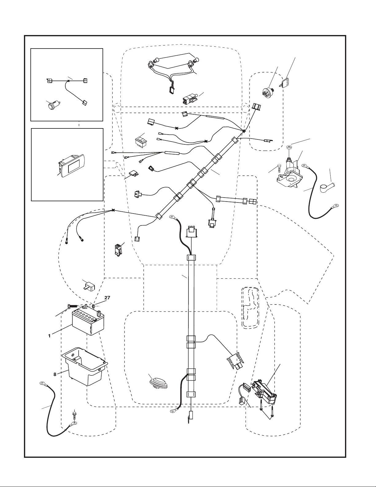
ELECTRICAL
KEY PART
NO. NO. DESCRIPTION
1 163465 Battery
2 74760412 Bolt Hex Hd 1/4-20 unc x 3/4
8 193228 Box Battery
16 176138 Switch Interlock
21 183759 Harness Socket Light
22 4152J Bulb, Light #1156
25 401662 Cable Battery 6 Ga. Red 14.5
26 175158 Fuse
27 73510400 Nut Keps Hex 1/4-20 unc
28 198885 Cable Ground 18" Rear Battery Blk 6 Ga.
29 401545 Switch Seat
30 193350 Switch Ign
33 411935 Key/Chain
34 110712X Switch Light/Reset
40 401098 Harness Ign
41 17720408 Screw 1/4-20 unc x 1/2
42 131563 Cover Terminal Red
43 192507 Solenoid
55 17060512 Screw 5/16-18 x 3/4
71 400449 Harness Ign. Chass.
79 175242 Socket Asm. Bulb Twistlock
87 197802 Switch Interlock Clutch Cable
90 400725 Cover Terminal
92 196615 Harness Pigtail Console ROS
93 192540 Screw Plastic 10-14 x 2.0
94 191834 Modual Reverse ROS
NOTE: All component dimensions given in U.S. inches
1 inch = 25.4 mm
5
TRACTOR - MODEL NO. XT195H42LT (96042007200), PRODUCT NO. 960 42 00-72
CHASSIS
15
176
208
18
207
14
137
5
150
25
186
151
181
196
287
181
37
36
159
162
2
176
182
138
194
194
228
176
177
194
176
235
175
228
236
183
235
130
130
159
152
180
236
197
68
230
159
Chassis-tex_elite-sv pro_9
6

TRACTOR - MODEL NO. XT195H42LT (96042007200), PRODUCT NO. 960 42 00-72
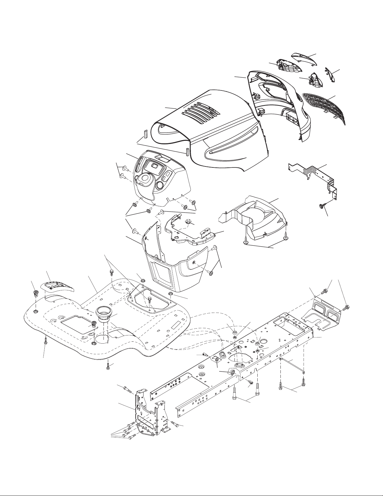
CHASSIS
KEY PART
NO. NO. DESCRIPTION
2 194263 Drawbar
5 197783X428 Dash
14 183393X505 Hood
15 183834X599 Lens Grille LH
18 197482 Grille Asm
25 183835X599 Lens Grille RH
36 17060512 Screw 5/16-18 x 3/4
37 414872X505 Fender
68 17490508 Screw Thdrol 5/16-18 x 1/2
130 416358 Screw #10 x 0.750 ROS Thread
137 184921 Bumper Hood
138 193224X428 Cupholder
150 184322 Duct Heat Hood
151 407807 Bracket Pivot
152 194329 Shield Browning/Debris
159 17000612 Screw Hexwsh Thdrol 3/8-16 x 3/4
162 142432 Screw Hex Wsh Hi-Lo 1/4 x 1/2
175 193243 Crossmember
176 400776 Screw 10-24 x 5/8 Wshd Qdrx
177 195228 Bushing Steering
180 194260 Chassis
181 193102X428 Bushing Mtg. Fender Crgo.
182 193057 Dash Lower
183 74780520 Bolt Fin Hex 5/16-18 x 1-1/4
186 183829X428 Insert Grille
194 73900500 Nut Lock Hex Flange 5/16-18
196 414579 Console Asm. Deck Lift
197 409167 Rod Pivot Chassis
207 183833 Bezel Grille RH
208 183832 Bezel Grille LH
228 195161 Stud Fastener
230 170165 Bolt Shoulder 5/16-18
235 406129 Spacer Fender
236 73930500 Nut center Lock 5/16-18
287 17600406 Screw Hex Washead 1/4-20 x 3/8
NOTE: All component dimensions given in U.S. inches
1 inch = 25.4 mm
7
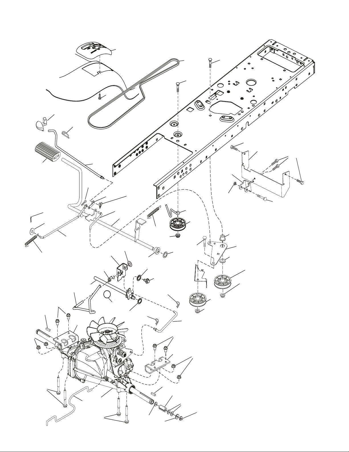
TRACTOR - MODEL NO. XT195H42LT (96042007200), PRODUCT NO. 960 42 00-72
DRIVE
70
42
159
17
2
15
184
125
29
22
221
162
159
175
35
178
74
167
176
23
188
174
64
166
160
165
153
233
161
232
153
51
166
56
171
170
279
231
49
185
125
80
125
121
114
122
186
189
187
50
51
52
51
116
73
99
1
73
205
37
125
162
2
183
205
116
33
drive-tex_T2_fender_5_r1
8

TRACTOR - MODEL NO. XT195H42LT (96042007200), PRODUCT NO. 960 42 00-72
DRIVE
KEY PART
NO. NO. DESCRIPTION
1 418219 Transaxle, Hydro Gear T2
(See Transaxle Breakdown)
2 123583X Key Square
15 19131316 Washer 13/32 x 13/16 x 16 Ga.
17 197296 Spring, Brake
22 197660 Rod Shift
23 130564 Knob Deluxe
29 408391 Rod, Brake
33 12000001 Ring E
35 197722 Rod, Brake, Park
37 121749X Washer 25/32 x 1-1/4 x 16 Ga.
42 8883R Cover, Foot Pedal
49 72110614 Bolt
50 194327 Pulley Idler Flat
51 73900600 Lock Nut 3/8-16
52 194326 Idler V-Groove 910" Offset
56 125907X V-Belt, Drive
64 196200 Shaft Asm. Pedal Brake Control
70 193220X428 Console
73 74490544 Bolt Hex 5/16-18 Gr. 5
74 142432 Screw 1/4 x 1/2
80 408393 Strap Torque
99 408418 Rod Spring Bypass
114 73800500 Nut Lock 5/16-18 unc
116 73900500 Nut Lock Hex Flange 5/16-18
121 175611 Bracket Strap Torque
122 72010520 Bolt 5/16-18 x 2.50
125 17000512 Screw 5/16-18 x 3/4
153 4497H Retainer Spring 1"
159 76020412 Pin Cotter 1/8 x 3/4
KEY PART
NO. NO. DESCRIPTION
160 169484 Retainer Clip
161 105709X Spring, Return, Clutch
162 408784 Adapter Transaxle
165 196212 Bushing
166 197290 Nut Push .625
167 405257 Latch Brake Parking
170 413430 Keeper Belt Centerspan
171 72110622 Bolt
174 197289 Nut Push
175 408539 Shaft Asm Shift
176 196214 Arm Clevis Rod Shift
178 197456 Spring Shift
183 156972 Spacer Axle
184 198403X505 Handle Parking Brake
185 72110620 Bolt
186 194321 Spacer Retainer
187 19133210 Washer
188 194323 Link Clutch Ground Drive
189 194317 Bellcrank Ground Drive
190 194318 Keeper Bellcrank Ground Drive
205 121748X Washer 25/32 x 1-5/8 x 16 Ga.
221 403187 Retainer Spring Clip Handle
231 407287 Idler V-Groove 1.688" Offset
232 74780716 Bolt 7/16-14 x 1 Gr. 5
233 405296 Washer Serrated
279 408538 Link Shift
NOTE: All component dimensions given in U.S. inches
1 inch = 25.4 mm
9
21
20
OPTIONAL EQUIPMENT
Spark Arrester
29
18
15
37
28
engine-bs-1cyl-tex_4
12
42
85
9
90
84
45
1
81
82
69
2
79
97
96
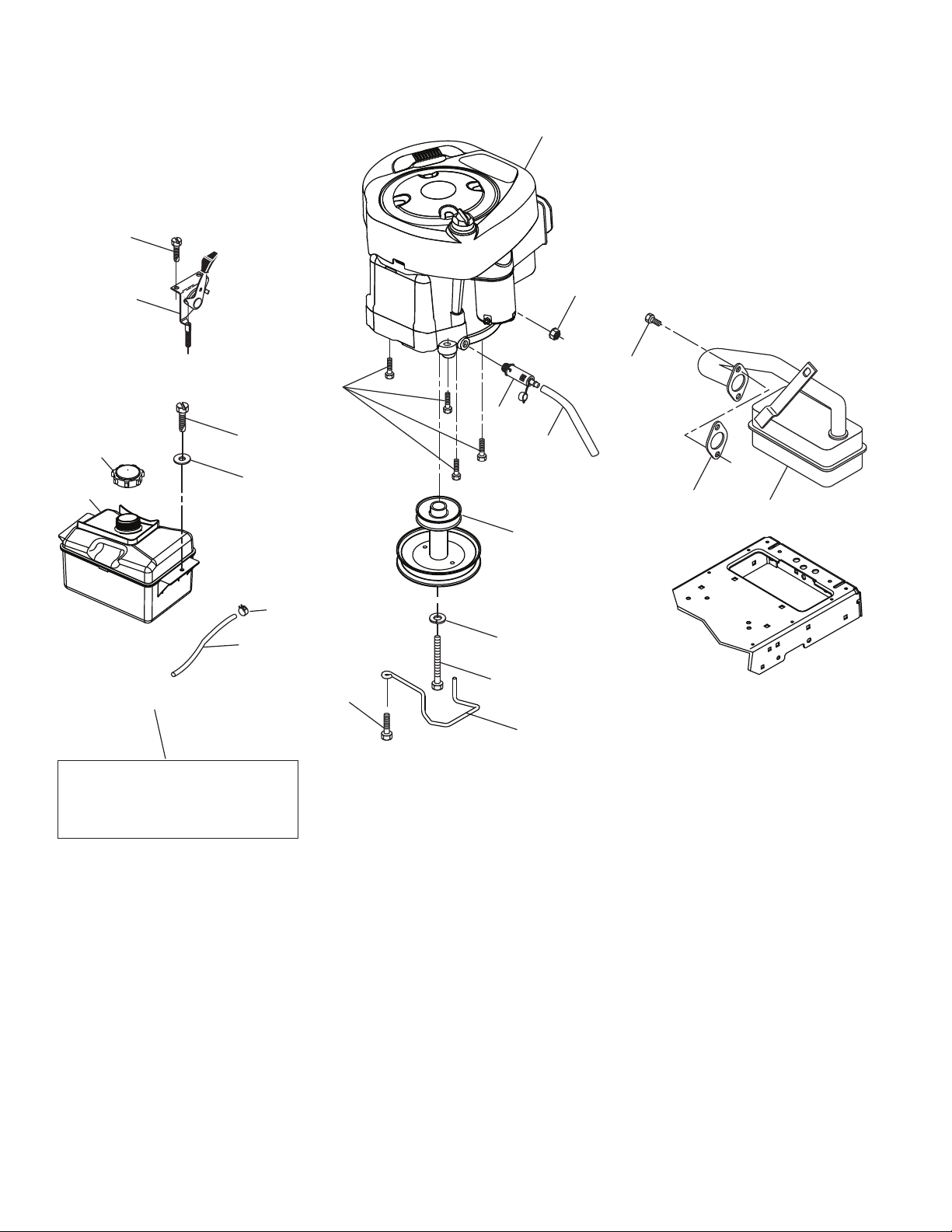
TRACTOR - MODEL NO. XT195H42LT (96042007200), PRODUCT NO. 960 42 00-72
ENGINE
10

TRACTOR - MODEL NO. XT195H42LT (96042007200), PRODUCT NO. 960 42 00-72
ENGINE
KEY PART
NO. NO. DESCRIPTION
1 - - - - - - Engine B&S Model No. 31P677
2 137352 Muffler
9 194319 Keeper Belt Engine
12 401985 Pulley Engine
15 407545 Tank Fuel 1.50
18 197725 Cap Asm
20 176636X428 Control Throttle/Choke
21 416358 Screw #10 x 0.750 BOS Thread
28 401137 Fuel Line
29 137180 Spark Arrester Kit
37 123487X Clamp Hose
42 10040700 Washer Lock 7/16
45 73510400 Nut Keps Hex 1/4-20 unc
69 165291 Gasket
79 192334 Screw Socket Hd 5/16-18 x .75
81 148456 Tube Drain Oil Easy
82 181654 Plug Drain Oil
84 17060620 Screw 3/8-16 x 1-1/4
85 173937 Bolt Hex 7/16-20 x 4 x Gr. 5-1.5
90 17000616 Screw 3/8-16 x 1.0
96 19091416 Washer 9/32 x 7/8 x 16 Ga.
97 17670412 Screw 1/4 - 20 x 3/4
NOTE: All component dimensions given in U.S. inches
1 inch = 25.4 mm
Engine Power Rating Information
The gross power rating for individual gas engine models is labeled in accordance with SAE (Society of Automotive Engineers) code J11940 (Small Engine Power & Torque Rating Procedure), and rating performance has been obtained and
corrected in accordance with SAE J1995 (Revision 2002-5). Actual gross engine power will be lower and is affected by,
among other things, ambient operating conditions and engine-to-engine variability. Given both the wide array of products on which engines are placed and the variety of environmental issues applicable to operating the equipment, the gas
engine will not develop the rated gross power when used in a given piece of power equipment (actual “on-site” or net
horsepower). This difference is due to a variety of factors including, but not limited to, accessories (air cleaner, exhaust,
charging, cooling, carburetor, fuel pump, etc.), application limitations, ambient operating conditions (temperature, humidity, altitude), and engine-to-engine variability. Due to manufacturing and capacity limitations, Briggs & Stratton may substitute an engine of higher rated power for this Series engine.
11
 Loading...