

Page 1
'vJ It/
3400 Counter-Ylbe
CHAINSAW
OPERATOR’S MANUAL
Carefully read and follow
Safety Rules, Precautions
and Operating Instruc
tions. Failure to do so can
result in serious personal
injury.
AwARNING:!
Beaird-Poulan Division
Emerson Electric Co.
Shreveport, Louisiana
Page 2
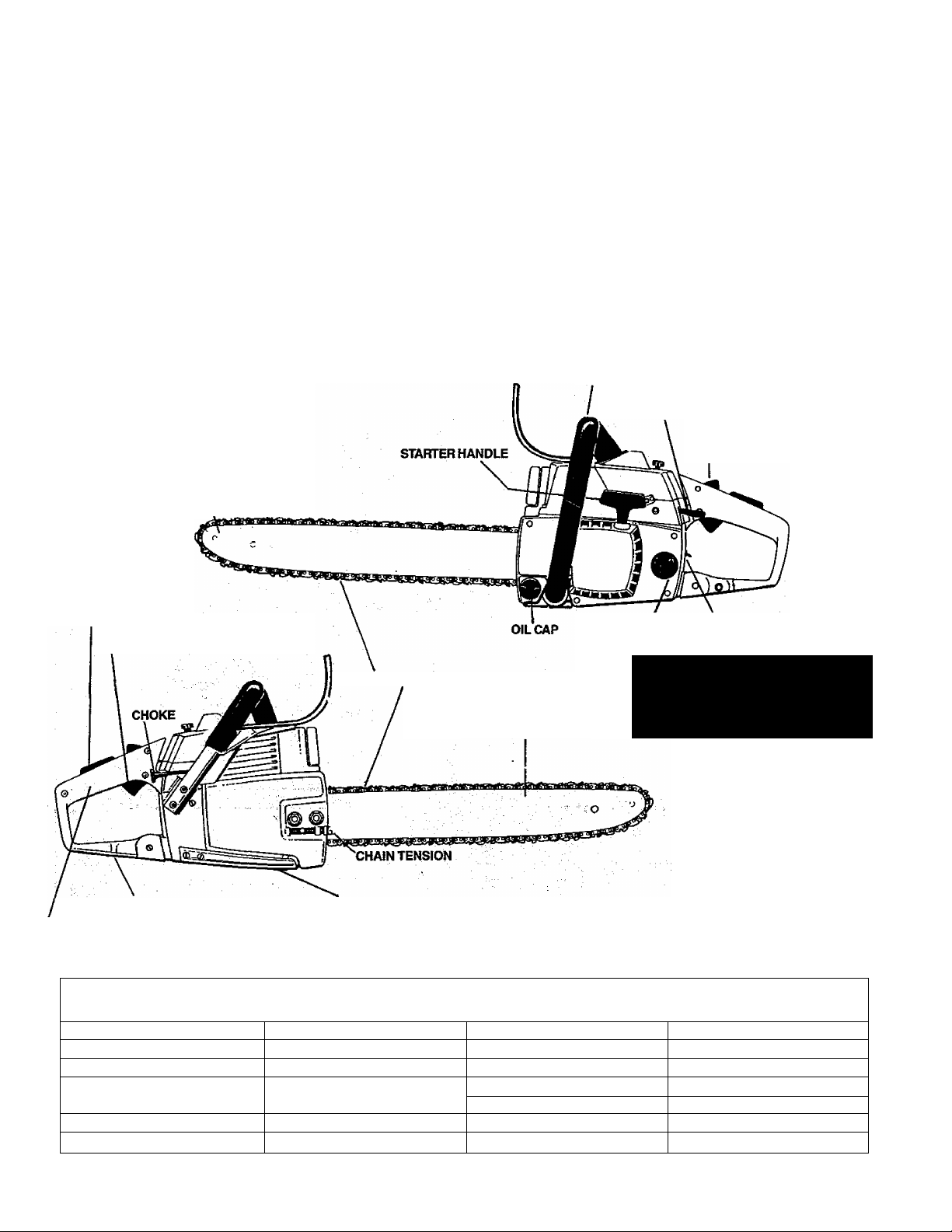
TABLE OF CONTENTS
Specifications ..
SPECIAL SAFETY SECTiON....
Know Your Chain Saw
Preparing Your Saw For Use
A. Getting Ready.......................................................'.____
B. Attaching The Spur
C. Attaching The Bar and Chain
D. Chain Tension....................................................................8
E. Engine Fuel Mixture
F. Bar and Chain Oil
Using Your Saw
A. Control Devices ’.
B. Starting Instructions ......................................................11
Types of Cutting
A. Basic Cutting Technique
REDUCED-KICKBACK GUIDE BAR
...............................................
.................... ЛЛ&5
...
..................................^_ __
...............................................
.................................
...........................................
.........................................................
..........................................................
................................
.....
...................................................... 10
.................................
.................................
:.. ^
...................10
.......................11
................... 7
;.............11
. 2
10
B. Tree Felling Techniques
C. Bucking.....................»....
6
7
7
7
9
D. Debranching and Pruning
Maintenance ........................................................
A. Guide Bar and Chain 16
B. Ignition and Exhaust SystemsC. Starter Rope Repair and Replacement
D. Clutch and Drum/Sprocket
E. Carburetor Adjustments
F. Air Filter .
G. Counter-Vibe® Anti-Vibration System
H. Storage .......................................................................... 21
I. Trouble Shooting Chart
J. Maintenance Chart
...
.....................................................................
.....
......................................... 12
...........
...................................
........................................14
15
......................................
........................
............................................
................................................
.........................
.................................................22
..........................................................
13
17
18.
19
20
21
21
23
Parts List..................................................................24
Parts & Service.................................................... Back Cover
HANDLEBAR
MANUAL OILER
THROTTLE DETENT
THROTTLE LOCKOUT
THROTTLETRIGGER
LOW-KICKBACK CHAIN
REAR CHAIN GUARD
CONTROLHANDLE
FRONT CHAIN CATCHER
■■■ SPlQIFliATIONS "■
MODEL
CU.IN. DISPLACEMENT 3.4cu.in./56 cu.cm.
GUIDE BAR—SPROCKET NOSE 16M 8", 20" Control Tip ^
GUARD LINK CHAIN
SPARK PLUG
SPARK PLUG GAP
3400 Counter Vibe *' IGNITION
3/8 Pitch .050 Gauge
Chrome Cutters - P72S
Champion CJ-8Y
,023 to .027
REDUCED-KICKBACK
GUIDE BAR
MODULE AIR GAP
FUEL MIX
MUFFLER
OILER SYSTEM
FUELTANKCAPACITY
OILTANKCAPACITY
FUEL CAP START-STOP SWITCH
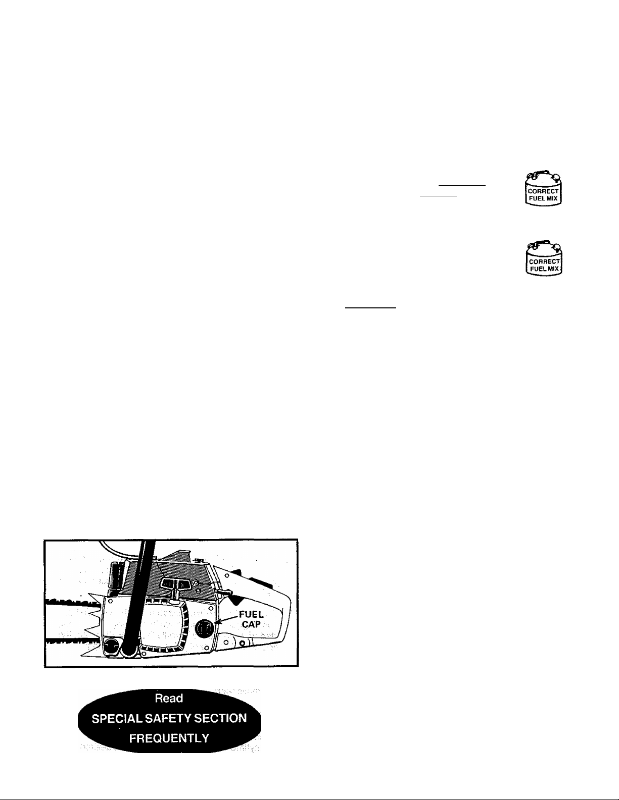
Read
SPECIAL SAFETY SECTION
FREQUENTLY
Solid Stale
.008 to .014
Gasoline/Oii Mixture (see p. 9)
Spark Arresting/Temperature Limiting
Automatic/Manual Override
19 oz. 562 cu.cm.
12oz. 355 cu.cm.
Page 3
SPECIAL SAFETY SECTION
GUARD AGAINST KICKBACK
Kickback is a dangerous reaction that can lead to serious
personal injury. Do not rely only on the sdfety devices
provided with your saw. As a chain saw user, you must
take special safety precautions to help keep your cutting
Jobs free from accident or injury.
! KICKBACK WARNJNG
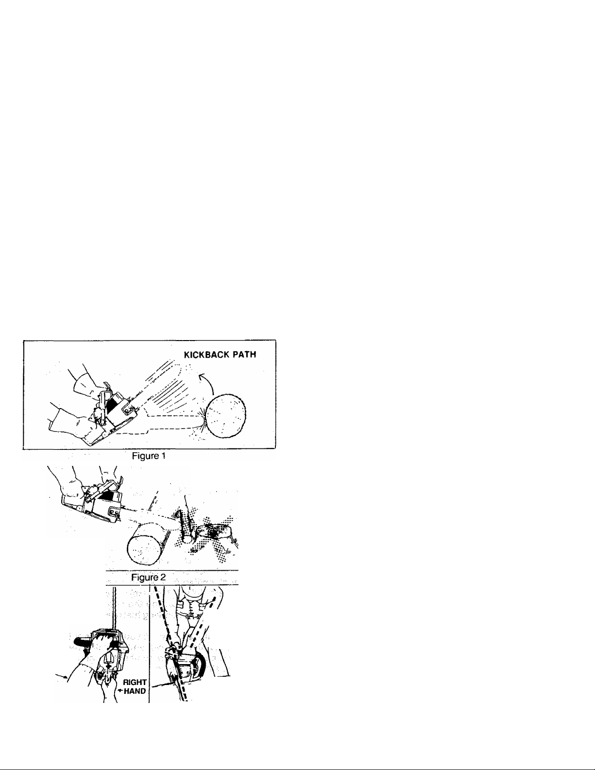
Kickback can occur when the moving chain contacts
an object atthe upper portion of the tip of the guide bar
or when the wood closes in and pinches the saw chain
\nthecui.Contactattheupperportionofthetipofthe
guidebarcan cause the chain to dig into the object and
stop the chain for an instant. The result is aiightning
fast, reverse reaction which kickstheguidebarupand
back toward the operator, if the saw chain is pinched
aiong the top of the guide bar, the guide bar can be
driven rapidiy back toward the operator. Either of
these reactions can cause loss of saw control which
can resuit in serious personai injury.
REDUCE THE CHANCE OF KICKBACK
Recognize that kickback.can happen. With a
1
basic understanding of kickback, you can reduce
the element of surprise which contributes to
accidents.
Never let the moving chain contact any object atthe
2.
tip of the guide bar. Figure 1.
3.
Keep the working area free from obstructions
such as other trees, branches, rocks, fences,
stumps, etc. Figure 2. Eliminate or avoid any
obstruction that your saw chain could hit while you
are cutting through a particular log or branch.
4.
Keep your saw chain sharp and pipperly ten
sioned. Follow manufacturer’s chain sharpening and
maintenance instructions. Check tension at regular
intervals with the engine stopped, never with the engine
running. Make sure the bar clamp nuts are securely
tightened after tensioning the chain. A loose or dull
chain can increase the chance of kickback to occur.
5.
Begin and continue cutting at full throttle. If the
chain Is moving at a slower speed, there is greater
chance for kickback to occur.
6.
Cut one log at a time.
7.
Use extreme caution when re-entering a previous
cut.
8.
Do not attempt plunge cuts.
9.
Watch for shifting logs dr other forces that could
close a cut and pinch or fall into the chain.
10.
Use the Reduced-Kickback Guide Bar and LowKickback Chain specified for your saw.
CLEAR
WORKING AREA
NEVER
REVERSE
HAND
POSITIONS
LEFT HAND
Figure 3
AVOID
OBSTRUCTIONS
STAND
TO THE
f* / LEFT OF
V A THE SAW
ELBOW
LOCKED
THUMB ON
UNDER SIDE
OF HANDLEBAR
MAINTAIN CONTROL
Keep a good firm grip on the saw with both hands
1
when the engine is running and don’t let go.
Figure 3. A firm grip can neutralize kickback and
help you maintain control of the .saw. Keep the
fingers of your left hand encircling and your left
thumb under the front handlebar. Keep your right
hand completely around the rear handle whefher
you are right handed or left handed. Keep your left
arm straight with the elbow locked.
is in a straight line with your right hand on the rear
handle when making bucking cuts. Figures. Never
reverse right and left hand positions for any typei of
cutting.
3.
stand with your weight evenly balanced on
both feet.
4.
Stand slightly to the left side of thè saw, to keep
your body from being in a direct line with the
cutting chain. Figures.
5.
Do not overreach. You could be drawn or thrown
off balance and lose control of the saw.
6.
Do not cut above shoulder height. It is difficult to
maintain control of the saw above shoulder height.
Page 4
SPECIAL SAFETY SECTION (continued)
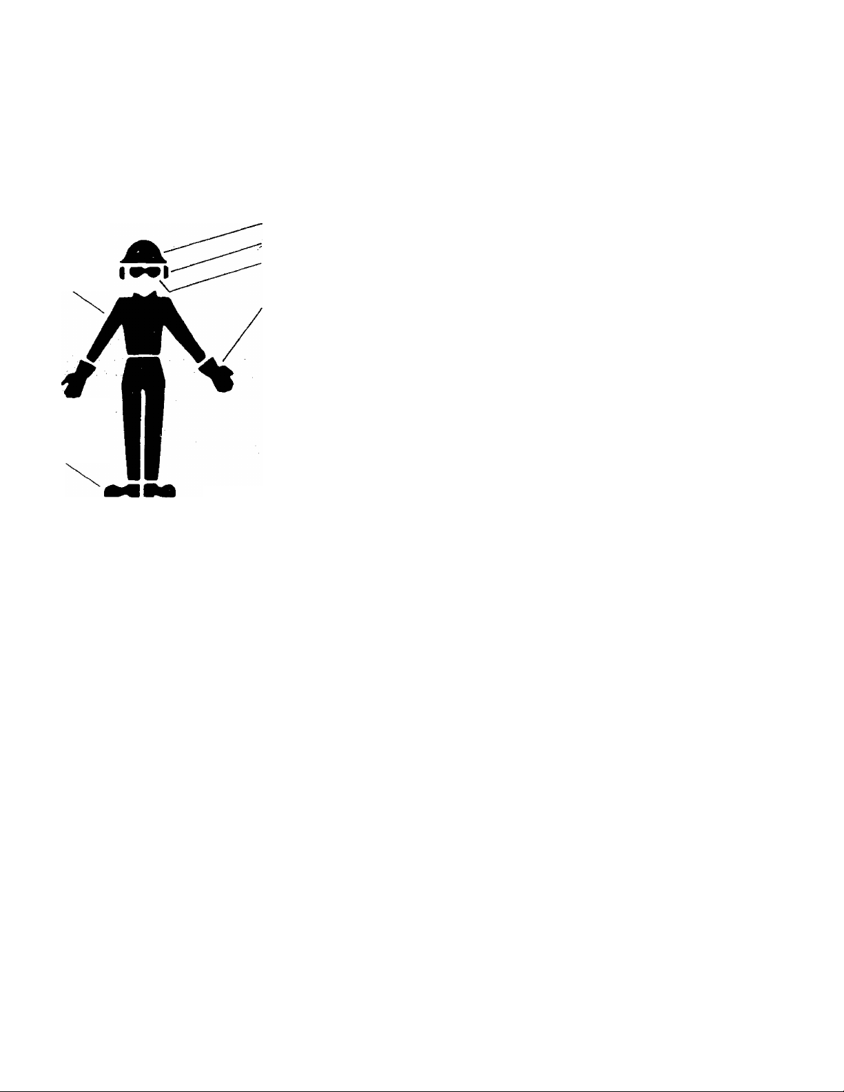
I. WARNING
Because a chain saw is a high-speed wood-cutting tooi, special safety precautions must
be observed to reduce the risK of personal accidents. Careless or improper use can
cause serious personal injury.
SAFETY HAT
SNUG
FITTING
CLOTHING
SAFETY
SHOES
HEARING PROTECTION
EYE PROTECTION
HEAVY DUTY GLOVES
Figure 4
KNOW YOUR SAW
1. Read your Operator’s Manual carefully until you com
pletely understand and can follow ail safety rules and
operating instructions before attempting to operate the
unit.
2. Restrict the use of your saw to adult users who under
stand and follow the safety rules, precautions, and
operating Instructions found In this manual.
PLAN AHEAD
1. Wear personal protective gear. Figure 4. Always use
steel-toed safety footwear with non-slip soles; snug-fitting
clothing: heavy-duty non-slip gloves; eye protection such
, non-fogging, vented goggles or face screen; an ap^ proved safety hard hat, and sound boners—ear plugs or
mufflers to protect your hearing. Regular users should
have hearing checked regularly as chain saw noise can
damage hearing.
2. Keep children, bystanders, and animals out of the
work area—a minimum of 30 feet (10 meters). Do not
allow othejr people or animals to be near the chain saw
when starting or operating the chain saw.
3. Do not handle or operate a chain saw when you are
fatigued, ill, or upset; or if you have taken alcohol,
drugs or medication. You must be in good physical
condition and mentally alert. Chain saw work is
strenuous. If you have any condition that might be
aggravated by strenuous work, check with your doctor
before operating a chain saw.
4.
Do not attempt to use your chain saw during bad
weather conditions such as strong wind, rain, snow,
etc., or at night.
5.
Plan yoursawing operation carefully in advance. Do
not start cutting until you have a clear work area, secure
footing, and if you are felling trees, a planned retreat path.
AVOID REACTIVE FORCES
Pinch-Kickback and Pull-in occur when the chain is
suddenly stopped by being pinched, caught, or by
contacting a foreign object in the wood. This results in a
reversal of the chain force used to cut wood and causes the saw
to move in the opposite direction of chain rotation. Pinch-
Kickback drives the saw straight back toward the operator.
Pufl-ln pulls the saw away from the operator. Either reactions
can result in loss of control and possible serious person^ Injury.
To avoid Pinch-Kickback:
1. Be extremely aware of situations or obstructions
that can cause material to pinch the top of or other
wise stop the chain.
2. Do not cut more than one log at a time.
3. Do not twist the saw as the bar is withdrawn from an
under-cut when bucking.
To avoid Pull-in:
1. Always begin cutting with the engine at full throttle
and the saw frame or spur against the wood.
2. Use wedges made of plastic or wood, (never of metal)
. to hold the cut open.
HANDLE FUEL WITH CAUTION
1.
Eliminate all sources of sparks or flame in the areas
where fuel is mixed, poured, or stored. There should
be no smoking, open flames, or work that could cause
sparks.
Mix and pour fuel in an outdoor area, on bare ground;
2.
store fuel in a cool, dry, well-ventilated place; and use
an approved, marked container for ail fuel purposes.
3.
Wipe up all spilled fuel before starting your saw.
4.
Move at least 10 feet (3 meters) away from fuel and
fueling site before starting the engine.
5.
Do not smol№ while handling fuel or while operating
the saw.
6.
Turn the engine off and let your saw cool before
removing the fuel tank cap and refueling the unit.
7.
Let the saw cool in a non-combustible area, not on
dry leaves, straw, paper; etc.
Page 5

OPERATE YOUR SAW SAFELY
1. Do not operate a chain saw that is damaged, im
properly adjusted, or not completely and securely
assembled.
2. Operate the chain saw only in outdoor areas.
3. Do not operate the saw from a ladder or in a tree.
4. Position all parts of your body to the left of cut and
away from the saw chain when the engine is
running.
5. Cut wood only. Do not use your saw to pry or shove
away limbs, roots or other objects.
6. Make sure the chain will not make contact with any ob
ject while starting the engine. Never try to start the saw
when the guide bar is in a cut or kerf.
7. Use extreme caution when cutting small size briish
and saplings. Slender material can catch the saw
chain and be whipped toward you or pu!| you off
balance.
8. Be alert for springback when cutting a limb that is
under tension so you will not be struck by the limb or
saw when the tension in the wood fibers Is released.
9. Do not put pressure on the saw at the end of a cut.
This can cause you to lose control when the cut is
completed.
10. Stop the engine before setting the saw down.
MAINTAIN YOUR SAW IN GOOD WORKING ORDER
1. Have all chain saw service performed by a qualified
service dealer with the exception of the items listed
in the maintenance section of this manual. For
example, if improper tools are used to remove or hold
the flywheel when servicing the clutch, structural
damage to the flywheel can occur and cause the
flywheel to burst.
2. Keep fuel and oil caps, screws and fasteners
securely tightened.
3. Keep the handles dry, clean, and free of oil or fuel
mixture.
4. Make certain the saw chain stops moving when the
throttle trigger is released. For correction, refer to
page 20 fo> carburetor idle adjustment instructions.
5. Stop the saw if the chain strikes a foreign object. In
spect the unit and repair or replace parts as necessary.
6. Disconnect the spark plug before performing any
maintenance except for carburetor adjustments.
7. Never modify your saw in any way. Use only attach
ments supplied or specifically recommended by the
manufacturer.
8. Always replace the handguard immediately if it
becomes damaged, or broken or is otherwise
removed.
CARRY AND STORE YOUR SAW SAFELY
1. Hand carry the unit with the^engine stopped, the
Muffler away from your body, and the Guide Bar and.
Chain to the rear covered preferably with a scabbard.
2. Before transporting in any vehicle or storing in any
enclosure, allow your saw to cool completely, cover
the bar and chain and properly secure to avoid
turnover, fuel spillage or damage.
3. Drain oil and fuel tank before storing for more than
30 days.
4. Store in a dry area out of the reach of children and
away from where fuel vapors can reach sparks or an
open flame from hot water heaters, furnaces, etc.
NOTE: Exposure to vibrations through prolonged use of
chain saws may produce Whitefinger disease
(Raynaud’s phenomenon). This phenomenon
reduces the hand’s ability to feel and regulate
temperature, produces numbness and burning
sensations and can cause nerve and circulation
damage and tissue necrosis.
An anti-vibration system designed to reduce
engine vibration is recommended for those using
chain saws on a regular or sustained basis. An antivibration system does not guarantee the
avoidance of Whitefinger disease. Continual and
regular users must monitor closely their use of
chain saws and physical condition.
Notice: Refer to the Code of Federal Regulations, Section
1910.266(5); 2.5.1 of American National Standard
Safety Requirements for Puipwood Logging, ANSI
03.1-1978; and relevant state safety codes when
using a chain saw for logging purposes.
SAVE THESE INSTRUCTIONS
Page 6
KNOW YOUR CHAIN SAW
A. INTRODUCTION ^
• Your saw has been designed with safety in mjnd and
includes the following features as standard equipment:
-Reduced-Kickback Guide Bar (Contfol Tip®)
— Low-Kickback Chain (ElongatedGuard Link)
— Spark Arrestor
—Temperature Limiting Muffler
— Handguards
—Temperature Limiting Mufflei'
-Counter-Vibe® Anti-Vibration System
A WARNING
The following features are included on your saw to help
reduce the hazard of kickback, however, such features
will not totally eliminate this dangerous reaction. As a
chain saw user, do not rely only on safety devices. You
must follow all safety precautions, Instructions and
maintenance in this manual to help avoid kickback and
other forces which can result in serious personal injury.
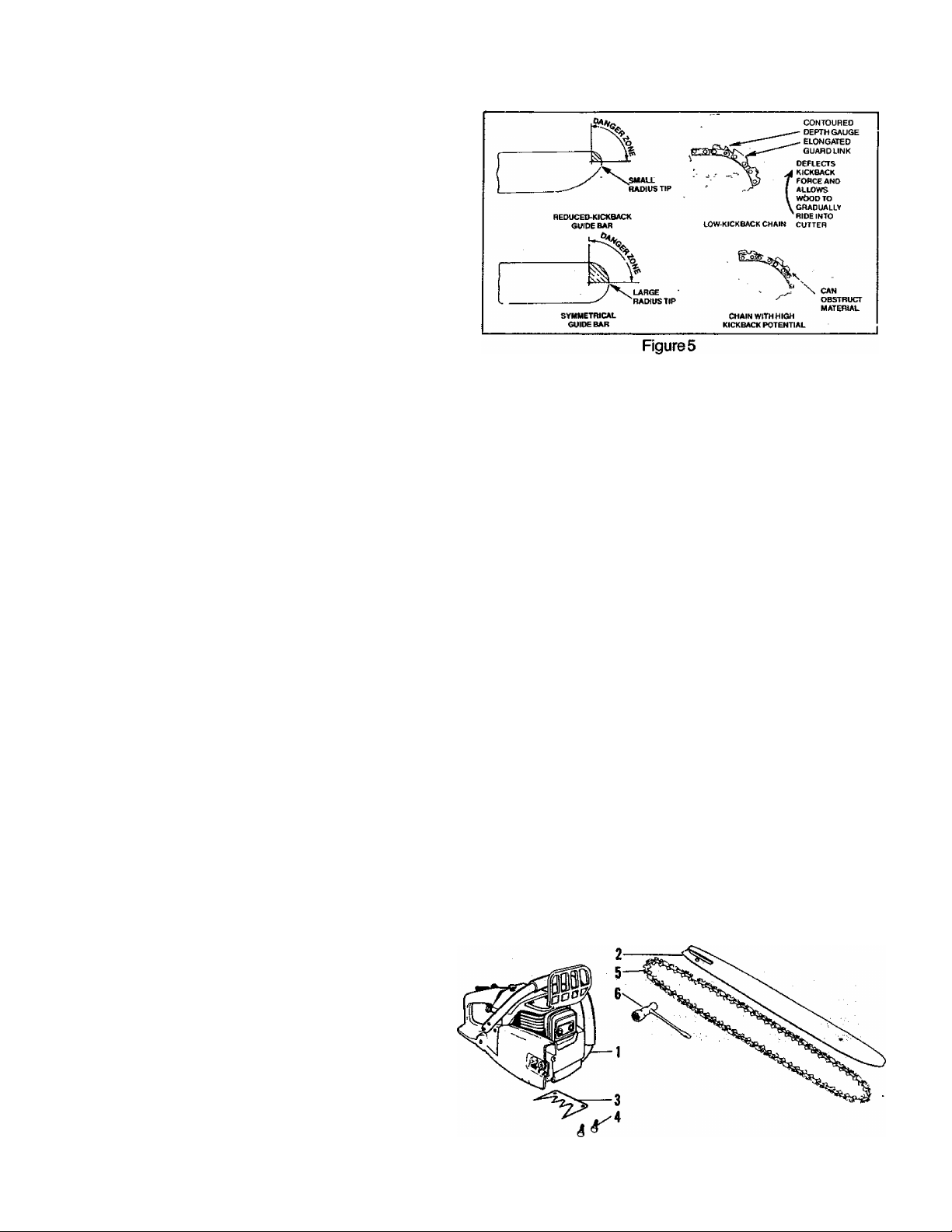
B. KICKBACK SAFETY FEATURES
— Reduced-Kickback Guide Bar, designed with a small
radius tip w^ich reduces the size of the kickback danger
zone on the bar tip. Figure 5. A Reduced Kickback
Guide Bar is one which has been demonstrated to
significantly reduce the number and seriousness of
kickbacks when tested in accordance with the safety
requirements for gasoline powered chain saws as set
by the American National Standards Institute, Inc.,
Standard B175.1 -1985.
— Low-Kickback Chain, designed with a contoured
depth gauge and guard link which deflect the kickback
force and allow wood to gradually ride into the cutter.
Figure 5. Low Kickback Saw Chain is chain which has
met the kickback performance requirements of ANSI
B175.1 (Safety Requirements for Gasoline-Powered
Chain Saws) when tested on a representative sample of
chain saws below 3B cubic inch displacement speci
fied in ANSI B175.1. (American National Standards
. Institute, Inc., Standard B175.1-1985).
-^Handguard, designed to reduce the chance of your left
hand contacting the chain if your hand slips off the front
handlebar.
— Position of front and rear handlebars, designed
with distance between handles and “in line” with each
other The spread and “in line” position of the hands
provided by this design work together to give balance
and resistance in controlling the pivot of the saw back
toward the operator if kickback occurs.
STATE AND LOCAL REQUIREMENTS.
Your saw is equipped with a temperature limiting
muffler and spark arresting screen which meets the
requirements of California Codes 4442 and 4443.
All U.S. forest land and the states of California, Maine,
Washington and Oregon require many internal com
bustion engines to be equipped with a spark arrestor
screen by law.
If you operate a chain saw in a state or locale where
such regulations exist, you are legally responsible
for maintaining the operating condition of these
parts. Failure to do so could subject you to liability
or to a fine. Muffler and spark arrestor maintenance
is found on page 17 & 18.
D.
CARTON CONTENTS
After you unpack the carton:
1. Check the contents against the list below.
2. Examine the items for damage.
3. Notify your dealer immediately if a part is missing
or damaged.
NOTE: A rattle like noise in a powerhead with an
empty fuel or oil tank is a normal condition, caused
by afilter moving against the wal I of an em pty tank.
KEY NO. CARTON CONTENTS:
Power Head
Guide Bar
‘Spur
‘Screw - Spur
Chain
Scrench
Loose Parts Bag (not shown)
Operator’s Manual (not shown)
QTY.
1
1
1
2
1
1
1
^WARNING
Do not operate the chain saw unless the safety devices
or their specified replacements are properly installed
and maintained according to the instructions in this
manual. Do not use any other guide bar and chain com
bination that is not equivalent to the original equipment
or not certified to comply with ANSI B175.1. Failure
to follow these instructions can result in serious per
sonal injury.
Page 7
PREPARING YOUR SAW FOR USE
A. GETTING READY
1. READ YOUR OPERATOR’S MANUAL
Your Operator’s Manual has been developed to
help you prepare your saw for use and to under
stand its safe operation. It is important that you
read your manual completely to become familiar
with the unit before you begin assembly or attempt
operation. Your Poulan® dealer is available to show
you how to operate your saw. Be sure to ask for his
assistance.
2. HAVE THE FOLLOWING AVAILABLE:
a. Protective gloves
b. Approved, marked, fuel container.
c. One gallon leaded or unleaded, regular
gasoline
d. 8 oz. (1/2 pt.), 2>cycle, air-cooled engine oil
(See page 9).
e. Bar and Chain Oil (See page 10.)
f. Scrench — provided with your unit. No other
tool is necessary for assembly. Use the long
end of the tool as a slotted screwdriver, the
small pipe end as a socket wrench, and the
larger pipe end to remove the spark plug.
B, ATTACHING THE SPUR (Standard Equipment on Some Units)
The spur is a special piece of equipment designed
to assist the cutting operation. When assembled to
the saw, the spur will dig into the tree or log and:
- relieve contact pressure adding ease to the saw
ing operation.
-allow the saw to be more easily rotated or pivoted
into the cut.
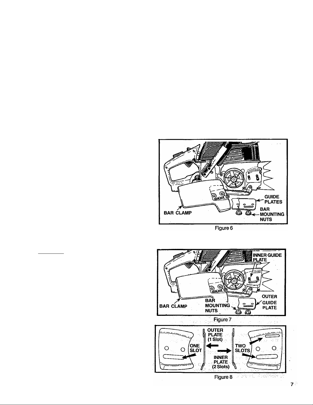
To Install:
1. Remove Bar Clamp Nuts, Bar Clamp and Guide Bar
Plates.
2. Align the spur over thé two holes on the bar clamp
side of the saw. Figure 6.
3. Insert the two screws and tighten evenly and sec
urely.
C. ATTACHING THE BAR AND CHAIN
CAUTION:! Wear protective gloves when han
dling or operating your saw. The chain is sharp
and can cut you even when it Is not moving!
• Your saw is equipped with a Reduced-Kickback
Guide Bar and a Low-Kickback Chain.
• Always use the Reduced-Kickback Guide Bar
and the Low-Kickback Chain specified for your
chain saw model, when replacing these parts.
Do not start engine without guide bar and chain
completely assembled. Otherwise, the ciutch can
come off and serious personal injury can result
Zi\ WARNING
1. Install the Inner Guide Plate overttie bar mounting
studs. Figure 7.
NOTE: Be sure the Inner Guide Plate curves or
flanges toward the saw frame away from the
Guide Bar. Figure 8.
Page 8
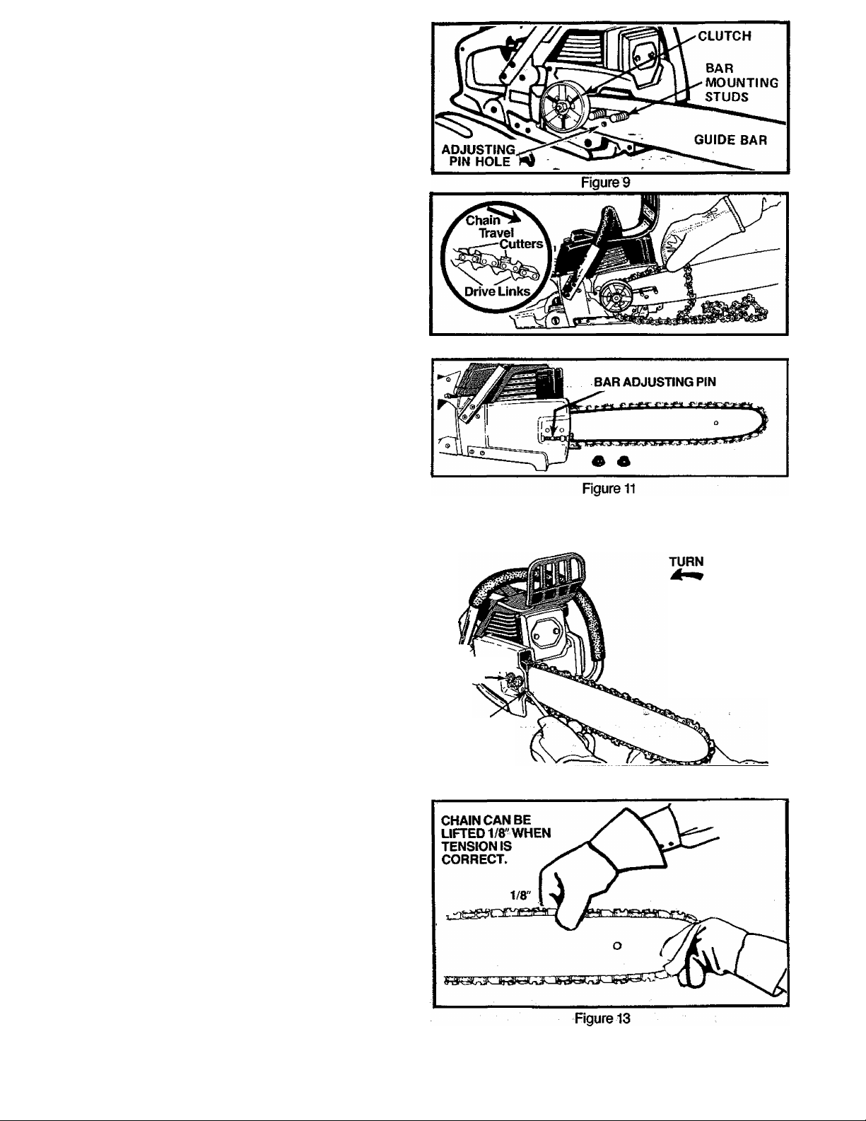
2. Mount the Guide Bar with the slotted end
over the bar mounting studs. Figure 9 .
NOTE: Be sure the Guide Bar is positioned
with the round hole below the large slot.
3. Hold chain with cutlers facing as shown in
Figure 10.
4. Place chain over and behind the clutch
drum onto the sprocket.
5. Slide Guide Bar to the rear of the saw as far
as possible.
6. Fit the bottom of the drive links between
the teeth in the sprocket.
7. start at the top of the bar and fit the chain
drive links into the groove around the Guide
Bar. Figure 10.
8. Pull the Guide Bar forward until the chain is
snug in the guide bar groove. Figure 11.
9. Install the outer guide plate. Figure? .
10. Slide the Bar Clamp over the mounting studs and fit
the bar adjusting pin (Rgure 11) into the adjusting pin
hole in the Guide Bar. Figure 9.
11. Replace the Bar Mounting Nuts and tighten
finger tight only.
NOTE: The Bar Clamp nuts must be slightly
loose to tension the chain correctly.
12. Follow “Chain Tension” instructions below.
Figure 10
D. CHAIN TENSION
• Correct chain tension Is very important:
—a loose chain will wear the bar and itself,
—a loose chain can jump off the bar while
you are cutting.
—a tight chain can damage the saw and/or
break.
• Chain tension is correct when the chain:
—can be lifted about 1/8” from the Guide Bar
at a point near the middle of the bar, and
—will move freely around the bar.
• The chain stretches during use, especialiy
when new; Check tension:
— each time thè saw is used
— more frequently when the chain is new
— as the chain warms up to normal operating tem
perature
1. Hold the tip of the Guide Bar up and turn the
Adjusting Screw just until the chain does not
sag beneath the Guide Bar. Rgure 12.
NOTE: Turn screw clockwise to tighten ten
sion. Turn screw counterclockwise to loosen
tension.
2. Check the tension by lifting the chain from
the Guide Bar at the center of the bar. Figure
13.
3. Continue turning the Adjusting Screw until
the tension is correct.
4. Hold the tip of the Guide Bar up and tighten
the Bar Clamp Nuts with the Scrench.
5. Recheck tension.
BAR
MOUNTING
STUDS
ADJUSTING
SCREW
TO LOOSEN
TENSION
TURN
TO TIGHTEN
TENSION
Figure 12
Page 9
E. ENGINE FUEL MIXTURE
• Your chain saw is powered by a two-cycle engine
which requires a fuel mixture of regular^asoline
(leaded or unleaded) and a high quality engine oii
specially made for 2-cycie air-cooled engines. The
internal design of the 2-cycie engine reqy ires lubrica
tion of moving parts. Lubrication is provided when you
use the recommended mixture of gasoline and oil.
• Gasoline must be clean and not over two months
old. After a short peiiod of time, gasoline begins to
chemically break down and will form compounds that
can cause hard starting and damage in 2-cycle en
gines.
• The correct measure of gasoline to oil is very im
portant.
—Too much oil in the mixture will foul the spark plug.
—Too little oil will cause the engine to overheat re
sulting in damage.
• Mix the fuel thoroughly in a container since
gasoline and oil do not readily combine. Do not
try to mix fuel directly in the fuel tank.
1. DONOTUSE:
• BIA Oii (Boating Institute of America)—
— Does not have proper additives for air-cooled,
2-cycIe engines and could cause damage.
• AUTOMOTIVE OIL—
— Does not have proper additives for 2-cycle
engines and could cause damage.
• GASOUNE CONTAINING ALCOHOL—
(High Test, Premium or Gasohoi)
—Stiffens critical carburetor fuel metering ele
ments and causes engine damage from over
heating.
— Increases vaporlock(causes hard starting).
— Attracts water causing corrosion damage.
Figure 14
2. USE THE FOLLOWING:
Two types of PoulanAA/eed Eater Engine Oil are
available — one blended to be mixed at a 16:1
ratio and the other ata 32:1 ratio.
'*OULaN/wE60 eXTEt'
tGAUO«
REGULAR
GASOÜHE
[leaded or
unleaded)
2 TWO
GALLCmS
regular
GASOLINE
(leaded or
unleaded)
+
(U2 PT}
0.1
16:1 Ratio
gNGINE OIL ^
^ —OR— ^
Awr GOOD
16:1
COOLED 2-CYCLt
.— Engine oil —
EOULAN/WEED
32:t Ratio
_ engine oil
jCAUTION:! If you use a 32:1 fuel mix, you must
use genuine PouianA/Veed Eater 32:1 Engine Oil
or engine damage can occur. Do not use a fuel
mix leaner than 32:1.
3. HOW TO MIX FUEL
Pour one-half of the gasoline into an approved,
a.
marked container. Do not try to mix oil and
gasoline directly in the fuel tank.
Add entire measure of 2-cycle Engine Oil.
b.
Mix.
c.
Add remainder of gasoline.
d.
Mix thoroughly for one minute.
e.
4. IMPORTANT POINTS
a. Use only recommended fuel mixtures.
b. Eliminate ail sources of sparks or flames in
the areas where fuel is mixed, poured, or
stored. There should be no smoking, open
flames or work that could cause sparks.
c. Use an approved, marked containerfor all
fuel purposes.
d. Mix and pour fuel in an outdoor area on bare
ground. Store fuel in a. cool, dry, well-
ventilated place. Gasoline vapors are harmful to
your health and can cause serious hazards
such as explosion and fire. Use a funnel or spout
when pouring fuel.
e. Avoid over filling the fuel tank. Allow % inch
V for expansion. Tighten Fuel Cap securely. Ftg-
ure 14.
f. Wipe up ail fuel spills. Wipe off any fuel spilled
on the saw. Completely dry the saw before
using.
g. Move at least 10 feet (3 meters) away from'
fuel and fueling site before starting the engine.
Page 10

F. BAR AND CHAIN OIL
• The Guide Bar and Cutting Chain require
continuous lubrication In order to remain in
operating condition. Lubrication is provided
by the automatic oiler system when the oil tank
is kept filled.
— Lack of oil will quickly ruin the Bar and
Chain.
—Too little oil will cause overheating shown
by smoke coming from the chain and/or dis
coloration of the Guide Bar Rails.
• Genuine Poulan® bar and chain oil is re
commended to protect your: unit against
excessive wear due to heat and friction.
Poulan® lubricant resists high temperature
thinning. If Poulan® bar and chain lube is not
available, use a good grade SAE 30 oil. Never
use wasteoil for this purpose.
• In freezing weather oil will thicken, making
it necessary to thin bar and chain oil with a
small amount of Diesel Fuel #1 or
Kerosene. Bar and chain oil must be free flow
ing for the oil system to pump enough oil for ad
equate lubrication.
1. USE THE FOLLOWING;
2. HOWTO FILL THE OIL TANK
a. Stop the engine.
b. Turn saw on its side with oil cap up. Figure 15.
c. Loosen cap slowly and wait for pressure in the
tank to be released before temoving the cap.
d. Fill the oil tank,
e. Replace the oil cap securely.
3. IMPORTANT POINTS TO REMEMBER
a. Prime the oil pump on a new saw or a saw that
has been unused for an extended period of
time. Pump the manual oiler slowly several times.
Start the engine and allow the chain to run. Stop the
engine and check for an even flow of oil on the
chain. Repeat this procedure until oil is visible on
the chain.
b. Fill the oil tank each time you refill the fuel
tank to ensure there will be sufficient oil for the
chain whenever you start and run the saw.
c. Thesawwiiluseabout1/2tankofchainoiifor
each tank of fuel mixture. If less oil is used,
check for a plugged oil hole in the guide bar.
d. It is normal for a small amount of oil to appear
under the saw after the engine stops. This is
due to oil draining from the bar and chain when
not in use.
30"F or above—Lubricant—undiluted.
SO'^-O^F—95% lubricant to 5% Diesel Fuel
#1 or Kerosene.
Below 0°F—90% lubricant to 10% Diesel
Fuel #1 or Kerosene.
USING YOUR SAW
A. CONTROL DEVICES
Understanding the control devices on your saw
is an important part of learning how to properly
and safely operate the unit. Figure 16.
THROTTLE
DETENT
BUTTON
CHOKE
THROTTLE
LOCKOUT
MANUAL
OILER
START/STOP^
SWITCH
TRIGGER
START
STOP
START/STOP
SWITCH
HALF
FULL-i i;:
CHOKE
2. The two-position Choke helps to start the saw by
■ controlling the air flow to the fuel system.
3. The Trigger accelerates and controls the speed of
the engine and is designed; to be used: with the
Throttle Lock.
i
OFF
4. The Throttle Lock is a control feature which pre
vents the Trigger from becoming accidentally en
gaged. The Throttle Lock must be pressed before
the Trigger can be activated.
5. The Throttle Detent Button holds the Throttle Lock
and Trigger in position while the engine is being
started. Release tiie Throttle Detent Button after the
engine is started by lightly squeezing the trigger.
6. The Manual Oiler is placed to be operated by your
right thumb. Use the manual oiler to supplement the
automatic oiler;
Figuréis
1. The ignition Switch is a toggle switch which is
moved up for the "Start" position and moved down
for the “Stop” position.
10
—during a long felling cut
—when cutting into a log or tree which is greater in
■ anytime an additional supply of oil is desired.
Page 11

STARTING INSTRUCTIONS
1.BASIC PROCEDURE
a. Set the saw on flat ground making certain the
saw chain is free tatum without contacting any
object. Figure 17.
b. Move ignition switch to the “Start” position.
c. Push down on the throttle lockout, squeeze the
trigger, press and hold down the throttle detent
button, then slowly release the trigger.
d. Adjust choke according to “Starting Pro
cedure for Varying Conditions” below.
e. Hold front handlebar with left hand & place right
foot through rear handid to stablize saw.
f. Pull starter rope quickly, using no more than
15-18 inches of rope per pull. Using the full length
of the starter rope may cause it to break. Do not let
the starter rope snap back. Hold the handle and let
the rope rewind slowly.
g. Release the throttle detent button after engine
starts, allowing the engine to idle. The chain must
not move when the engine runs at idle speed. If cor
rection is required, refer to “Carburetor Adjust
ments,” page 20.
h. Stop engine by moving the Ignition switch to the
“STOP” position (Figure 16).
^WARNING
Always wear gloves; safety footwear; snug-fitting
clothing; and eye, hearing, and head protection
devices when operating a-ehain saw.
vii^RNING
Avoid bodily contact with the muffler when start
ing or using a warm engine to avoid serious burns.
2. STARTING PROCEDURE FOR VARYING CONDITIONS
Squeeze trigger
X X
X
X X
X
CONDITIONS
a. Cold Engine
b. Warm Engine
c. Refueled Engine after
X
X
X
Puit choke knob
X X
chtAeoff
X X
Move ignition
switch to start ; tofuilchoke
Press llinttte Press throttie Puli starter rope Pushchoke knob: Puif Starter rope
lockottlsnd detent button untli engine tires in until engine runs to release
squeeze triggerrelease trigger throttle detent
X 3-5 times X
X X
X 3-5 times X
running out of gas
d. Flooded Engine
e. Cold Weather Starting
X
X X
choke off
X X
X X 3-5 times
half choke'
(out of cut)
X X
X
X
*Allow engine to warm-up (1-2 min.) on half-choke, then move choke to the “Off" position. Do not cut with the choke at the
“On” or “Half” position. Figure 15.
TYPES OF CUTTING
BASIC CUTTING TECHNIQUE
A.
1. IMPORTANT POINTS.
Cut wood only. D6 not cut metal, plastics,
a.
masonry, non-wood, building materials; etc.
Stop the saw if the chain strikes a foreign
b.
object. Inspect the unit and repair or replace
parts as necessary.
c. Keep the chain out of dirt and sarid. Even a
thus, increase the possibility of kickback.
2. UNDERSTAND REACTIVE FORCES
Pinch-Kickbackand Pull-In occur when the chain
is suddenly stopped by being pinched, caught, or
by contacting a foreign object in the wood. This
results in a reversal of the chain force u^d to cut wood
and causes the saw to move in the opposite direction of
chain rotation. Either reaction can result in loss of con
trol and possible serious personal injury.
Kickback can occur when the moving chain contacts an
object at the upper portion of the tip of the g ulde bar or
when the wood closes in and pinchesthe saw chain in
the cut. Contact at the upper portion of the tip of the
stop the chain for an instant. The result ts a iightning
fast, reverse reaction which kicks the guide bar up and
back towaid the operator. If the saw chain is pinched
along the top of the guide bar, the guide har can be
drivenrapidiybacktowardtheoperatqr.BWheroHhese
reactions can cause loss of saw control wb/cb can
resuit in serious personai injury.
A KICKBACK WARNING
• Pinch-Kickback
—bccu rs when the chain, on top of the bar is suddenly
stopped when the top of the bar is used for cutting.
— rapidly drives the saw straight back toward the
operator
11
Page 12

• Pull-In —
— can occur when fhe chain on the bottom of the
bar is suddenly stopped.
—pulls the saw rapidly forward.
3. PROCEDURE
Practice cutting a few small logs using the following techni
que to get the “feel” of using your saw before you begin a
major sawing operation.
a. Accelerate the engine to full throttle just before
entering the cut by squeezing the throttle trigger.
b. Begin cutting with the saw frame or spur against
the wood. Figure 18.
c. Keep the engine at full throttle the entire time you
are cutting.
d. Allow the chain to cut for you; exert only light
downward pressure. If you force the cut, damage to
the bar, chain, or engine can result.
e. Release the throttle trigger as soon as the cut is
completed} allowing the engine to idle. If you run the
saw at full throttle without a cutting load, unnecessary
r
wear can occur to the chain, bar, and engine.
f. Do not put pressure on the saw at the end of the cut
to avoid losing control wherrthe cut is complete.
g ■ Stop the engine before setting the saw down after
cutting.
Figure 18
B. TREE FELLING TECHNIQUES
1. PLAN YOUR SAWING OPERATION CARE
FULLY IN ADVANCE
a. Clear the work area. You need a clear area all
around the tree where you can have secure
footing.
b. Study the natural conditions that can cause
the tree to fall in a particular direction:
1. ) The WIND direction and speed
2. ) The LEAN of the tree
3. ) WEIGHTED with BRANCHES on one side
4. ) Surrounding TREES and OBSTACLES
c. Look for decay and rot. If the trunk is rotted,
it could snap and fall toward the operator.
d. Check for broken or dead branches which
could fall on you while cutting.
e. Make sure there Is enough room for the tree
.....
to fail. J\/laintaining a distance - of . 2V2 tree
- “lengths from the nearest person or other ob
jects. Engine noise may drown out warning
call-
f. Remove dirt, stones, loose bark, nails,
staples, and wire from the tree where cuts
are to be made.
DON’T PUT YOURSELF IN THESE POSITIONS
g. Plan to stand on the up-hill side when cut
ting on a slope.
h. Plan a clear retreat path to the rear and
diagonal to the line of fail. Figure 20.
2. FELLING SMALL TREES —LESS THAN 6"
IN DIAMETER
a. If you know the direction of fall:
1. ) Make a single felling cut on the side away
from the direction of fall.
2. ) Cut all the way through.
3. ) Stop the saw, put it down, and get away
quickly on your planned retreat path.
b. If you are not sure which way the tree will fall,
use the notch method described for felling large
trees.
Awarning
DO NOT CUT: / ^ '
— near electricai wires or buildings.
— if you do not know the direction of tree fall.
—at night since you will not be able to see well.
— during bad weather — strong wind, snow, rain,
etc.
12
Page 13

3. FELLING LARGE TREES
6' DIAMETER
OR MORE
The notch method is used to cut large trees. A
notch is cut on the side of the tree in ^e desired
direction of fall. After a felling cut is made on the
opposite side of the tree, the tree will tend to fall
into the notch.
NOTE: if the tree has large buttress roots, remove
before making the notch. Cut into the buttresses
vertically, then horizontally. Figure 19
a. Make the notch cut. Figure 21 .
1. ) Cut the bottom of thè notch first, through 1 /3
of the diameter of the tree.
2. ) Complete the notch by making frie slant cut.
3. ) Remove the notch of wood.
b. Make the felling cut on the opposite side of the
notch about 2" higher than the bottom of the
notch.
c. Leave enough uncut wood between the felling
cut and the notch to form a hinge. Rgure 22.
NOTE: The hinge helps to keep the tree from
twisting and falling in the wrong direction.
d. Use a wedge if there is any chance that the tree
will not fall In the desired direction.
Figure 21
Figure 22
/U WARNING
Stay on the uphill side of the terrain to avoid the
tree rolling or sliding downhill after it is felled.
NOTE: Before the felling cut is complete, drive
wedges to open upthe cut when necessary to con
trol the direction of fall. Use wood or plastic wedges
but never metal, to avoid kickback and chain
damage.
e. Be alert for signs that the tree is ready to fall:
1. ) cracking sounds
2. ) widening of the felling cut
3. ) movement in the upper branches.
C. BUCKING
Bucking is the term used for cutting a fallen tree
to the desired log size.
1. IMPORTANT POINTS
a. Cut only one log at a time.
b. Cut shattered wood very carefully. Sharp
pieces of wood could be flung toward the
operator.
c. Use a sawhorse to cut small logs. Never
allow another person to hold the log while cut
ting and never hold the log with your leg or foot.
d. Give special attention to logs under strain to
prevent the saw from pinching. Make the first
cut on the pressu re side to retieye the stress
on the log. Figure 23 -
e. Do not cut in an area ^ere logs, limbs and
roots are tangled such as in a blown down
area: Drag the logs intp a clear area before cut
ting bypulling put expose!^ and cleared logs
first.
f. As the tree starts to fall, stop the saw,' put it
down, and get away quickly on your planned retreatpath.
g. Be extremely cautious with partially fallen trees
that may be poorly supported. When a tree
doesn’t fall completely, set the saw aside and
pull down the tree with a cable winch, block and
tackle or tractor. Do not cut it down with your
sawto avoid injury.
Make the first bucking cut 1/3 of the way
through the log and finish with a 2/3 cut on
the opposite side. As the log is being cut, it will
tend to bend. The saw can become pinched or
hung in the log if you make the first cut deeper
than 1 /3 of ttie diameter of the log.
13
Page 14

A WARNING
Never turn the saw upside down to undercut. The
saw cannot be controlled in this position.
2. TYPES OF CUTTING USED Figure 24:
—Overcutting - begin on the top side of the log
with spur or saw frame against the log; exert
light pressure downward. ''
— Undercutting - begin on the under side of the
log with the top of Uie saw against the tog; exert
light pressure upward. During undercutting, the
saw will tend to push backiat you. Be prepared
for this reaction and hold the saw firmly to main
tain control.
/JaWARNING
If saw becomes pinched or hung in a log, don’t try to
force it out. You can lose control of the saw resulting In
personal injuryand/ordamageto the saw. Stop the saw,
drive a wedge of plastic or wood into the cut untli the
saw can be removed easiiy. Figure 25. Restart the saw
and carefully reenter the cut. Do not use a metal wedge
to avoid kicl^ackand chain damage.
3. BUCKING—WITHOUT A SUPPORT
a. Overcutwith a 1/3 diameter cut
b. Roll log over and finish with an overcut.
4. BUCKING — USING ANOTHER LOG AS A SUPPORT Figure 26.
AWARNING
Do not stand on the log being cut. The cut portion
will roll down hill.
In area A:
a.
1. ) Undercut 1 /3 of the way through the log.
2. ) Finish with an overcut
In area B;
b.
1.) Overcut, 1/3 of the way through the log.
2j Finish with an undercut '
5. BUCKING —USING A STAND Figure 27.
a. In area A:
1. ) Undercut 1 /3 of the way through the log.
2. ) Finish with an overcut
b. In area B:
1. ) Over cut 1 /3 of the way through the log.
2. ) Finish with an undercut
D. DEBRANCHING AND PRUNING
• Work slowly, keeping both hands on the saw
with a firm grip. Maintain secure fppting and bal
ance.
• Watch out for springpoles. Use extreme caution
when cutting small size iimbs. Slender material may
catch the saw chain and be whipped toward you or
pull off balance.
14
Be alert for sprlngback. Watch out for branches
that are bent or under pressure as you are cutting to
avoid being struck by the branch or the saw when the
tension in the wood fibers is released.
Keep a clear work area. Frequently clear branches
Page 15

¿V. WARNING
Never climb into a tree to debranch or prune. Do not
stand on ladders, platforms, a log or in any position
which can cause you to lose your balance or control of
the saw.
1. PEBRANCHING
a. Always debranch a tree after it^is cut down.
Only then can debranching be done safely
and properly.
b. Leave the larger lower limbs to support the
tree as you work.
c. Start at the base of the felled tree and work
towards the top, cutting branches and
limbs. Remove small limbs with one cut. Fig
ure 28.
d. Keep the tree between you and the chain.
Cut from the side of the tree opposite the
branch you are cutting.
e. Remove larger, supporting branches with
the 1 /3,2/3 cutting techniques described in
the bucking section.
¿ ; 1.) Start with an overcut
2.) Finish with an overcut
f. Always use an overcut to cut small and
freely hanging limbs. Undercutting could
cause limbs to fall and pinch the saw.
Zi^WARNING
Be alert for and guard against kickback. Do not allow
the moving chain to contact any other branches or
objects at the nose of the guide bar when debranching
or pruning. Allowing such contact can result in serious
personal injury.
2. PRUNING
a. Limit pruning to limbs shoulder height or
below. Do not cut if branches are higher than
your shoulder. Get a professional to do the
job.
b. Refer to Figure 29 for the pruning tech
nique.
1. ) Undercut 1 /3 of the way through the limb
near the trunk of the tree.
2. ) Finish with an overcut farther out from the
trunk.
3. ) Keep out of the way of the falling limb.
4. ) Cut the stump flush near the trunk of the
tree.
MAINTENANCE
A good maintenance program of regular inspection
and care will increase the service life and help to main
tain the safety and perforrhanceofyoursaw.
• Make ail adjustments or repairs (except car
buretor adjustments) with:
^ spark plug wire disconnected
—engi ne cool as bppo^d to a unit that has just
been run.
• Check the saw for loose bolts, screws, nuts and
fittings regularly. Loose fasteners can cause an
unsafe condition as well as damage to your saw.
•
^WARNING
Have all chain saw service (other than the items listed
in the maintenance section of this manual) performed
by a qualified service dealer.
Read
SPECIAL SAFETY SECTION
FREQUENTLY
15
Page 16

A. GUIDE BAR AND CHAIN
Increase the service life of your Guide Bar and
Chain by:
—Using the saw properly and as recommended
in this manual.
—Maintaining correct Chain Tension, paged.
—Proper lubrication, page 10.
—Regular maintenance as described in this sec
tion.
1. CHAIN MAINTENANCE
• Sharpen the chain when:
— Wood chips are smdil and powdery. Wood
chips made by the saw chain should be
about the size of the teeth of the chain.
— Saw has to be forced through the cut.
— Saw cuts to one side.
r ■
4.) Sharpen cutters.
a. ) Support the square rod on the file holder
(with 7/32" round file) on cutter top plate.
Figure 30.
b. ) Hold the file holder level with the 30° guide
mark paraiieUo the center of the chain
and lower file handje 10°. Figure 30.
c. y File from inside toward outside of cutter,
straight across, on forward stroke only. Use
2 or 3 strokes per cutting edge. Figure 31.
d. ) Keep all cutters the same length. Figure
32.
e. ) File enough to remove any damage to cut
ting edge(side &top plate) of cutter. Figure
32.
f. ) Fite P72S chain to meet specifications
shown in Figure 33.
ICAUTION: I Always wear gloves when hand
ling the chain. The chain can be sharp enough to
cut you even though it may be too dull to cut
wood.
a. CLEAN TREE SAP FROM THE CHAIN
BEFORE IT IS SHARPENED:
1. ) Soak chain in a petroleum based solvent
or a detergent and water solution
2. ) Dry chain thoroughly.
3. ) Immerse the clean chain In light oil until oil
seeps into the rivet holes.
NOTE: Do not run a chain which has been
cleaned without lubricating it first.
b. SHARPENING INSTRUCTIONS
Items required:
Gloves
7/32” dia. file
6” file holder
Depth Gauge Tool
Flat file
Vise
Maintain the proper hook angle according to the
manufacturer’s specification for the chain you are
using. Too much hook angle will increase the chance
of kickback which can result in serious personal
injury. Figure 33 & 35.
ZL WARNING
5.) Correct Depth Gauges
a. ) Place depth gauge tool over each cutter
depth gauge. Figure 34.
b. ) File level with the flat file If depth gauge is
higher than the depth gauge tool.
c. ) Maintain rounded front corner of depth
gauge with a flat file. Figure 34& 35.
NOTE: The very top of the depth gauge
should be flat with the front half rounded
off with a flat file.
WARNING
Depth gauge tool is required to insure proper depth
gauge. Filing the depth gauge too deep will increase
the chance of kickback which can result in serious
personal injury.
16
Figure 32
Figure 34
ROUNDED
CORNER
Figure 35
TOO MUCH SQUARED
HOOK ANGLE qfF CORNER
\
WRONG WAY
Page 17

b. CHAIN REPLACEMENT
1. ) Replace the chain when cutters or links
break.
2. ) See a qualified service dealer to replace
and sharpen individual cutters for^atching your chain.
3. ) Always replace the worn sprocket when
installing a new chain to avoid excessive
wear to the chain.
2. GUIDE BAR MAINTENANCE
• Conditions which can jcequire guide bar
maintenance:
—saw cuts to one side
—saw has to be forced through a cut
—inadequate supply of oil to bar and
chain.
Check the condition of the guide bar each
time the chain is sharpened. A worn guide
bar win damage the chain and make cut
ting more difficult.
Replace the guide bar when:
—the inside groove of the guide bar rails is
worn.
—the guide bar is bentorcracked.
a. Remove the guide bar to service.
b. Clean oil holes at least once for each
five hours of operation.
c. Remove sawdust from the guide bar
groove periodically with a putty knife or
a wire. Figure 36.
d. Remove burrs by filing the side edges
of the guide bar grooves square with a
flat file.Figures/.
e. Restore square edges to an uneven rail
top by filing with a flat file. RgureSZ.
M ilfl lU
B, IGNITION AND EXHAUST SYSTEMS
• Carbon deposits will build up on exhaust ports,
spark arrestor, muffler, and spark plug as the saw
is used. All of these parts should be cleaned at the
same time to prevent engine damage, overheating,
loss of power, and hard starting.
• Clean parts:
—as required
^at least once for each 25-30 hours of opera
tion
1. COOLING AND EXHAUSTSYSTEM
• Carbon build-up on the cooling and exhaust
system can cause the engine to lose power
in a cut.
• Keep the spark arrestor clean at all times.
• Replace the spark arrestor when breaks in
the screen are found.
Items required:
—wire brush
— 3/8"wrench
— hardwood stick
CORRECT
GUIDE BAR
GROOVE
a. Disconnect the spark plug.
b. Remove the muffler, baffles, and screen. Fig-
c.
d.
WORN GROOVES
Figure 37
ure38.
Puli the starter rope until the piston moves far
enough to close the exhaust ports.
Scrape the carbon deposits from the exhaust
ports and surrounding exhaust chamber using a
hardwood stick. Figure 39.
FILE EDGES
SQUARE
[CAUTION: iDo not use a metallic scraping tool
to avoid damage to the piston.
e. Blow out loosened carbon with compressed air.
f. Glean the spark arrestor screen with a wire
brush or replace if breaks in the screen afe
found.
g. Reassemble muffler parts.
17
Page 18

2. SPARKPLUG
• Maintenance is indicated when the engine is
hard to start.
• Keep the spark plug: ^
—clean
— properly gapped (.025")
SPARKPLUG
CHAMPION ed-8Y
Items Required: Small brush, such asa tooth brush,
or a pocket knife.
a. Remove the carburetor cover.
b. Pull the rubber connector from the spark plug
and remove the spark plug from the cylinder.
c. Clean deposits from the electrodes of the spark
plug with a small brush oír a pocket knife.
NOTE: Be careful when removing, cleaning,
gapping and replacing the spark plug. If it is
damaged, it will not work properly and must be
replaced.
C. STARTER ROPE REPAIR AND REPLACEMENT
• A starter rope that breaks next to the pulley
can be repaired.
• Replace the starter rope if the rope breaks more
than 2-3 Inches away from the pulley as the rope
will be too short to repair properly.____________
A WARNING
Always wear eye protection when servicing the
starter rope. The recoil spring beneath the pulley
is under tension. If the spring pops out, serious
personal injury can result.
NOTE: The recoil spring, located beneath the
pulley, is under tension. If spring pops out, it
will require considerable time and effort to
reinstall. For this reason, you may want to let a
qualified service dealer handle this repair. If you
do try to repair the starter rope and the recoil
spring pops out take the unit to your dealer.
1. Remove the four screws on the side of the fan
housing. Figure 41.
GAP .025"
Figure 40
d. Set the gap between the electrodes to .025
using a wire or flat gauge. Figure 40.
e. Replace the spark plug in the cylinder and attach
the rubber connector.
f. Replace carburetor cover and knob.
NOTE: The tension on the starter spring will be
released if the rope has broken.
4. Turn the pulley counterclockwise until the spring
tension is released.
5. Remove the pulley screw in the center of the pul
ley. Figure 43.
6. Lift the pulley carefully while gently twisting it
counterclockwise , and remove the old
rope.
7.. Move away from the fuel tank and melt the end of the
new rope to go into the pulley.
8. Allow the melted end to drip once,* then while the
rope is still hot, pull the melted end through a rag
to obtain a smooth, pointed end.
9. Feed the rope through the round starter hole in the
the fan housing. Figure 43.
10. Snake rope inside pulley, then through topside pulley
hole by pushing the rope from the underside hole
with a small round ob|ect, such as a Phillips
screwdriver. See insert. Figure 43.
18
"- NOTE: Notice the different iengths bf the screws
and their proper locations while removing the
screws.
2. Remove the fan housing.
3. If the starter rope is not broken, release the spring
tension by pulling about 12 inches of rope from
the pulley and catch the rope in the notch as
shown. Figure 42.
Page 19

11.
Wrap rope counterclockwise around
pulley ratchet and tuck loose end back under rope
leaving a 3/8-1/2 inch tail. Pull tightly around ratchet.
Figure 43.
12.
Pull the rope tightly around ratchet and wrap around
the pulley clockwise ^
13.
Set the pulley into the housing; push it down and
engage the spring.
14.
Replace and tighten the pulley-screw.
15.
Pull out 12 inches of rope and catch the rope
in the notch in the pulley. Figure 43 ,
16.
Turn the pulley 3 complete turns clockwise
winding up the spring.
17.
Hold the pulley, pull the starter rope to the full
extent of length then letThe rope rewind slowly.
18.
Replace fan housing with the four screws in their
proper location.
D. CLUTCH AND DRUM/SPROCKET
Awarning
Do not Start engine without Guide Bar, Chain, and Bar
Clamp Housing completely assembled. The clutch can
come off without the guide bar and chain completely
assembled and serious injury can result. Do not loosen
and spin the clutch off the crankshaft with a power tool.
The clutch shoes and drum can separate causing the
clutch to violently fly apart and serious personal injury
can result.
• Take the saw to a qualified service
dealer for full clutch inspection and service after
each 100 hours of operation, /t is recommended
that you do not try to service the clutch or
drum/sprocket yourself unless you are a competent
small engine mechanic and have the proper clutch
service tools. Proper disassembly and repair of the
clutch is extremely important to the life of the engine
and the safety of the operator.
» Clutch maintenance is required when:
—the chain continues to turn while engine idles
after the idle speed screw has been adjusted
to its capacity,
— slippage occurs during a cut.
—a chattering noise occurs during cutting.
• Clean the clutch, drum/sprocket and surround-
. ing area daily during heavy use of the saw.
^ Check to see that the clutch drum turns freely and
smoothly.
i Inspect the drum/sprocket regularly for wear. A
worn sprocket will make the chain run erratically
and will shorten the life of the bar and chain. Figure
45.
» Replace the drum/sprocket whenever a new
chain is installed in order to gain the full life expec
tance of the chain. Use the following procedure:
9/16" Socket Wrench
3/4" Socket Wrench
2. Remove the bar clamp, outer guide plate, guide
bar, and chain. Figure 46.
3. Remove the fan housing.
4. Use a 9/16" socket wrench on the flywheel nut to
keep the crankshaft from moving. Figure 47.
NOTE: Place the socket handle forward as shown
in Figure 47.
Figure 46
1. Remove the carburetor cover and pull the spark
plug away from the rubber connector.
Figure 47
KEEP
CRANKSHAFT
FROM MOVING
19
Page 20

CLOCKWISE
REMOVE CLUTCH
INSTALL CLUTCH
COUNTERCLOCKWISE
Figure 48
E. CARBURETOR ADJUSTMENTS
5. Remove the clutch with a 3/4" socket or end wrench
maclockwise direction. Figure 48.
ICAUTIO^ Do not remove the clutch with a
punch or a powerful tool to avoid damage or
breakage to the clutch; •
6. Remove worn drum/sprockejt-and replace.
7. Install clutch in a counterclockwise direction. Rg-
ure48.
8. Hold flywheel by hand and tighten clutch with 3/4
socket wrench.
NOTE: Do not hold a wrench on the flywheel nut
when replacing the clutch. This could loosen the
flywheel nut.
9. Reinstall fan housing, bar chain and bar clamp.
• The carburetor has been adjusted at the factory for
sea level conditions. Adjustment may become nec
essary if the unit is used at significantly higher al
titudes or if you notice any of the following conditions:
—Chain moves with the engine at idle speed.
— Loss of cutting power which is not corrected
by air filter or muffler screen cleaning.
— Engine dies or hesitates when it should accel
erate.
• Permanent damage will occur to the engine if in
correct carburetor adjustments are made. It Is
best to let a qualified service dealer make carburetor
adjustments. If you choose to make the adjustments
yourself, follow the procedu re below very carefu lly.
TVIIARNING
The chain may be moving during this procedure.
Wear your protective gear and observe all of the
safety precautions.
1. PREPARATION
- a. Stop engine.
b.
Use a fresh fuel mixture wifii proper gasoline/oil
ratio. '■■■■
c.
Place the saw on a solid, flat surface and nriake
sure the chain will not contact any object,
d. Locate the three (3) Carburetor adjusting screws
located on the fan housing side of the saw. Figure
49.
Turn the Low Speed Mixture Screw and the
e.
------
High Speed Mixture Screw Clockwise
just until they stop. Do not turn Vie screws until
they qre tight as you m^ damage the needle
seats.
f. Turn the Low Speed Mixture Screw and the
High Speed Mixture Screw one full turn coun-
tercloclwise
2. IDLE SPEED ADJUSTMENT— I
a. Start the engine and allow to idle.
b. Adjust if the engine dies or stops by turning the
ldleSpeedScrew1/2turncioclwise
NOTE: To increase idle
Speed Screw clockwise
idle speed, turn the Idle
terclockwise
c. Run the engine for a few minutes to bring it up
to operating temperature.
speed,
Speed Screw coun-
turn the idle
. To decrease
NOTE: The engine must be at operating temper
ature for proper adjustments to be made.
3. LOW SPEED MIXTURE ADJUSTMENT
a. Turn the Low Speed Mixture Screw slowly
clockwise until the RPM starts to
drop. Note the position.
b. Turn the Low Speed Mixture Screw coun
terclockwise until the RPM speeds up
, . and startsto drop again. Note the position.
c. Set the Low Speed MIxture Screw at the mid
point between the two positions.
4. IDLE SPEED ADJUSTMENT—II
a. Allow engine to idle.
b. Adjust if the chain is turning by turning the Idle
Speed Screw counterclockwise
c. Squeeze the throttle trigger: the saw should ac
celerate without hesitafing.
NOTE: It may be necessary to recheck the low
speed mixture setting after the idle speed has
been reduced by repeating “Low Speed Mixture
Adjustment” as in step 3 above.
20
Figure49
5. HIGH SPEED MIXTURE ADJUSTMENT
a. Make a test cut.
b. Adjust if the saw smokes or seems to have low
power in the test cut by turning the High Speed
Mixture Screw 1/16th of a turn clockwise^^.
c. Repeat test cut.
d. Repeat adjustrnerit until the saw runs smoothly.
Page 21

CAUTION:I Never set the High Speed Mixture
Screw less than 7/8 turn open. This is too lean
a setting and will damage your engine.
6. IDLE SPEED ADJUSTMENT—III
Recheck for proper idle mixture setting. ^
NOTE: It may be necessary to repeat Idle Speed
Adjustment — I and Low Speed Mixture Adjust
ment.
7. CHECK ACCELERATION
Adjust if there is a slight hesitation, by turning the
Low Speed Mixture Screw 1 /16 of a turn at a time
ojunterclockwise until you have smooth
acceleration.
NOTE: Check to be sure the chain is not turning
when engine is idling.Jf chain moves at idle speed,
repeat Idle Speed Adjustment—II.
AIR FILTER
• A dirty air filter:
— reduces cutting power
— increases fuel consumption
• Clean the Air Filter:
—frequently, especially under very dusty condi
tions.
—always after 10 tanks of fuel mixture or 5 hours
of operation, whichever is less.
G. COUNTER-VIBE® ANTI-VIBRATION SYSTEM
This saw is equipped with a counter vibration
system consisting of 5 isolator mounts. Figure 51.
The Isolator Mounts reduce engine and chain vibration
similar to the way shock absorbers on a car reduce jolts
and bumps in the road.
1 CAUTION^ Never operate the unit without the
air filter in place to avoid damage to the engine.
Items Required: soft bristled brush, such as a paint
brush.
1. Clean off the carburetor cover and the area around
it.
2. Close choke to prevent dirt from entering the car
buretor.
3. Remove the carburetor cover. Figure 50.
4. Removetheairfiltercarefully.
5. Soak the filter in soap and water.
CAUTION:! Do not use gasoline or other flam
mable liquid to clean the filter to avoid creating
afire hazard.
6. Brush away all dust and debris from the filter.
7. Allow filter to dry.
8. Brush away all debris from surfaces which were
covered by the carburetor cover.
9. Replace filter and carburetor cover.
1. Check isolators each time the saw is used.
2. Replace isolators when:
—vibration increases
—mounts develop an out of round or swollen
shape usually caused from exposure to gasoline
and oil for long periods of time.
3. Replace ail five isolators when a failure to one
occurs.
H. STORAGE
When your saw is to be stored for over 30 days al
ways:
1- Drain fuel tank in a safe manner (see “Impor
tant Points,” page 9).
2. Start engine and allow to run at idle speed
until the engine stops.
NOTE: This will remove most of the fuel from the
fuel system.
CAUTION:I Wear protective gloves when han
dling the chain. The chain is sharp and can cut
you even when it is not moving.
3. Drain oil tank.
4. Remove,, clean, and dry the bar and chain.
5. Store the chain in a container filled with oil to pre
vent rust.
6. Apply a coating of oil to the entire surface of the bar
and wrap it in heavy paper, cloth or plastic.
7. Clean the outside surfaces of the engine.
8. Store frie saw in a dry place out of the reach of chil-.
dren and away from where fuel vapors can reach
open flames from hot water heaters, furnaces, etc.
21
Page 22

I. TROUBLE SHOOTING CHART
TROUBLE
ENGINE WILL NOT START
ENGINE WILL NOT IDLE
PROPERLY
ENGINE WILL NOT
ACCELERATE, LACKS
POWER OR DIES
IN THE CUT
ENGINE SMOKES
EXCESSIVELY
ENGINE RUNS HOT
OIL INADEQUATE FOR
BAR AND CHAIN
LUBRICATION
CHAIN MOVES AT
IDLESPEED
CHAIN DOES NOT MOVE
WHEN ENGINE IS
ACCELERATED
CAUSE
1. ignition Switch off.
2. Fuel tank empty.
3. Spark Plug not firing.
4. Fuel not reachirjg carburetor.
5. Engine flooded.
6. Compression low.
1. Idling speed set too tow.
2. Idle speed set too high.
3. Low speed screw requires adjustment.
4. Crankshaft seals worn.
5. Compression tow.
1. Carburetor requires adjustment.
2. Air filter dirty.
3. Spark Plug fouled.
4. Carbon build-up.
5. Low Compression.
1. Choke partially on.
2. High speed needle requires adjustment.
3. Airfitterdirty.
4. Oil rich fuel mixture.
5. Crankcase leak.
1. Fuel Mixture Incorrect.
2. Spark Plug Incorrect.
3. Carbon build-up.
4. High Speed Mixtu re set too low.
1. Oil tank empty,
2. Oilpumporoilfitterclogged.
3. Guide bar oil hole blocked.
1. Carburetor requires adjustment.
2. Clutch requires repair.
1. Chain tension too tight.
2. Carburetor requires adjustment.
3. Guide bar rails pinched.
4. Clutch slipping.
REMEDY
1. Move switch to “Start.”
2. Fill tank with correct fuel mixture, page 9.
3. Install new plug, page 18.
4. Check for dirty fuel fitter; clean. Check for
kinked or split fuql line; repair or replace.
5. See Starting Instructions, page 11,
6. Contact a qualified senrice dealer.
1. Adjust idle speed screw clockwise to
increase speed, page 20,
2. Adjust idle speed screw counterclockwise
to reduce speed, page 20.
3. See Carburetor Adjustments, page 20.
4. Replace seals or contact a qualified service
dealer.
5. Contact a qualified service dealer.
1. See Carburetor Adjustments, page 20.
2. Clean or replace air filter, page 21.
3. Clean or replace Spark Plug and regap,
page 18.
4. Clean exhaust system including spark
arrestor, page 17.*
5. Contact a qualified service dealer.
1. Push Choke in.
2. See Carburetor Adjustments, page 20.
3. Cleanorreplaceairfilter.page 21.
4. Empty fuel tank and refill with correct fuel
mixture, 'page 9.
5. Contact a qualified service dealer.
1. See Engine Fuel Mixture, page 9.
2. Replace with correct plug, page 18.
3. Clean exhaust systems including spark
arrestor, page 17.
4. See Carburetor Adjustments, page 20.
1. Fill oil tank, page 10.
2. Contact a qualified service dealer.
3. Removebarandctean, page7&17.
1. See Carburetor Adjustments, page 20.
2. Contact a qualified service dealer.
1. See Chain Tension, pages.
2. See Carburetor Adjustments, page 20.
3. Repair or replace, page 7 & 17,
4. Contact a service dealer.
CHAIN CLATTERS OR
^ CUTS ROUGHLY ^ > ; ^ ^ ^ ^ ’
CHAIN STOPS WITHIN
THECUT
CHAIN CUTS AT
AN ANGLE
22
1, Chain tension incorrect
'2.V Gutters dulii improperly sharpened; depth' ' , ; i a
gauges too high.
3. Sprodietwom.
4. Chain wear due to contact with dirt, sand
or frozen wood.
5. Cutters damaged after striking foreign
material.
t. Chain cutter tops not filed flat.
2. Guide bar burred or bent: rails uneven.
3. Clutch slipping.
1. Cutters damaged on one side.
2. Chain dull on one side.
^3 Guide bar bent, or worn.
1. See ChainTension, pages.
2. t ; See.Ghain Sharpening Instructions^
pageie.
3. Replace, page 17.
4. Resharpen or replace Chain, page 7 & 16.
5. Contact a qualified service dealer.
Sharpen all cutters evenly and uniformly
or replace Chain. See Chain Sharpening
Instructions, page 16.
1. See Chain Sharpening Instructions,
page 16.
2. Repairer replace Guide Bar, page 7 & 17.
3. Contact a qualified service dealer.
■ 1. Resharpen until all cutters have equal
angles and lengths, page 16.
2. Resharpen until all cutters have equal
angles and lengths, page 16.
3. Replace guide bar, page 7.
Page 23

J. MAINTENANCE CHART
r
-C w
« c
Z <D
0) 3
O 0>
Q.
o
>v
c
o
5
E
TJ
CD
1
O)
CD
-S’
£
(0
■B -
TJ
CD
O)
*3
CD
cr
O-
2
CD
CO
CD
CO
c -S'
o
ic OJ
5
sà
^ CO
^ o
^ i
<
Complete machine
Throttle trigger, safety throttle lock, stop switch
Riterin fuel tank
Fuel tank
Chain oil tank
Chain lubrication
Saw chain
Guide bar
Visual inspection {condition, leaks)
Clean
Check operation
Clean Felt
Replace felt
Clean
Clean
Check X
Inspect, also check sharpness
Check chain tension
Sharpen
Inspect (wear, damage)
Clean
Lubricate sprocket nose
Deburr
X X
X
X X
X X
X X
X
X
X
X
X
X X
X
10
X
10
8
X
16
17
17
17
Chain sprocket
Air filter
Exhaust ports
Cylinder fins
Carburetor
Spark plug
All accessible screws and nuts
{not adjusting screws)
\^bration mounts
Spark arrestor screen
Replace
Check
Clean X
Replace
Clean
Clean
Check idle adjustment -
chain must not turn
Readjust idle
Readjust electrode gap
Retighten
Inspect
To be replaced by a qualified Service Dealer
Inspect
Clean or replace
X
X X
X
X
X
X
X
X
X
7
19
21 ‘
21
17
X
17
20
X
20
X
X
X
18
21
17-
X
17
23
Page 24

PARTS LIST
A. ILLUSTRATION and DESCRIPTION 1
PART
KEV
NO. NO.
1 39095
2
3
4 15123
6
7
42051
B
9 42053
10
11 15365
12
.13
16
16
17 42056
18
19
JO
21
22
23
24
*lndïcates contents ofQasket Kit ^69190 tfom pags2£x
Key Numbers ^26,3BGi€5
162G
23S17
1726
28487
24329
15364
1722
15036
24232
42054 :
42052
12034
15366
24476
15434
10696
QTV.
1
1
2
1
6
1
1
1
1
1
1 ScrBW-lO-24)(1-3/3-Fan
1
1 Screw-10-.24 4 1/2
1
1
1 Rope Starter (Bulk 6128)
1
2
2
1
PART
KEY
NO.
DESCRIPTION
Flywheel Ass'y-t'ncL #3) 24 30039
Washer Flywheel
Spring-StarlBrOog
Washer- Starter Pulley
Screw-8*32 - v/iip-HeK
Hd.-Disc. Mounting
also Air Baffle eruf Clamp Lead
Puliev Starter
Bustling Recoil Spring 31
Spri ng-Sta rter Recoil
Disc^ Recoil Spring-Outer
Screw-10-24 • 1-ÒvalHd,
Fan HouMng-fTop Frontf
Housing {Lowet Front)
Flywheel Nut %■ 24
Starter Pultey .
Air Baffle "
Oisc.RacotlSpring Inner
HendteStarterRope
Fan Housing Assembly
Screw-10*24 ■ 3-%i-
Fan Housing IResrl
Spur* Optional
Screw-'10-24 - Vift-HoJtHtl.
Spur
Crankcase Assy (incl. *24.
25 & 33 this page: from page 26
includes 417.30.47 and one of 34.)
NO.
76444
25
27
32051
28 15354
29 24492
30
15425
39093
32 24334
33 19097*
35 23661
36
15238
37
10331
19122* 1
35
10286
40
di
23576
24858
42
.23732 Switch-toggle...'
43
44
39115
■ 45 ■
2596 ■ Key-Flywheel
10314
45
4743- 24332
15368
DESCRIPTION
QTY.
Kit‘Stud Bar Replacement
2
Oil Cap Assembly
1
6ea ri ng-Crankshaft
2
Thru St Washer-Cra nksha ft
2
1
Crankshaft Ass'v- f'hcl.
Connecting Rod and Bearing)
Screw** 10-24 * 'V-MûduleMnt.
2
IgnitionModule(inc). #44&53]
1
Clamp- H igh Tension Lead ■
1
Crankcase
Seal-Crankshaft
2
2 Clamp-Module Lead
Screw 10-24* filHd,
3
Crankcase
Fuel Cap Assembly
1
FuefTankAssemblv
1
(Ind. #37; and Irom page 25 # 35& 36]
Nut-Switc)i Mounting
1
Plate-If] nidon Switch
1
Leadwi re* Switch
Pislon Assembly tinci. Piston
1
Rings-Piston
2
1
Screw* 10-24 - Fit. Hdi
Choke Bracket / ; '
PART
KEY
NO.
10347 1
49
60 19129 •
15195
51
52
39102
63
54
39096
39071
55
39097
56
30073
57
120GG 1
58
24388
59
24337
GO
15374
61
24384
62
S3 24385
64 26800
15375 3
66
57 24845
11746
66
69
24675
70
69063
66640
66051
Decals
24885
A
B
26846
NO.
1624
QTY.
DESCRIPTION
Bracket & Bushing Assembly
Choke
Cylinder Gasket
1
Clip High Tension Lead Cylinder
1
Cylinder Screw- '*-20 • 'h
4
High Tension Lead Assembly
1
(incl- 53*54.561
High Tension Lead
1
Connector Sparkplug
1
Boot-Spark Plug
1
Spark Plug
1
Cylinder
Sack plate* Mufller
1
Muffler Body
1
SchjW-*';--24 ■ '-•> HeKHd-
2
Uuffjer BodytoCylindet
Diffuser-Muffler
3
Screen- Spark Arrestor
1
Screw- Vj-20'2 >
Hek Cap^ Muffler Cover
Cover Carburaipr-wUh Rear
VenhOpIionat
Screen Winter (Oottonal)
Tie Strap (Opttonatl
6
Winter Kit tind. 67,68& 69)-opti(inat
Operaior'sManual (not shownl
SowGuide Manual Inotfihownl
1
Decal - Professional User
Bow Guide Powerhead only
1 Decal Fan Housing
Page 25

в. ILLUSTRATION and DESCRIPTION 2
KEY
PART
NO.
NO. ОТУ.
1
24376
—
2
24373
24528
3 1S362
4
15361 1
5
15391 1
—
6
11963
ПЭ64
7
15194
e 15462
3 25469
10
32059
11
26013
12 25259
13 24699
14
15369
15
11826
16
12023
Key Mo's. Excluded: # ЗЙ.37, 3B 8i 46.
‘Indicates contents ol Enfine Gasket Kit, PCey Number 60
DESCRIPTION
Cu(>*lsol3t0r
6
4
Isolator-Powerheed Rear Handle
—
UseonGuideSarPowerhead Ì9 24378
—
Use о n Bow G и ide Power h ead 70
2 Spacer-Front Handlebar
lsolat<^ Mount
Spacer-Front Handtebar'-Center- Rear Hendle Throttle Lock
Isolator Mount 22
Screw-Vjp-20 - SVift
г
Handle Brace 23
—
Use on Guide 6er Po warhead
—
Useon Bow Guide Powerhead 25
7
Screw-y4'20 * Vti Button Hd.
2
Shoulder Screw 'A‘26'Isola tor 27 25919
1
Spring-Trigger
1
Bustling-Trigger
1
Throttle-Trigger
1 Spacer-Isolator fCenter} 30
1
Wire Throttle
1
Shoulder Screw—10-24x5/8 Pii- Hd.
РГ. Hd.—Throttle Trigger
г
Rear Handle Left
Rear Handle Right
KEY
PART
NO.
17
la 24357
21
24
26
28 24383
29
31
32
33 19099*
OTY,
NO.
32053
15403
15393
15608
2S94B
15406
24978 1
24482 1 Knob-Ca rbureto r Cover
1S24S 2 Screw-10-24- "/.«Fil.Hd.
19104* 1
2434Э
35094 1
DESCRIPTION
Bushing-Throttle Lock
Throttle Lock
1
Spring-Throttle Lock
2
Screw—10-24)1 i3fl6Fil. Hd.
Screw-8.32- ’Wi.Fil.Hd.
1
Screw—6-32x19/32 Fil.Hd.
1
Kandguard
2 Screw-10’24 *
Cover-Ca rbureto r
1
ChokeRod
1
Wire-Choke
Seal-Ada pto r S hreld
1
Bracket-Carburetor Seal
Carburetor (See Page 271
1
Gasket-Carburetor to Adaptor
Rear Handle
Rear Handle Lower
V>
Ca rburetor to Adaptor
KEY
PART
NO.
35 21028
36 91878
1Б414
39
19107 *
40
41
24229
42 19101•
43 2589S
44 15217
45 15168
47 24877
48 24548
49
19123 ■
69190
60
Decals
A-
26850
26156
В
2ВЭ21
NO.
QTY.
DESCRIPTK9N
1 Fuel Line
Fuel Pick-up Aas'y
1
2 Screw-10-24 . 1V,«-HexHd.
Adaptor to Cylinder
1
Seal-Carburetor Adaptor
Carburetor Adaptor
1
1
Gasket-Adaptor to Cylinder
Cylinder Shield
2
Nut-#10-24
2
Screw-10-24 - y, Fil. Hd.
3
Cylinder Shield to Crankcase
1
Retain er-Carb. Cover Kno b
1
Air Filter
1
Gasket-Air Filter
1
Engine Gasket Kit iOpdonat)
'indicates contents
1
Oecai-Kickback
—
Guide Bar Powerhead
—
Bo w Gu i de Po we rhead
\
Oecal-StaTting Insirutttons
25
Page 26

с. ILLUSTRATION and DESCRIPTION 3
PART
KEY
NO.
1 ^
2
3
4
5
6
7
8
9
10
11
12
13
14
15
16
17
18
19
20
21
22
Key Numbers Exdudetf: I’s 35.49 & 56
’Indicates contents of Gasket Kit #69190^ page £5.
QTY,
NO.
69171 ■ 1 ■
22276
1711 2
1615
69163 1
15406 1
15357 1
32049 1 Bearing-Clutch
4S069 1
24465
24353 1 Spring-Clutch
243S2 3 Shoe-Clutch
11625
10291 1
24347 1 Rod-M a nual Oiler
23373*
2615
23356 1 Cap-Oil Pump
1611
23357 1
19029 1
15418
DESCRIPTION
Kit-Grip-Handlebar (Velvet)
1
Ksndleba r Assem Ыу
Screw-’A-20 X 1-Socket Hd.-
Ha rrd lebar to Crankcase 26
1
Locknut-Vi-20-Wrapa rou nd
Handle
Handlebar-Wraparound Handle-
Optional for
Guide Ba г Powerltead only
Screw-10-24 X ^^Pan, Hd.-T
Side Isolato г
Thrust Washer
Drum & Sprocket Assembly
1
PlsleClutch
1
Spider-Clutch
dutch Ass’y. (ind. 11.12.Ì13)
i
Boot-OitarRod
1
Tubing Nut
1
Retainer Ring
Plunger
‘'O’* Ring-Quad Ring 43
1
Waaher-Oiler
26
PART
KEY
NO.
'38
23
24
25
27
28
29
30
31
32
33
34
36
37
39
40
41
42
QTY. DESCRIPTION
NO.
23356
22197 Ass'y-Button !i PI ntle
24345
19102*
25987
15297
19103 •
21038
24677
21031
10289
24676
2464
15422
24691
23699
15401
24399
15004
69062
15319
1
1 Spring-Oil Une Protector
1
2 Sleeve-W Tubi ng
3 ■;
■■ ■ 1 ' ■ Cover Plate-Oiler ;
4 Screw-8-32 x Vic-Psn. Hd.-
1 Oil Pump Service ' KW-Hnci.
1
KEY
PART
NO.
—
25925
See p.27
25924
Seep. 27
11637
25044
24419
15385
15445 2
31107
QTY. DESCRIPTION
В racket Lever to Cran kcase
Le VÛ r-Menua i Oiler
Isolator Side
Use on Guide Bar Powerhead
Kit—OtI Tank vent Replacemeni
1
Guide Bar Plate—Inner
1
1 Guide Bar
1 GuideBarPlate-Outer
T
Chain
1
Bar damp Ass'y. (ind. 54-S7)
Use on Guide Bier Pawerhead
1
Pin-Bar Adi-
’‘E’* Ring Adj. Screw
1 "
1 Screw-10-24x2V«'
Bar Adj.
Flange Nut Mounting- Уц.18
Scrench
1
1 Decal-Bar Clamp
NO.
Spring 44 24351
Diaphragm
Qasket-Cover to Body 24225
Cover-Pump 24637 U$e on Bow Си ide Powe rhea d
Screwr-8- 16x5k-Pan.Hd.-
OilPumpCover
Gasket-Oiler Ass'y. toCrankcase
Discharge Line Oil (Bulk 8115)
OIlUnetBulk8132)
Oil Line Pick-Up
Assembly (incl. 30&311 11692 Use on Btm Guide Powerhead
Waight-011 Pick-Up Line
Tubing Nut-Slotted
Foam-OUPumpVont
Spring-Diaphragm
Screw-8-32x 1-Pan. Hd.-
Pu m p to Crankcase
Cover Plato
16^28. 30-33.. 37.38 one d 34)
Screw-10-24 x %-Fil. Hd-
Bradtetto Crankcase
45 24348
46
47 69165
48
50
51
52
53
54
55
57
58
59
Decal
A 2GS45
Page 27

D. CARBURETOR ASSEMBLY #35094
KEY
PART
NO.
1 35115
2 35099
3 35109
4
5 35113
6
7 35015
8 35123
9
10 35101
11
12 35008
13 35118
14 35126
15 35116
16 35108
17 35105
18 35125
19
20 35103
21
22
23
24 35023
25
26
27
28
29
30
31
32
33
34
NO.
35069
35102
35119
35111
35097
35121
35117
35122
35104
35107
35022
35124
35096
35114
35098
35021
35112
35127
QTY.
1
1
1
1
1
1 Spring-Throttle Ret,
1 Shaft Ass'y-~ Throttle
1
1
1 plate Ass'y.-Circuit
1
1
1
1
1
2
2
1
1
1
1
1
1
1
4
1
1
DESCRIPTION
- Screw-PumpCover
Cover- Fuel Pump
1
1
3
1
2
1
1
Gasket- Fuel Pump
‘Screen-Inlet
‘Diaphragm-Fuel
Valve-Throttle
‘Screw-Valve
Fitting - Inlet (Elbow)
‘Gasket-Circuit
‘Valve - Inlet Needle
*Spring-Mtrg. Lever
‘Screw-Circuit Plate
•Gasket- Mtrg. Diaphragm
Stop - Throttle
Bushing - Throttle Lv.
Lever-Throttle (Outer)
Shaft Ass'y--Choke
Spring - Idle Screw
Screw - Idle Adj.
Needle~Hi &Lo
‘Spring- Needle
Valve-Choke
‘Ball - Choke Friction
‘Spring-Choke Friction
‘Screen - Check Valve
‘Ring-Screen Retaining
‘Diaph. Ass'y.“ Mtrg.
Cover- Mtrg. Diaphragm
‘Screw Ass'y. - Mtrg. Cover
Gasket Kit (Incl. #3 &16)-
Optional
‘Kit- Kwik Repair-
Optional (‘Indicatescontents)
E. GUIDE BAR AND CHAIN INFORMATION
GUIDE BAR
**
20" Control Tip "-S.N.R.
** Replaceable Sprocket Nose
REPAIR PARTS FOR P72S CHAIN:
GUIDE BAR
NO.
44208
44209
44246
3/8 PITCH, .050 GAUGE
KEY
NO.
PART
NO. DESCRIPTION
1 52083' Guard Drive Link
2 52082 L. H. Cutter
3 52081 R.H. Cutter
4 52014 Pre-Set Tie Strap
5 5295 Tie Strap
6 5297 Drive Link
- 52078 Chain Repair Kit
CHAIN
NO.
51264
51265
51266
DESCRIPTION
& DRIVE LINKS
P72S-60
P72S-66
P72S-70
27
Page 28

PARTS AND SERVICE
Your Beaird-Poulan/Weed Eater product has been expertly engineered and carefully manufac
tured to rigid quality standards/As with all mechanical products, some adjustment or part replace
ment may be necessary during the life of your unit.
FOR SERVICE OR REPU\CEMENT PARTS:
1. Consult the yellow pages of your phone directory for the name of the nearest Beaird-Poulan/
Weed Eater Master Service Dealer (under saws or lawnmowers) or Skil Service Center (under
tools-electric).
2. For replacement parts, have available the following information:
a. Name of the unit
b. Model number
c. Part Number or Description of Part
NOTE: Beaird-PoulanAAfeed Eater provides parts and service through its authorized distributors
and dealers; therefore, all requests for parts and service should be directed to your local
dealer(s). The philosophy of Poulan® is to continually improve all of its products. Written
notices of changes and improvements are sent to Poulan® Dealers. If the operating char
acteristics or the appearance,of your saw differs from those described in this Operator’s
Manual, please contact your local Poulan® Dealer for updated information and assist
ance. Always update your product when improvements are made available, especially
those related to safety. Parts and repair service are not ayailable directly from Beaird-
Poulan/Weed Eater, Division Emerson Electric Co.
BEAlRD*POUlAN /WEW EATER
Division Emerson El^trlc Co.
Shreveport, Louisiana 71139-9329 .
66640-1-27885-1-27885
 Loading...