

Poulan 331 Owner’s Manual

PoulanPRO
Instruction Manual
Manual de Instrucciones
Manuel d'lnstructions
331
&
For Occasional Use Only
DANGER:
Read and follow all Safety Rules and Operating Instructions before
using this product. Failure to do so can result in serious inju_J.
PELIGRO:
Lea el manual de instruccionesy siga todas las advertencias e
instrucelones de seguridad. El no hacedo puede resultar en le-
siones graves.
DANGER: le manuel d'instructions et bien respecter tousles
avertissements et toutes les instructions de s6curit& Tout d6faut
de le faire pourrait entrafner des blessures graves.
Electrolux Home Products, Inc,
250 Bobby Jones Expressway
Augusta, GA 30907
[] Frem the _l_'trelex ateuf_ The worM's No.l choice.
Copyright ¢32002 Electrot_x Home Products, inc 530163419 1214/02
KZr¢_NC_4_NC4t_ O[Zt#OOR_t_CES _OM_Nr_
®
4==.WARNINL_: When using gardening
appliances, basic safety precautions must al-
ways befollowed to reduce therisk of fire and
serious injury.
DANGER: This power tool can be
dangerous!This unit can cause serious injury
including amputation or blindness to the op-
erator and others. The warnings and safety
instructions inthis manual must befollowed to
provide reasonable safety and efficiency in
using the unit. The operator is responsible for
following thewarnings and instructions in this
manual and on the unit. Read the entire im
struction manual before assembling and us-
ing the unit! Restrictthe use ofthis unitto per-
sons who read, understand, and follow the
warnings and instructions in this manual and
on the unit. Never allow children to operate
this unit.
iNSTRUCTiON SAFETYiNFORMATiON
MANUAL ON THE UNiT
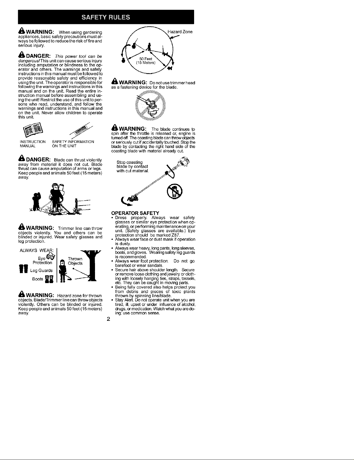
,_. DANGER: Blade can thrust violently
away from materia_ it does not cut. Blade
thrust can cause amputation of arms or legs.
Keep people andanimals 50 feet (15 meters)
away.
___td Zone
_WARNING: Do notuse trimmer heed
as afastening device for the blade.
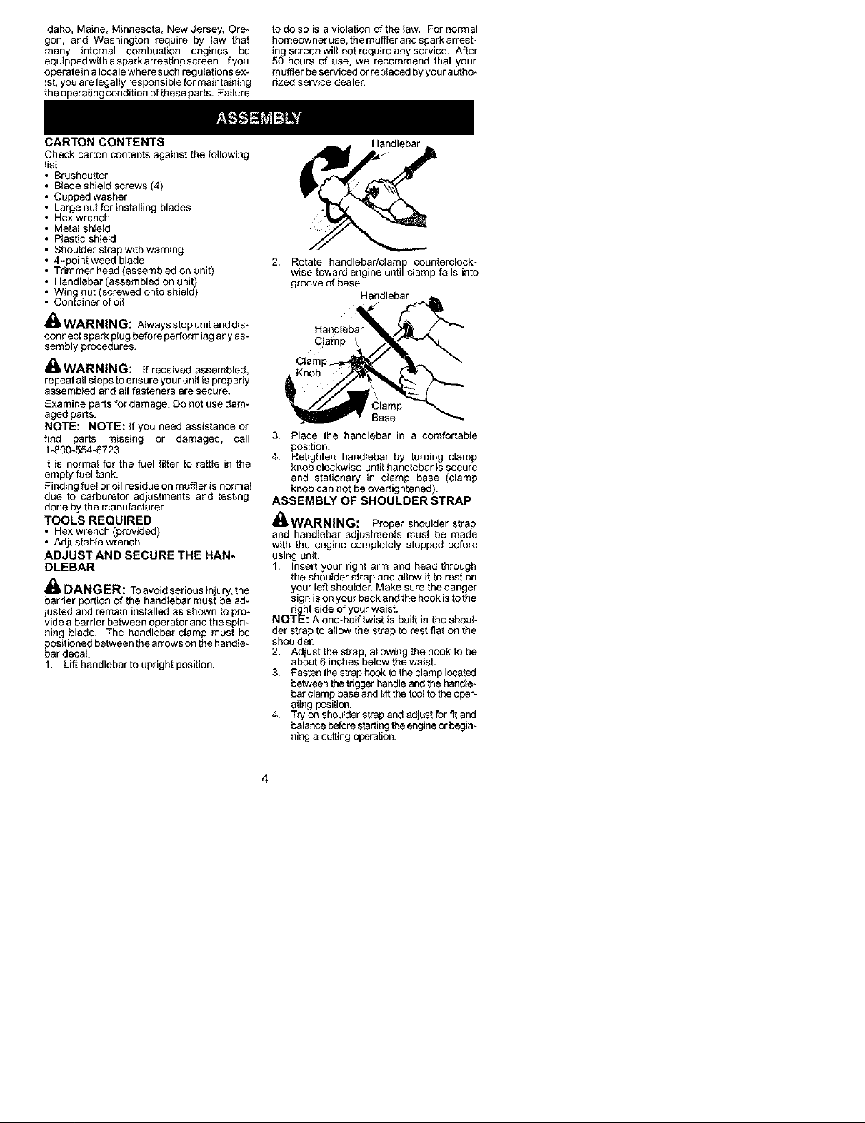
4==.WARNINL_: The blade continues to
spin after the throttle is released or, engine is
turnedoff.Thecoasting I_adecan throwobjects
or seriouslycut if accidentallytouched.Stop the
blade by contacting the right hand side of the
coasting bladewith material already cut.
Stop coasting
blade by contact
with cut material
®
13.WARNINL_: Trimmer line can throw
objects violently. You and others can be
blinded or in ured. Wear safety g_asses and
eg protect on.
ALWAYS WEAR:
Protection
I! LegGuards
Bootsl
_WARNING: Hazard zone for thrown
objects. Blade/Trimmer linecan throw objects
violently. Others can be blinded or injured.
Keep people andanimals 50 feet (15 meters)
away.
OPERATOR SAFETY
• Dress properly. Always wear safety
glasses or similar eye protection when op*
erating, or performing maintenance on your
unit. (Safety glasses are available.) Eye
protection should be marked Z87.
• Always wear face or dust mask ifoperation
is dusty.
• Always wear heavy, longpants,long sleeves,
boots,andgloves. Wearing safety ledguards
is recommended.
• A_wayswear foot protection. Do not go
barefoot or wear sandals.
• Secure hairabove shoulder length. Secure
or remove loose clothing andjewelry orcloth-
ing with loosely hanging ties, straps,tassels,
etc. Theycan becaught in moving parts.
• Being fully covered also helps protect you
from debris and pieces of toxic plants
thrown by spinning line/b_ade.
• Stay Aled. Do not operate unitwhen you are
tired, ill, upset or under influence of alcohol,
clrugs,or medication.Watchwhat youaredo*
Ing; use common sense.
2

• Wear hearing protection.
• Never start or run the engine inside a
closed room or building. Breathing exhaust
fumes can kill.
• Keep handles free of oil and foe[
• A{ways use the handlebar and a properly
adjusted shoulder strap with a b{ede (see
ASSEMBLY).
UNIT/MAINTENANCE SAFETY
_WARNING: Stop unit and disconnect
the spark plug before performing mainte-
nance (except carburetor adjustments).
• Look for and replace damaged or loose
parts before each use. Look for and repair
fuel leaks before use. Keep unit in good
working condition.
• Throw away blades that are bent, warped,
cracked, broken, ordamaged in any other
way. Replace trimmer head parts that are
cracked, chipped, broken, or damaged in
any other way before using the unit.
• Maintain unit according to recommended
procedures. Keep blade sharp. Keepcut_
ting line at the proper length.
• Use only 0.095" (2.4 mm) diameter Poulan
PRO® brand replacement line. Never use
wire, rope, string, etc.
• _nstallrequired shield properly before using
the unit. Use the metal shield for all metal
blade use. Use the plastic shield for all line
trimmer use.
• Useonly specified blade or trimmer head;
make sure it is properly inetaHed and se-
curely fastened.
• Never start engine with clutch shroud re-
moved. The clutch can fly offand cause se-
rious injury.
• Besure bledeor trimmer head stops turning
when engine idles.
• Make carburetor edjustmenta with the low-
er end supported to prevent blade or trim_
mer line from contacting any object. Hold
unit by hand;do not use the shoulder strap
for support.
• Keep others awaywhen making carburetor
adjustments.
• Use only recommended Poulan PRO®ac-
cessories and replacement parts.
• Have all maintenance and service not ex_
plainedin this manual performed byyour au-
thorized service dealer.
FUEL SAFETY
• Mix and pour fuel outdoors.
• Keep away from sparks or flames.
• Use a container approved for fuel.
• Donot smoke or allow smoking near foelor
the unit or whi_eusing the unit.
• Avoid spilling fuel or oil Wipe up all fuel
spills before starting engine.
• Move at least 10 feet (3 meters) away from
fueling site before starting engine.
• Stop engine and allow it to cool before re_
moving fuel cap.
• Empty the fueltank before storing ortrans-
porting the unit. Use upfuel left in the car-
buretor by starting the engine and letting it
run until it stops.
• Store unitand fuelin areawhere fuel vapors
cannot reach sparks or open flames from
water heaters, electric motors or switches,
furnaces, etc.
• Always store gasoline in a container ab-
proved for flammable liquids.
CUTTING SAFETY
_WARNING: Inspect the area to be
cut before each use. Remove objects (rocks,
broken glass, nails, wire, string, etc..)which
can be thrown or become entangled in the
blade or trimmer head.
• Keep others including children, animals,
bystanders, andhelpers at least 50 feet (15
meters) away. Stop engine immediately if
you are approached.
• Always keepengineontheright-handside
of your body.
• Hold the unit firmly with both hands.
• Keep firm footing and balance. Do not over-
reach.
• Keep blade or trimmer head below waist
level. Donot raise engine aboveyour waist.
• Keep all parts of your body away from
blade, trimmer head, and muffler when em
gineis running. Ahot mumercan causese-
rious burns.
• Cut from your left to your right. Cutting on
right side of the shield will throw debris
away from the operator.
: Use only in daylight orgood artificia_ light.
Use only for jobs explained in this manual.
TRANSPORTING AND STORAGE
• Stop the unit before carrying.
Keep muffler away from your body.
: Allow theengine tocoot andsecure the unit
before storing or transporting it in avehicle.
• Empty the fueltank before stedng or trans-
porting the unit. Use upfuel leftin thecarbu*
retor bystarting the engine and letting it run
until it stops.
• Store unit so the blade or line limiter blade
cannot accidentally cause injury. The unit
can be hung bythe tube.
• Store unit out of reach of children.
SAFETY NOTICE: Exposure to vibrations
through prolonged use of gasoline powered
handtools could cause blood vessel or nerve
damage in the fingers, hands, and joints of
people prone to circulation disorders or ab-
normal swellings. Prolonged use in cold
weather has been linked to blood vessel dam-
agein otherwise healthy people, ffsymptoms
occur such as numbness, pain, loss of
strength, change in skin color or texture, or
loss of feeling in the fingers, hands, or joints,
discontinue the use ofthis toot and seek med-
ical attention. An anti-vibration system does
not guarantee the avoidance of these prob-
lems. Users who operate power tools on a
continual and regular basis must monitor
closely their physical condition and the condi-
tion of this tool.
SPECIAL NOTICE: This unit is equipped
with a temperature limiting muffler and spark
arresting screen which meets the require-
ments of California Codes 4442 and 4443. All
U.S. forest land and the states of California,
3
Idaho, Maine, Minnesota, New Jersey, Ore-
gon, and Washington require by law that
many internal combustion engines be
equippedwith aspark arresting screen. Ifyou
operatein a locale where such regulations ex-
ist, you are legally responsible for maintaining
the operating condition of these parts. Failure
to do so is a violation of the law. For normal
homeowner use,the mumerand spark arrest-
ing screen will not require any service. After
50 hours of use, we recommend that your
muff]erbeserviced or replaced byyour autho_
dzed service dealer.
CARTON CONTENTS
Check carton contents against the following
list:
Brushcutter
Blade shield screws (4)
Cupped washer
Large nut for installing blades
Hex wrench
Metal shield
Plastic shield
Shoulder strap with warning
4-point weed blade
Trimmer head (assembled on unit)
Handlebar (assembled on unit)
Wing nut (screwed onto shield)
Container of oil
_WARNING: Always stop unit and dis-
connect spark plugbefore performing any as-
sembly procedures.
,_.WARNING: If received assembled,
repeat allsteps to ensure your unit is propedy
assembled and atlfasteners are secure.
Examine partsfor damage. Do not usedamn
aged parts.
NOTE: NOTE: If you need assistance or
find parts missing or damaged, call
1-800-554-6723.
It is normal for the fuel filter to ratbo in the
empty fuel tank.
Finding fuel or oil residue on muffler is norm al
due to carburetor adjustments and testing
done by the manufacturer
TOOLS REQUIRED
• Hexwrench (provided)
• Adjustable w_ench
ADJUST AND SECURE THE HAN-
DLEBAR
_ DANGER: Toavoid serious inury, the
herr er port on of the hand ebar must be ad_
justedand remain installed as shown to pro-
vide a barrier between operator and the spire
ning blade. The handlebar clamp must be
positioned between the arrows on the handle-
bar decal
1. Lift handlebar to upright position.
Handlebar
2. Rotate handlebar/clamp counterclock-
wise toward engine until clamp falls into
groove of base.
Clamp
Clam
3. Place the handlebar in a comfortable
position.
4. Retighten handlebar by turning clamp
knob clockwise until handlebar is secure
and stationary in clamp base (clamp
knob can not be overtightened).
ASSEMBLY OF SHOULDER STRAP
_WARNING: Proper shoulder strap
and handlebar adjustments must be made
with the engine completely stopped before
using unit.
1. Insert your right arm and head through
the shoulder strap and allow itto rest on
your left shoulder. Make sure the danger
sign is on your back andthe hook is tothe
d_ht side of your waist.
NOTE: A one-haff twist is built in the shoul-
der strap to allow the strap to rest flat on the
shoulder.
2. Ad ust the strap, allowing the hook to be
about 6 nches be ow the wa st.
3. Fastenthestrap hook to the clamp located
between the triggerhandleandthe handle-
her clamp baseand lif_the tootto theoper-
ating position.
4. Try on shoulderstrap and adjustfor fit and
balance before sfedingtheengineor begim
ning a cuttingoperation.
Handlebar
Base
4
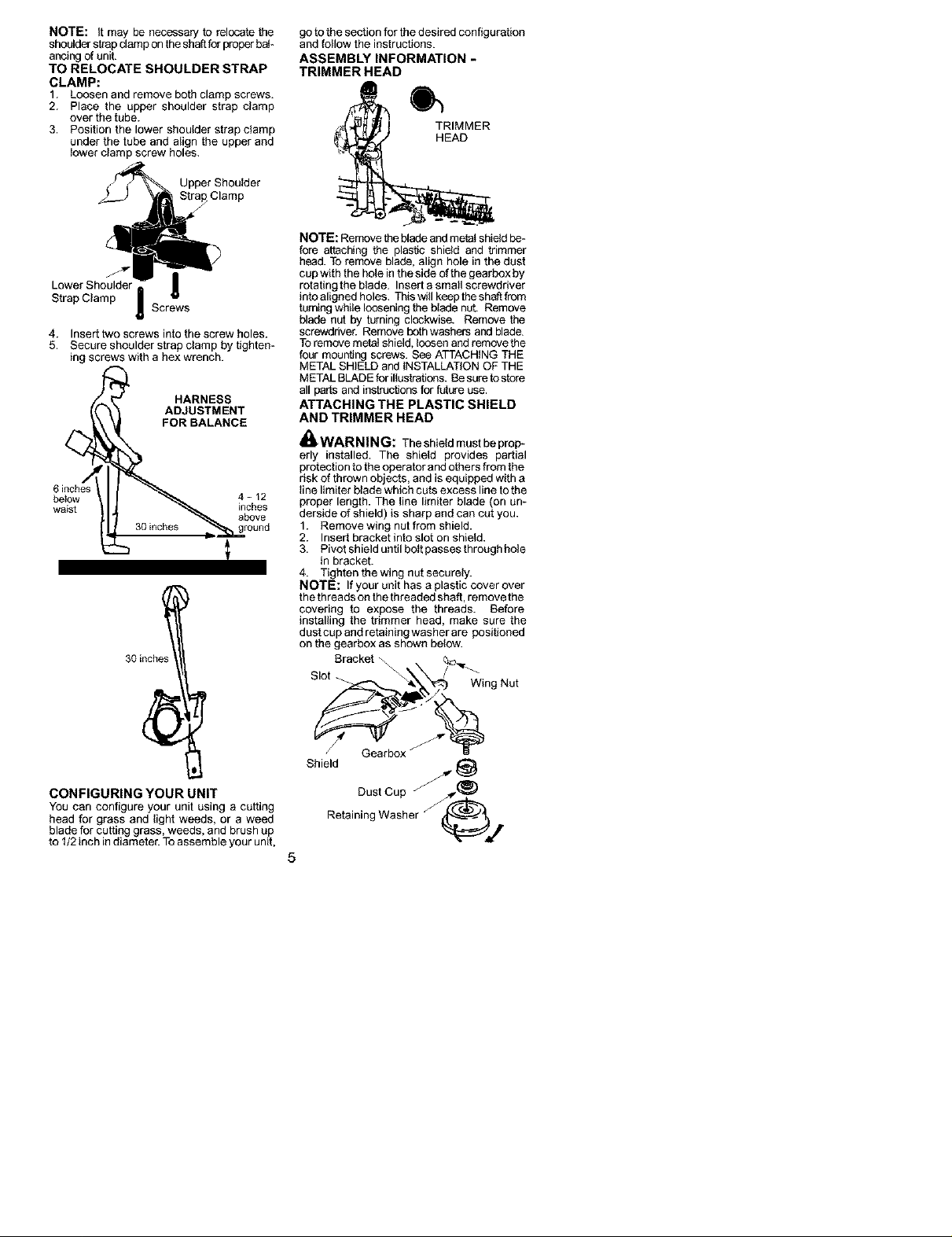
NOTE: it may be necessary to relocate the
shoulderstrapclamp onthe shaftforproperbah
ancingof unit.
TO RELOCATE SHOULDER STRAP
CLAMP:
1. Loosen and remove both clamp screws.
2. Place the upper shoulder strap clamp
over the tube.
3. Position the lower shoulder strap clamp
under the tube and a_ignthe upper and
_owerclamp screw holes.
Upper Shoulder
Clamp
Lower Shoulder J
Strap Clamp
4. Insert two screws into the screw holes.
5. Secure shoulder strap clamp by tighten-
ing screws with a hex wrench.
6 inches
betow 4 - 12
waist inches
Screws
30inches
HARNESS
ADJUSTMENT
FOR BALANCE
.'_ ground
above
goto the section for thedesired configuration
and follow the instructions.
ASSEMBLY INFORMATION -
TRIMMER HEAD
TRIMMER
HEAD
NOTE: Remove theblade andmeta_shieldbe-
fore attaching the plastic shield and trimmer
head. To remove blade, align hole inthe dust
cup with the hole in the side ofthe gearbox by
rotating the blade. Insert asmall screwdriver
into aligned holes. This will keeptheshaftfrom
turningwhile looseningtheb_adenut. Remove
blade nut by turning clockwise. Remove the
screwdriver. Remove both washers and blade.
Toremove meta_shield,loosenand remove the
four mounting screws. Bee ATTACHING THE
METAL SHIELD and INSTALLATIONOF THE
METALBLADE for illustrations.Besure tostore
all pade andinstructions for future use.
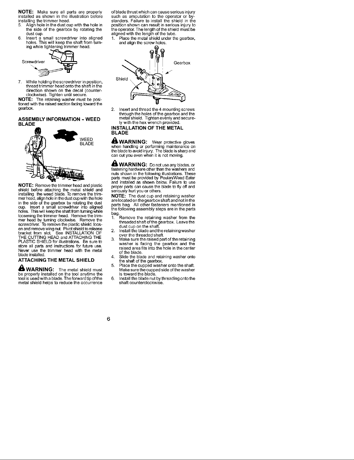
ATTACHING THE PLASTIC SHIELD
AND TRIMMER HEAD
_WARNING: The shield must be prop*
erly installed. The shield provides partial
protectionto the operator and others from the
risk of thrown objects, and is equipped witha
_inelimiter blade which cuts excess line to the
proper length. The line limder blade (on un-
derside of shield) is sharp and can cut you.
1. Remove wing nut from shield.
2. Insert bracket into slot on shield.
3. Pivot shield unfil bo_tpassesthrough hole
in bracket.
4. Tighten the wing nut securely.
NOTE: If your unit has a plasticcover over
thethreads onthe threaded shaft, remove the
covering to expose the threads. Before
installing the trimmer head, make sure the
dust cup and retaining washer are positioned
on the gearbox as shown below.
Bracket -_\_
Slot
Wing.or
CONFIGURING YOUR UNIT
You can configure your unit using a cutting
head for grass and light weeds, or a weed
blade for cutting grass, weeds, and brush up
to I/2 inch indiameter. Toassemble your unit,
Shield
Dust Cup @___
Retaining Washer @4€_
5
NOTE: Make sure al; parts are properly
fastaltad as shown in the illustration before
installing the trimmer head.
5. Align hole in thedust cup with the hole in
the side of the gearbox by rotating the
dust cup.
6. Insert a smal; screwdriver into aligned
holes. This wil_keep the shaftfrom turn_
fag whi;e tightening trimmer head.
of bladethrust which can causeserious injury
such as amputation to the operator or by-
standers. Failure to install the shield in the
position shown can result inserious injury to
theoperator. The length of theshield must be
aligned with the length of the tube.
1. Place the metal shield under the gearbox,
and align thescrew holes.
Screwdriver
7. While holding thescrewdriver in position,
thread trimmer head onto the shaft in the
direction shown on the decal (counter_
clockwise). Tighten until secure.
NOTE: The retaining washer must be pobl-
tioned with the raised section facing toward the
gearbox.
ASSEMBLY INFORMATION - WEED
BLADE
_WEED
BLADE
NOTE: Removethe trimmer headand plastic
shield before attaching the metel shield and
installing the weed blade. To remove the tdm-
methead, alignhole inthedustcupwith thehele
in the side of the gearbox by rotating the dust
cup. Insert a small screwdriver into aligned
holes. Thiswill keepthe shaft fiom turningwhile
faoseningthe thmmer head. Remove the tdm-
met heed by turning clockwise. Remove the
screwdriver. Toremove theplastic shield, loos-
enand removewing nut. Pivot shieldto release
bracket from slot. See INSTALLATION OF
THE CU3RING HEAD and ATTACHING THE
PLASTIC SHIELD for iiluelrations. 8e sure to
store all parts and instructionsfor future use.
Never use the trimmer head with the metal
blade installed.
ATTACHING THE METAL SHIELD
_WARNING: The metal shield must
be properly installed on the tool anytime the
tool is used with a blade. Theforward tip of the
metal shield helps to reduce the occurrence
Gearbox
Shield
2. Insert and thread the 4 mounting screws
through the holes ofthe gearbox and the
metal shield. Tighten evenly and secure-
ly with the hex wrench provided.
INSTALLATION OF THE METAL
BLADE
_WARNING: Wear protective gloves
when handling or performing maintenance on
thebladetoavoid injury. The bladeissharpand
can cut you even when it is not moving.
_WARNING: Do notuse any blades,or
fasteninghardware other than thewashers and
nuts shown inthe fc_lowingillustrations. These
parts must be providedby PoulanNVeedEater
and installed as shown below. Faiture to use
proper partscan cause the bladeto fly off and
seriously hurt you or others.
NOTE: The dust cup and retaining washer
arelocated on thegearbox shaft andnot inthe
parts bag. All other fasteners mentioned in
thefollowing assembly steps are in the parts
bag.
1. Remove the retaining washer from the
threaded shaftof the gearbox. Leave the
dust cup on the shaft.
2. Install the blade and the retaining washer
over the threaded shaft.
3. Make sure theraised part of theretafafag
washer is facing the gearbox and the
raised area fits into the hole in the center
of the blade.
4. Slide the blade and retainingwasher onto
the shaft of the gearbox.
5. Place the cupped washer onto the shaft.
Make surethe cupped side of the washer
is toward the blade.
6. Install the blade not by threadfag ontothe
shaft counterblockwise.
6
Shield
Gearbox
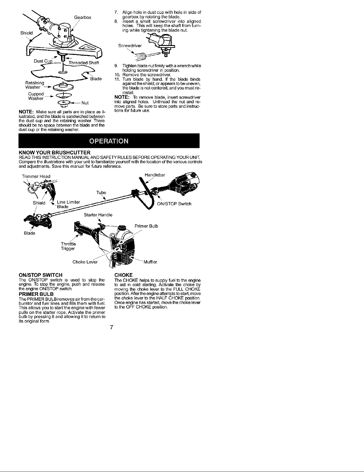
7. Align hole in dust cup with hole in side of
gearbox by rotating the blade.
8. Insert a small screwdriver into aligned
holes. This will keep the shaft from turn-
ing while tightening the blade nut.
Screwdriver
Threaded Shaft
Retaining
Washer _ _
Cupped
Washer
_Nut
NOTE: Make sure all parts are in piece as iF
lustrated, and the blade is sandwiched between
the dust cup and the retaining washer. There
should he no space between the blade and the
dust cup or the retaining washer.
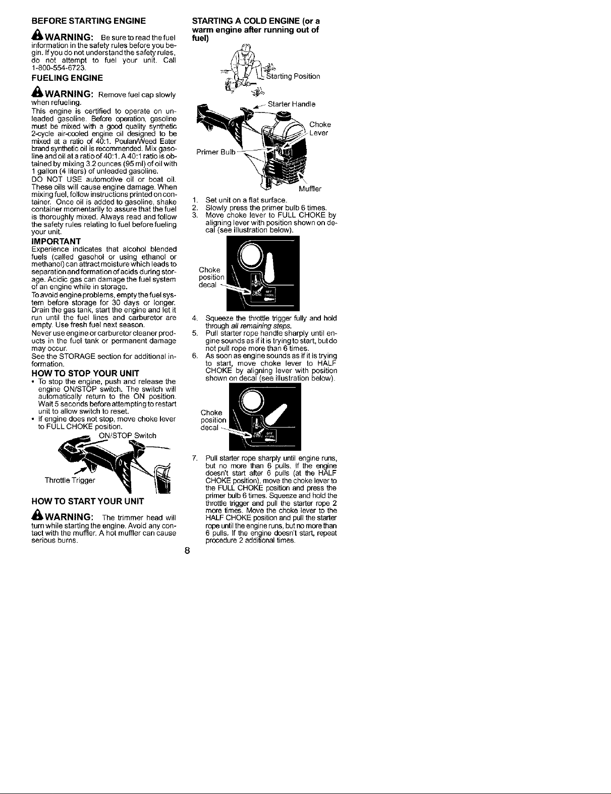
KNOW YOUR BRUSHCUTTER
READ THIS INSTRUCTIONMANUAL AND SAFETYRULES BEFOREOPERATING YOUR UNR_
Comparethe illustrations with your unit tofamiliarize yourself with thelocation ofthe vaheus controls
and adjustments. Save this manual for future reference.
Blade
Trimmer Head
_ N_k_Liln_Limite r
Starter Handle
9. Tllgrhtenbledenutfirmlywithawrenchwhile
holding screwdriver in _ition.
10. Remove the screwdriver.
]t. Turn blade by hand. If the blade binds
againstthe shield, or appears to be uneven,
the blade is not centered, and you must re_
install.
NOTE: To remove blade, insert screwdriver
into aligned holes. Unthread the nut and re*
move parts. Be sure to store parts and instruc-
tions for future use.
Handlebar
ON/STOP Switch
Primer Bulb
Throttle
Trigger
Choke Lever
ON/STOP SWITCH
The ON/STOP switch is used to stop the
engine. To stop the engine, push and release
the engine ON/STOP switch.
PRIMER BULB
The PRIMER BULB removes air from thecar*
buretor and fuel lines and fills them with fuel.
This allows you to start the engine with fewer
pulls on the starter rope. Activate the primer
bulb by pressing it and allowing it to return to
its original form.
CHOKE
The CHOKE helps to supply fuetto the engine
to aid in cold starting. Activate the choke by
moving the choke lever to the FULL CHOKE
position.Aftertheengineattemptsto start,move
thechoke lever to the HALF CHOKE position.
Onceengine has started,movethe choke lever
to the OFF CHOKE position.
7
BEFORE STARTING ENGINE
_WARNING: Besure to read the fuel
information in the safety rules before you be-
gin. Ifyou do not understand the safety rules,
do not attempt to fuel your unit. Call
1-800_554-6723.
FUELING ENGINE
_WARNING: Remove fuel cap slowly
when refueling.
This engine is certified to operate on um
leaded gasoline. Befc_e operation, gasoline
must be mixed with a good quality synthetic
2*cycle air-cooled engine oil designed to be
mixed at a ratio of 40:1. PoulanANeedEater
brandsyntheticoil is recommended. Mixgasc_
line and oil ata ratio of 40:1.A 40:1ratio is ob_
tained by mixing 3.2ounces (95 ml) of oil with
1 gallon (4 liters) of unleaded gasoline.
DO NOT USE automotive oil or boat oil.
These oils will cause engine damage. When
mixing fuel, follow instructionsprintedon con_
tainer. Once oil is added to gasoline, shake
container momentarily to assure that the fuel
is thoroughly mixed. Always read andfollow
the safety rules relating to fuel before fueting
your unit.
IMPORTANT
Experience indicates that alcohol blended
fuels (called gasohol or using ethanol or
methanol) can attract moisture which leadsto
separation and formation of acids during stor-
age.Acidic gas can damage the fuel system
of an engine while in storage.
Toavoid engine problems, empty thefuel sys*
tern before storage for 30 days or longer.
Drain the gas tank, start the engine and let it
run until the fuel lines and carburetor are
empty. Use fresh fuel next season.
Never use engine or carburetor cleaner prod-
ucts in the fuel tank or permanent damage
may occur.
See the STORAGE section for additional im
formation.
HOW TO STOP YOUR UNIT
• To stop the engine, push and release the
engine ON/STOP switch. The switch will
automatically return to the ON position.
Wait 5seconds before attempting torestart
unit to allow switch to reset.
• Ifengine does not stop, move choke lever
to FULL CHOKE position.
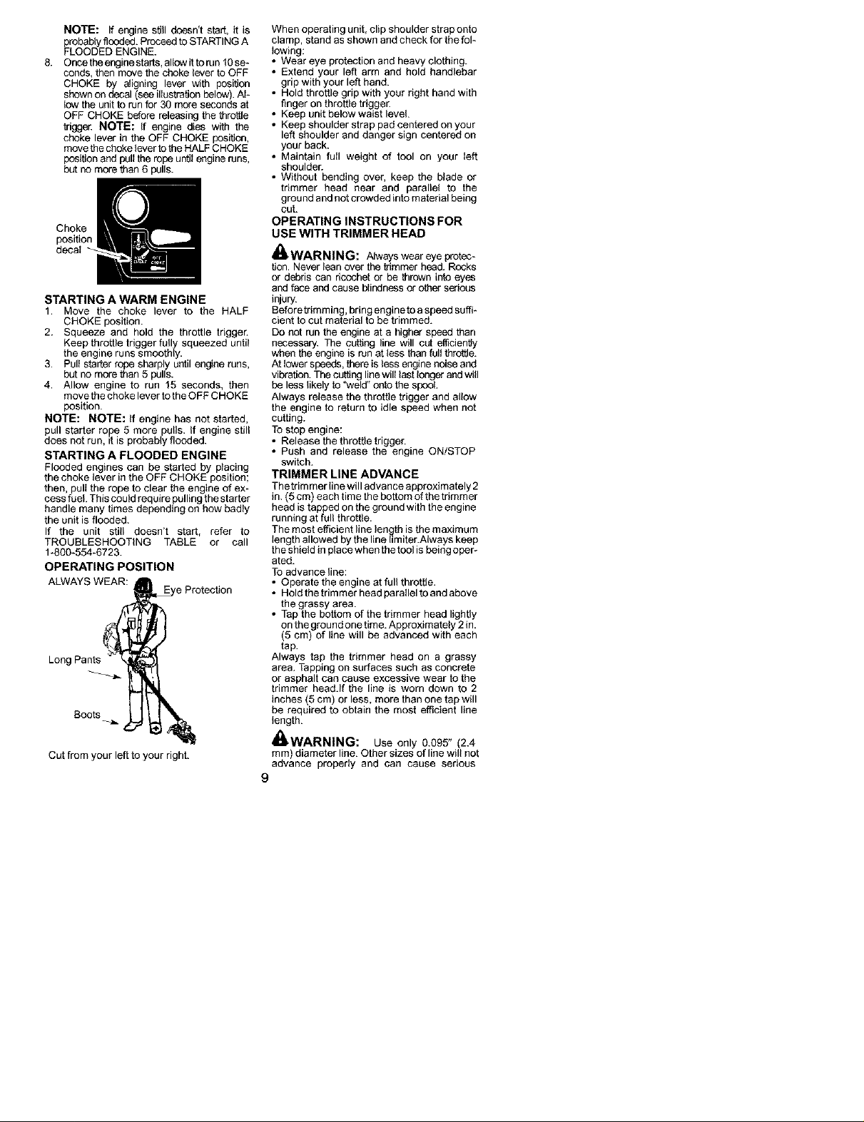
STARTING A COLD ENGINE (or a
warm engine after running out of
fuel)
rting Position
J Starter Handle
Choke
-Lever
Primer Bulb
Muffler
1. Set unit on a flat surface.
2. Slowly press the primer bulb 6 times.
3. Move choke lever to FULL CHOKE by
ali ning lever with position shown on de_
ca_(see illustration below).
Choke
position
decal
4. Squeeze the throffle tnggorfully and hold
throughall remaining stega.
5. Pull starter rope handle sharply until en-
gine sounds as if itis trying to start, butdo
not pull rope more than 6 times.
6. As soon as engine sounds as ifit is trying
to start, move choke lever to HALF
CHOKE by aligning lever with position
shown on decal (see illustration below).
Thrott'oT"0 11
HOW TO START YOUR UNIT
_WARNING: The trimmer head will
turn while starfin_gthe engine. Avoid any con-
tact with the muffler. A hot muffler can cause
serious burns.
Pull startar rope sharply until engine runs,
but no more than 6 pulls. If the engline
dcesn't start after 6 pulls (at the HALF
CHOKE position), move thechoke leverto
the FULL CHOKE position and press the
pdmer bulb 6times.Squeeze and hold the
throttle tdggor and pull the starter rope 2
more times. Move the choke lever to the
HALF CHOKE positionand pullthe starter
rope untilthe engine runs,butno morethan
6 pulls. If the engine doesn't start, repeat
prccedure 2 additionaltimes.
8
NOTE: If engine still doesn't star{, it is
probablyflooded.ProceedtoSTARTINGA
FLOODED ENGINE.
8. Once tbeenginestaffs, al;owit torun 10se-
coeds,then move the choke lever to OFF
CHOKE by a_igning lever with position
shown ondecal (see illustration below).A_-
low the unit to runfor 30 more seconds at
OFF CHOKE before releasingthe throttle
trigger. NOTE: If engine dies with the
choke lever in the OFF CHOKE position,
move thechoke lever to the HALFCHOKE
position andpull therope untilengineruns,
but no morethan 6 pulls.
STARTING A WARM ENGINE
1. Move the choke lever to the HALF
CHOKE position.
2. Squeeze and hold the throttle trigger.
Keep throttle trigger fully squeezed until
the engine runs smoothly.
3. Pul; starter rope sharply until engine runs,
but no morethan 5 pulls.
4. Allow engine to run 15 seconds, then
move thechoke lever to theOFF CHOKE
position.
NOTE: NOTE: ff engine has not started,
pull starter rope 5 more pulls. If engine still
does not run, it is probably flooded.
STARTING A FLOODED ENGINE
Flooded engines can be started by placing
the choke lever in the OFF CHOKE position;
then, pull the rope to clear the engine of ex-
cess fuel. This could require pulling the starter
handle many times depending on how badly
the unit is flooded.
If the unit still doesn't start, refer to
TROUBLESHOOTING TABLE or call
1-800-554-6723.
OPERATING POSITION
ALWAYS WEAR:
Long Pants
e Protection
Boots
Cut from your left to your right.
When operating unit, clip shoulder straponto
clamp, stand as shown and check for the fol_
lowing:
• Wear eye protection and heavy clothing.
• Extend your left arm and hold handlebar
grip with your left hand.
• Hold throttle grip with your right hand with
finger on throttle trigger.
• Keep unit below waist level
• Keep shoulder strap pad centered on your
left shoulder and danger sign centered on
your back.
• Maintain full weight of tool on your left
shoulder.
• Without bending over, keep the blade or
trimmer head near and parallel to the
ground and not crowded into material being
cut.
OPERATING INSTRUCTIONS FOR
USE WITH TRIMMER HEAD
_WARNING: Always wear eye protec_
t_on.Never lean over the trimmer head. Rocks
or debris can ncochetor be thrown into eyes
andface and cause blindnessor o_er serious
injury.
Beforetrimming, bring engineto aspeed suffi-
cient to cutmaterial to betrimmed.
Do not run the engine at a higher speed than
necessary. The cutting line will cut efficiently
when the engine is run at less than ful_throttle.
At_owerspeeds,thereis lessenginenoise and
vibration.The cuttinglinewil_lastlonger andwill
be less likely to 'weld" ontothe spocL
Always release the throttle trigger and allow
the engine to return to idle speed when not
cutting.
TOstop engine:
Release the throttle trigger.
Push and release the engine ON/STOP
switch.
TRIMMER LINE ADVANCE
Thetrimmer line will advance approximately 2
in. (5 cm) each time the bottom ofthe trimmer
head is tapped on the ground with the engine
running at full throttle.
Themost efficient linelen,._thisthemaximum,
_engthallowed by the line hm,ter.Always keep
theshield in p_acewhen thetoef is being oper-
ated.
To advance line:
• Operate the engine at full throffie.
• Hold the trimmer head poraHelto andabove
the grassy area.
• Tap the bottom of the trimmer head lightly
on the ground onetime. Approximately 2 in.
(5 cm) of line will be advanced with each
tap.
Always tap the trimmer head on a grassy
area. Tapping on surfaces such asconcrete
or asphalt can cause excessive wear tothe
trimmer head.If the line is worn down to 2
inches (5 cm) or less, more than one tap will
be required to obtain the most efficient line
_ength.
_WARNING: Use only 0.095" (2.4
mm) diameter line. Other sizes of line will not
advance properly and can cause serious
9
injury.DOnotuseothermaterialssuchas
wire,atdng,rope,etc.Wirecanbreakoffdur*
ingcuttingandbecomeadangerousmissile
thatcancauseseriousinjury.
CUTTING METHODS
_WARNINL_: Use minimum speed
anddo notcrowd the linewhen cutting around
hard objects (rock, gravel, fence posts, etc.),
which candamage the trimmer head, become
entangled in the line, or bethrown causing a
serious hazard.
• The tip of the line does the cutting. You will
achieve the best performance and minim
mum line wear by not crowding the line into
the cutting area. The right andwrong ways
are shown below.
• The line will easily remove grass and
weeds fromaround wails, fences, trees and
flower beds, but it also can cut the tender
bark of trees or shrubs and scar fences.
• Fortrimming or scalping, use less thanfull
throttle to increase line life and decrease
head wear, especially:
• During light duty cutting.
Near objects around which the line can
wrap such as small posts, trees or fence
wire.
• Formowing or sweeping, usefull throtfle for
a good clean job.
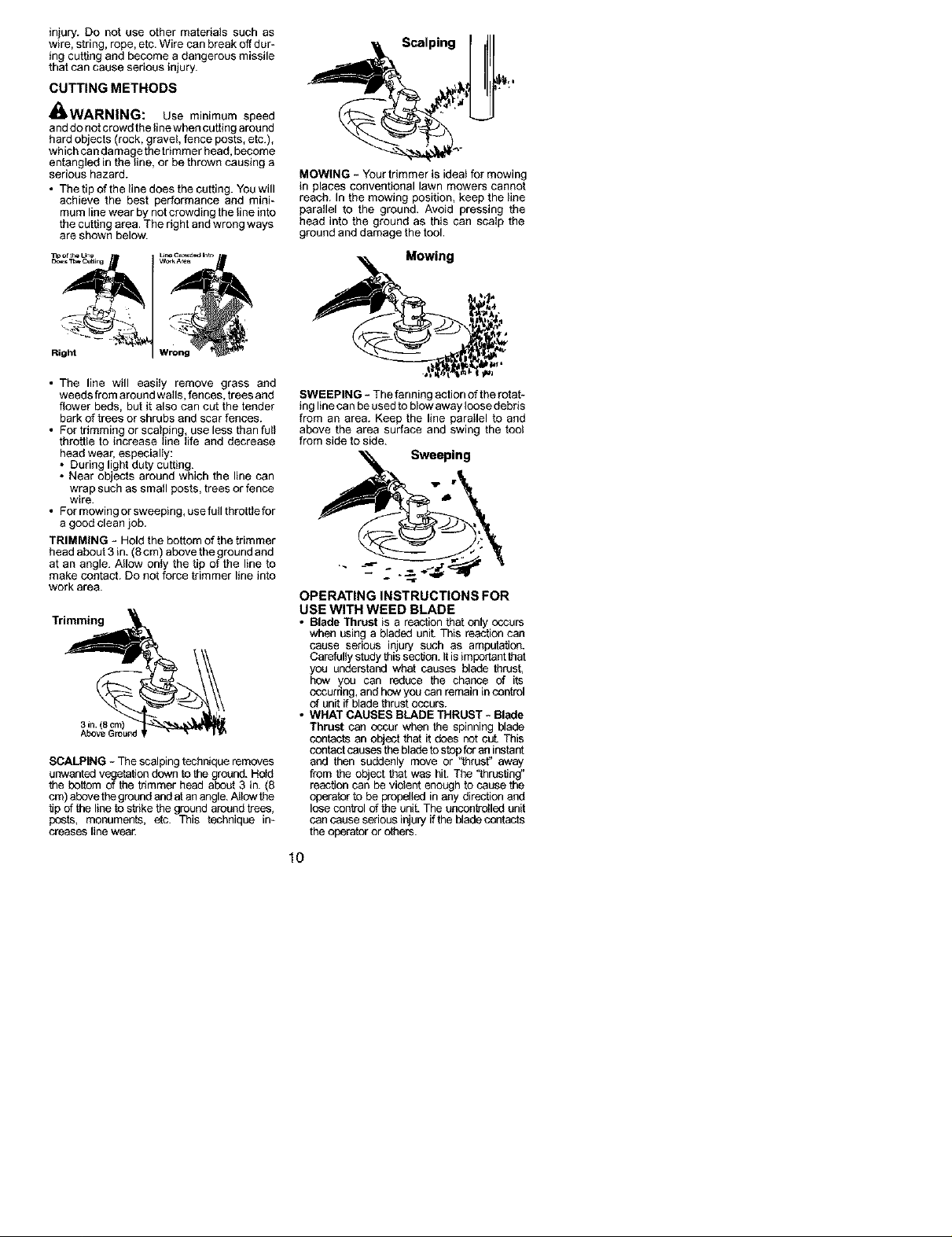
TRIMMING - Hold the bottomof the trimmer
headabout 3 in. (8 cm) above theground and
at an angle. Allow only the tip of the line to
make contact. Do notforce trimmer line into
work area.
Trimming
3in. (8 cm)
AboveGround
SCALPING - The scalpingtechnique removes
unwanted vesgetationdown tothegrcound.Hold
the bottom o_the trimmer head about3 in. 8
cm abovethegroundand atanang e. Ai owthe
tjp of the line to strike the ground aroundtrees,
posts, monuments, etc. This technique in-
creases line wear.
Scalping
MOWING - Your trimmer is ideat for mowing
in places conventional lawn mowers cannot
reach. In the mowing position, keep the line
parallel to the ground. Avoid pressing the
head into the ground as this can scalp the
ground and damage the tool.
Mowing
SWEEPING - The fanning action ofthe rotat-
ing line ca n be usedto blow away loosedebris
from an area. Keep the line parallel to and
above the area surface and swing the toat
from side to side.
Sweeping
OPERATING INSTRUCTIONS FOR
USE WITH WEED BLADE
• Blade Thrust is a reactionthatonly occurs
when using a bladed unit. This reaction can
cause serious injury such as amputation.
Carefullystudy this section.Itis importantthat
you understand what causes blade thrust,
hew you can reduce the chance of its
occurring,and howyou can remain incontrol
of unit if blade thrustoccurs.
• WHAT CAUSES BLADE THRUST - Blade
Thrust can occur when the spinning blade
contacts an object that it does not cut. This
contactcauses the bladetostopforan instant
and then suddenly move or "thrust" away
from the object that was hit. The "thrusting"
reaction can be violent enough to cause the
operator to be propelled in any directionand
losecontrol of the unit.The uncontrolledunit
can cause serious injury ifthe bladecontacts
the operatoror others.
10
 Loading...