

Poulan Pro 279910 PR18542STA, 279910 Owner's Manual
IMPORTANT MANUAL Do Not Throw Away
Poulan
OWNER'S MANUAL
MODEL:
PR18542STA
WARNING :
Read the Owner's Manual and follow
all Warnings and Safety Instructions.
Failure to do so can result in serious
injury.
LAWNTRACTOR
279910 PR18542STA
Always Wear Eye Protection During Operation
174397 2.16.00 JH
Printed in U.S.A.

& SAFETY RULES
A
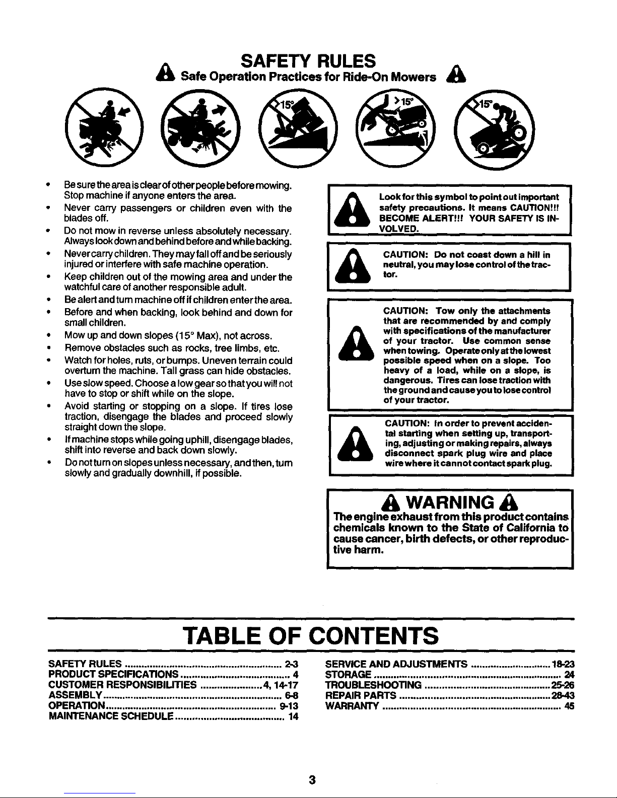
Safe Operation Practices for Ride-On Mowers
IMPORTANT: THIS CUTTING MACHINE IS CAPABLE OF AMPUTATING HANDS AND FEET AND THROWING OBJECTS.
FAILURE TO OBSERVE THE FOLLOWING SAFETY INSTRUCTIONS COULD RESULT IN SERIOUS INJURY OR DEATH.
I. GENERAL OPERATION
• Read, understand, and follow all instructions in the
manual and on the machine before starting.
• Onlyallow responsible adults, who are familiarwith the
instructions,to operate the machine.
• Clear thearea ofobjects such as rocks,toys, wire,etc.,
whichcould be picked UPand thrown by the blade.
• Besurethe area isclear of other people before mowing.
Stop machine ifanyone enters the area.
• Never carrypassengers.
• Do not mow in reverse unless absolutely necessary.
Alwayslookdownand behind before and while backing.
• Be aware of the mower discharge direction and do not
point it at anyone. Do not operate the mower without
either the entire grass catcher or the guard in place.
• Slow downbefors turning.
• Never leavea running machine unattended. Alwaystum
Offblades, set parking brake, stop engine, and remove
keys before dismounting.
• Turn offblades when notmowing.
• Stop engine before removing grass catcher or unclog-
gingchute.
• Mow only in daylight or good artificial light.
• Do notoperate the machine while underthe influenceof
alcoholor drugs.
• Watch for trafficwhen operating near or crossingroad-
ways.
• Use extra care when loading or unloading the machine
intoa trailer or truck.
• Data indicates that operators, age 60 years and above,
are involved in a large percentage of riding mower-
related injuries. These operators shouldevaluate their
ability to operate the riding mower safely enough to
protectthemselves and others from serious injury.
II. SLOPE OPERATION
Slopes are a major factor related to loss-of-control and
tipover accidents,whichcan rssult insevere injuryordeath..
All slopes require extra cauUon. If you cannot back up the
slope or if youfeel uneasy on it, do notmow it.
DO:
• Mow up and down slopes, not across.
• Remove obstacles such as rocks, tree limbs, etc.
• Watch for holes, ruts,or bumps. Uneven terrain could
overturnthe machine. Tafl grass can hide obstacles.
• Use slow speed. Choose a low gear so that youwill not
have to stop or shiftwhile on the slope.
• Followthe manufacturer's recommendations forwheel
weights or counterweights to improve stability.
• Use extra care with grass catchers or other attach-
ments. These can change the stability ofthe machine.
• Keep allmovement on the slopes slowand gradual Do
not make sudden changes in speed ordirection.
• Avoid starting or stopping on a slope. If tires lose
traction, disengage the blades and proceed slowly
straight down the slope.
2
DO NOT:
• Do not turn onslopes unless necessary, andthen, tum
slowly and gradually downhill, ifpossible.
• Do not mow near drop-offs,ditches, or embankments.
The mowercould suddenlytum overifawheel isoverthe
edge of a cliff or ditch, or if an edge caves in.
• Donotmowonwetgrass.Reducedtractioncouldcause
sliding.
• Do not tryto stabilize the machine by puttingyourfoot
onthe ground.
• Do not use grass catcher onsteep slopes.
III. CHILDREN
Tragic accidents can occur ifthe operator isnotalertto the
presence of children. Children are often attracted to the
machine and the mowing activity. Never assume that
children will remain where you last saw them.
• Keep children out of the mowing area and under the
watchful care of another responsibleadult.
• Be alert and tum machine offifchildren enter the area.
• Before and when backing, look behind and down for
small children.
• Never carry childrsn. They may fall offand be seriously
injured or interfere with safe machine operation.
• Never allow children tooperate the machine.
• Use extracare when approachingblindcomers, shrubs,
trees, or other objects that may obscure vision.
IV. SERVICE
• Use extra care in handling gasoline and other fuels.
They are flammable and vapors are explosive.
Use only an approved container.
Never remove gas cab or add fuel with the engine
running. Allow engine tocool before refueling. Do
not smoke.
Never refuel the machine indoors.
Never store the machine or fuel container inside
where there isan open flame, suchasawater heater.
• Never run a machine inside a closed area.
• Keep nuts and bolts,especially blade attachment bolts,
tight and keep equipment in good condition.
• Never tamper with safety devices. Check their proper
opera'don regularly.
• Keep machine free of grass, leaves, or other debris
buUd-up.Clean oilorfuelspillage. Allowmachine tocool
before storing.
• Stop and inspect the equipment ifyou strikean object.
Repair, ifnecessary, before restarting.
• Never make adjustments or repairs with the engine
running.
• Grass catcher components are subject to wear, dam-
age, and deterioration,whichcouldexpose movingparts
orallow objectsto bethrown. Frequently checkcompo-
nents and replace with manufacturer's recommended
parts, when necessary.
• Mower blades are sharp andcancut. Wrepthe blade(s)
or wear gloves, and use extra caution when servicing
them.
• Check brake operation frequently. Adjustand service
as required.
SAFETY RULES
A Safe Operation Practices for Ride-On Mowers _lb
• Besum theareaisclear ofotherpeople before mowing.
Stop machine if anyone enters the area.
• Never carry passengers or children even with the
blades off.
• Do not mow inreverse unless absolutely necessary.
Alwayslookdownandbehind before andwhile backing.
• Never carrychUdren.They may falloffand besedously
injured orinterfere with safe machine operation.
• Keep children out of the mowing area and under the
watchfulcare of another responsible adult.
• Bealert and turnmachine off ifchildren enter the area.
• Before and when backing, look behind and down for
small children,
• Mow up and down slopes (15 ° Max), not across.
• Remove obstacles such as rocks, tree limbs, etc.
• Watch for holes, ruts, or bumps. Uneven terrain could
overturnthe machine. Tall grass can hide obstacles.
• Useslow speed. Choose a low gear sothat you wiltnot
have to stopor shift while on the slope.
• Avoid starting or stopping on a slope. If tires lose
traction, disengage the blades and proceed slowly
straightdown the slope.
• Ifmachine stopswhilegoing uphill, disengage blades,
shift intoreverse and back down slowly.
• Do nottum onslopesunless necessary, and then, turn
slowlyand gradually downhill, if possible.
Look for this symbol to point out important
safety precautions. It means CAUTION!!!
BECOME ALERT!!! YOUR SAFETY IS IN-
VOLVED.
CAUTION: Do not coast down a hill in
neutral, you may lose control of the trac-
tor.
A
CAUTION: Tow only the attachments
that are recommended by and comply
with specifications of the manufacturer
of your tractor. Use common sense
when towing. Operete only at the lowest
possible speed when on a slope. Too
heavy of a load, while on a slope, is
dangerous. Tires can lose traction with
the ground and cause you to lose control
of your tractor.
A
CAUTION: In order to prevent acciden-
tal starting when setting up, transport-
ing, adjusting or making repairs, always
disconnect spark plug wire and place
wirewhere itcannot €ontsct spark plug.
a WARNING A
The engine exhaust from this product contains
chemicals known to the State of California to
cause cancer, birth defects, or other reproduc-
tive harm.
TABLE OF CONTENTS
SAFETY RULES ........................................................ 2-3
PRODUCT SPECIFICATIONS ....................................... 4
CUSTOMER RESPONSIBILITIES ...................... 4, 14-17
ASSEMBLY ................................................................ 6-8
OPERATION ............................................................. 9-13
MAINTENANCE SCHEDULE ....................................... 14
SERVICE AND ADJUSTMENTS ............................. 18-23
STORAGE ................................................................... 24
TROUBLESHOOTING ............................................. 25-26
REPAIR PARTS ...................................................... 28.43
WARRANTY ................................................................ 45
3

PRODUCT SPECIFICATIONS
GASOLINECAPACITY 2.00 GALLONS
ANDTYPE: UNLEADED REGULAR
OILTYPE(API-SF/SG/SH): SAE 30 (above32°F)
SAE 5W-30 (below32°F)
3.75 PINTS
CHAMPION RC12YC
OIL CAPACITY:
SPARK PLUG:
GAP: .030")
VALVE CLEARANCE: INTAKE: .004 =-.006"
EXHAUST: .004" - .006"
GROUND SPEED (MPH): FORWARD:
1st 1.2
2nd 1.5
3rd 2.4
4th 3.5
5th 4.8
6th 5.4
REVERSE: 1.5
TIRE PRESSURE:
CHARGING SYSTEM:
BA'I-I'ERY:
FRONT: 14 PSI
REAR: 10 PSI
16 @ 3600 RPMS
AMP/HR: 30
MIN. CCA: 240
CASE SIZE: U 1R
i BLADE BOLT TORQUE: 27-35 FT. LBS.
CONGRATULATIONS onyour purchaseof anewtractor. It
has been designed, engineered and manufactured togive
you the best possible dependability and performance.
Should you experience any problem you cannot easily
remedy, please contact your nearest authodzed service
centre/department. We have competent, well-trained tech-
nicians and the proper tools toservice or repair this tractor.
Please read and retain this manual. The instructions will
enable you to assemble and maintain your tractor propedy.
Always observe the "SAFETY RULES".
CUSTOMER RESPONSIBILITIES
• Read and observe the safetyrules.
• Follow a regular schedule inmaintaining,caring for and
using your tractor.
• Follow the instructions under =Customer Responsibili-
ties" and =Storage" sections of this owner's manual.
WARNING: This tractor is equipped with an internal com-
bustion engine and should not be used on or near any
unimproved forest-covered, brush-covered or grass-cov-
ered land unless the engine'sexhaust system is equipped
with a spark arrester meeting applicable localor state laws
(if any). If a spark arrester is used, itshould be maintained
in effective working order by the operator.
A spark arrester for the muffler is available through your
nearest authodzed servicecentreldepartmant(See REPAIR
PARTS section of this manual).
4
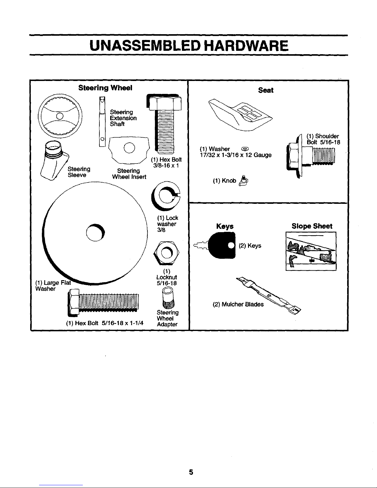
UNASSEMBLED HARDWARE
Steering Wheel
/_Steedng vV_tee_l_nnsgert -
Sleeve
(1) Lock
washer
3/8
(1)Large
Washer
(1) Hex Bolt 5/16-18 x 1ol/4
(1)
Locknut
5/16-18
Steering
Wheel
Adapter
Seat
(1) Washer
17/32 x 1-3/16 x 12 Gauge
(1) Shoulder
Bolt 5/16-18
(1) Knob
Keys
(2) Keys
Slope Sheet
(2) Mulch_
5
ASSEMBLY
Your new tractor has been assembled at thefactory with exception ofthose partsleft unassembled for shippingpurposes. To
ensure safe and proper operation of yourtractor all parts and hardware you assemble must be tightened securely. Use the
correct tools as necessary to insure proper tightness.
TOOLS REQUIRED FOR ASSEMBLY
A socket wrench set will make assembly easier. Standard
wrench sizes are listed,
(2) 1/2" wrenches Utility knife
(1) 9/16" wrench Tire pressuregauge
Pliers
When rightorleft hand is mentionedinthis manual, itmeans
when you are in the operating position (seated behind the
steering wheel).
TO REMOVE TRACTOR FROM CARTON
UNPACK CARTON
• Remove all accessible loose parts and parts cartons
from carton.
• Cut, from top to bottom, along lines on all four corners
of carton, and lay panels fiat.
• Check for any additional loose parts or cartons and
remove.
BEFORE REMOVING TRACTOR FROM
SKID
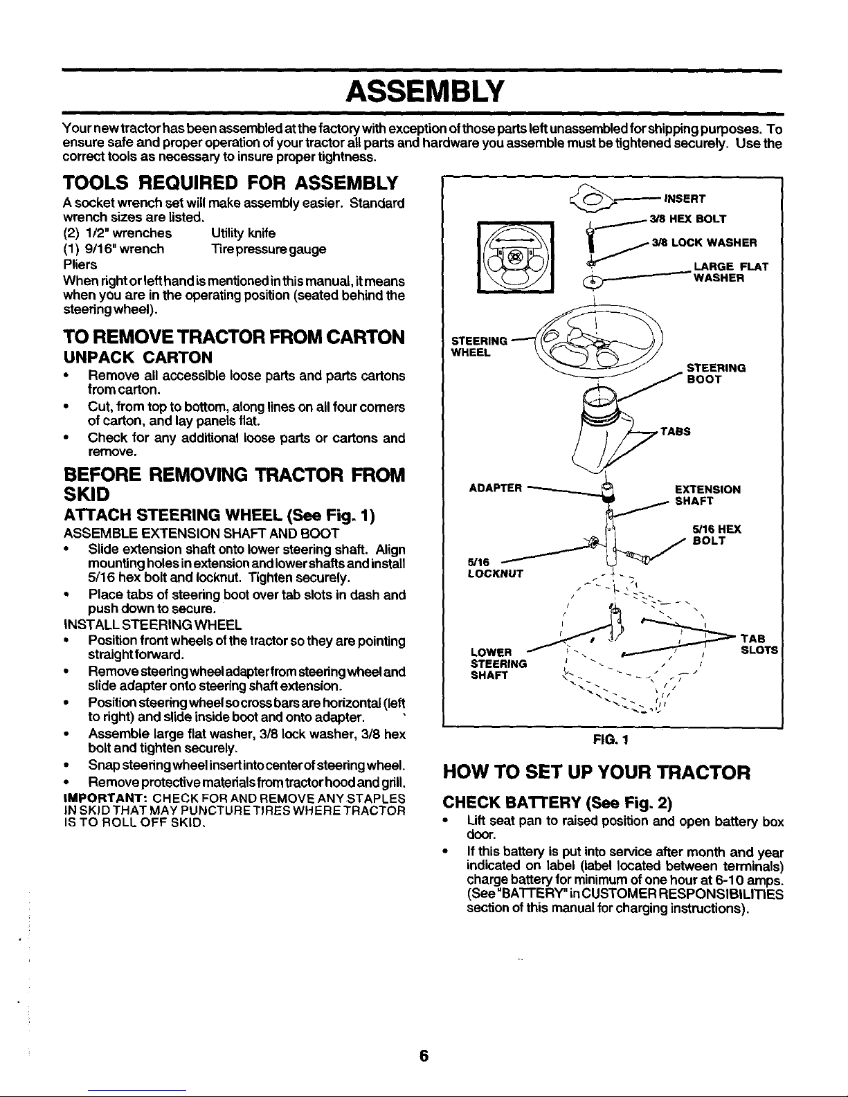
ATTACH STEERING WHEEL (See Fig. 1)
ASSEMBLE EXTENSION SHAFT AND BOOT
• Slide extension shaft onto lower steering shaft. Align
mounting holes inextensionand lowershafts and install
5/16 hex bolt and Iocknut. Tighten securely.
• Place tabs of steering boot over tab slots in dash and
push down to secure.
INSTALL STEERING WHEEL
• Position front wheels of the tractorso they are pointing
straightforward.
• Remove steering wheeladapter fromsteeringwheel and
slide adapter onto steering shaft extension.
• Position steering wheel socrossbars are horizontal (left
to right) and slide inside bootand onto adapter.
• Assemble large flat washer, 3/8 lock washer, 3/8 hex
bolt and tighten securely.
• Snap steering wheel insertintocenterof steering wheel.
• Remove pretective materialsfremtractorhood and grill.
IMPORTANT: CHECK FOR AND REMOVE ANY STAPLES
IN SKID THAT MAY PUNCTURE TIRES WHERE TRACTOR
IS TO ROLL OFF SKID,
;r--_ INSERT
-. 3/8 HEX BOLT
3/8 LOCK WASHER
, LARGE FLAT
(_/WASHER
STEERINI
WHEEL
ABAPTER
LOCKNUT
s
EXTENSION
_16 HEX
BOLT
FIG. 1
HOW TO SET UP YOUR TRACTOR
CHECK BA'I-I'ERY (See Fig. 2)
• Lift seat pan to raised position and open battery box
door.
• If this battery is put into service after month and year
indicated on label (label located between terminals)
charge battery for minimum of one hour at 6-10 amps.
(See "BATTERY" inCUSTOMER RESPONSIBILITIES
section of this manual for charging instructions).
6

i i
ASSEMBLY
i
BOX
LABEL
FIG. 2
INSTALL SEAT (See Fig. 3)
Adjust seat before tightening adjustment knob.
• Remove adjustment knobandflatwasher securingseat
tocardboard packing and setaside for assemblyofseat
to tractor.
• Pivot seat upward and remove from the cardboard
packing. Remove the carboard packing and discard.
• Place seat on seat pan and assemble shoulder bolt.
Tighten shoulder bolt securely.
• Assembleadjustmentknobandflatwasherloosely. Do
not tighten.
• Lower seat into operating positionand sit on seat.
• Slide seat untila comfortable positionisreached which
allows youto press clutch/brake pedal alltheway down,
• Get off seat without moving itsadjusted position.
• Raise seat and tighten adjustment knob securely.
SEAT
SEAT PAN
ADJUSTMENT
KNOB WASHER
TO ROLL TRACTOR OFF SKID (See Opera-
tion section, page 10, for location and
function of controls)
• Press lift lever plunger and raise attachment liftlever to
its highest position.
• Release parkingbrekebydepressingclutch/brakepedal.
• Place gearshift leverin neutral (N) position.
• Rolltractor forward off skid.
• Remove banding holding discharge guard up against
tractor.
TO DRIVE TRACTOR OFF SKID (See Opera-
tion section, page 10, for location and func-
tion of controls)
& WARNING: Before starting, read,understand and follow
all instructions in the Operation section of this manual. Be
sure tractor is in a well-ventilated area. Be sure the area in
front of tractor is clear ofother people and objects.
• Be sure all the above assembly steps have been
completed.
• Check engine oil level and fill fuel tank with gasoline.
• Sit on seat inoperating position,depress clutch/brake
pedal and set the parking brake.
• Place gear shiftlever in neutral (N) position.
• Press liftlever plunger and raiseattachment liftlever to
its highest position.
• Startthe engine. Afterengine hasstarted, move throttle
control to idleposition.
• Depress clutch/brake pedal intofull "BRAKE" position
and hold. Move gearshift lever to 1st gear.
• Slowly release clutch/brake pedal and slowly drive
tractor off skid.
• Apply brake tostop tractor,set parking brake and place
gearshift lever in neutral position.
, Turn ignition key to"OFF" position.
Continue with the instructionsthatfollow.
FIG. 3
NOTE: You may now rollor drive your tractor offthe skid.
Follow the appropriate instruction below to remove the
tractor from the skid.
7
ASSEMBLY
CHECK TIRE PRESSURE
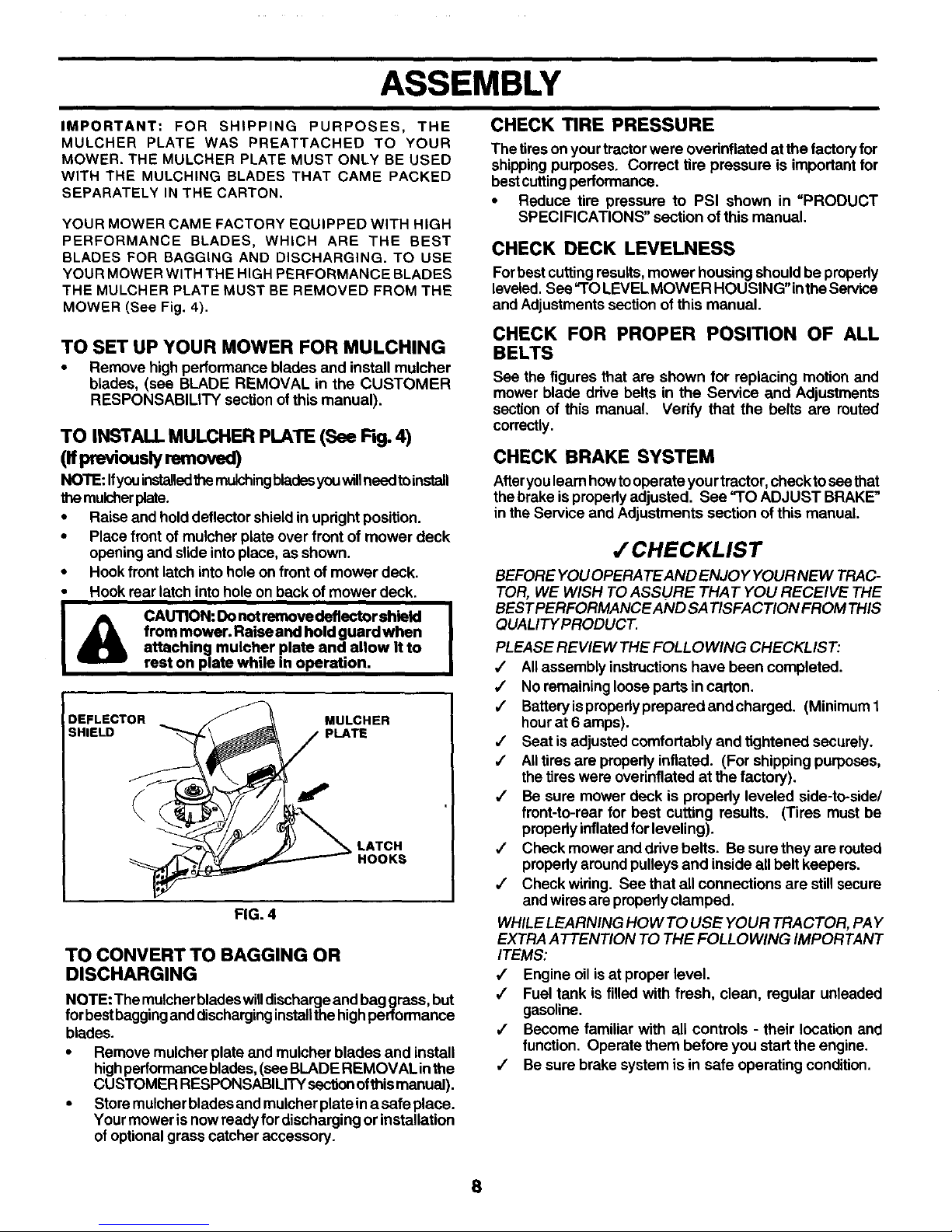
IMPORTANT: FOR SHIPPING PURPOSES, THE
MULCHER PLATE WAS PREATTACHED TO YOUR
MOWER. THE MULCHER PLATE MUST ONLY BE USED
WITH THE MULCHING BLADES THAT CAME PACKED
SEPARATELY IN THE CARTON.
YOUR MOWER CAME FACTORY EQUIPPED WITH HIGH
PERFORMANCE BLADES, WHICH ARE THE BEST
BLADES FOR BAGGING AND DISCHARGING. TO USE
YOUR MOWER WITH THE HIGH PERFORMANCE BLADES
THE MULCHER PLATE MUST BE REMOVED FROM THE
MOWER (See Fig. 4).
TO SET UP YOUR MOWER FOR MULCHING
• Remove high performance blades and install mulcher
blades, (see BLADE REMOVAL in the CUSTOMER
RESPONSABILITY section of this manual).
TO INSTALL MULCHER PLATE (See Fig. 4)
(nFeviouslyremoved)
NOTE: Ifyouinstalledfile rnulchingbladesyouwillneedtoinstall
the mulcher plate.
• Raise and hold deflector shield in updght position.
• Place front of mulcher plate over front of mower deck
opening and slide into place, as shown.
• Hook front latch into hole on front of mower deck.
• Hook rear latch into hole on back of mower deck.
from mower. Raise and hold guard when
attaching mulcher plate and allow it to
rest on plate while in operation.
DEFLECTOR MULCHER
SHIELD
LATCH
HOOKS
FIG. 4
TO CONVERT TO BAGGING OR
DISCHARGING
NOTE: Themulcherblades willdischargeand bag grass, but
forbestbaggingand discharging installthe highperformance
blades.
• Remove mulcher plate and muicher blades and install
highperformanceblades, (see BLADE REMOVAL inthe
CUSTOMER RESPONSABILITY section ofthis manual).
• St°re mulcher blades and muicherplata ina safe place"
Yourmower isnow ready fordischarging or installation
of optional grass catcher accessory.
The tireson yourtractor were ovednflated at the factoryfor
shippingpurposes. Correct tire pressure is important for
bestcuffingperformance.
• Reduce tire pressure to PSI shown in "PRODUCT
SPECIFICATIONS" section of this manual.
CHECK DECK LEVELNESS
Forbest cuffing results, mower housing should be properly
leveled, See =TOLEVELMOWER HOUSING" inthe Service
and Adjustments section of this manual.
CHECK FOR PROPER POSITION OF ALL
BELTS
See the figures that are shown for replacing motion and
mower blade drive belts in the Service and Adjustments
section of this manual, Verify that the belts are routed
correctly.
CHECK BRAKE SYSTEM
After you learn howtooperate your tractor,check to see that
thebrake isproperly adjusted. See "TO ADJUST BRAKE"
in the Service and Adjustments section of this manual.
,/'CHECKLIST
BEFORE YOUOPERA TEAND ENJOY YOUR NEW TRAC-
TOR, WE WISH TO ASSURE THAT YOU RECEIVE THE
BEST PERFORMANCE AND SATISFACTION FROM THIS
QUALITY PRODUCT.
PLEASE REVIEW THE FOLLOWING CHECKLIST:
•/ All assembly instructions have been completed.
,/ No remaining loose parts in carton.
,,/ Battery isproperly prepared and charged. (Minimum 1
hour at6 amps).
,/ Seat is adjusted comfortably and tightened securely.
/ All tires are properly inflated. (For shipping purposes,
the tires were overinflated at the factory).
•/ Be sure mower deck is properly leveled side-to-side/
front-to-rear for best cutting results. (Tires must be
propedy inflated for leveling).
4' Check mower and drive belts. Be sure they are routed
propedy around pulleys and inside all belt keepers.
,/ Check wiring. See that allconnections are still secure
and wires are properly clamped.
WHILE LEARNING HOW TO USE YOUR TRACTOR, PAY
EXTRA ATTENTION TO THE FOLLOWING IMPORTANT
ITEMS:
,/ Engine oil is at proper level.
,/ Fuel tank is filled with fresh, clean, regular unleaded
gasoline.
/ Become familiar with all controls - their location and
function. Operate them before you start the engine.
•/ Be sure brake system is in safe operating condition.
8
OPERATION
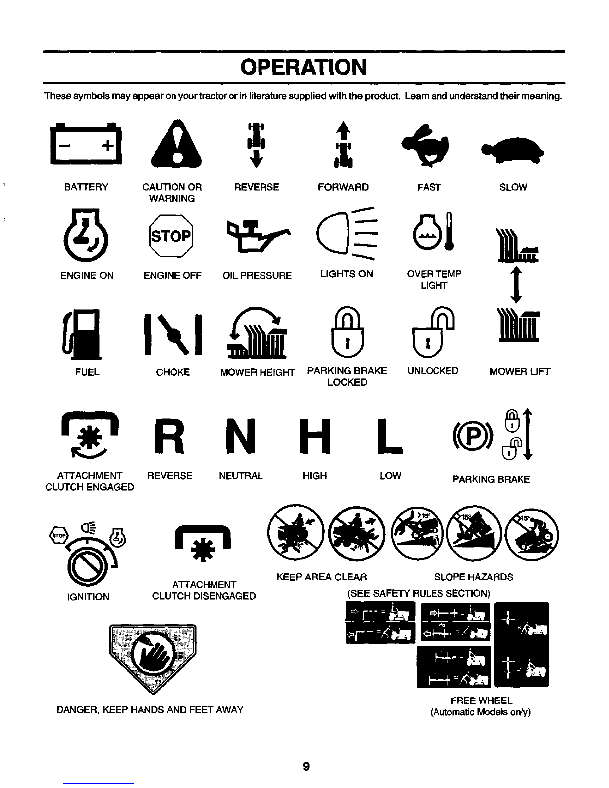
These symbols may appear on your tractoror in literaturesupplied with the product. Learnand understand their meaning.
BAI-rERY CAUTION OR REVERSE FORWARD FAST SLOW
WARNING
ENG,NEOHENG,NEOFFO,'PRESSORE',GHTSONOV_._T_.PI
FUEL CHOKE MOWER HEIGHT PARKING BRAKE UNLOCKED MOWER LIFT
LOCKED
N H
AI-rACHMENT REVERSE
CLUTCH ENGAGED
IGNITION
A'I-I'ACHMENT
CLUTCH DISENGAGED
NEUTRAL HIGH LOW
PARKING BRAKE
KEEP AREA CLEAR SLOPE HAZARDS
(SEE SAFETY RULES SECTION)
DANGER, KEEP HANDS AND FEET AWAY
FREE WHEEL
(AutomaticModelsonly)
9
i
OPERATION
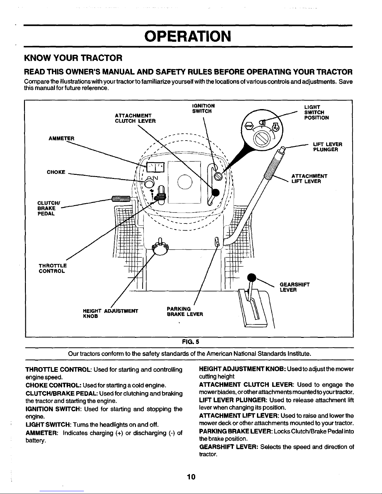
KNOW YOUR TRACTOR
READ THIS OWNER'S MANUAL AND SAFETY RULES BEFORE OPERATING YOUR TRACTOR
Compare the illustrationswith your tractorto familiarize yourself withthe locations ofvarious controls and adjustments. Save
this manual for future reference.
ATTACHMENT
CLUTCH LEVER
IGNITION LIGHT
SWITCH SWITCH
POSITION
AMMETER
'_ UFTLEVER
PLUNGER
CHOKE
ATTACHMENT
LIFT LEVER
CLUTCH/
BRAKE
PEDAL
THROTTLE
CONTROL
GEARSHIFT
LEVER
HEIGHT ADJUSTMENT
KNOB
BRAKE LEVER
FIG. 5
Our tractors conform to the safety standards of theAmerican National Standards Institute.
THROTrLE CONTROL: Used for starting and controlling
engine speed.
CHOKE CONTROL: Used for starting a cold engine.
CLUTCH/BRAKE PEDAL: Used for clutching and braking
the tractor and starting the engine.
IGNITION SWITCH: Used for starting and stopping the
engine.
UGHT SWITCH: Turns the headlights on and off.
AMMETER: Indicates charging (+) or discharging (-) of
battery.
HEIGHT ADJUSTMENT KNOB: Used toadjustthe mower
cuffingheight
A'rrACHMENT CLUTCH LEVER: Used to engage the
mowerblades, orotherattachments mounted toyourtractor.
LIFT LEVER PLUNGER: Used to release attachment lift
leverwhen changing its position.
AI"rACHMENT LIFT LEVER: Used to raise and lower the
mowerdeck orother attachments mounted to your tractor.
PARKING BRAKE LEVER: Locks Clutch/Brake Pedal into
the brake position.
GEARSHIFT LEVER: Selects the speed and direction of
tractor.
10
OPERATION
The operation of any tractor can result inforeign objects thrown into the eyes, which can
result in severe eye damage. Always wear safety glasses or eye shields while operating
your tractor or performing any adjustments or repairs. We recommend a wide vision
safety mask over spectacles or standard safety glasses.
i
HOW TO USE YOUR TRACTOR I & CAUTION: Always atop tra_-_or _om-
pletely, as described above, before leav-
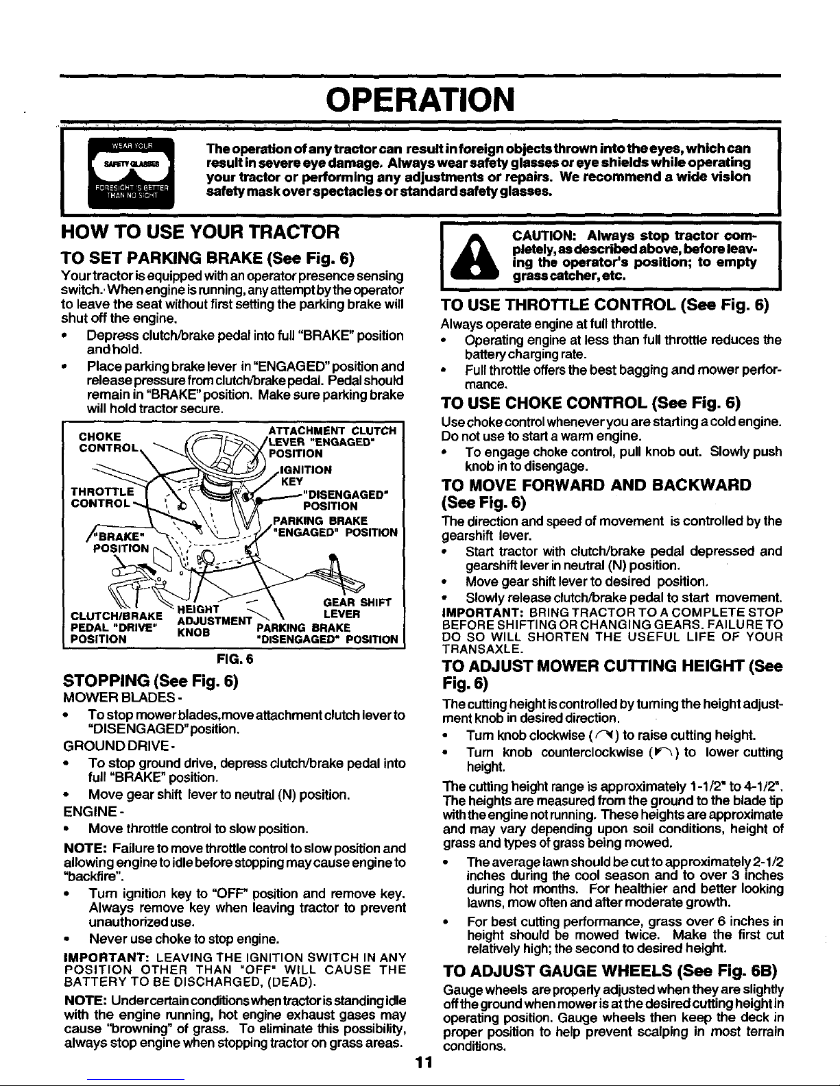
TO SET PARKING BRAKE (See Fig. 6)
Your tractor isequipped with anoperator presence sensing
switch.=When engineisrunning,anyattempt by theoperator
to leave the seat without first settingthe parking brake will
shut off the engine.
• Depress clutch/brake pedal intofull "BRAKE" position
and hotd.
• Place parking brake lever in"ENGAGED" position and
release pressurefrom clutch/brakepedal. Pedal should
remain in "BRAKE"position. Make sure parking brake
will hold tractor secure.
ing the operator's position; to empty
grass catcher, etc.
TO USE THROTI'LE CONTROL (See Fig. 6)
Always operate engine at fullthrottle.
• Operating engine at less than full throttle reduces the
battery charging rate.
• Full throttle offersthe best bagging and mower perfor-
mance.
C"oO oL
c
POSITION
CLUTCH/BRAKE
PEDAL "DRIVE"
POSITION
ATTACHMENT CLUTCH
fLEVER "ENGAGED"
,,-, POSITION
gTiON
-----'POBIT,oHO'SEHGAGED"
PARKING BRAKE
""ENGAGED" POSITION
GEAR SHIFT
HEIGHT _ LEVER
ADJUSTMENT "_
KNOB PARKING BRAKE
"DISENGAGED" POSITION
FIG. 6
STOPPING (See Fig. 6)
MOWER BLADES -
• To stop mower blades,move attachment clutchlever to
"DISENGAGED"position.
GROUND DRIVE-
• To stop ground ddve, depress clutch/brake pedal into
full "BRAKE" position.
• Move gear shift lever to neutral (N) position.
ENGINE -
• Move throttle control to slow position.
NOTE: Failure to move throttle controlto slow positionand
allowing engine toidle beforestoppingmay cause engine to
=backfire".
• Turn ignition key to "OFF* position and remove key.
Always remove key when leaving tractor to prevent
unauthorized use.
• Never use choke tostop engine,
IMPORTANT: LEAVING THE IGNITION SWITCH IN ANY
POSITION OTHER THAN "OFF" WILL CAUSE THE
BATTERY TO BE DISCHARGED, (DEAD).
NOTE: Under certainconditionswhentractor isstandingidle
with the engine running, hot engine exhaust gases may
cause "browning" of grass. To eliminate this possibility,
always stop engine when stoppingtractor on grass areas.
11
TO USE CHOKE CONTROL (See Fig. 6)
Use choke controlwhenever you are startinga cold engine.
Do not use to start a warm engine.
• To engage chokecontrol, pull knob out. Slowly push
knob in todisengage.
TO MOVE FORWARD AND BACKWARD
(See Fig. 6)
The directionand speed of movement is controlled by the
gearshift lever.
• Start tractor with clutch/brake pedal depressed and
gearshift lever inneutral (N) position.
• Move gear shiftleverto desired position,
• Slowly release clutch/brake pedal to start movement.
IMPORTANT: BRING TRACTOR TO A COMPLETE STOP
BEFORE SHIFTING OR CHANGING GEARS. FAILURE TO
DO SO WILL SHORTEN THE USEFUL LIFE OF YOUR
TRANSAXLE.
TO ADJUST MOWER CUTTING HEIGHT (See
Fig. 6)
The cuttingheight iscontrolledby turning the height adjust-
ment knob in desired direction.
• Tum knob clockwise(/_l) to raise cutting height.
• Tum knob counterclockwise (1,_) to lower cutting
height.
The cuttingheight range is approximately 1-1/2" to4-1/2".
The heights are measured from the ground to the blade tip
withtheengine notrunning. These heights are approximate
and may vary depending upon soil conditions, height of
grass and types of grassbeing mowed.
• Theaveragelawnshouldbecuttoapproximately2-t/2
inches during the cool season and to over 3 inches
during hot months. For healthier and better looking
lawns, mow oftenand after moderate growth.
• For best cutting performance, grass over 6 inches in
height should be mowed twice. Make the first cut
relatively high;thesecond to desired height.
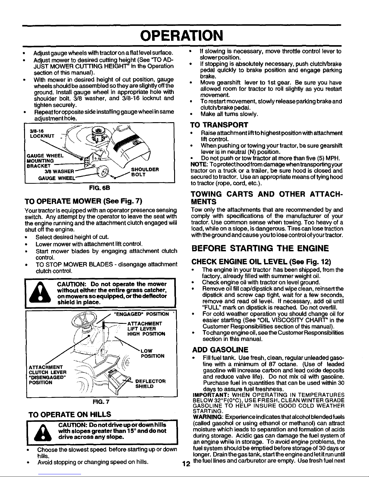
TO ADJUST GAUGE WHEELS (See Fig. 6B)
Gauge wheels areproperly adjusted when they are slightly
offthe groundwhen mower isatthe dasired cutting height in
operating position. Gauge wheels then keep the deck in
proper position to help prevent scalping in most terrain
conditions,
OPERATION
• Adjustgauge wheels withtractor on a flat level surface. •
• Adjust mower to desired cutting height (See =TO AD-
JUST MOWER CU'I-I'ING HEIGHT" in the Operation °
section of this manual).
With mower in desired height of cut position, gauge •
wheels shouldbe assembled so they are slightlyoffthe
ground. Install gauge wheel in appropriate hole with
shoulder bolt, 3/8 washer, and 3/8-16 Iocknut and
tighten securely.
Repeat foropposite side installinggauge wheel insame
adjustment hole.
3/8-16
LOCKNUT
P-AUGE WHEEL
MOUNTING
BRACKET
3/8V
SHOULDER
FIG. 6B
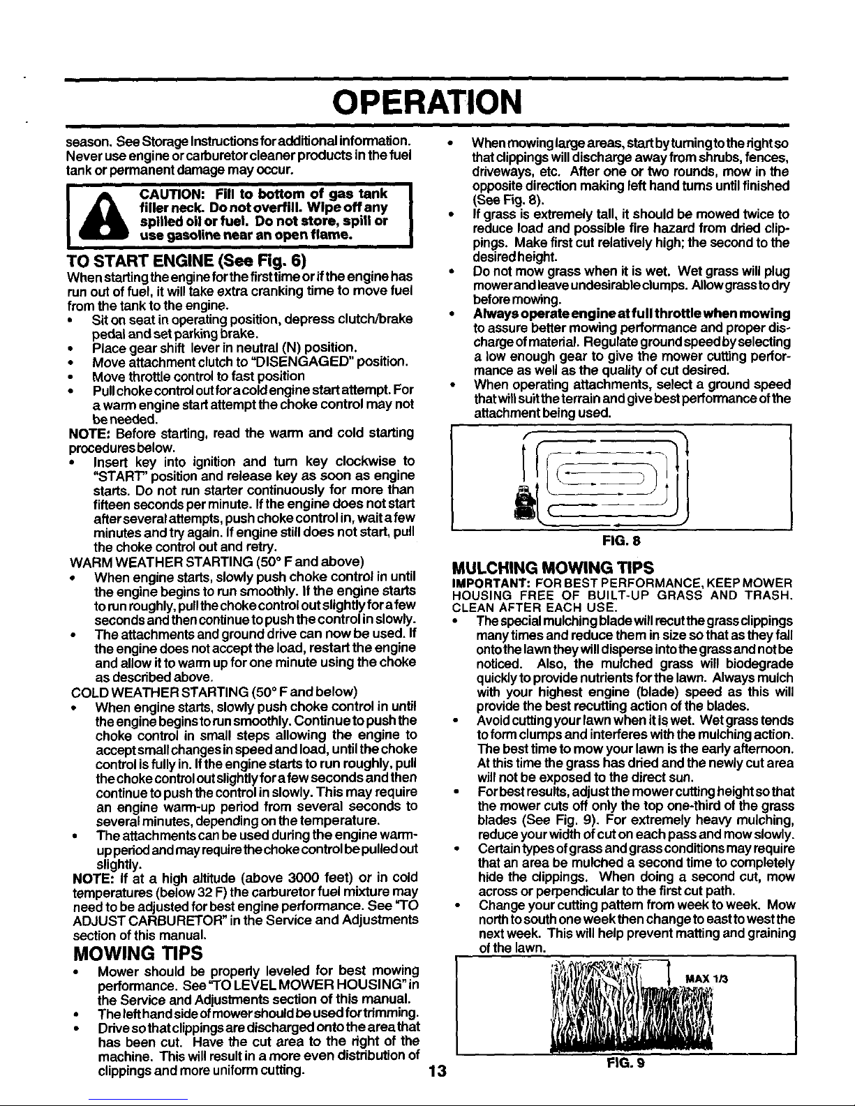
TO OPERATE MOWER (See Fig. 7)
Your tractor is equipped with an operator presence sensing
switch. Any attempt by the operator to leave the seatwith
the engine running and the attachment clutch engaged will
shut offthe engine.
• Select desired height ofcut.
• Lowermower with attachment liftcontrol.
• Start mower blades by engaging attachment clutch
control.
• TO STOP MOWER BLADES - disengage attachment
clutchcontrol.
&
CAUTION: Do not operate the mower
without either the entire grass catcher,
on mowers so equipped, or the deflector
shield in place.
"ENGAGED" POSITION
LIFT LEVER
HIGH POSITION
ATTACHMENT
CLUTCH LEVER
"DISENGAGED"
POSITION
LOW
POSITION
SHIELD
FIG. 7
TO OPERATE ON HILLS
I & CAUTION: Donotdriveupordownhills I
with slopes greater than 15° and do not
drive across any slope.
• Choose the slowest speed before starting upor down
hills.
• Avoid stoppingor changing speed on hills.
If slowing is necessary, move throttle control lever to
slower position.
If stopping is absolutely necessary, pushclutch/brake
pedal quickly to brake position and engage parking
brake.
Move gearshift lever to 1st gear. Be sure you have
allowed room for tractor to roll slightly as you restart
movement.
To restart movement, slowly release parkingbrake and
clutch/brake pedal.
Make all tums slowly.
TO TRANSPORT
• Raise attachment lifttohighest positionwith attachment
lift control.
• When pushing or towing your tractor, be sure gearshift
lever is in neutral (N) position.
• Do notpush ortow tractor at more than five (5) MPH.
NOTE: To protect hoodfrom damage when transportingyour
tractor on a truck or a trailer, be sure hood is closed and
secured to tractor. Use an appropriate means oftyinghood
to tractor (rope, cord, etc.).
TOWING CARTS AND OTHER ATTACH-
MENTS
Tow only the attachments that are recommended by and
comply with specifications of the manufacturer of your
tractor. Use common sense when towing. Too heavy of a
load, while on a slope, is dangerous. Tires can lose traction
withtheground and cause you to lose controlof yourtractor.
BEFORE STARTING THE ENGINE
12
CHECK ENGINE OIL LEVEL (See Fig. 12)
• The engine in your tractor has been shipped, fromthe
factory, already filled with summer weightoil.
• Check engine oil with tractor on level ground.
• Remove oilfillcap/dipstick and wipeclean, reinsertthe
dipstick and screw cap tight, wait for a few seconds,
remove and read oil level. If necessary, add oil until
"FULL" mark on dipstick is reached. Do not overfill.
• For cold weather operation you should change oil for
easier starting (See "OIL VISCOSITY CHART" in the
Customer Responsibilities section of this manual).
• Tochange engine oil, see the Customer Responsibilities
section in this manual
ADD GASOLINE
• Fillfueltank. Use fresh, clean, regularunleadedgaso-
line with a minimum of 87 octane. (Use of leaded
gasoline will increase carbon and lead oxide deposits
and reduce valve life). Do not mix oil with gasoline.
Purchase fuel inquantities that can be used within30
days to assure fuel freshness.
IMPORTANT: WHEN OPERATING IN TEMPERATURES
BELOW 32°F(0°C), USE FRESH, CLEAN WINTER GRADE
GASOLINE TO HELP INSURE GOOD COLD WEATHER
STARTING.
WARNING: Experience indicates that alcoholblendedfuels
(called gasohol or using ethanol or methanol) can attract
moisture which leads to separation and formation of acids
during storage. Acidic gas can damage the fuel system of
an engine while in storage. To avoid engine problems, the
fuel system should be emptied before storage of30 daysor
longer. Drain the gas tank, start the engineand let itrununtil
thefuel linesand carburetor are empty. Use fresh fuel next
OPERATION
season. SeeStorage Instructionsforadditional information.
Never use engine orcarburetor cleaner products in the fuel
tank or permanent damage may occur.
I&C O o.,o_°o.i
filler neck. Donot overfill. Wlpeoffany
spilled oil or fuel. Do not store, spill or
use gasoline near an open flame.
TO START ENGINE (See Fig. 6)
When startingthe enginefor the first time or if theengine has
runout offuel, it will take extra cranking time to move fuel
from the tank to the engine.
• Sit on seat in operating position, depress clutch/brake
pedal and set parking brake.
• Place gear shift lever in neutral (N) position.
• Move attachment clutch to =DISENGAGED" position.
• Move throttle controlto fast position
• Pullchokecontroloutfor a cold engine start attempt. For
a warm engine start attempt the choke control may not
be needed.
NOTE: Before starting, read the warm and cold starting
proceduresbelow.
• Insert key into ignition and turn key clockwise to
"START" position and release key as soon as engine
starts. Do not run starter continuously for more than
fifteen seconds per minute. Ifthe engine does not start
afterseveral attempts, pushchoke control in, wait a few
minutes and try again. Ifengine stilldoes notstart, pull
the choke controlout and retry.
WARM WEATHER STARTING (50° F and above)
• When engine starts, slowly push choke control in until
the engine begins to run smoothly. It the engine starts
torun roughly,pullthechoke controloutslightly for afew
seconds and thencontinue topush the control inslowly.
• The attachments and ground drive can now be used. If
the engine does not accept the load, restart the engine
and allow itto warm upfor one minute using the choke
as described above,
COLD WEATHER STARTING (50 ° Fand below)
• When engine starts, slowly push choke control in until
theengine beginstorunsmoothly. Continue to pushthe
choke control in small steps allowing the engine to
accept small changes inspeed and load, untilthe choke
controlisfully in. Ifthe engine starts to run roughly, pull
the choke controloutslightlyfora few seconds and then
continue to pushthe control in slowly. This may require
an engine warm-up period from several seconds to
several minutes, depending on the temperature.
• The attachments canbe used during the engine warm-
upperied and may requirethe choke controlbe pulled out
slightly.
NOTE: If at a high altitude (above 3000 feet) or in cold
temperatures (below 32 F)the carburetor fuel mixture may
need to be adjusted forbest engine performance. See _1"O
ADJUST CARBURETOR" inthe Service and Adjustments
section of this manual.
MOWING TIPS
• Mower should be properly leveled for best mowing
performance. See "TO LEVEL MOWER HOUSING" in
the Service and Adjustments section of this manual.
• The left hand sideofmower should be used fortrimming.
• Ddvesothatclippingsaradischargedontotheareathat
has been cut. Have the cut area to the dght of the
machine. This willresult in a more even distribution of
clippingsand more uniform cuffing. 13
When mowinglarge areas, sta/t by turningtotherightso
thatclippingswilldischarge away from shrubs,fences,
driveways, etc. After one or two rounds, mow in the
oppositedirection making left hand tums untilfinished
(See Fig. 8).
• If grass is extremely tall, it should be mowed twice to
reduce load and possible fire hazard from dried clip-
pings. Make first cut relatively high; the second to the
desiredheight.
• Do not mow grass when it is wet. Wet grass will plug
mowerandleave undesirableclumps. Allowgrass to dry
beforemowing.
• Always operste engine st full throttle when mowing
to assure better mowing performance and proper dis-
chargeofmaterial. Regulate groundspeed by selecting
a low enough gear to give the mower cutting perfor-
mance as well as the quality of cut desired.
• When operating attachments, select a ground speed
thatwillsuitthe terrain and give best performance ofthe
attachment being used.
FIG. 8
MULCHING MOWING TIPS
IMPORTANT: FOR BEST PERFORMANCE, KEEPMOWER
HOUSING FREE OF BUILT-UP GRASS AND TRASH.
CLEAN AFTER EACH USE.
• The specialmulchingbladewill recutthe grassclippings
manytimes and reduce them insize so that as they fall
ontothe lawnthey willdisperse intothe grass and notbe
noticed. Also, the mulched grass will biodegrade
quicklytoprovide nutrients for the lawn. Always mulch
with your highest engine (blade) speed as this will
providethe best recutting action of the blades.
• Avoidcuffingyour lawn when itis wet. Wet grass tends
toform clumpsand interferes with the mulchingaction.
The best time to mow your lawn isthe early afternoon.
Atthistime the grass has dried and the newly cutarea
willnot be exposed to the direct sun.
• Forbest results,adjust the mower cuttingheightsothat
the mower cuts off only the top one-third of the grass
blades (See Fig. 9). For extremely heavy mulching,
reduceyourwidth ofcut on each pass and mow slowly.
• Certaintypes ofgrass and grassconditionsmay require
that an area be mulched a second time to completely
hide the clippings. When doing a second cut, mow
across or perpendicular to the firstcut path.
• Change your cutting pattern from week to week. Mow
northtosouth one week then change to east towestthe
nextweek. This will help prevent matting and graining
ofthe lawn.
FIG. 9
MAX 1/3
i ii
CUSTOMER RESPONSIBILITIES
FILL IN DATES
ASYOOCOMP, E
Check Brake Operation _
Check Tire Pressure
Check Operator Presence and
T Irdedock Systems
B Check for Loose Fasteners I_ 1_'7
A Sharpen/Replace Mower Blades _4
T Lubdcation Chart ,
0 Check Battery Level
R Clean Battery and Terminals I_
Check Trenssxle Cooling
Adjust Blade Belt(s) Tension II_s
Adjust Motion Drive Belt(s) Tension _s
Check Engine Oil Level _ ll_
Change Engine Oil I_t2,_ I_
E Clean Air Filter _
i N Clean Air Screen
i (_ Inspect Muffler/Spark Arrester
/ Replace Oil Filter (If equipped) 11_1,2
I E I Clean Engine Cooling Fins 11_2
Replace Spark Plug I_ ll_
Replace Air Filter Paper Cartridge
Replace Fuel Filter I_'
1 .Cbangemomoftenwhenoperatingunderapeavylondoriohighambientternperotures. 5-ffeqaipeedwithadjuotablesystem.
2 - Service more often whe_ operating in dirty or dustyconditions, 6 - Not requiredff equippedwith maintenance-fleebattery.
3 - If equipped with oil filter, change oil every 50 hours. 7 - Tightenfront axle pivot bait to 35 It._bs. maximum,
4 - Replace blades more (}hen when mowingio sandysail I3o not overitghten.
GENERAL RECOMMENDATIONS
The warranty on this tractor does not cover itemsthat have
been subjected tooperator abuse ornegligence. To receive
full value from the warranty, operator must maintaintractor
as instructed in this manual.
Some adjustments will need to be made periodically to
properlymaintain your tractor.
Alladjustments inthe Service and Adjustments section of
this manual should be checked at least once each season.
• Once s yearyou shouldreplace the spark plug,clean or
replace airfilter, and check blades and beltsforwear. A
new spark plug and clean air filterassu reproperair-fuel
mJxtureand help your engine runbetter andlastlonger.
BEFORE EACH USE
• Check engine oil level.
• Checkbrake operation.
• Check tire pressure.
• Check operator presence and
interlocksystems for proper operation,
• Check for loose fasteners.
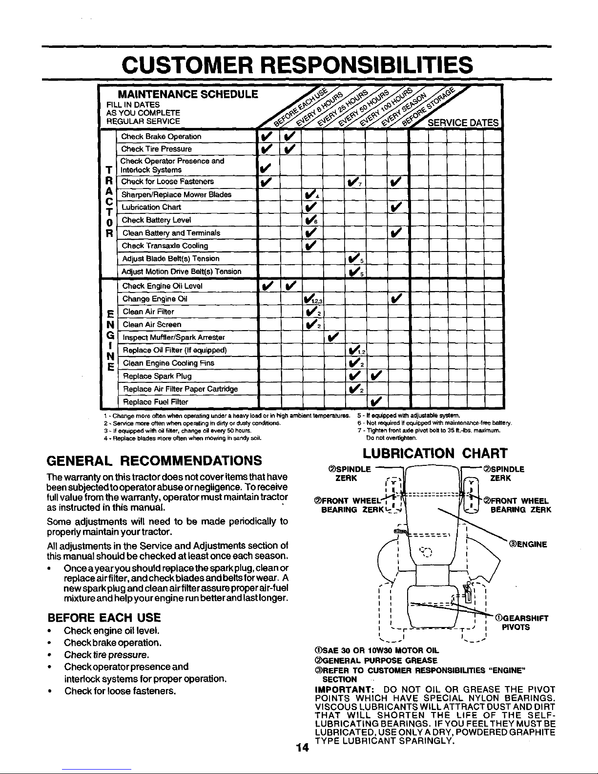
LUBRICATION CHART
(_SPINDLE
ZERK ZERK
(_FRONT '_)FRONT WHEEL
BEARING ZERK SEARING ZERK
14
I
I
t T - _ PIVOTS
(_)SAE 30 OR 10W30 MOTOR OIL
_GENERAL PURPOSE GREASE
_)REFER TO CUSTOMER RESPONSIBILITIES "ENGINE"
SECTION
IMPORTANT: DO NOT OiL OR GREASE THE PIVOT
POINTS WHICH HAVE SPECIAL NYLON BEARINGS.
VISCOUS LUBRICANTS WILL ATTRACT DUST AND DIRT
THAT WILL SHORTEN THE LIFE OF THE SELF-
LUBRICATING BEARINGS. IF YOU FEEL THEY MUST BE
LUBRICATED, USE ONLY A DRY, POWDERED GRAPHITE
TYPE LUBRICANT SPARINGLY.
CUSTOMER RESPONSIBILITIES
MANDREL
ASSEMBLY
TRACTOR
Always observe safety rules when performing any mainte-
nance.
BRAKE OPERATION
Iftractorrequiresmore than six (6) feet stopping distance at
high speed inhighest gear, then brake must be adjusted.
(See "TOADJUST BRAKE" inthe Service and Adjustments
section of this manual).
TIRES
• Maintain properair pressure inalltires (See"PRODUCT
SPECIFICATIONS" section ofthis manual).
• Keep tiresfree ofgasoline, oil, or insect control chemi-
calswhich can harm rubber.
• Avoid stumps, stones, deep ruts, sharp objects and
other hazards that may cause tire damage.
NOTE: To seal tire punctures and prevent flat tires due to
slow leaks, tire sealant may be purchased from your local
parts dealer. Tire sealant also prevents tire dry rot and
corrosion.
OPERATOR PRESENCE SYSTEM
Besure operator presence and intedock systems are work-
ingproperly. Ifyour tractor does not function as described,
repairthe problem immediately.
• The engine should not start unless the clutch/brake
pedal isfully depressed and attachement clutchcontrol
is inthe disengaged position.
• When the engine isrunning, any attempt bytheoperator
to leave the seat without first setting the parking brake
should shut offthe engine.
• When the engine isrunning and the attachment clutchis
engaged, any attempt by the operator to leave the seat
should shut offthe engine.
• The attachment clutch should never operate unless the
operator isin the seat.
BLADE CARE
Forbest resultsmower blades mustbe kept sharp. Replace
bentor damaged blades.
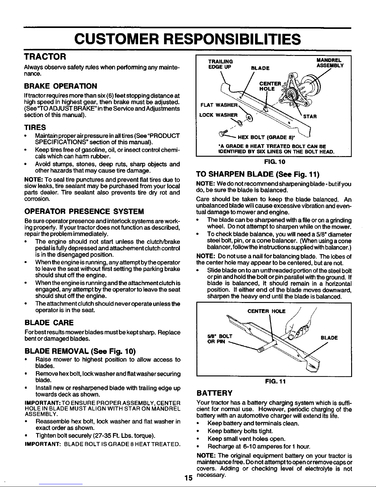
BLADE REMOVAL (See Fig. 10)
• Raise mower to highest position to allow access to
blades.
• Remove hexbolt, lockwasher and flat washer securing
blade.
• Install new or resharpened blade with trailingedge up
towards deck asshown.
IMPORTANT: TO ENSURE PROPER ASSEMBLY, CENTER
HOLE IN BLADE MUST ALIGN WITH STAR ON MANDREL
ASSEMBLY.
• Reassemble hex bolt, lock washer and flat washer in
exact order as shown.
• Tighten bolt securely (27-35 Ft. Lbs. torque).
IMPORTANT: BLADE BOLT IS GRADE 8 HEAT TREATED.
TRAILING
EDGE UP BLADE
CENTER
HOLE
FLAT WASHER _,
LOCK WASHER
_"- HEX BOLT (GRADE 8)*
*A GRADE 8 HEAT TREATED BOLT CAN BE
IDENTIRED BY SiX LINES ON THE BOLT HEAD.
FIG. 10
TO SHARPEN BLADE (See Fig. 11)
NOTE: We do not recommend shaq0eningblade- butifyou
do, be surethe blade is balanced.
Care should be taken to keep the blade balanced. An
unbalanced blade willcause excessive vibrationandeven-
tual damage tomower and engine.
• The bladecan be sharpened withafile oron a gdnding
wheel. Do not attempt to sharpen while onthe mower.
• To check blade balance, you will need a 5/8" diameter
steel bolt, pin, or a cone balancer. (When usingacone
balancer, follow the instructions suppliedwithbalancer.)
NOTE: Do notuse a nail for balancing blade. The lobesof
the center holemay appear to be centered, but are not.
• Slide blade on to an unthreaded portionofthesteel bolt
or pin and hold the bolt or pin parallel withthe ground. If
blade is balanced, it should remain in a horizontal
position. If either end of the blade moves downward,
sharpen the heavy end until the blade isbalanced.
CENTER HOLE
5/8" BOLT BLADE
OR PIN
15
FIG. 11
BATTERY
Your tractor has a battery charging system which is suffi-
ciant for normal use. However, pedodic charging of the
battery with an automotive charger willextend its life.
• Keep battery and terminals clean.
• Keep battery bolts tight.
• Keep small vent holes open.
• Recharge at 6-10 amperes for I hour.
NOTE: The odginal equipment battery on your tractor is
maintenance free. Do notattempt toopen orremovecapsor
covers. Adding or checking level of electrolyte is not
necessary.
 Loading...