

Poulan Pro 279810 PR1742STA, 279810 Owner's Manual
IMPORTANT MANUAL Do Not Throw Away
TM
OWNER'S MANUAL
MODEL:
PR1742STA
1, AWNI TR A_TC_R
WARI%TING:
Read the Owner's Manual and follow
all Warnings and Safety Instructions.
Failure to do so can result in serious
injury.
279810 PR 1742STA
Always Wear Eye Protection During Operation
173302 1.6.00 MH
Printed in U.S.A.

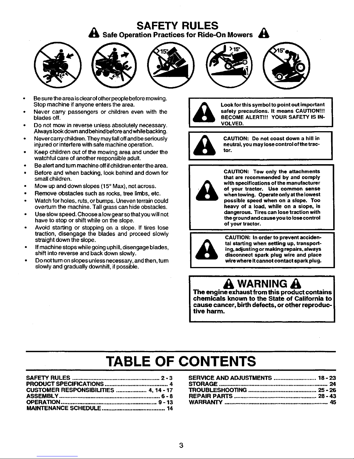
SAFETY RULES
Safe Operation Practices for Ride-On Mowers &
IMPORTANT: THIS CUTTING MACHINE IS CAPABLE OF AMPUTATING HANDS AND FEET AND THROWING OBJECTS.
FAILURE TO OBSERVE THE FOLLOWING SAFETY INSTRUCTIONS COULD RESULT IN SERIOUS INJURY OR DEATH.
L
Q
GENERAL OPERATION
Read, understand, and follow all i0structions in the
manual and on the machine before starting.
Only allow responsible adults,who arefamiliar withthe
instructions, to operate the machine.
Clear the area of objectssuchas rocks, toys, wire, etc.,
which could be picked up and thrown by the blade.
Be sure the area is clearofotherpeople before mowing.
Stop machine ifanyone enters the area.
Never carry passengers.
Do not mow in reverse unless absolutely necessary.
Always lookdownand behind beforeandwhile backing.
Be aware of the mower discharge direction and do not
point it at anyone. Do not operate the mower without
either the entire grass catcher orthe guard in place.
Slow down before turning.
Never leave a runningmachineunattended. Always turn
off blades, set parking brake, stopengine, and remove
keys before dismounting.
Turn off blades when not mowing.
Stop engine before removing grass catcher or unclog-
ging chute.
Mow only in daylight or good artificiallight.
Do not operate themachine whileunder the influance of
alcohol or drugs.
Watch for traffic when operating near orcrossing read-
ways.
Use extra care when loading or unloading the machine
into a trailer or truck.
Data indicates that operators,age 60 years and above,
are involved in a large percentage of riding mower-
related injuries. These operators should evaluate their
abiUty to operate the riding mower safely enough to
protect themselves and othersfrom sedous injury.
II. SLOPE OPERATION
Slopes are a major factor related to loss-of-control and
tipover accidents, which can resultinsevere injuryordeath.
All slopes require extra caution. If you cannot back up the
slope or if you feel uneasy on it, do not mow it.
DO:
• Mow up and down slopes, not across.
• Remove obstacles such as rocks, tree limbs, etc.
• Watch for holes, ruts,orbumps. Uneven terrain could
overturn the machine. Tal/ grass can hide obstacles.
• Uee slow speed. Choose a lowgear sothat you willnot
have to stop or shiftwhile on the slope.
• Follow the manufacturer's recommendations for wheel
weights or counterweights to improve stability.
• Use extra care with grass catchers or other attach-
ments. These can change the stabilityofthe machine.
• Keep all movement onthe slopesslowand gradual. Do
not make sudden changes in speed or direction.
• Avoid starting or stopping on a slope. If tires lose
traction, disengage the blades and proceed slowly
straight down the slope.
2
DO NOT:
• Do not turn on slopesunless necessary, and then, turn
slowlyand graduaUydownhill, ifpossible.
• Do not mow near drop-offs, ditches, or embankments.
The mower couldsuddenlyturnover ifa wheel isoverthe
edge of a cliff or ditch, or if an edge caves in.
Donotmow onwetgrass. Reduced traction could cause
slidir{g.
• Do not try to stabilizethe machine by putting your foot
onthe ground.
• Do not use grass catcher on steep slopes.
Ill. CHILDREN
Tragic accidents can occurif the operator is notalert to the
presence of children. Children are often attracted to the
machine and the mowing activity. Never assume that
childrenwill remain where you last saw them.
• Keep children out of the mowing area and Under the
watchfulcare of another responsible adult.
• Be alert and turnmachine off if children enter the area.
• Before and when backing, look behind and down for
small children.
• Nevercarrychildren. Theymayfalloffandbeseriously
injuredor interferewith safe machine operation.
• Never allow childrentooperate the machine.
• Use extra carewhen approaching blindcomers, shrubs,
trees, or other objects that may obscure vision.
IV. SERVICE
• Use extra care in handling gasoline and other fuels.
They are flammable and vapors are explosive.
Use only anapproved container.
Never remove gas cap or add fuel with the engine
running. Allowengine to cool before refueling, Do
not smoke.
Never refuelthe machine indoors.
Never store the machine or fuel container inside
where there isan open flame, suchas a water heater.
• Never run a machine inside a closed area.
• Keep nuts andbolts, especially blade attachment bolts,
tightand keep equipment in good condition.
• Nevertamperwithsafetydevices. Check their proper
operation regularly.
• Keep machine free of grass, leaves, or other debris
build-up. Cleanoilorfuelspinage. Allowmashinetocool
before stodng.
Stop and inspectthe equipment if you strike an object.
Repair, if necessary, before restarting.
• Never make adjustments or repairs with the engine
running.
• Grass catcher components are subject to wear, dam-
age, and detenoretion,whichcouldexpose moving parts
orallow objectstobe thrown. Frequently check compo-
nents and replace withmanufacturer's recommended
parts,when necessary.
• Mowerbladesaresharpandcancut. Wraptheblade(s)
or wear gloves, and use extra caution when servicing
them.
• Check brake operation frequently. Adjust and service
as required.
SAFETY RULES
& Safe Operation Practices for Ride-On Mowers &
Besure thearea is clear ofotherpeople beforemowing.
Stop machine if anyone enters the area.
• Never carry passengers or children even with the
blades off.
• Do not mow in reverse unless absolutely necessary.
Always lookdownand behindbeforeandwhilebacking.
• Never carry children. They mayfall offandbe seriously
injured or interfere withsafe machine operation.
• Keep children out of the mowing area and under the
watchful care of another responsible adult.
• Be alert and turn machine offif childrenenter the area.
• Before and when backing, look behind and down for
small children.
• Mow up and down slopes (15° Max), notacross.
• Remove obstacles such as rocks, tree limbs, etc.
• Watch for holes, ruts,orbumps. Uneven terrain could
overfurn the machine. Tall grass can hide obstacles.
• Use slowspeed. Choose a lowgear so thatyouwill not
have to stop or shift while on the slope.
• Avoid starting or stopping on a slope. If tires lose
traction, disengage the blades and proceed slowly
straight down the slope.
• If machine stops while goinguphill, disengage blades,
shift into reverse and back down slowly.
• Do not turn on slopesunlessnecessary, andthen, turn
slowly and gradually downhill,if possible.
Look for this symbol to point out important
safety precautions. It means CAUTION!!!
BECOME ALERT!!! YOUR SAFETY IS IN-
VOLVED.
CAUTION: Do not coast down a hill in
neutral, you may lose control of the trac-
tor.
CAUTION: Tow only the attachments
that are recommended by and comply
with specifications of the manufacturer
of your tractor. Use common sense
when towing. Operate only at the lowest
possible speed when on a slope. Too
heavy of a load, while on a slope, is
dangerous. Tires can lose traction with
the ground and cause you to lose control
of your tractor.
CAUTION: In order to prevent acciden-
tal starting when setting up, transport-
ing, adjusting or making repairs, always
disconnect spark plug wire and place
wire where it cannot contact spark plug.
I
L
& WARNING
The engine exhaust from this product contains
chemicals known to the State of California to
cause cancer, birth defects, or other reproduc-
tive harm.
TABLE OF CONTENTS
SAFETY RULES ...................................................... 2 - 3
PRODUCT SPECIFICATIONS ....................................... 4
CUSTOMER RESPONSIBILITIES ................... 4, 14- 17
ASSEMBLY .............................................................. 6 - 8
OPERATION ........................................................... 9 - 13
MAINTENANCE SCHEDULE ....................................... 14
SERVICE AND ADJUSTMENTS .......................... 18 - 23
STORAGE ................................................................... 24
TROUBLESHOOTING .......................................... 25 - 26
REPAIR PARTS ................................................... 28 - 43
WARRANTY ................................................................ 45
3
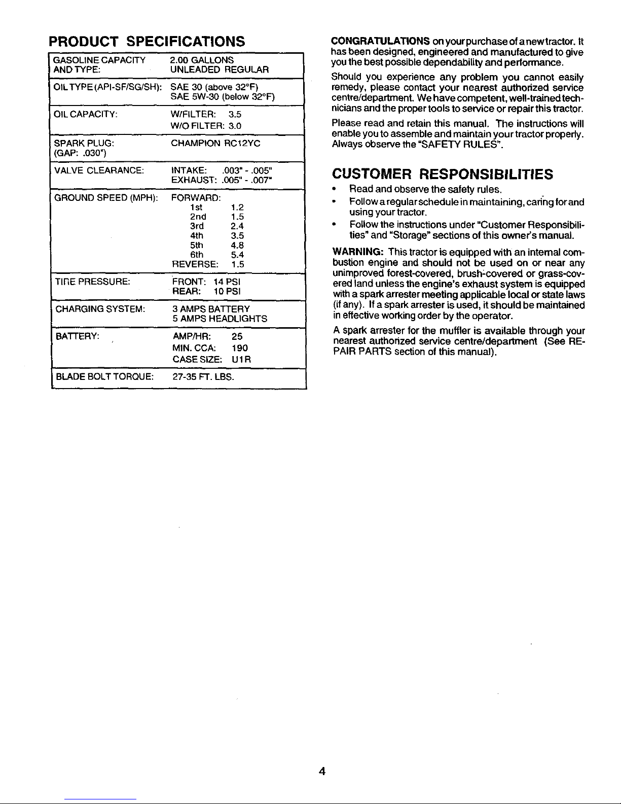
PRODUCT SPECIFICATIONS
GASOLINE CAPACITY 2.00 GALLONS
AND TYPE: UNLEADED REGULAR
OILTYPE(API-SF/SG/SH): SAE 30 (above 32°F)
SAE 5W-30 (below 32°F)
OILCAPACITY: W/FILTER: 3.5
W/O FILTER: 3.0
SPARKPLUG: CHAMPION RCI2YC
GAP: .030")
VALVE CLEARANCE: INTAKE: .003" -.005"
EXHAUST: .005" - ,007"
GROUND SPEED (MPH): FORWARD:
Ist 1.2
2nd 1.5
3rd 2.4
4th 3.5
5th 4.8
6th 5.4
REVERSE: 1.5
TIRE PRESSURE: FRONT: 14 PSI
REAR: 10 PSI
CHARGING SYSTEM: 3 AMPS BATTERY
5 AMPS HEADLIGHTS
BATTERY: AMPiHR: 25
MIN. CCA: 190
CASE SIZE: U 1R
BLADE BOLT TORQU E: 27-35 FT. LBS.
CONGRATULATIONS onyourpumhaseofanewtrector. It
has been designed, engineered and manufactured to give
you the best possibledependability and performance.
Should you experience any problem you cannot easily
remedy, please contact your nearest authorized service
centre/department We have competent, well-trained tech*
niciansand the proper toolsto service or repair this tractor.
Please read and retain this manual. The instructions will
enable you to assemble and maintain your tractor properly.
Always observe the =SAFETY RULES".
CUSTOMER RESPONSIBILITIES
• Read and observe the safety rules.
Followaregularschedule inmaintaining, cad-ngforand
using yourtractor.
• Follow the instructionsunder "Customer Responsibili-
ties"and "Storage" sections ofthis owner's manual
WARNING: This tractor is equipped with an internal com-
bustion engine and should not be used on or near any
unimproved forest-covered, brush:covered or grass-cov-
ered land unless the engine's exhaust system is equipped
witha spark arrester meeting applicable local or state laws
(ifany). If a spark arrester isused, itshould be maintained
ineffective workingorder by the operator.
A spark arrester for the muffler is available through your
nearest authorized service centre/department (See RE-
PAIR PARTS section ofthis manual).
4
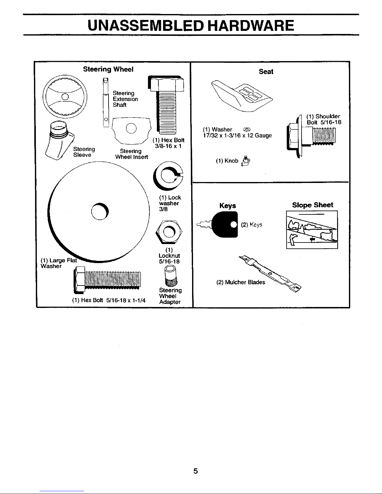
UNASSEMBLED HARDWARE
Steering Wheel
_Steedng
leeve
= Steering
Extension
Shaft
]L°-_ (1) Hex_Bolt
3/8-16 x 1
Steering
Wheel Insert
washer
3/8
Washer
_ Et
Steedng
Wheel
(1) Hex Bolt 5/16-18 x 1-1/4 Adapter
Seat
(1) Washer
17/32 x 1-3/16 x 12 Gauge
(1) Knob
(1) Shoulder
r_ Bolt 5/16-18
Keys
(2) KGys
Slope Sheet
(2) Mulch_
5
ASSEMBLY
Yournew tractorhas been assembled at the factory withexception of those parts leftunaseembled for shippingpurposes. To
ensure safe and proper operation of your tractor all parts and hardware you assemble must be tightened securely. Use the
correct tools as necessary to insure proper tightness.
TOOLS REQUIRED FOR ASSEMBLY
A socket wrench set will make assembly easier. Standard
wrench sizes are listed.
(2) 1/2" wrenches Utility knife
(2) 9/16" wrench Tirepressuregauge
Phillipsscrewdriver
When rightor lefthand ismentioned inthis manual, it means
when you are in the operating position (seated behind the
steering wheel).
TO REMOVE TRACTOR FROM CARTON
UNPACK CARTON
• Remove all accessible loose parts and parts cartons
from carton.
• Cut, from top to bottom, along lines on all four corners
of carton, and lay panels flat.
• Check for any additional loose parts or cartons and
remove.
BEFORE REMOVING TRACTOR FROM
SKID
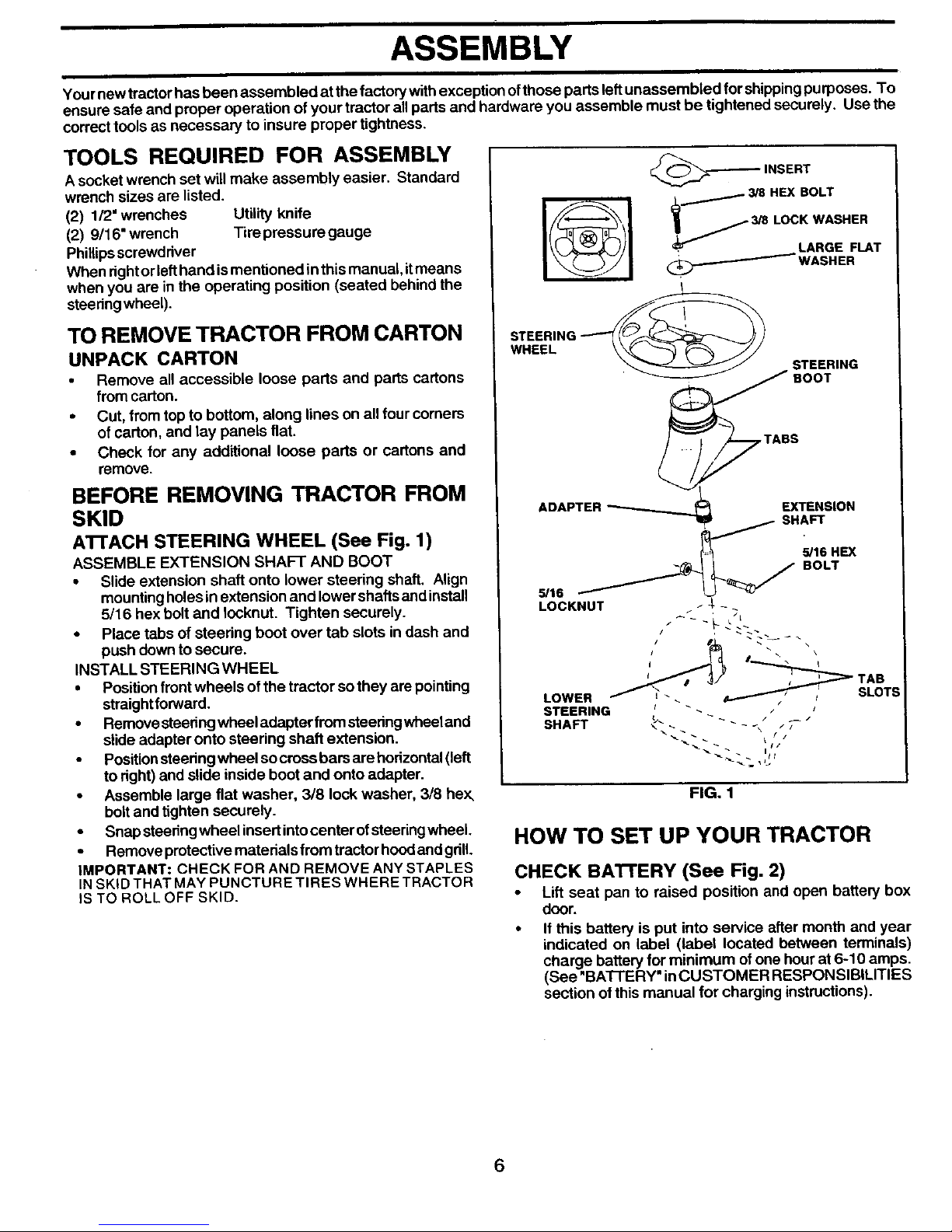
AI-rACH STEERING WHEEL (See Fig. 1)
ASSEMBLE EXTENSION SHAFT AND BOOT
• Slide extension shaft onto lower steering shaft. Align
mounting holes in extension and lower shafts and install
5/16 hex bolt and Iocknut. Tighten securely.
• Place tabs of steering boot over tab slots in dash and
push down to secure.
INSTALL STEERING WHEEL
• Position front wheels of the tractor so they are pointing
straightforward.
• Remove steedngwheel adapter fromsteedngwheeland
slide adapter onto steering shaft extension.
• Positionsteeringwheel so cross bars are horizontal(left
to right) and slide inside boot and onto adapter.
• Assemble large flat washer, 318 lock washer, 318 hex,
boltand tighten securely.
• Snap steeringwheelinsert intocenter ofstseringwheel.
• Remove protective materials from tractor hood and gdlL
IMPORTANT: CHECK FOR AND REMOVE ANY STAPLES
INSKID THAT MAY PUNCTURE TIRES WHERE TRACTOR
IS TO ROLL OFF SKID.
,_-_ INSERT
• / 3/8 HEX BOLT
_ 3/8 LOCK WASHER
, LARGE FLAT
(_.._ WASHER
STEERING __
WHEEL
STEERING
'_ BOOT
.__TABS
ADAPTER _ EXTENSION
SHAFT
,OH X
S,'16 _ BOLT
LOCKNUT / J_- -
LOWER / _'. _ _' SLOT:
STEERING _ _ _ _
SHAFT _" - - _ --
FIG. 1
HOW TO SET UP YOUR TRACTOR
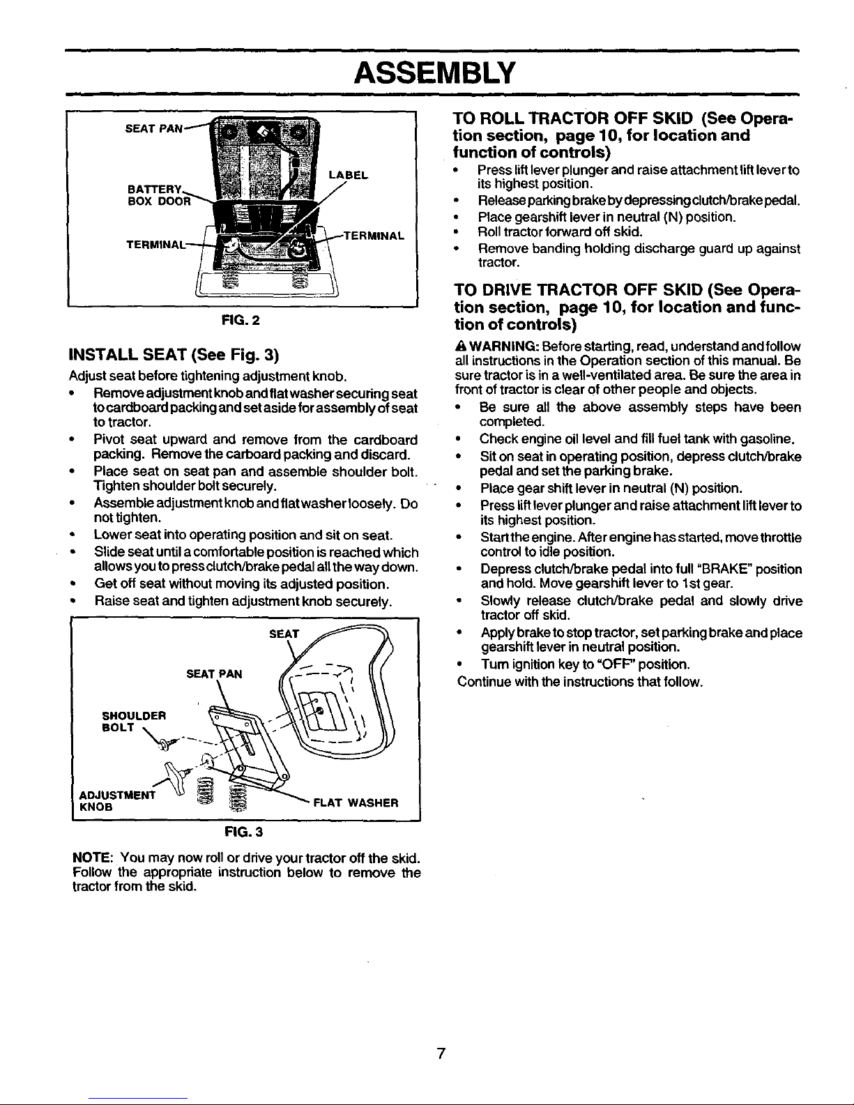
CHECK BA'FI'ERY (See Fig. 2)
• Lift seat pan to raised position and open battery box
door.
• If this battery is put into service after month and year
indicated on label (label located between terminals)
charge battery for minimum of one hour at 6-10 amps.
(See "BA'I-I'ERY" inCUSTOMER RESPONSIBILITIES
section of this manual for charging instructions).
6
ASSEMBLY
BATTERY
BOX
LABEL
FIG. 2
INSTALL SEAT (See Fig. 3)
Adjustseat before tighteningadjustment knob.
• Remove adjustment knoband fiatwasher securing seat
tocardboard packingand set aside forassembly of seat
totractor.
• Pivot seat upward and remove from the cardboard
packing. Remove the carboard packing and discard.
• Place seat on seat pan and assemble shoulder bolt.
Tighten shoulder bolt securely.
• Assembleadjustmentknobandflatwasherloosely. Do
not tighten.
• Lower seat into operating position and sit on seat.
• Slide seat until a comfortable position is reached which
allows you to press clutch/brake pedal all the way down.
• Get oft seat without moving its adjusted position.
• Raise seat and tighten adjustment knob securely.
i
SHOULDER
BOLT _.__ .
ADJUSTMENT '_
KNOB
SEAT PAN SE_
i _ FLAT WASHER
FIG. 3
NOTE: You may now rollor driveyour tractor off the skid.
Follow the appropriate instruction below to remove the
tractor from the skid.
TO ROLL TRACTOR OFF SKID (See Opera-
tion section, page 10, for location and
function of controls)
• Press lift lever plunger and raise attachment lift lever to
its highest position.
• Release parking brake by depressing clutch/brake pedal.
• Place gearshift lever in neutral (N) position.
• Roll tractor forward off skid.
• Remove banding holding discharge guard up against
tractor.
TO DRIVE TRACTOR OFF SKID (See Opera-
tion section, page 10, for location and func-
tion of controls)
WARNING: Before starting, read, understand and follow
all instructionsin the Operation section of this manual. Be
sure tractor is in a well-ventilated area. Be sure the area in
front of tractor is clear of other people and objects.
• Be sure all the above assembly steps have been
completed.
• Check engine oillevel and fill fuel tank with gasoline.
• Sit on seat in operating position, depress clutch/brake
pedal and set the parking brake.
• Place gear shift lever in neutral (N) position.
• Press liftlever plunger and raise attachment liftlever to
its highest position.
• Startthe engine. After engine hasstarted, movethrottle
controlto idle position.
• Depress clutch/brake pedal intofull "BRAKE" position
and hold. Move gearshift lever to 1st gear.
• Slowly release clutch/brake pedal and slowly drive
tractor off skid.
• Applybraketostoptractor, set parking brake and place
gearshift lever in neutral position.
• Turn ignitionkey to"OFF" position.
Continue withthe instructionsthat follow.
7
ASSEMBLY
CHECK TIRE PRESSURE
IMPORTANT: FOR SHIPPING PURPOSES, THE
MULCHER PLATE WAS PREATTACHED TO YOUR
MOWER. THE MULCHER PLATE MUST ONLY BE USED
WITH THE MULCHING BLADES THAT CAME PACKED
SEPARATELY IN THE CARTON.
YOUR MOWER CAME FACTORY EQUIPPED WITH HIGH
PERFORMANCE BLADES, WHICH ARE THE BEST
BLADES FOR BAGGING AND DISCHARGING. TO USE
YOUR MOWER WITH THE HIGH PERFORMANCE BLADES
THE MULCHER PLATE MUST BE REMOVED FROM THE
MOWER (SEE FIG. 4).
TO SET UP YOUR MOWER FOR MULCHING
• Remove high performance blades and install mulcher
blades, (see BLADE REMOVAL in the CUSTOMER
RESPONSABILITY section of this manual).
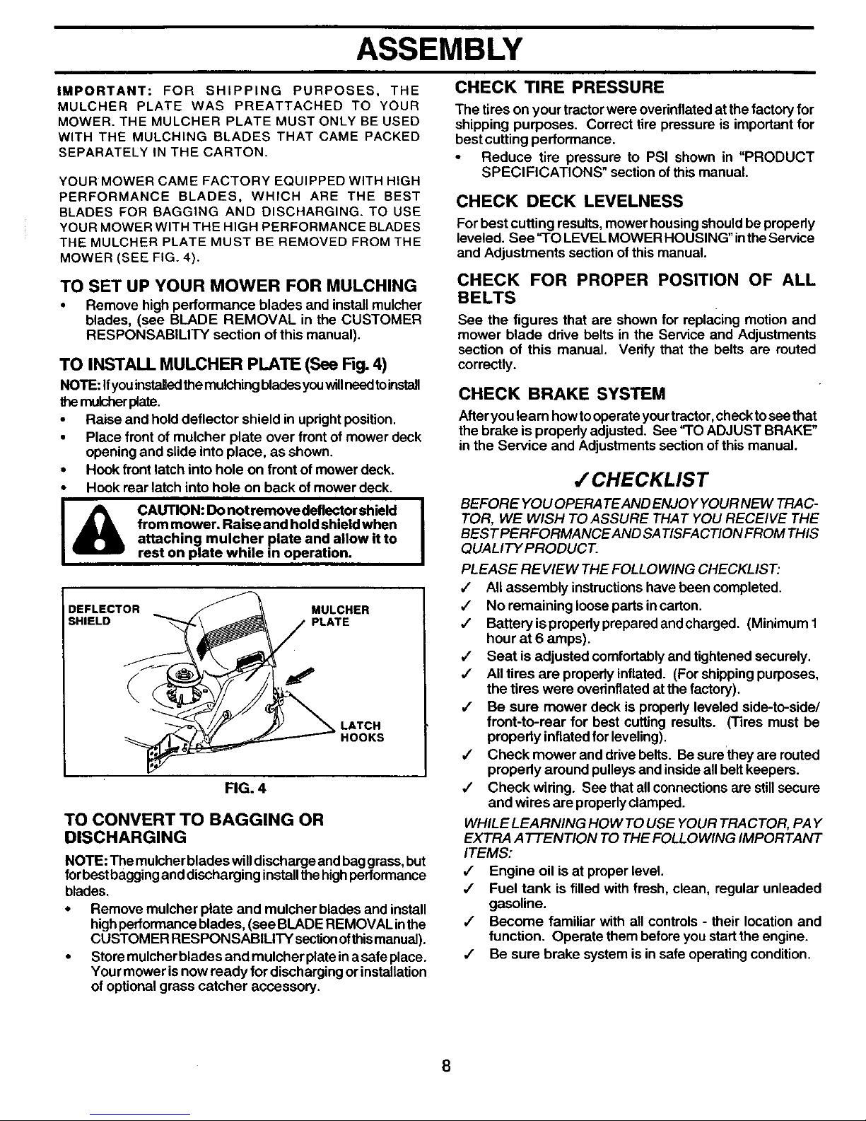
TO INSTALL MULCHER PLATE (See Fig. 4)
NOTE: Ifyou installedthemulching bladesyouwillneedtoinstall
themulsher plate.
• Raise and hold deflector shield in upright position.
• Place front of mulcher plate over front of mower deck
opening and slide into place, as shown.
• Hook front latch into hole on front of mower deck.
• Hook rear latch into hole on back of mower deck.
I& AUTION: Do not remove deflector shield I
from mower. Raise and hold shield when
attaching mulcher plate and allow it to
rest on plate while in operation.
DEFLECTOR MULCHER
SHIELD PLATE
LATCH
HOOKS
FIG. 4
TO CONVERT TO BAGGING OR
DISCHARGING
NOTE: The mulcherblades willdischarge and baggrass, but
forbest bagginganddischarging installthe highperformance
blades.
• Remove mulcher plate and mulcher blades and install
highperformance blades, (see BLADE REMOVAL inthe
CUSTOMER RESPONSABILITY secl_onofthis manual).
• Store mulcher blades and mulcher plate ina safe place.
Your mower is now ready for discharging or installation
of optional grass catcher accessory.
The tires on your tractor were overinflated at the factory for
shipping purposes. Correct tire pressure is important for
best cutting performance.
• Reduce tire pressure to PSI shown in "PRODUCT
SPECl FICATIONS" section of this manual.
CHECK DECK LEVELNESS
For best cutting results, mower housingshould be propedy
leveled. See "TO LEVEL MOWER HOUSING" inthe Service
and Adjustments section of this manual.
CHECK FOR PROPER POSITION OF ALL
BELTS
See the figures that are shown for replacing motion and
mower blade ddve belts in the Service and Adjustments
section of this manual. Verify that the belts are routed
correctly.
CHECK BRAKE SYSTEM
Afteryou learn howtooperate yourtractor, checktosee that
the brake is prepedy adjusted. See "TO ADJUST BRAKE"
in the Service and Adjustments sectionof this manual.
/ CHECKLIST
BEFORE YOU OPERA TE AND ENJOY YOUR NEW TRAC-
TOR, WE WISH TO ASSURE THAT YOU RECEIVE THE
BESTPERFORMANCEAND SA TISFACTION FROM THIS
QUALITY PRODUCT.
PLEASE REVIEW THE FOLLOWING CHECKLIST:
,/ Allassembly instructionshave been completed.
4 No remaining loose parts incarton.
•/ Battery ispropedy prepared andcharged. (Minimum 1
hour at 6 amps).
4" Seat is adjusted comfortably and tightened securely.
•/ All tires are propedy inflated. (For shipping purposes,
the tires were ovednflated at the factory).
,/ Be sure mower deck is propedy leveled side-to-side/
front-to-rear for best cuffing results. (Tires must be
properly inflated for leveling).
,/ Check mower and drivebelts. Be surethey are routed
propedy around pulleys and insideallbeltkeepers.
,/ Check widng. See that allconnectionsare stillsecure
and wires are properlyclamped.
WHILE LEARNING HOW TO USE YOUR TRACTOR, PAY
EXTRA ATTENTION TO THE FOLLOWING IMPORTANT
ITEMS:
,f Engine oil is at proper level.
,/ Fuel tank is filled with fresh, clean, regular unleaded
gasoline.
,/ Become familiar with all controls - their location and
function. Operate them before you start the engine.
J Be sure brake system is in safe operating condition.
8
OPERATION
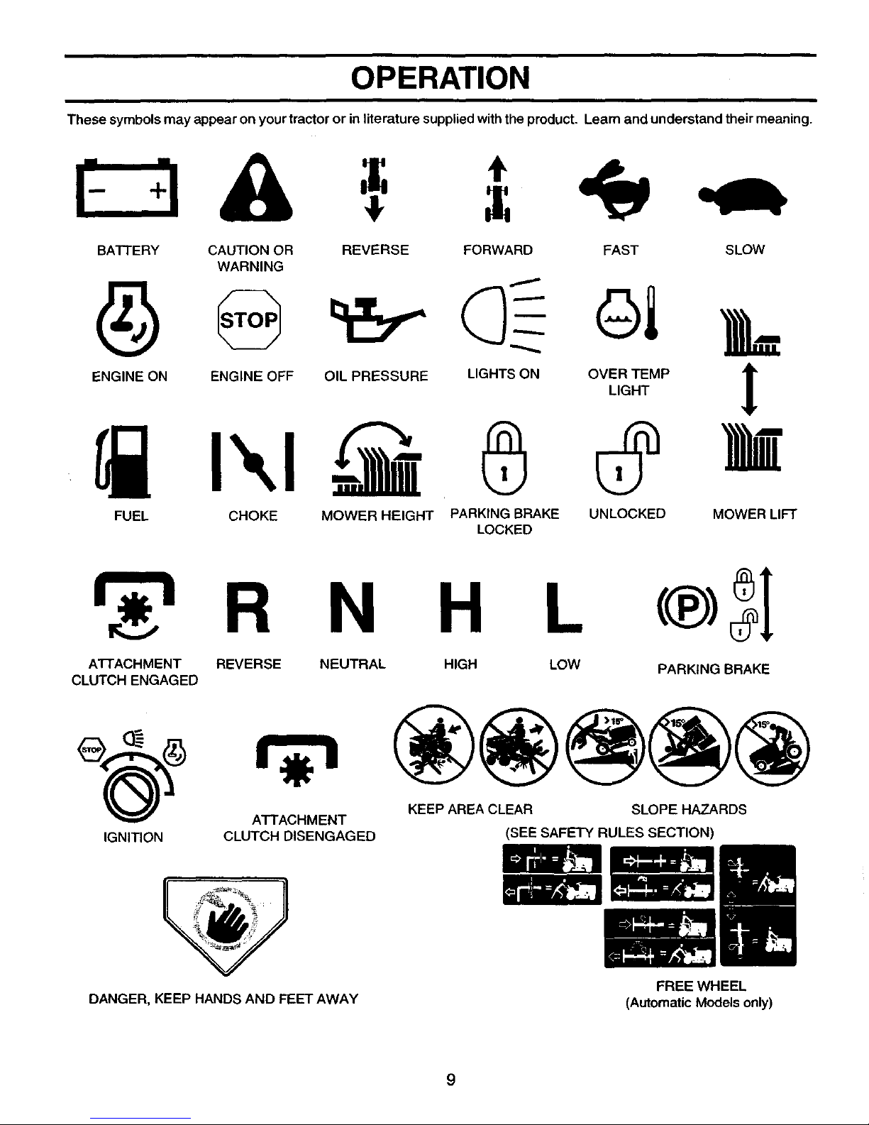
These symbols may appear on yourtractor or in literature supplied with the product. Learn and understand their meaning.
I- qA
BATTERY CAUTION OR REVERSE FORWARD FAST SLOW
WARNING
,L
ENGINE ON ENGINE OFF OIL PRESSURE LIGHTS ON OVER TEMP lr
LIGHT
!
FUEL CHOKE MOWER HEIGHT PARKING BRAKE UNLOCKED MOWER LIFT
LOCKED
r -i R N H L
ATTACHMENT REVERSE
CLUTCH ENGAGED
NEUTRAL HIGH LOW
PARKING BRAKE
KEEP AREA CLEAR SLOPE HAZARDS
ATTACHMENT
IGNITION CLUTCH DISENGAGED (SEE SAFETY RULES SECTION)
DANGER, KEEP HANDS AND FEET AWAY
FREE WHEEL
(Automatic Models only)
9

OPERATION
KNOW YOUR TRACTOR
READ THIS OWNER'S MANUAL AND SAFETY RULES BEFORE OPERATING YOUR TRACTOR
Compare the illustrations with your tractor tofamiliarize yourself withthe locations ofvariouscontrolsand adjustments. Save
thismanual for future reference.
ATTACHMENT
CLUTCH LEVER
IGNITION
SWITCH LIGHT SWITCH
AMMETER
THROTTL_ LIFT LEVER
CHOKE PLUNGER
CONTROL
ATTACHMENT
UFTLEVER
HEIGHT
ADJUSTMENT
KNOB
GEAR SHIFT
LEVER
PARKING
BRAKE
FIG. 5
Our tractors conform to the safety standards ofthe American National Standards Institute.
ATTACHMENT CLUTCH LEVER: Used to engage the
mowerblades, orother attachments mountedtoyourtractor.
UGHT SWITCH: Turns the headlights on and off.
THROTTLE/CHOKE CONTROL: Used for starting and
controllingengine speed.
CLUTCH/BRAKE PEDAL: Used for declutchingand brak-
ingthe tractor and starting the engine.
PARKING BRAKE: Locks clutch/brake pedalintothe brake
position.
HEIGHT ADJUSTMENT KNOB - Used toadjustthe mower
cutting height.
GEARSHIFT LEVER - Selects the speed and direction of
the tractor.
ATTACHMENT LIFT LEVER: Used to raise, lower, and
adjustthe mower deck orotherattachments mountedtoyour
tractor.
LIFT LEVER PLUNGER: Used to release attachment lift
lever when changing itsposition.
IGNITION SWITCH: Used for starting and stopping the
engine.
AMMETER - Indicates charging (+) or discharging (-) of
battery.
10
OPERATION
I
The operation ofany tractor can result inforeign objects thrown into the eyes, which can
result in severe eye damage. Always wear safety glasses or eye shields while operating
your tractor or performing any adjustments or repairs. We recommend a wide vision
safety mask over spectacles or standard safety glasses.
I
HOW TO USE YOUR TRACTOR
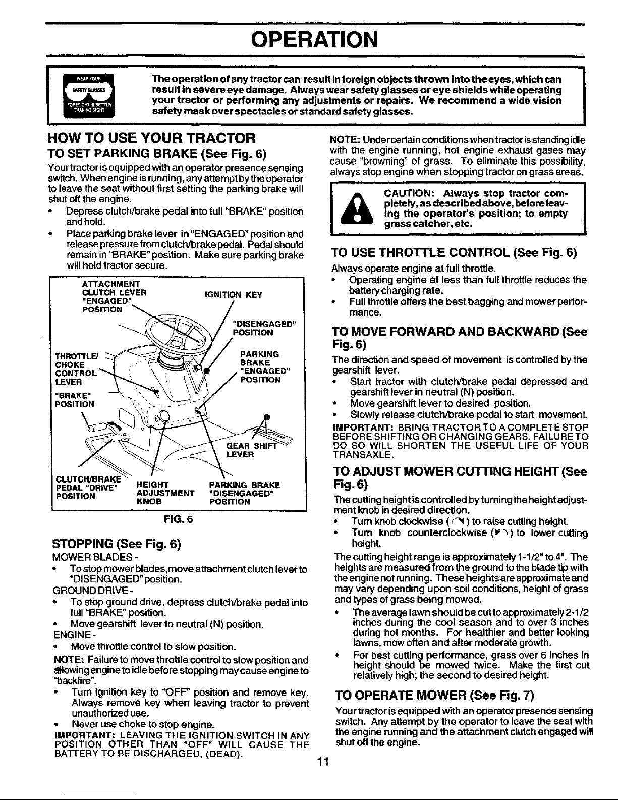
TO SET PARKING BRAKE (See Fig. 6)
Yourtractorisequipped with an operator presence sensing
switch.When engine isrunning, any attemptbytheoperator
to leave the seat without first setting the parking brake will
shut offthe engine.
• Depress clutch/brake pedal intofull "BRAKE" position
and hold.
• Place parkingbrake lever in"ENGAGED" position and
release pressurefromclutch/brake pedal Pedal should
remain in"BRAKE" position. Make sure parking brake
willholdtractor secure.
I
ATTACHMENT
CLUTCH LEVER
"ENGAGED"
POSITION
IGNITION KEY
"DISENGAGED"
POSITION
THRO'n'LE/
PARKING
BRAKE
"ENGAGED"
POSITION
LEVER
PEDAL "DRIVE" HEIGHT PARKING BRAKE
POSITION ADJUSTMENT "DISENGAGED"
KNOB POSITION
FIG. 6
STOPPING (See Fig. 6)
MOWER BLADES -
• To stop mower blades,move attachment clutch lever to
"DISENGAGED" position.
GROUND DRIVE-
• To stop ground drive, depress clutch/brake pedal into
full "BRAKE" position.
• Move gearshift lever to neutral (N) position.
ENGINE -
• Move throttle controlto slow position.
NOTE: Failure to move throttle controlto slow positionand
eNowingenginetoidle before stopping may cause engine to
"backfire".
• Turn ignition key to "OFF" position and remove key.
Always remove key when leaving tractor to prevent
unauthorized use.
Never use choke to stop engine.
IMPORTANT: LEAVING THE IGNITION SWITCH IN ANY
POSITION OTHER THAN "OFF" WILL CAUSE THE
BATTERY TO BE DISCHARGED, (DEAD).
NOTE: Under certain conditions when tractor isstanding idle
with the engine running, hot engine exhaust gases may
cause "browning" of grass. To eliminate this possibility,
always stop engine when stopping tractor ongrass areas.
&
|
CAUTION: Always stop tractor com- |
pletety, as described above, before leav-
I
ing the operator's position; to empty
grass catcher, etc.
TO USE THRO'n'LE CONTROL (See Fig. 6)
Always operate engine at fullthrottle.
Operating engine at less than full throttlereduces the
battery charging rate.
• Full throttle offers the best bagging and mower perfor-
mance.
TO MOVE FORWARD AND BACKWARD (See
Fig. 6)
The direction and speed of movement is controlledby the
gearshift lever.
• Start tractor with clutch/brake pedal depressed and
gearshift lever in neutral (N) position.
• Move gearehiff lever to desired position.
Slowly release clutch/brake pedal to start movement.
IMPORTANT: BRING TRACTOR TO A COMPLETE STOP
BEFORE SHIFTING OR CHANGING GEARS. FAILURE TO
DO SO WILL SHORTEN THE USEFUL LIFE OF YOUR
TRANSAXLE.
TO ADJUST MOWER CU'I-rlNG HEIGHT (See
Fig. 6)
The cuttingheightis controlled by turningthe heightadjust-
ment knob in desired direction.
• Turn knobclockwise ((-_) to raise cutting height.
• Turn knob counterclockwise (1_-_)to lower cutting
height.
The cutting height range is approximately 1-1/2" to 4". The
heights are measured from the ground totheblade tipwith
theenginenotrunning. These heights areapproximateand
may vary depending upon soil conditions, height of grass
and types ofgrass being mowed.
• The average lawn should be cutto approximately2-1/2
inches during the cool season and to over 3 inches
during hot months. For healthier and better looking
lawns, mow often and after moderate growth.
• For best cutting performance, grass over S inches in
height should be mowed twice. Make the first cut
relatively high; the second to desired height.
TO OPERATE MOWER (See Fig. 7)
Yourtractor isequipped with an operator presence sensing
switch. Any attempt by the operator to leave the seat with
the engine running and the attachment clutchengaged will
shut off the engine.
11
OPERATION
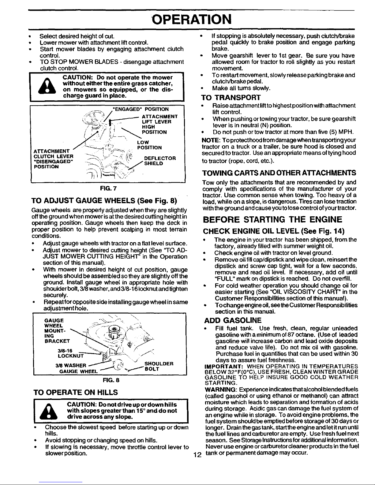
• Select desired height ofcut.
• Lower mower with attachment lift control.
• Start mower blades by engaging attachment clutch
control
• TO STOP MOWER BLADES - disengage attachment
clutch control.
A
CAUTION: Do not operate the mower
without either the entire grass catcher,
on mowers so equipped, or the dis-
charge guard in place.
ATTACHMENT
CLUTCH LEVER -_
"DISENGAGED = -->_
POSITION
'ENGAGED" POSITION
ATTACHMENT
LIFT LEVER
HIGH
i',! _ POSITION
POSITION
7;
DEFLECTOR
FIG. 7
TO ADJUST GAUGE WHEELS (See Fig. 8)
Gauge wheels are properlyadjusted when they are slightly
offthe ground when mower isat the desired cuttingheight in
operating position. Gauge wheels then keep the deck in
proper position to help prevent scalping in most terrain
conditions.
• Adjust gauge wheels with tractor on a flat level surface.
• Adjust mower to desired cutting height (See "1"O AD-
JUST MOWER CU'I-FING HEIGHT" in the Operation
section of this manual).
• With mower in desired height of cut position, gauge
wheels should be assembled so they are slightly off the
ground. Install gauge wheel in appropdate hole with
shoulder bolt, 3/8 washer, and 3/8-16 Iocknut and tighten
securely.
• Repeat for opposite side installing gauge wheel in same
adjustment hole.
GAUGE -- "'_
WHEEL . .,:_,\
MOUNT-
ING
BRACKET
3/8-16
LOCKNUT J:_
3/S WASHER SHOULDER
GAUGE WHEEL
FIG. 8
TO OPERATE ON HILLS
I & CAUTION: Donotdriveupordownhills I
with slopes greater than 15° and do not
drive across any slope.
• Choose the slowest speed before starting up or down
hills.
• Avoid stopping or changing speed on hills.
• If slowing is necessary, move throttle control lever to
slower position.
• If stopping is absolutely necessary, push clutch/brake
pedal quickly to brake position and engage parking
brake.
• Move gearshift lever to 1st gear. Be sure you have
allowed room for tractor to roll slightly as you restart
movement.
• To restart movement, slowly release parking brake and
clutch/brake pedal.
• Make all turns slowly.
TO TRANSPORT
• Raise attachment liftto highest position with attachment
lift control.
• When pushing or towing your tractor, be sure gearshift
lever is in neutral (N) position.
• Do not push or tow tractor at more than five (5) M PH.
NOTE: To protect hood from damage when transporting your
tractor on a truck or a trailer, be sure hood is closed and
secured to tractor. Use an appropriate means of tyinghood
to tractor (rope, cord, etc.).
TOWING CARTS AND OTHER ATrACHMENTS
Tow only the attachments that are recommended by and
comply with specifications of the manufacturer of your
tractor. Use common sense when towing. Too heavy of a
load, while on a slope, is dangerous. Tires can lose traction
with the ground and cause you to lose control of you rtractor.
BEFORE STARTING THE ENGINE
12
CHECK ENGINE OIL LEVEL (See Fig. 14)
• The engine in yourtractor has been shipped, fromthe
factory, already filled withsummer weight oil.
• Check engine oilwithtractoron level ground.
• Remove oilfillcap/dipstickand wipe clean, reinsert the
dipstick and screw cap tight, wait for a few seconds,
remove and read oil level. If necessary, add oil until
"FULL" mark ondipstick is reached. Do not overfill.
, For cold weather operation you should change oil for
easier starting (See "OIL VISCOSITY CHART" inthe
Customer Responsibilitiessection of this manual).
• To change engineoil,seetheCustomer Reaponsibilities
section in this manual.
ADD GASOLINE
• Fill fuel tank. Use fresh, clean, regular unleaded
gasoline with a minimum of87 octane. (Use of leaded
gasoline willincrease carbon and lead oxide deposits
and reduce valve life). Do not mix oil with gasoline.
Purchase fuel in quantities that can be used within 30
days to assure fuel freshness.
IMPORTANT: WHEN OPERATING IN TEMPERATURES
BELOW 32°F(0°C), USE FRESH, CLEAN WINTER GRADE
GASOLINE TO HELP INSURE GOOD COLD WEATHER
STARTING.
WARNING: Experience indicatesthatalcoholblendedfuels
(called gasohol or using ethanol or methanol) can attract
moisture Which leads to separation and formation of acids
during storage. Acidic gas can damage the fuel system of
an engine while in storage. To avoid engine problems, the
fuel system should be emptied before storage of 30 days or
longer. Drain the gas tank, start the engine and let it run until
the fuel lines and carburetorareempty. Use fresh fuel next
season. See Storage Instructionsfor additionalinformation.
Never use engine orcarburetor cleaner products in the fuel
tank or permanent damage may occur.
OPERATION
I
&
CAUTION: Fill to bottom of gas tank J "
filler neck. Do not overfill. Wipe off any
I
spilled oil or fuel. Do not store, spill or
use gasoline near an open flame. •
TO START ENGINE (See Fig. 6)
When startingthe engine forthe firettime or ifthe engine has
run out of fuel, it will take extra cranking time to move fuel
from the tank to the engine.
• Sit on seat in operating position, depress clutch/brake
pedal and set parking brake.
• Place gear shift lever in neutral (N) position.
• Move attachment clutch to "DISENGAGED" position.
• Move throttle control to choke gkl) position.
NOTE: Before starting, read the warm and cold starting
procedures below.
• Insert key into ignition and turn key clockwise to
"START' position and release key as soon as engine
starts. Do not run starter continuously for more than
fifteen seconds per minute. If the engine does not start
after several attempts, move throttle control to fast
position, wait a few minutes and try again. If engine still
does not start, move the throttle control back to the
choke (1\1)position and retry.
WARM WEATHER STARTING (50 ° F and above)
When engine starts, move the throttle control tothe fast
position.
• The attachments and ground drive can now be used. If
the engine does not accept the load, restart the engine
and allow it to warm up for one minute using the choke
as described above.
COLD WEATHER STARTING ( 50 ° F and below)
• When engine starts, allow engine to run withthe throttle
control in the choke (1\1)position until the engine runs
roughly, then move throttle control to fast position. This
may require an engine warm-up period from several
seconds to several minutes, depending on the tempera-
ture.
• The attachments can also be used during the engine
warm-up pedod.
NOTE: If at a high altitude (above 3000 feet) or in cold
temperatures (below 32 F) the carburetor fuel mixture may
need to be adjusted for best engine performance. See "TO
ADJUST CARBURETOR" in the Service and Adjustments
section of this manual.
MOWING TIPS
Mower should be properly leveled for best mowing
performance. See "TO LEVEL MOWER HOUSING" in
the Service and Adjustments section of this manual,
The left hand sideof mower shouldbe usedfortrimming.
Drive sothat clippingsare discharged onto thearea that
has been cut. Have the cut area to the right of the
machine. This will result in a more even distributionof
clippings and more uniform cutting.
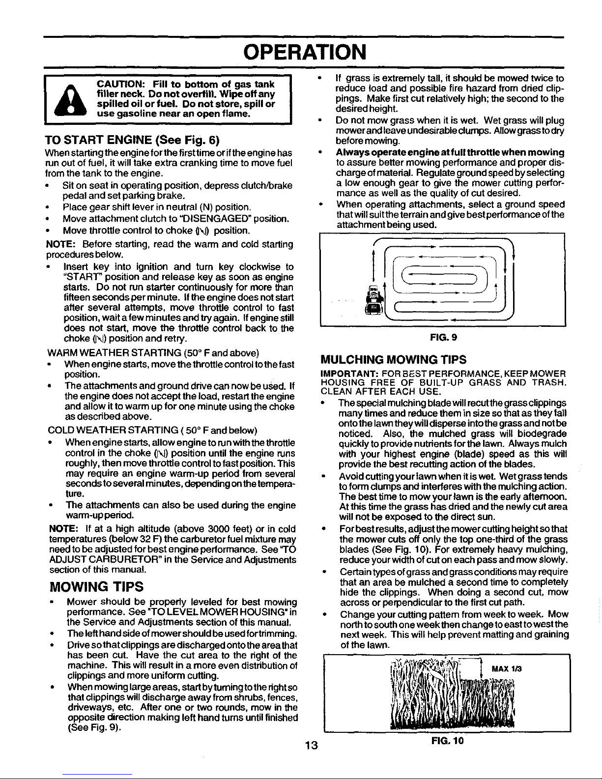
When mowing large areas, start bytuming to therightso
that clippings willdischarge away from shrubs,fences,
driveways, etc. After one or two rounds, mew in the
opposite direction making left hand turns untilfinished
(See Fig. 9).
If grass is extremely tall, it should be mowed twice to
reduce load and possible fire hazard from dried clip-
pings. Make first cut relatively high; the second to the
desired height.
Do not mow grass when it is wet. Wet grass will plug
mower and leave undesirable clumps. Allowgrass to dry
before mowing.
Always operate engine at full throttle when mowing
to assure better mowing performance and proper dis-
charge of material. Regulate groundspeed by selecting
a low enough gear to give the mower cutting perfor-
mance as well as the quality ofcut desired.
When operating attachments, select a ground speed
thatwillsuittheterrain and give best performance ofthe
attachment being used.
f
T
(
.i
FIG. 9
MULCHING MOWING TIPS
IMPORTANT: FOR BEST PERFORMANCE, KEEP MOWER
HOUSING FREE OF BUILT-UP GRASS AND TRASH.
CLEAN AFTER EACH USE.
• The special mulchingblade willrecutthe grassclippings
many times and reduce them in size sothatas they fall
ontothe lawntheywilldisperse intothegrassand notbe
noticed. Also, the mulched grass will biodegrade
quickly to provide nutrientsfor the lawn. Always mulch
with your highest engine (blade) speed as this will
provide the best recutting action ofthe blades.
• Avoid cuffingyour lawn when itiswet. Wet grasstends
toform clumps and interferes with the mulchingaction.
The best time to mow your lawn is the eady afternoon.
Atthis time the grass has dried and thenewly cut area
will not be exposed to the direct sun.
• For best results,adjust the mower cuttingheight sothat
the mower cuts off only the top one-third of the grass
blades (See Fig. 10). For extremely heavy mulching,
reduce your widthof cut on each pass and mow slowly.
• Certain types ofgrass and grass conditionsmay require
that an area be mulched a second time to completely
hide the clippings. When doing a second cut, mow
across or perpendicular to the first cutpath.
• Change your cutting pattern from week to week. Mow
northtosouthone week then change toeastto westthe
next week. This willhelp prevent matting and graining
ofthe lawn.
I! _ '. ,,,tI l
,'.! :
13 FIG. 10

CUSTOMER RESPONSIBILITIES
FILL IN DATES
AS YOU COMPLETE , _ _'_ 9,_
Y_,_._/'e_" SERVICE DATES
C ckBr.eo.ra.nW
Check Tire Pressure
Check Operator Presence and
T !Interlock Systems I_
R!C"e for Loose Fasteners I_ I_? V _
A
Sharpen/Replace Mower Blades I_.
C Lubrication Chart V _
O Check Battery Level
Clean Battery and Terminals !_
Check Transaxle Cooling V'
Adjust Blade Bait(s)Tension VPs
Adjust Motion Drive Belt(s) Tension I I_s [
Check Engine Oil Level i I_ ll_
Change Engine Oil _i 3
Clean Air Filter
Clean Air Screen
Inspect Muffler/Spark An'ester
Reptace Oil Filter (if equipped) li_12
Clean Engine Cooling Fins i_ 2
Replace Spark Plug Ik_
Replace Air Filter Paper Cartridge 11_2
Replace Fuel Filter li/
1 -Changemoreonenwhenoperalingunderaheavyioadorinhighambientte_ms. 5-#eq_pt0edv._hadiustablesystem.
2 - Service rnom often when operatingin didy or dusty cold,ions. 6 - NOt requitedif equipped with maintenance-free batte_.
3 - If equipped with Oilfilter, change Oileve_ 50 hours. 7 - T_hten fiont axle pivot bolt to 35 ft.4bs, maximum.
4 - Replace bk_les moreoften when mow_g in sandy soil. DOnot overl_hten.
GENERAL RECOMMENDATIONS
The warranty on thistractordoes not cover items that have
been subjected tooperator abuse ornegligence. To receive
fullvalue from the warranty, operator must maintain tracto_
as instructed in this manual.
Some adjustments will need to be made periodically to
propedy maintain your tractor.
Alladjustments in the Service and Adjustments section of
this manual should be checked at leastonce each season.
• Once a yearyou should replace the spark plug, clean or
replace eir filter,andcheck bladesandbelts for wear. A
new spark plug andclean airfilterassure proper air-fuel
mixture and help yourengine runbetter and lastlonger.
BEFORE EACH USE
• Check engine oil level.
• Check brake operation.
• Check tirepressure.
• Check operator presence and
interlock systems for proper operation.
Check for loose fasteners.
(_)SPINDLE
(_ FRONT
BEARING
ZERK
LUBRICATION CHART
•FRONT WHEEL(_
L- BEARING ZERK
GEARSHIFT_)
"r- ) PIVOTSI
I I
1_ SAE 30 OR 10W30 MOTOR OIL
(_) GENERAL PURPOSE GREASE
(_)REFER TO CUSTOMER
RESPONSIBILITIES
"ENGINE"
SECTION
IMPORTANT: DO NOT OIL OR GREASE THE PIVOT POINTS
WHICH HAVE SPECIAL NYLON BEARINGS. VISCOUS LUBRI-
CANTS WILL ATTRACT DUST AND DIRT THAT WILL SHORTEN
THE LIFE OF THE SELF-LUBRICATING BEARINGS. IF YOU
FEEL THEY MUST BE LUBRICATED, USE ONLY A DRY, POW-
14 DERED GRAPHITE TYPE LUBRICANT SPARINGLY.
CUSTOMER RESPONSIBILITIES
TRACTOR
Always observe safety rules when performing any mainte-
nance.
BRAKE OPERATION
Iftractor requires more than six (6) feet stoppingdistance at
high speed in highest gear, then brake must be adjusted.
(See =TOADJUST BRAKE" inthe Service andAdjustments
section of this manual).
TIRES
• Maintainproperairpressureinalltires(See=PRODUCT
SPECIFICATIONS" section of this manual).
• Keep tires free ofgasoline, oil, or insectcontrolchemi-
cals which can harm rubber.
• Avoid stumps, stones, deep ruts, sharp objects and
other hazards that may cause tire damage.
NOTE: To seal tire punctures and prevent flat tires due to
slow leaks, tire sealant may be purchased from your local
parts dealer. Tire sealant also prevents tire dry rot and
corrosion.
OPERATOR PRESENCE SYSTEM
Besure operator presence and interlocksystems are work-
ing properly. If your tractor does not function as described,
repairthe problem immediately.
• The engine should not start unless the clutch/brake
pedal is fully depressed and attachement clutchcontrol
is in the disengaged position.
• When the engine isrunning, any attemptbythe operator
to leave the seat without first settingthe parking brake
should shut off the engine.
• When theengine is running and theattachment clutch is
engaged, any attempt by the operator toleave the seat
should shut off the engine.
• The attachment clutch shouldneveroperate unless the
operator is in the seat.
BLADE CARE
Forbest resultsmower blades must be keptsharp. Replace
bentor damaged blades.
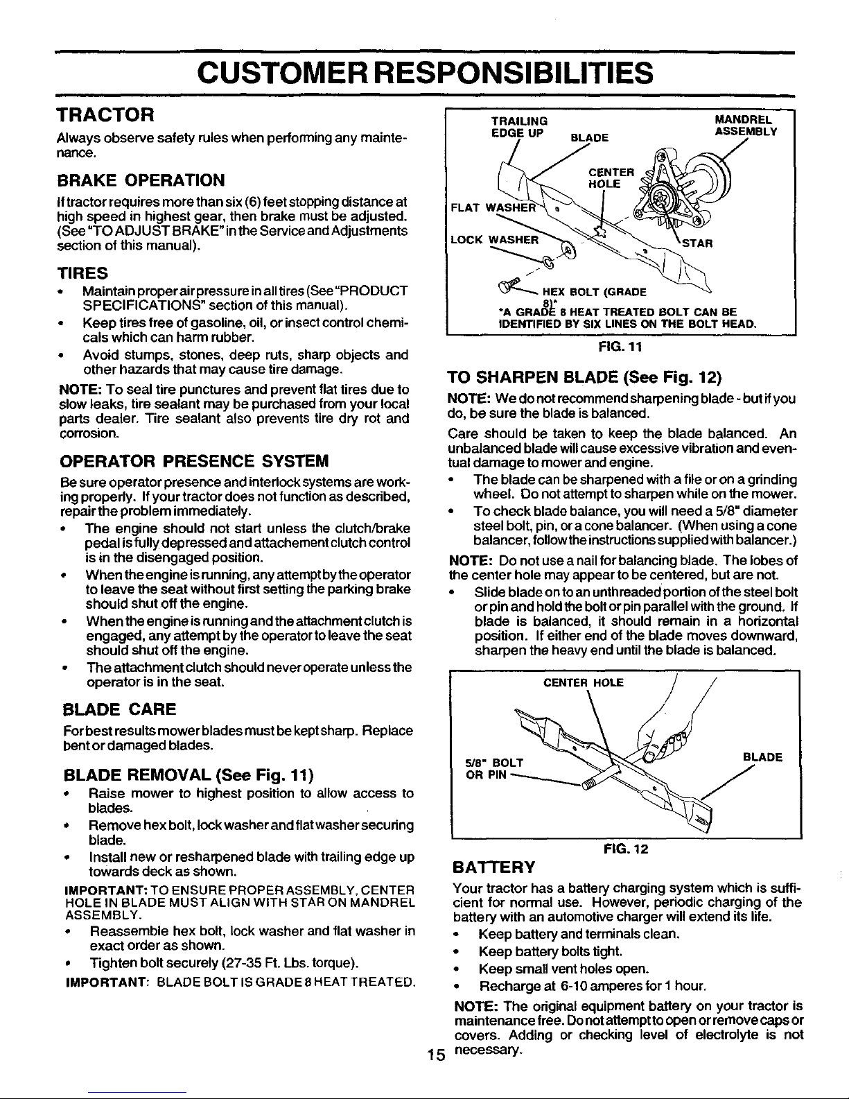
BLADE REMOVAL (See Fig. 11)
• Raise mower to highest position to allow access to
blades.
• Remove hex bolt, lockwasher and fiatwashersecuring
blade.
• Install new or resharpened blade with trailingedge up
towards deck as shown.
IMPORTANT: TO ENSURE PROPER ASSEMBLY. CENTER
HOLE IN BLADE MUST ALIGN WITH STAR ON MANDREL
ASSEMBLY.
• Reassemble hex bolt, lock washer and flat washer in
exact order as shown.
• Tighten bolt securely (27-35 Ft. Lbs. torque).
IMPORTANT: BLADE BOLT IS GRADE 8 HEAT TREATED.
TRAILING MANDREL
EDGE UP BLADE ASSEMBLY
FLAT
LOCK WASHER
(_"-- HEX BOLT (GRADE
8"1'
*A GRADE 8 HEAT TREATED BOLT CAN BE
IDENTIFIED BY SIX LINES ON THE BOLT HEAD.
FIG. 11
TO SHARPEN BLADE (See Fig. 12)
NOTE: We do not recommendsharpening blade - butifyou
do, be sure the blade is balanced,
Care should be taken to keep the blade balanced. An
unbalanced blade willcause excessive vibrationand even-
tual damage to mower and engine.
• The blade can be sharpened with a file oron agrinding
wheel. Do not attempt tosharpen while on the mower.
• To check blade balance, you will need a 5/8" diameter
steel bolt, pin, oracone balancer. (When using a cone
balancer, follow the instructionssuppliedwithbalancer.)
NOTE: Do not use a nailfor balancing blade. The lobes of
the center hole may appear to be centered, but are not.
• Slide blade onto anuntbreaded portion ofthe steel bolt
or pinand holdthe boltor pinparallel withthe ground. If
blade is balanced, it should remain in a horizontal
position. If either end of the blade moves downward,
sharpen the heavy end until the blade is balanced.
15
CENTER HOLE / /
us.SOL 'ADE
OR
FIG. 12
BATTERY
Your tractor has a battery charging system which is suffi-
cient for normal use. However, periodic charging of the
battery with an automotive charger will extend its life.
Keep battery and terminals clean.
• Keep battery boltstight.
• Keep small vent holes open.
• Recharge at 6-10 amperes for I hour.
NOTE: The original equipment battery on your tractor is
maintenance free. Donotattempttoopen or remove caps or
covers. Adding or checking level of electrolyte is not
necessary.
 Loading...