

Page 1

, Ht f
TM
Read this Owner's Manual and follow
all Warnings and Safety Instructions.
Failure to do so can result in serious
injury.
:TRI742S|1I
LAWN TRACTOR
ALWAYS WEAR EYE PROTECTION DURING OPERATION
it WAHNIN*;
169553 4.6.99 JH
Printed in U.S.A.
Page 2

SAFFTVHIM tS
A
M, i ' .
FAILURE TO OBSER^
Read, uiidefstand, and follow all instructs
. .. re- "M * t, r iu «a'f.i ^
Tri)* ilif.i/. ,sv ,or^!oi-* s'ljffb ,v~> are
¡е;г»»л liW I r.j.»3<a№ ìj h. i-
Ol ,Ь|е^ ^ J_,* f t, f ^ * si AC.,
whrh гоиЧ t*e prKa«i if and mrcwp о/ ihe oHdr
be tne area ь dea' of otnet people betoie ng.
Jtofi tiB'hin- i‘ ati'/one i-mein tt” r^ea
fie 'er rarrv ■a'ls^ngerDo n 5f тол III -everse unless absolutely neeessarv. Ai
wa a |{,cl down and beh rd before and wh'le backing,
p- 'W4re > f the tarwe* dccharqe di't* tiop am oo net point
i» di an/'jiife Do n< jt operate the mo wet withcut either the
entire gta® ' -atrhf r r.<- ihe auard
oD* d... 0 Ь;*СГ' * wTrg
f TvW lea 0 3 machins unattended Always turn
blades sei parking Drake, stop engine, and remove keys
disniotiiuirg
Turn off blades when not mowing.
Stop engine before removing grass catcher or undogging
chute.
Mow oniy in daylight or good artificial light.
Do not operate the machine while under the influence of
alcohol or drugs.
Watch for traffic when operating near or crossing roadways.
Use extra care when loading or unloading the machine into
a trailer or truck.
II. SLOPE OPERATION
Slopes are a major factor related to loss-of-control and
tipover accidents, which can result in severe injuiY or death.
All slopes require extra caution. If you cannot back up the
slope or if you feel uneasy on it, do not mow it.
DO:
Mow up and down slopes, not across.
Remove obstacles such as rocks, tree limbs, etc.
Watch for holes, ruts, or bumps. Uneven terrain could
overturn the machine. Tail grass can hide obstacles.
Use stow speed. Choose a low gear so that you will not have
to stop or shift while on the slope.
Follow the manufacturer’s recommendations for wheel
weights or counterweights to improve stability.
Use extra care with grass catchers or other attachments.
These can change the stability of the machine.
Keep all movement on the slopes slow and gradual. Do not
make sudden changes in speed or direction.
Avoid starting or stopping on a slope. If tires lose traction,
disengage the blades and proceed slowly straight down
the slope.
DO NOT:
• Do not turn on slopes unless necessary, and then, turn
slowly and gradually downhill, if possible.
• Do not mow near drop-offs, ditches, or embankments. The
mower could suddenly turn over if a wheel is over the edge
of a cliff or ditch, or if an edge caves in.
• Do not mow on wet grass. Reduced traction could cause
sliding.
• Do not try to stabilize the machine by putting your foot on
the ground.
• Do not use grass catcher on steep slopes.
'TING MACHINE li
i‘r F ,< r ■ ^ ii-
ip place
CAPABLE(
AFETY INI
IS in the manual
smiliar with the
IF AMPUTATIN
A
И If ( i. I
ih " ^tl '1'Г,
Tragic accidents can occur if the operator is not alert to the
; ' — 11» • < . j.M. 1 f r - I.>r-., .«I»- . 4'Hi j >1 { • • it'*-
.( > "r I 'Ч' ''mc.f i о u tt-t t
' He 3. -«I j.id tun, rath«'- oif if children enter the area
• Before and when backing, look behind and down for small
• Never carry children. They may fail off and be seriously
• Never aiiow children to operate the machine.
• Use extra cate wf;en approaching blind corners, shrubs,
I HANDS,
DULD RE!
Keep 'vicre’i jut ii*h'Mnov^rqai6c andi.iidb the v. | i.ij
-j - , i lOj A I p ¡,^'Llf _.iUt
chidieri
injurg'd or intedere v^ith safe machine operation.
trees, c* r=ther objects that ma/ obscure vision.
ND FEET AND THROWING <
ULT IN SERIOUS INJURY О
,i» t' .e 11H - W ri , iCt'vliy Ato. 1 r -iii 'c
i¥. SERVICE
• Use extra caro in handling gasoline and other fuels. They
are flammable and vapors are explosive.
- Use only an approved container,
• Never remove gas cap or add fuel with the engine running.
Allow engine to cooi before refueling. Do not smoke.
- Never refuel the machine indoors.
- Never store the machine or fuel container inside where
there IS an open fiame, such as a water heater.
• Never run a mactiirie inside a biosed area.
• Keep nuts and bolts, especially blade attachment bolts, tight
and keep equipment in good condition.
• Never tamper with safety devices. Check their proper
operation regularly.
• Keep machine free of grass, leaves, or other debris build-up.
Clean oil or fuel spillage. Allow machine to cool before
storing.
• Stop and inspect the equipment if you strike an object.
Repair, if necessary, before restarting.
• Never make adjustments or repairs with the engine running.
• Grass catcher components are subject to wear, damage,
and deterioration, which could expose moving parts or allow
objects to be thrown. Frequently check components and
replace with manufacturer's recommended parts, when
necessary.
® Mower blades are sharp and can cut. Wrap the blade(s) or
wear gloves, and use extra caution when servicing them.
» Check brake operation frequently. Adjust and service as
required.
Look for this symbol to point out
important safety precautions. It means
A
A
CAynON!!! BECOME ALERT!»! YOUR
SAFETY IS lN¥OL¥ED.
CAUTION: Always disconnect spark
plug wire and place wire where it
cannot contact spark plug in order to
prewent accidental starting when set
ting up, transporting, adjusting or mak
ing repairs.
A WARNING A
The engine exhaust from this product con
tains chemicals known to the State of Cali
fornia to cause cancer, birth defects, or
other reproductiwe harm.
Page 3

•J- .1*1- ^
'Jyr.ofii R
PPR1742STB
"jC r-.i/-L
MUMf.if:
.^rt i > I'Ht Hi- L
iHf ai'jI'LL 4Mi,
, ri l~r I IHi »t t nr . -I T r
OF PURCHASE AND KEEPINA SAFE PLACE FOR FUTURE |
-tr FI- rin>l£il _ _
''Rr« 1‘Fl h!-'M ..jsVbfcR. '
_MUMBERSWILL
:USTOMER RESPONSIBILiTIES
Read and observe the safety rules.
Follow a regular schedule in maintaining, caring for and
using your tractor.
Follow the instructions under "Customer Responsibilities"
and “Storage" sections of this manual.
'EARNING* Thic tractor i=- oqijipport with an internal com-
ijGtor anoint; and ahjuU net Ue jsf J on l, fit^r any
iiifTipiovu*] .'titeal ctirft-rea. brush uoieifd c»i gra^; cuy
■'6(i land unless the engine's exhaust syalem iS equipi.ed
ith a •'pa'k arrester roeetim applrable local or state !rws
any} If d impark dfir jict i'. Used, ¡t i'Odid be niaintained
effective w jrking ordet b\ the opeiator.
1 the state of California the abo ve ic- required by law (Section
442 of the California Public Resources Code). Otherstates
lay have similar laws. Fede ral laws apply on federal lands.
,4^ ' , ti I'H . I jM
__
■
SkLVE CLEARANC
GROUND
TIRE PRESSURE:
CHARGING SYSTEM:
ERY:
BLADE BOLT TORQUE:
1.2
1.5
2.4
3.5
4,8
f T|| 5.4
REVERSE: 1.5
hifcrn J r S'
Ml4H _ lOj Gi
! AMt H/' I I. H ,
AMF/MH
P/iN CFA iUO
_ i ASt^ :j7) U ■ H
.•;-3f,Fr LEi
Page 4

FABi F or eONTFNTS
SAFETY RULES ..................................................... 2
PRODUCT SPECIFICATIONS ................................. 3
CUSTOMER RESPONSIBILITIES ................... 3,14-17
WARRANTY ......................
ASSEMBLY
..............................................................
.............................................
..6-8
OPERATION ................................................................ii-13
4
REPAIR PARI T tro
PARTS ORDERING.................................. BACKPAGE
MAIMTENANCESCHEDULE ................................... 14
SERWICEA»ADJUSTMENTS ....................... 1S-24
STORAGE .........................................................25
.................................... 26-27
.......................................
3(M5
LIMITED WARRANTY
The Manufacturer warrants to the originai consumer purchaser that this product as manufactured P free from defecss in
materials end wo'krTianship. For a period of iwo (2} years from date of purchase by ttie original consumer purchaser we vril!
repair or replace, at our option, without charge for parts or labor incurred in replacing parts, any part which we find to be
defective due to materials or workmarship This Warranty T subject ¡o the following lirr.ilations and e^lusions
1. This wairariiy dues not appiy to the fiigtne. other than FHP (FouiaaTYeeci Eater) .Tianuiaciured trarisaxie/transiTHCSior.
compcneiiis. battery (except as noted below) or corripunentc Darts thereo. Please refur to the appdcabie
manufacturers warranty on these items.
2. Transportation charges for the movement of any power equipment unit or attachment are the responsibility me
purchaser. Transportation charges for any parts submitted for replacement under this warranty must be paid by the
purchaser unless such return is requested by Frigidaire Home Products (Poufan/Weed Eater).
3. Battery Warranty: On products equipped with a Battery, we will .replace, without charge to you, any battery which we find
to be defective in manufacture, during the first ninety (90) days of ownership. After ninety (90) days, we will exchange
the Battery, charging you 1/12 of the price of a new Battery for each full month from the date of the original sale. Battery
must be maintained in accordance with the instructions furnished.
4. The Warranty period for any products used for rental or commercial purposes is limited to 90 days from the date of
original purchase.
5. This Warranty applies only to products which have been properly assembled, adjusted, operated, and maintained in
accordance with the instructions furnished. This Warranty does not apply to any product which has been subjected to
alteration, misuse, abuse, improper assembly or installation, delivery damage, or to normal wear of the product.
6. Exclusions: Excluded from this Warranty are belts, blades, blade adapters, normal wear, normal adjustments, standard
hardware and normal maintenance.
7. In the event you have a claim under this Warranty, you must return the product to an authorized service dealer.
Should you have any unanswered questions concerning this Warranty, please contact:
Frigidaire Home Products
Outdoor Products Customer Service Dept.
250 Bobby Jones Expressway
Augusta, GA 30909 USA
giving the model number, serial number and date of purchase of your product and the name and address of the authorized
dealer from whom it was purchased.
THIS WARRANTY DOES NOT APPLY TO INCIDENTAL OR CONSEQUENTIAL DAMAGES AND ANY IMPLIED WARRAN
TIES ARE LIMITED TO THE SAME TIME PERIODS STATED HEREIN FOR OUR EXPRESSED WARRANTIES. Some areas
do not allow the limitation of consequential damages or limitations of how long an implied Warranty may last, so the above
limitations or exclusions may not apply to you. This Warranty gives you specific legal rights, and you may have other rights
which vary from locale to locale.
This is a limited Warranty within the meaning of that term as defined in the Magnuson-Moss Act of 1975.
In Canada contact:
Frigidaire Home Products
7075 Ordan Drive
Mississauga, Ontario
L5T 1K6
Page 5
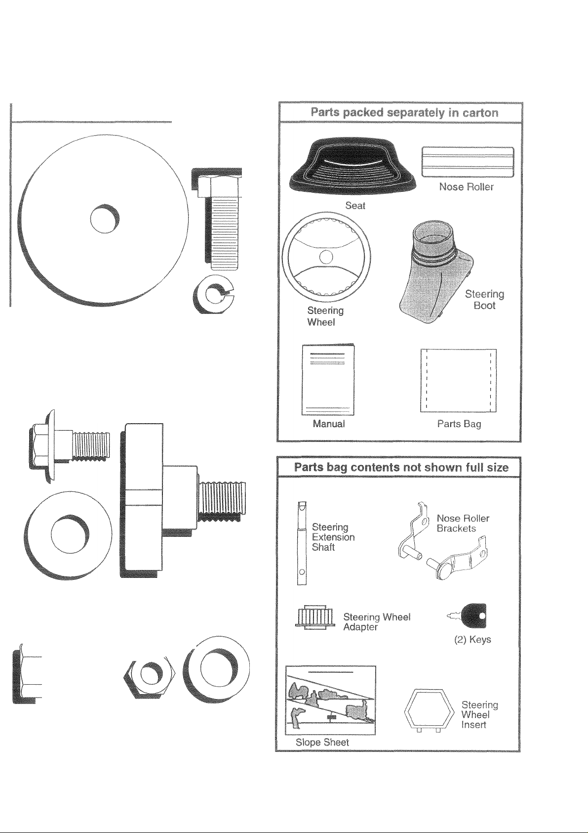
CONTEMTS OF HARDWARE PACK
Parts Bag contents showri full size
(1) Large Flat Washer Lockwasher 3/8
5X Bolt
3/8-16 X 1
§
o
(1) Hex Bolt 5/16-18 X 1-1/4 (1) Locknut 5/16-18
(1) Shoulder Bolt 5/16-18
(1)Knob
(1) Washer 17/32 x 1 -3/16 x 12 Gauge
(2) Washers 17/32 x7/8x 16 Ga.
(2) Hex Bolts 3/8-16 x 1 (2) Nylon Locknuts 3/8-16
Page 6
Yoi
safi
tool
in’ 3 ,,fti sembtedatthefactorvwithexceDtionofthosepartsleftunassembiedforshippinf purposes, Toensure
. i> , 1 -1 .. onofyoii fi'.»■[ . ;■ M-ardware you assemble must befightened securely. Use the correct
t r ,-^r, .sureprci i? ...
TOC
A sc
wrefii. i»
(1) &'to'«re;«rri
(2) 1/2" wrench
When right and left hand is mentioned in this manual, it
means when you are in the operating position (seated
behind the steering wheel).
makeas'Vr-' ‘ tor is id
sted.
t-tiinv r n te
! ;re pre>i.uie gauge
TO REMO¥E TRACTOR FROIJ CAR
TON
UNPACK CARTON
• Remove all accessible loose parts and parts cartons from
carton (See page 5).
• Cut along lines on carton, from top to bottom, all fourcorners
of carton and lay panels flat.
• Check for any additional loose parts or cartons and remove.
BEFORE ROLLING TRACTOR OFF
SKID
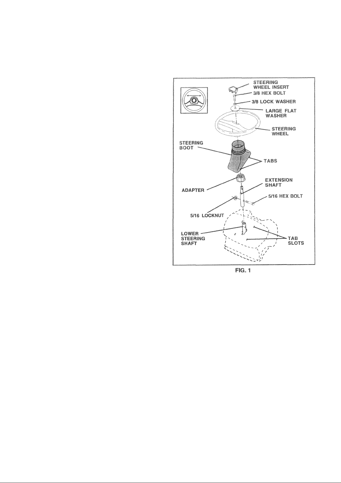
ATTACH STEERING WHEEL (See Fig. 1)
ASSEMBLE EXTENSION SHAFT AND BOOT
• Slide extension shaft onto lower steering shaft. Align
mounting holes in extension and lower shafts and install 5/
16 hex bolt and locknut. Tighten securely.
IMPORTANT: TIGHTEN BOLT AND NUT SECURELY TO
18-22 FT. LBS TORQUE.
• Place tabs of steering boot over tab slots in dash and push
down to secure.
INSTALL STEERING WHEEL
• Position front wheels of the tractor so they are pointing
straight forward.
• Slide steering wheel adapter onto steering shaft extension.
• Position steering wheel so cross bars are horizontal (left to
right) and slide inside boot and onto adapter.
• Assemble large flat washer, 3/8 lock washer, 3/8 hex bolt
and tighten securely.
• Snap steering wheel insert into center of steering wheel.
• Remove protective materials from tractor hood and grill.
IMPORTANT; CHECK FOR AND REMOVE ANY STAPLES
IN SKID THAT MAY PUNCTURE TIRES WHERE
TRACTOR IS TO ROLL OFF SKID.
TO ROLL TRACTOR OFF SK!D (See Opera
tion section for location and fynction of con
trols)
• Press lift lever plunger and raise attachment lift lever to its
highest position.
• Release parking brake by depressing clutch/brake pedal.
® Place gearshift lever in neutral (N) position.
• Roll tractor forward off skid.
• Remove banding holding discharge guard up against
tractor.
Page 7
ASSEMBLY
:::HECiC tY (See Fig. 2)
Lift seat pan to raised position and open batteiy box door.
If this battery is put into service after month and year
indicated on label (label located between terminals) charge
battery for minlfnum of one hour at 6-10 amps. (See "BAT
TERY^ in CUSTOMER RESPONSIBILITIES section of this
manual for charging instructions).
SEAT PAI
LABEL
BATTERY BOX
DOOR
TERMINAL-
FIG. 2
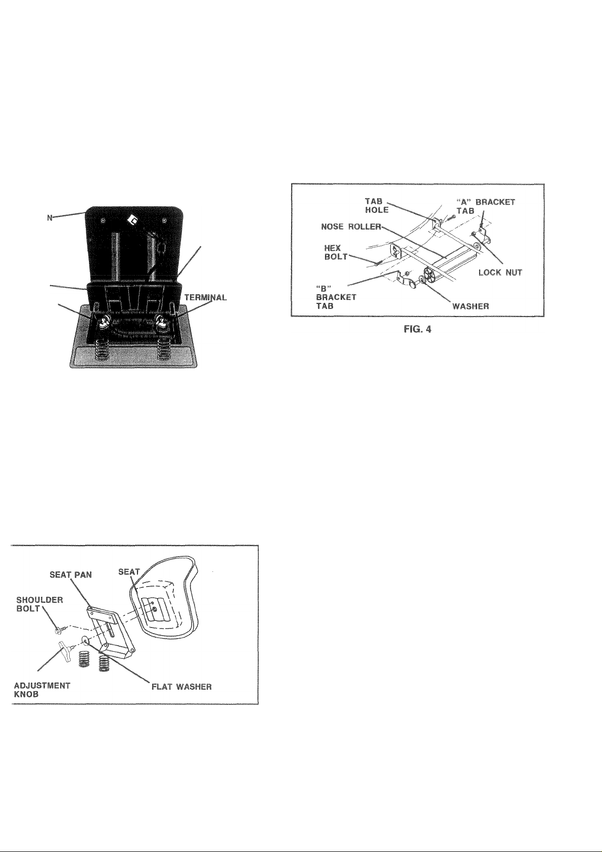
^STALL SEAT (See Fig. 3)
idjust seat before tightening adjustment knob.
Remove cardboard packing on seat pan.
Place seat on seat pan and assemble shoulder bolt. Tighten
shoulder bolt securely.
Assemble adjustment knob and flat washer loosely. Do not
tighten.
Lower seat into operating position and sit on seat.
Slide seat until a comfortable position is reached which
allows you to press clutch/brake pedal all the way down.
Get off seat without moving its adjusted position.
Raise seat and tighten adjustment knob securely.
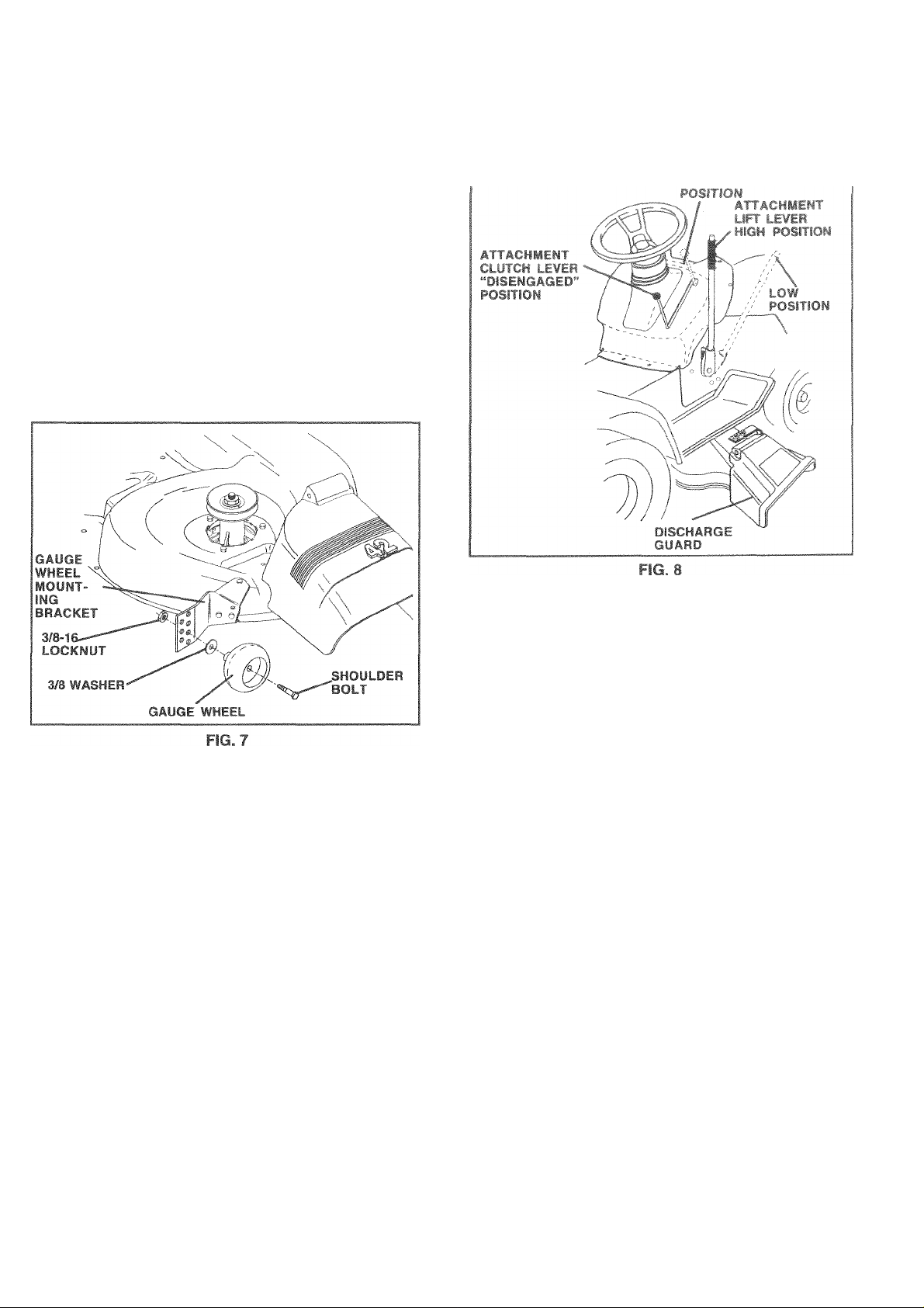
SE ROLLER (See Fig. 4)
• Position brackets, 17/32 x 7/8 x 16 gauge washers, and
nose roller between deck mounting brackets as shown. Be
sure to position brackets on correct side, as shown.
• Install 3/8-16 X 1 hex botts and 3/8-16 lock nu iwn.
Tighten hardware securely.
NOTE; Be sure bracket tabs are positioned in tab holes in
deck brackets.
CHECK TIRE PRESSURE
The tires on your tractor were overinfiated at the factory for
shipping purposes. Correct tire pressure is important for
best cutting performance.
• Reduce tire pressure to PSI shown in “PRODUCT SPECI
FICATIONS^ section of this manual.
CHECK DECK LEYELNESS
For best cutting results, mower housing should be properly
feveied. See ‘TO LEVEL MOWER HOUSING” in the
Service and Adjustments section of this manual.
CHECK FOR PROPER POSITION OF ALL BELTS
See the figures that are shown for replacing motion and
mower blade drive belts in the Service and Adjustments
section of this manual. Verify that the belts are routed
correctly.
CHECK BRAKE SYSTEM
After you ¡earn how to operate your tractor, check to see
that the brake is properly adjusted. See ‘TO ADJUST
BRAKE” in the Service and Adjustments section of this
manuai.
FIG. 3
Page 8

'CHECKLIST
BE
DU OPERATE
AND ENJO"]
TRACTOR, WE WISH TO ASSURE THA T
RL. At. I “ ^ f ^ Vir- I |i ji I ^ ^ ^
\ tj‘t > »f i i
lU RECEIVE
' If )f! f- Ri Vi •
. " 5-JV“ ' COTLE
t LtA^i PtitEf^ to' Zll i Pf fz. Z‘‘LI :> i
, Ai< >S'“'rthi/ ¡n-ir»*! tmtii h st'f bi-i=<i i. 'rif.l< tito
f < remdinino loose 034=^ ii oer.-’f.
Piftb^V if praoerlv piep-irw. «ird claiotr» {Minimum 1
•".Ou. it o -i< ips|
Pe 4 i adjusted i orn%rtably and tightcne'i sejrev-
pii j.r: *tt propedy hfiatfcd |Fc' shippioj^ puv ('j-rs, the
tires *ere oierinflated at >4*= fartory*
Be sura mower cieclr is properly iewfed '^sde to side/front-
io rear tor oesl rutting resuii*^ jl ires roust ue properly
iniiat&d ‘‘jS ievenf'q)
Check mower and drive belts Be sure they are routed
/
properly around pulleys and inside all belt keepers
/
Check wiring. See that al! connections are slil! secure and
wires are properly clamped.
WHILE LEARNING HOW TO USE YOUR TRACTOR, PA Y
EXTRA ATTENTION TO THE FOLLOWING IMPORTANT
ITEMS:
/ Engine oil is at proper ievel.
✓ Fuel tank is filled with fresh, clean, regular unleaded
gasoline.
/ Become familiar with all controls - their location and func
tion. Operate them before you start the engine.
/ Be sure brake system is in safe operating condition.
8
Page 9

OPERATION
These symbols may appear on your tractor or in literature supplied with the product. Learn and understand their meaning.
Í Í
En r.
BATTERY
ENGINE ON ENGINE OFF OIL PRESSURE LIGHTS ON
CAUTION OR REVERSE
WARNING
STOP
\ X
i l\l Sk
FUEL
CHOKE MOWER HEIGHT PARKING BRAKE UNLOCKED MOWER LIFT
FORWARD
a= 0Í
OVER TEMP
LOCKED
FAST
LIGHT
d“
A
SLOW
lu
I
i* R N H L (®)|I
ATTACHMENT REVERSE NEUTRAL
TUTCH ENGAGED
«
ATTACHMENT
IGNITION
DANGER, KEEP HANDS AND FEET AWAY
CLUTCH DISENGAGED
«
KEEP AREA CLEAR SLOPE HAZARDS
HIGH LOW
(SEE SAFETY RULES SECTION)
<pH“
PARKING BRAKE
=/<#*•
FREE WHEEL
(Automatic Models only)
4 = fei
Page 10
OPERATION
KNOW YOUR TRACTOR
F' > I ‘ '*S OWNER' ^ T • UAL AND SÄFEW RULES BEFORE OPERATING YOU'* F-": T1
Compare ihe illusirat«ons with your tfaclor to familiarize yourself with the total ions of various controls and adjustrrier'iis, Sav e
this manual for future reference.
Our tractors conform to the safety standards of the American National Standards institute.
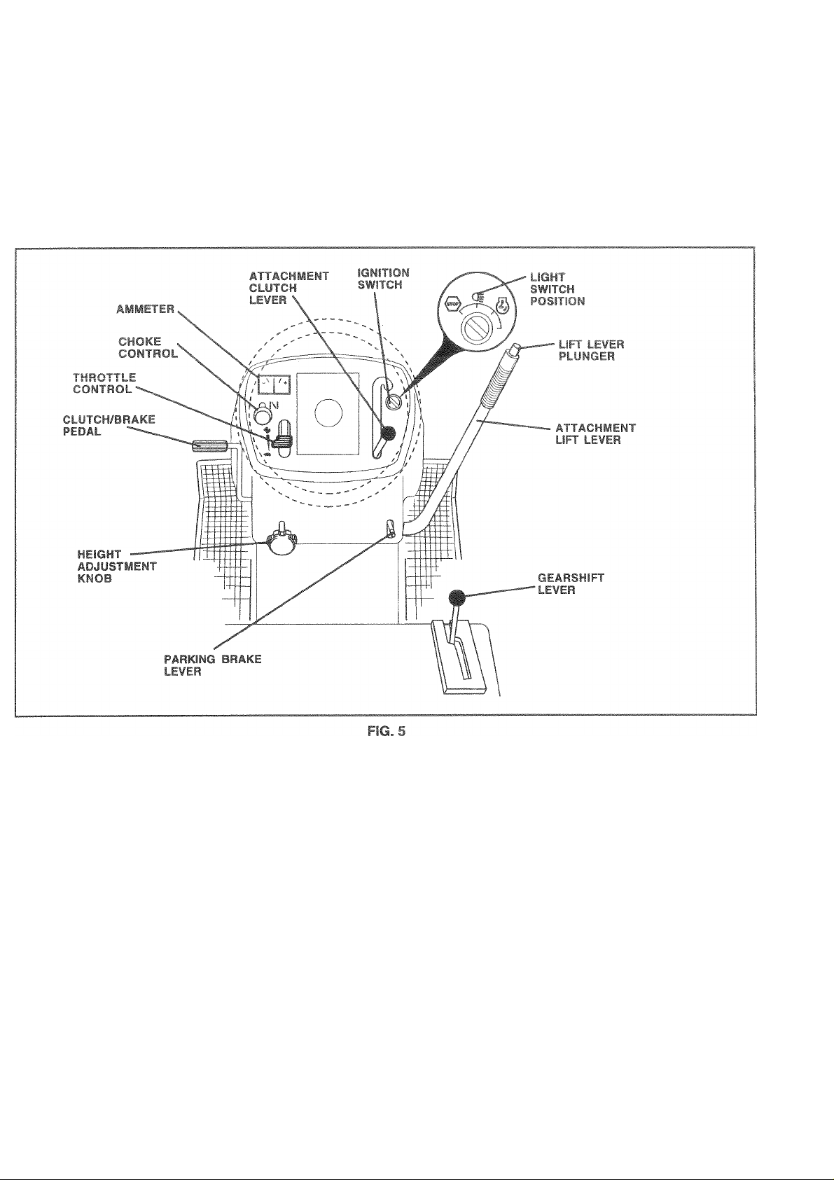
ATTACHMENT CLUTCH LEVER: Used to engage the
mower blades, ot ether attachments mounted to your
tractor.
LIGHT SWITCH POSITION - Turns the headlights on and
off.
THROTTLE CONTROL: Used to control engine speed.
CLUTCH/BRAKE PEDAL; Used for declutching and brak
ing the tractor and starting the engine.
CHOKE CONTROL - Used when starting a cold engine.
HEIGHT ADJUSTMENT KNOB - Used to adjustthe mower
cutting height.
GEARSHIFT LEVER: Selects the speed and direction of
tractor.
AMMETER - Indicates charging (+) or discharging (-) of
battery.
PARKING BRAKE LEVER: Locks ciutch/brake pedal into
the brake position.
ATTACHMENT LIFT LEVER: Used to raise, lower, and
adjust the mower deck or other attachments mounted to
your tractor.
LIFT LEVER PLUNGER: Used to release attachment lift
lever when changing its position.
IGNITION SWITCH: Used for starting and stopping the
engine.
10
Page 11
OPERATION
The operation of any tractor can result in foreign objects thrown Into the eyes, which can
f'i, I . i' ■ - ‘ wfs wear safety gla* n »Ids wliite operating four
.Ijusimentso '^^recoitiifiendawidevisionsafetfmask
¡safety glasses.
iO% h»
f!'.F*^ iL-.i fltf. h;
ISillQ
witch. When engine is running, any attempt by the
I..I >r .. ■ • f •'»pihi.ui fsrtf ‘ eii! ig hi p, rking
rake will shut off the engine.
tir.lii
Place parking brake lever in “ENGAGED” nosition and
n »i Kill. lutir'Di^rc pV" rtl Peci d shouicl
rctiiii.in ni \K j ill n i\t tr^ pelkny i rake wili
held iracl«. ii<e
CHOKE
CONTROL
HROTTLE
ONTROL
^BRAKE”
POSITION Г- \\ /
'XUTCH/BRÄKE
“DRIVE” HEIGHT
rOSITiON ADIUSÌMENT
111 ii/r<i .r.. isr Ini iiii» I iii f,«/> I-‘ poaiiori and
ATTACHMENT CtyiCH LEVER
'‘EMGAGED“ POSITION
IGNITION KEY
/ .“DISENGAGED”
POSITION
.PARKING
n W BRAKE LEVER
“ENGAGED”
POSITION
GEARSHIFT
LEVER
PARKING BRAKE
rpop
“DISENGAGED”
posmoN
FIG. 6
TOPPING (See Fig. 6)
OWEFf B!J\DES"
To stop mower blades,move attachment clutch lever to
‘'DISENGAGED” position.
ROUND DRIVE-
To Gtop^groand drive, depress clutch/brake pedal into full
“BBAKt’' position,
idove gearshift lever to neutral (N) position.
■dGSNE
Move throttle control to slow position.
JIL Failure to move th rottle control to slow position and
lowing engineto idle before stopping maycause engine to
ackfire”.
Turn ignition key to “OFF” position and remove key. Always
remove key when leaving tractor to prevent unauthorized
use.
Never use choke to stop engine.
IMPORTANT;: LEAVING
POSITION C »THER Tl-IAN "OFF" И /ILL C, 4USE THE
ÎTHEIGNITIC iN SWI"ГСН IN ANY
BATTERY TC1 BE DISCIHARGED, (DEAD).
NOTE: Unde r certain c(jnditlons wher
idle with the er
f .1! r >t gl
igine runni ng, hot engine
iss. To eiimin
1 tractoi
exhaus
ate this
Iways эр engir lina tractor on qra
G*»ttl!öil %1‘Wfa/'. sten W »r if« “Olrs
Ä
pleteif, as described above, before leav
ing llie operator's positiciir to empty
grass catcher, eie.
TO ySF HBOl 11 F G ONTROL (See Fig. 6)
Always operate engifie ai full throttle.
® Operating engine at less 'dan full throttle reduces the
battery changing rate
® Full throttle offers the best bagcjirirj and mower perform
ance
TO USE CHOKE CONTROL (See Fig. 6)
Use choke control whenever you are starting a cold engine.
Do not use to start a warm engine,
* To engage choke control, pull knob out. Slowly push knob
in to disengage
TO MO¥E FORWARD AND BACKWARD (See Fig. 6|
The direction and speed of movement is controlled by the
gearshift lever.
« Start Sfj t<«r 1 .V- -Jl fir- -.I--* re 1 ‘ Vj i G r '■ V
_h<ft tf vui n (V. utivi ii >) püjiiwri
8 ktnv«- vj-L '-nifi le.—■ i> 'Ifc'.iifc«’ r lil^fi
8 -k My 'f iSP )n* r, ff,.
IWrUPiANT r ■’Itir ’RZ ir.r A I (iMt-l L rr f( p
Litl'Jits dicnii irf.-iiniMiti jj'-l', rCitfiE
H'-LiDV ,V!LL GUUi'it-J i fit II D F* I • f'
G-l r
TO ADJUST MOV^tK CyrriilG HFiGhl (See F:g. e|
The cuh'iip Iwiuh! G llnd l.y * . ul- u the height
adjusirr.er<tl«r '!• r <T.‘I'Cff dirr'iD..;
* Turn Ktk D ' ioi L\v sr i ^! >11 <r( iitf r I h: ight.
® Turn I'iid. GviU.ik rcl'ji./ribi-(k Rt-^low i cutiing height.
The cutting iieight range Lsapproximattiyi to 4“. The
heights are nw asured from the ground to the biade tip with
the engine not running These heights are approximate and
may vary dependii ig tpor, so! conditions, height grass
and types of grass being mowed.
* The average lawn should be cut to approximately 2-1 /2
inches during the cool season and to over 3 inches
during hot months. For healthier and better looking
lawns, mow often and after moderate growth.
* For best cutting performance, grass over 6 inches in
height should be mowed twice. Make the first cut
11
relatively high; the second to desired height.
■ is standing
t y3S0S шзу
l'«)- |. .H,i
ireas
Page 12
■OPFRATSON
TO,
Gauge wheels are properly adjusted when they are slightly
off the ground when mower is at the desired cutting height in
' I -f-lir fs r,'.- id 'Svf (h. ,
t>i !’•» I'd (. i ( r f Ijt- -.rr • -i| •!,, , |.,** i '• i!l
conditions.
' Adjust lo dfesued c.J«i->g r(e«giii (Ste ‘T'J AfuLihi
• With mower in desired height of cut position, gauge wheels
• Repeat for opposite side installing gauge wheel in same
JUS
T GAUGE WHEEI
wh€
Adjusi gaug'-. uhte's Witt> n a il« le%el .^usface
MOWER ('U FTiNG HEKyHT -n ft*#* i5p«ra‘ior> s«=—tjon of >hi..
manual}.
should be assembled so they are slightly off the ground.
Install gauge wheel in appropriate hole with shoulder bolt, 3/
8 washer, and 3/8-16 locknut and tighten securely.
adjustment hole.
iFîa
TO OPERATE ON HILLS
TO OPERATE MOWER (See Fig. 8)
Your tractor is equipped with an operator presence sensing
switch. Any attempt by the operatorio leave the seat with
the engine running and the attachment clutch engaged will
shut off the engine.
« Select desired height of cut.
* Lower mower with attachmenr lift control.
* Start mower blades by engaging attachment clutch control.
® TO STOP MOWER BLADES - disengage attachment clutch
control.
CAUTION: Do not operate the mower
without either the entire grass catcher,
on mowers so equipped, or the dis
A
charge guard in place.
CAUTION: Do not drive up or down
hills with slopes greater than 15° and
A
• Choose the slowest speed before starting up or down hills.
• Avoid stopping or changing speed on hills.
• If slowing is necessary, move throttle control lever to slower
position.
• It stopping is absolutely necessary, push clutch/brake
pedal quickly to brake position and engage parking brake.
• Move gearshift lever to 1st gear and be sure you have
allowed room for tractor to roll slightly as you restart move
ment.
® To restart movement, slowly release parking brake and
clutch/brake pedal.
® Make all turns slowly.
do not drive across any slope. See the
slope guide in the back of this manual.
TO TRANSPORT
• Raise attachment lift to highest position with attachment lift
control.
• When pushing or towing your tractor, be sure gearshift lever
is in neutral (N) position.
» Do not push or tow tractor at more than five (5) MPH.
NOTE: To protect hood from damage when transporting
your tractor on a truck ora trailer, be sure hood is closed and
secured to tractor. Use an appropriate means of tying hood
to tractor (rope, cord, etc.).
TOWING CARTS AND OTHER ATTACHMENTS
Tow only the adachrr.ents that are fecomrnended by ard
comply with soecifications of the manutocturer cf your
tractof. Use common sense when sowing Too heamr ct a
load, while on a slope, is dangerous. Tires car lose Ira-ction
with the ground and cause you to lose control of yourtractor.
12
Page 13

OPEFi;^
kTlOW
w
B H 8
«
iSEFORE STJ^iRTING THE EN
JHECIC ENGINE 0
The engine In y
factory, aliBady f
Check ecgiiie oil
||L LEYEL fSee Fig. 141
our tractor 'has been ship
lied iwith summer weight oi
with tractor on level groun
GINE
*pecl, 1шш the
1!
Remove oil fill c;ap/dipstick and wipe cieai 1, reinsert the
0
dipstick and sersi
T 5“ 1“ S 1 gij |.> 1
J f fn |< 9 i h
cap tight, wait for a few se<
. If nscossairy, add oil uniii '!
^ ^ HD
2onds, remove
™LILL”markon
or cold weather operation you should change oil for easier
.< li .1 jtf U'l i/iji'i II - CHr-‘rti tn ill tkisuiiBt
f I 1 'tr nr.i, i
I') I"! r.j M'4i! 11 a, r,H rfii S' HP-:|: .r>Fi')!<it‘er
l-''!« 1. il > till" (fi-S'lOf •
riii <1)^1 tjif •!'- Irt-'f< f I' «, r ci'jfr' иц|г > I ''‘.«le
v< t>i ! (fiinwiom ol P < ‘ iB.if iiLf'll 1=* ide<J yarol'iit ,vii
•I s И-14 .¡i f >i aO e-..)i Jt|'0 II i.i-iPf'UiP /Ji ь
>iIm jit i".i («Ч' Ш -'itii ' « irN ,'p iup' iti
qi.ar.tiii that i -ii h*- wifhir 'A | j S'-ч'ь *ur!
freshness.
iPoeiAilT, WHLri urEFiATirt^ IIJ ТЕМРГ r.ATURE.
Flow da'1 |ti C| FFiESl! • ,l LAi J V^lH I LP i.HAt«-
дсоппг lO MELl in ;URF (lOOn ( 01 h WFolHtH
! ARFirJO
*<IPi%iNG Ьлреич!. t’iri'iK aV- ihrt. ■'ь|„,! Ы» nd^^P
>ris ille'l i.ja^ohi f ujI ly c-lhalioi i nitihaii!ii) i, ди
-tratf moi !мгелК.(.Ь!еа^_.1с.ььркгайо!'jnfJMrmdtiofKif
itfc duiinrj sp'faq- Acidii, ga- can rfamagt th- fuel
Ociii of (П engirit! Ahiif in stoiage Тэ a¥uid eiiyii-i
иЫеть, the fuel ovsfeni dnou.a be emptied befoie stoi-
jec.f 30 days or longer Drain the gas tank эШ the engine
nd ifcf it run until the luei line>- and carburetor зге empt;.
it tiesh fue. next s<=»asofi See Sioraye instructions fur
iditional inloimatiori fJevei ust engine s>( carbureft-r
' ararproducts in thefue i tankoi pr'iiTiarieiiidarrt ige may
ilCLir.
CA'JTiON. F'di ÍC festtom u* gas tairl*
“I
filler rieck. Do not overfill. Wipe off any
A
spilled oil or iuei Do not store, soiii or
ear neat jr¡ oper fíame.
3 .Ti.ai ENGINE i t 'u -
/hen starting the engine for the first time or if the engine
as run out of fuel, it will take extra cranking time to move
e ifjii in<’ t.ini* lu hr Ku’oe-
Sit on seat in operating position, depress clutch/brake
»tirfl siw ' |: ir-iiy hif ffEf't-.. f ,, hift ftiPi II i ^ 1*1. i dJ| fosition
f i> , nil-(.r mr‘( «’< *1 Imi II t'“trAi-ED” p •* II on
Move throttle control to fast position
• iUI-w ionin!c‘i! r Cl vrit cwn an<'ri''- in a
¥ li'f tifiine stad tiilc .iipt tri ch <ke rcr.irol rrsi ti~t be
needed.
ilD Bi t t -lErhiiq rPdQ ihp # ii n r lu cold Ntanii'g
OCfctiUl ccE IjcjIUW.
|i f il i f If ifiia loiiitii r n‘'inr' rc/il iivK fi if I”
lu 111 < <‘ii 1 rey ' O.J I T' 1-1 ( I k -I 'I j 111 t
■ in t nei r^iitin in'Ey - t. f in , tibwi... id p r
nil.til. 'f!l. ^mi.r iff !. > I it r IE /ill if ,
push choke control in, wait a few minutes and try again. If
f life til* nut lai , I ill .hr whift iciita! < nd
rcirv.
WARM WE
engine I
roughly,
and tiiei
• The alia
eiiQine 1
allow it
ATHER STAF
ngirie starts, sk
jegins to run s
pull the choice <
1 continue to p
chments and g
loes not accef
to warm up fc
ITING (50* F and above)
ywly push choke control in
moothly. if the enoine stan
iorifrol out sllgiitfy for a few:
ush the control in slowly.
round drive can now be use
>t the load, restart the eiic
V one rriiriute osino the о
until the
[s to run
seconds
id. If the
iirie and
hnkfk
pc
describeid above.
COLD WE#iTHER STAR'
id «ht 1 1 n i ^oi
• When engine starts, slowly push choke control in until the
ik-g.li ,i(*tr|'i < ‘•«UMJJiC pit! tb i ii'b
fill 4 I -iMjfl E I. 1^ „ .Jlsisnsli j if 11, 41^ I 6 I rl\ 1 1 ¡ if ni I
it jriJi ill
i.. «Ííbi nyjt _ » u1 I., f,i ( Ciljnl^ рч'ЧЬ I ij'4 'nkifÁ
Ы liqlul/b/f 'д If /'„f . > |k‘ .tr<> hr П • <> I It U '.i.ntllsr-
11 1
, I ) ,J ntlO'if ilOlr is Jl/
fniini IciMiv |hs III' ! q,,-, ' CMlir>r ¥ Ц11 nr
I иЬ fi.'N < n.p l, Í . I . , ill.i.t.u it,/“! t
ImU uh ¡.life; icmpdaiUffc.
Л1о SH ( -a«' I UMi *1 p Í .iríí^jn tf« rni lip
uifli .1 lU-ifr/f 'i и IIoj Oüi
shahilv.
fJOTE: Il it - hif]ii "jit'lüdc Ht« vs, lOoy ifEEfl) 'п in cold
Í'ifipfaturc ibr-l'jw VFtideслгЬи«til»'flic!mutur -rnay
Г|.1е1ЙчЬаас||иЛсик|ГЬс teriíiin^prnoitiijn ' Sit ‘TO
ADJUST GaRB'JRF roR ’litii-St*r 1(1 itnenis
Cfc-ction ul ifii- irijiiua!
MúwmG 4PS
’ M(>m jh 1 ilcJ b'* ptoncilyto! *.i't t.o.virig perfur-
пчпсе See'roi EVtl MCjWEFiHOn^.lN'S' •iith/ ''¡ervice
^rd Adjusti.'’Mfr rcJ: n cf n.-n ч!
' rii .rii • aii'j ..iJi i > hiu¥ к ah.Hjiu he dreri 1()Г iiimming.
Dr vest fhatf lipp'ngt'are disthaiged onto thr-jrea that has
beer cut Have the rut aiea to the right of the tractor. This
wii| msult 1(1 a more ri‘ n lBiiihutior, rf ,-i pp.'nqc and mote
uniform cutting.
= Vt/heE( mowing large- tas, -fartDytiriiingtotheryjlitf’nth.^t
c ippig-r и .i| difirharye •‘wa^ fmiri fEhtiib^ ffnA'' Uri' wayw гуцр (I round' I •'</, ir* i! f> jopii'K)
dtiectior ,>i?l<ina ‘etf »i.cid I >rr< t rit.i ¡k' •=Ьек , >■' f >g
' it ’0'^ . - (.smel, ».JÍ! . .. -'*1 'i. *. If di¡<
load c-id [ojicible fir^ f<nzv',fd iT'>n Jiir j '.1>рр1Пч' flefri
fuel i.ut ►-Ntwelv high 1гв ж-f -.'.и tu ! e t. >tqh
' [*onottiiow0ГЛ -u'hfciiiti m' V\nit,f4, wiii./liir,пин<ч
fr. lit . ncif: irahíu f hnip.' ik'- r c i” i 7 t.
il 10 Wirtes.
• Aif ly '» »r f' a' full к I'!'. o¡ f r П iv'n I '(
h^ ut f-tkr-i! Л П {i‘ii Hi I' jt I pro| I rti Ci|i|f
l- ‘f, it 1' I Ч •! t 1 ,.,ii J -;j. ' -y I < I, , , I. .
f I. ugf. 3' si t. J - ill... 11 Ow- I e lU . t p I 1. I a \ ; ¥. '1
is- (! - f|i| litj ■! ' «<í i! ‘Pf il
® '.УЬ'‘|| i. nl‘M's ■ inimi" I ‘ .| ij, i Í. rf ,,1-i
vill U(! ihe kii-iii ii.d qiii 'f p-u.,p.i., , )f tn.-
rrtäf hrr'r~ni ti.-ir,.t I) ^
13
Page 14
H wr^tpfiNSiBU
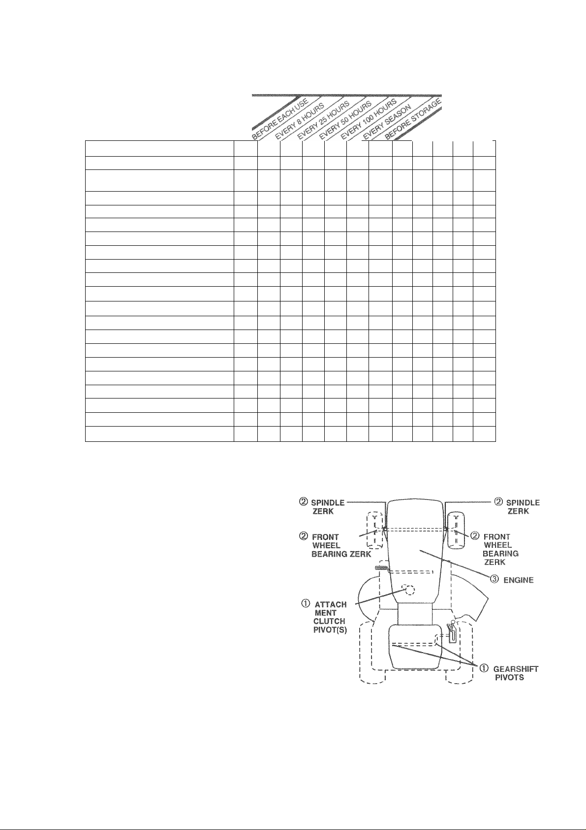
MAINTENANCE SCHEDULE
FILL IN DATES
AS YOU COMPLETE
REGULAR SERVICE
Check Brake Operation
Check Tire Pressure
ChecK Operator apn
l.icict-l
Lh^c(< for 1 or«;'» -
Mi=t M- i-Repla e BidJc
LKt'icatr.r Chart
C* fA Battery Lc^< 1
Cied'i Bate j md Te-r.
C“«? r » rsrSarlo ^
Adjust Blade B&itlsi rei<s«>
AujüS» Molrjii L>ri»e belt(Sl r^'i luii
Check Engine Oil Level
Change Engine Oil
Clean Air Filter
Clean Air Screen
Inspect Muffler/Spark Arrester
Replace Oil Filter (If equipped)
Clean Engine Cooling Fins
Replace Spark Plug
Replace Air Filter Paper Cartridge
Replace Fuel Filter
1 - Change more often when operating under a heavy load or in high ambient temperatures. 5 - if equipped with adjustable system.
2 - Service more often when operating in dirty or dusty conditions.
3 - If equipped with oil filter, change oil every 50 hours.
4 - Replace blades more often when mowing in sandy soil
✓ ✓
!✓
✓
✓
✓
✓ ✓
✓ 1
✓
^2.3
✓ a
✓ 2
✓
✓ r
✓
✓ 1
^,2
✓ 2
✓
✓
✓ 2
✓
6 - Not required if equipped with maintenance-free battery.
7 - Tighten front axle pivot bolt to 35 ft.-tbs. maximum.
Do not overtighten.
SERVICE DATES
GENERAL RECOMMENDATIONS
The warranty on this tractor does not cover items that have
been subjected to operator abuse or negligence. To receive
fuii 4/alue from the warrarity, operator must iriaintairi tractor
as instructed in this manuai.
Some adjustments will need to be made periodically to
properly maintain your tractor
All adjUGtmentG in the Ser/icc and Adjustments section of
this manual should be checked at least once each season.
• Ooce a year you should replace the spark plug, clean or
replace air filter, and check blades and belts for wear. Anew
spark plug and clean air filter assure proper air-fuel mixture
end tielp your engine run better and test longer.
BEFORE each’ USE
• Check engine oi! level
» Check brake operation.
• Check tire pressure.
• Check operator presence and
interlock systems for proper operation.
• Check for loose fasteners.
LUBRICATION CHART
© JO OP 10W1J P9T0R Mi
(7) iiPUFBAi DiipprtQP f.Bpa'iF
(3) REFER TO C'JSTOMER RESri^hOiBILiTIES 'ENGINE*
SECTION.
IMPORTANT: DO NOT OIL OR GREASE THE PIVOT POINTS
WHICH HAVE SPECIAL NYLON BEARINGS. VISCOUS LUBRI
CANTS WILL ATTRACT DUST AND DIRT THAT WILL SHORTEN
THE LIFE OF THE SELF-LUBRICATING BEARINGS, IF YOU
FEEL THEY MUST BE LUBRICATED, USE ONLY A DRY,
POWDERED GRAPHITE TYPE LUBRICANT SPARINGLY.
14
Page 15

i I*
if
‘M RESPOMSIBILiTIE
BRAKE OPERATlOf
(6; feet stopping distance
o brake must be adjusted,
i> 4 fl',! ^
the Service and Adjust-
ssction of this iT!anu3l|.
Maintain pr<»er air pressure in all tire;
if f • Ji I' 1<»(!■“ 11 i iiw
(See “PRODUCT
niiaii.
i et n .ir- , nr oi u-i. cl> It ui' f» ..¡51 C-'cr nir&l Lhermt-rfls
which can harm rubber,
k ‘KJ i 1-1 ^ i(/i ►- (it.'- ,1 (>_,i I lip I is till! lilfil
1 = ' I i rh I»’ H <-.0 f t'o uo-r' itj*-
I . - 11 i P J'.ntL 0- ''M p o"i (I ‘ !■ '
' H If ;l - ti.r Sr uinnt t.irtv t" piivtiO'-ed k '•in p u; sr-.ai
,.ft- ,J.3ql(r| fiff. |.rrvttll rr* 04 (Fl '
urinjinn
IPERATOR PRESENCE S¥StEM
»€ •'•«j, - (pr-raioi pipsen<,p aric- (r„erbcl> systems art
sotVv.q If <ioiji liacioi dufq i 0( fi'.'attiri .»
esciriie‘1. ifpjinheprjl ierr imrrw dnffl/
! n<' tngin«’ ‘-houtc i.oi a«irt unlbSo lue .auith/bi .,rs p* ua!
i (•jlly depressed and iifactiriTier.f Ini'h > »jH m'i i|.lhe
flisengaged position
Whr!' the er gine i.- rum.ng irij dlcmpi by ihr 'pSi n a ia
„itho’jf first s-tt'og tne part inq oral r ■.he jfd
shut off the engine.
When the engine is running and the attachment clutch is
engaged, any attempt by the operator to leave the seat
should shut off the engine.
The attachment dutch should never operate unless the
operator is in the seat.
3LADE CARE
or best results mower blades must be kept sharp. Replace
ent or damaged blades.
I LADE REMOVAL (See Fig 10)
Raise mower to highest position to allow access to blades.
Remove hex bolt, lock washer and flat washer securing
install new or resharpened blade with trailing edge up
towards deck as shown.
iPORTANT: TO ENSURE PROPER ASSEMBLY,
ENTER HOLE IN BLADE MUST ALIGN WITH STAR ON
'Me h'
W3S
n©r in *
IMPORTANT: BLADE BOLT IS GRADE 8 HEAT TREATED.
I 1 s 5>s jd f . , p<L iif, Kf! r V , f ,1 I j ;
NOTE: We do not recommend shaipening blade - but if you
uO, D© sur© ttiB bl3.d6 is bslEiicsd.
Care should be taken to keep the blade balanced. An
ur-l il,-t>i -d.4 «if- tviii, .1 . ' (>( IV ribrat '• r-
Kil‘Jar■ >f{f {ill' 1 -n j!.1.
'll t.i Hiv I (' i{ -G, I. !■; d t.tti , ’i* o* ■! irfi l>(H|
a Ur v-l s', ^firfrtp ■ > . fi?tp rii"irl (V tr.'
'• i hi« rill Llvl-K ‘Vli viP til '-i ; .Pj!l *• f I.’ i
i sCjil pif I !, J « t! sr L -.! ^1 |V«/t(r 1 I M 111. V i 6 s h .1 {( s« «
(f llul 'I ' Ifl -|l!l (,‘)l Ijj4*|!(-s» h (it . 1 ,<1 4>r 6 1
fltiiL Ici'-y t 1 boif.-ii .iiflnff: II
ih 6«Ii"'Em 1 6( -sy s|-,,sC|i:r| i,«j|
’ ids Ci !(,- vH ‘ J.-. vr.rr.r" vdf! i P !ltiv I m r. f , i U j', r-i
¡.r and hW. ii.F Loll oi p n pdrrfli«-i siith il (ji • nm i bi-.diiv bahneed it efu'uld rf-main s i i ! on outai po tti>)n li
tithfr tnd if tiw blodt- liiov-fc •ioAimair! -h.upr-i. the
he -'V <^f>d ur til ttv tTiay i • Cai.in.
t LMTi^P KOI r
5/8" BOLi
OR PIN
FIG 1 i
YfU' . -'mf b3 ! f /0 m ■<4't h 1
SLitfk tomforuofiiH'i S-' 'cr Oi-nctiic haiginguffh'
batter/w |«S ,iSi lUf-iir'Tim haOjei v-i'l ^xt no ¡tr life
'■ . p fi itt( I, jiia tH,i ill I (1 i
" i Of |i r .*(« ry '>..!( tirt-t
' M’i p , r I ,li vcdi i| ' h
’ i-'v ti.jfvI' ai r-(0 I ii'-u "(i
NOTE: The original equipment battery on your tractor is
nr:.imi-!i frm L c .toWtt-rrij.,-ip. ,1 u- riic.cfvp.
fjr ( 6,'M i «idiii! >ii Uir^iHiK-i€/i! " i f li Wi »'vr 1 11«4
necessary.
U H III
|CL
Ids con caura
!(<•. A AtWt (I iLO , Tijil II
Corrosion and dirt on the batten
ihf iMimiy I |i -it 1». .v'-i
r't V l 'ill ry I .1
firfuiri- 1 BLi' f f ..tsoiv , itl' f>i t
f h'f!. n.J r msvf- h tt «V fr>'m *■ (in«
ifien F'cD »raitcry
Itiii''' >hi'batte.i with dI m «at i -«nd tty.
' /1 -.r isfrficai‘ i!c'^ sier/cab!. Uidc vifh’.vrcbfi.cn.>rtil
bright.
• Coat terminals with grease or petroleum jelly.
• Reinstall battery (See “REPLACING BATTERY” in the
SERVICE AND ADJUSTMENTS section of this manual).
Page 16

m ^4por4*iiB!UiiF5;
¥-B^
Check V-belts for deterioration and wear after 100 hours of
OP8rStlOO End f6DlSC6 if n6C@SS3,f¥» Tll6 b©itS 8f6 OOt
adjustable. Replace belts if they begin to slip from wear.
O (jbitjuiiu I P Ji Uli I'l. ill .i< ( 1 '„n
re.'ufi * nol.iig
ENGINE
LUBRICATiON
Only use high quality detergent oil rated with API service
classification SF, SG, or SH. Select the oil's SAE
viscosity grade according to your expected operating
temperature.
SAE VISCOSITY GRADES
^ f-
S' S
Op
-20" 0" 30“ 32“ 40“
°C -30* 20“ -10“ 0“ 10“ 20“ 30“ 40°
TEMPERATURE RANGE ANTICIPATED BEFORE NEXT OIL CHANGE
NOTE: Although multi-viscosity oils (5W30,10W30 etc.)
improve starting in cold weather, these multi-viscosity oils
will result in increased oil consumption when used above
32°F. Check your engine oil level more frequently to avoid
possible engine damage from running low on oil.
Change the oil after every 50 hou rs of operation or at least
once a year if the tractor is not used for 50 hours in one year.
Check the crankcase oil level before starting the engine
and after each eight (8) hours of operation. Tighten oil fill
cap/dipstick securely each time you check the oil level.
TO CHANGE ENGINE OIL (See Fig. 12)
Determine temperature range expected before oil change.
All oil must meet API service classification SF, SG or SH.
• Be sure tractor is on level surface.
• Oil will drain more freely when warm.
• Catch oil in a suitable container.
• Remove oil fill cap/dipstick. Be careful not to allow dirt
to enter the engine when changing oil.
• Remove drain plug.
• After oil has drained completely, replace oil drain plug
and tighten securely.
• Refill engine with oil through oil fill dipstick tube. Pour
slowly. Do not overfill. For approximate capacity see
“PRODUCT SPECIFICATIONS” section of this manual.
• Use gauge on oil fill cap/dipstick for checking level. Be
sure dipstick cap is tightened securely for accurate
reading. Keep oil at “FULL” line on dipstick.
60“
80“ 100“
AIR ;hrrN
OIL
DR AIM
PLUG
4
OIL FILL
CAP/DIPSTSICK ■
FIG. 12
AIR FILTER (See Fig. 13)
Your engine will not run properly using a dirty a r filter. Ckai,
the foam pre cleaner after every 25 hours of operation rr
every season. Service paper cartridge every 100 hctrs nl
operation or every season, whichever occurs fifst.
Service air cleaner more often under dusty conditions
• Remove knobs and cover.
TO SERVICE PRE-CLEANER
• Wash it in liquid detergent and water.
• Squeeze it dry in a clean cloth.
• Saturate it in engine oil. Wrap it in clean, absorbent cloth
and squeeze to remove excess oil.
• If very dirty or damaged, replace pre-cleaner.
TO SERVICE CARTRIDGE
• Clean cartridge by tapping gently on flat surface. If very
dirty or damaged, replace cartridge.
• Reinstall precleaner cartridge, cover and secure with
knobs.
IMPORTANT: PETROLEUM SOLVENTS, SUCH AS
KEROSENE, ARE NOT TO BE USED TO CLEAN THE
CARTRIDGE. THEY MAY CAUSE DETERIORATION
OFTHE CARTRIDGE. DO NOTOIL CARTRIDGE. DO
NOT USE PRESSURIZED AIR TO CLEAN OR DRY
CARTRIDGE.
KNOBS
COVE
FOAM
PRE-CLEANER
CAR
TRIDGE
16
FIG. 13
Page 17

^N AIR INTAK
ING area:
jre the arass
111 tin
:: v©ry 100 flours of op©r3tÌon fiTioro oft©n undsf ©xtrsniBlv
Jijsty, dirty conditions), remove the blower housing and
II > < «V }). I'; ; I- , 1. lii' : i.-ff" *' i -h ' ,K '
iurfaces as necessary. Make sure the cooling shrouds are
eiristalied.
*’ir. < r .hknist.jG j ;t-
tr; >.i ,uc iii-.fj fin, n.O!«f.‘| 'h''4!il; >a
1«. f-,ill f Mj.- dU. rii'rUIh>
ItA|^ Mli i&e.£ ftij. Id!
ii- «.rcivni TiO 1 hi ‘ i'f-l trtrt- lit ‘|lH iud CiiHii *<"> .'U 'f
“jineKjt iioiiiuiCftf 4ii»sy ^ y.ari wiih nrf!'--ufu
. funyi- ail so njiiiuvo ctiri taajDboi.i aiko yum
.jcr j.
i3Ei'l(epl4t e irro.M irnufhei ->’fi yvjr mi=sler(if
^iiropii-i) If «uki creatt,. fir- tia'ard snd/'.r ,j-mage.
PARk PLUGS
( pi ,e pi>>g> rt lA Leq<nn;.iij i/ --tii h tnuwirig
‘jOiei- fil-t '^p lA j1u«j tvpc and ga>i setting ■’te hown .n
■'ROUUL 1 i.prf IFIC/* ^lUiNlS' .section of this ma'iuai.
'Kcnii __>r 'ftor PI (.'¡Y ifi'l hi-|iic 'it rpprJtiPi, .'il'irl-ou'jr
ENGINE OIL FILTEF
rIC
ft til
IN-LINE FUEL FILTEF
I
iieiiieiiiiter :
" ' • juldberepli
tilter Decomes cloggea, oBstructiPig fuel tlovr to carburetor,
replacement is required.
J *‘yit „ ,i ' ( ir. (-ill hO|.U " Oh .fiMti
* dL' HrU i'!“f >*!•''• fi I ■< i 'Lfl I ‘'¡I* 'ilr. >> Ilif
[»I*: fiS tj . <1 i»^! { /ti Jli-itiS
* Be sure there are no fuel line leaks and clamps are properly
® Irnmedlately wipe up any spiffed gasoline.
® Clean engine, betteiy, seat, firsish, etc. of all foreign
matter.
• Keep finished surfaces and whec Ir, free of all gasoline,
oil. etc.
® Protect painted suifaceri witfi mi!' ¡motive type wax.
We do not recommend using a garderi hose to clean your
tractor unless the electrical systerr.. muffler, air filter and
carburetor are covered to keep wafer out. Water in engine
can result in a shoftened engine life
! 100 hours in one ye
Fig. 14)
® each season. If fu
Page 18

and
CAUTION: BEFORE PERFORMING ANY SERVICE OR ADJUSTMENTS:
» ijeoress ciutch/brake pedal fully and set parking brake.
A
• Place gearshift lever in neutral (N) position.
• Place attachment clutch in “DISENGAGED" position.
• Turn igmtion key ' OFF*' and remove key
• Make sure the blades and all moving parts have completely stopped.
• Disconnect spark plug wire from spark plug and place wire where >♦ car-not come in i ontact «itn
plug.
TRACTOR
TO REMOVE MOWER (See Fly. 15)
Mowerwill be easierto remove from the right side of tractor.
Place attachment clutch in “DISENGAGED” position.
Move attachment lift leverforward to lower mower to its
lowest position.
Roll belt off engine pulley.
Disconnect clutch rod from clutch lever by removing
retainer spring.
Disconnect anti-sway bar from chassis bracket by
removing retainerspring.
Disconnect suspension arms from rear deck brackets
by removing retainer springs.
Disconnect front links from deck by removing retainer
springs.
Raise lift lever to raise suspension arms. Slide mower
out from under tractor.
IMPORTANT: IF AN ATTACHMENT OTHER THAN
THE MOWER IS TO BE MOUNTED TO THE
TRACTOR, REMOVE THE FRONT LINKS.
TO INSTALL MOWER (See Fig. 15)
• Raise attachment lift lever to its highest position.
• Slide mower under tractor with discharge guard to right
side of tractor.
• Lower lift lever to its lowest position.
• Install mower in reverse order of removal instructions.
18
Page 19

SERWICE ÄND ADJUSTMENTS
ilOWEfl
/i£
иге tires НГ0 properly inffsteo (Se^
’PRODUCTSPECIhlCAriONS^*sectionoflhisrnaiiuEl). i
ves are over or iinderinflated, you will not properiy adius
'Otir mower.
ilDE-TO-SIDE ADJUSTMENT ({
Flaise fTiow0r to its hicjliest position.
Aiip* f ifb lUi i fo-, . . h-io'b
*1'-тРснГоо *^dr’i.^r* «.pil IHnn. ьА я
buPi Ufi V* I О У, 4i(,i !.i дппт 1/r
: f ar i 1 -th* (
If adjustment is necessary, make adjustment on one
side of mower only.
' I lai s un. 'l-lf, ut Pii.wn t'.Jii» !• Illfird uit .! bcnJ
Htd .0 iPrtl :id(-
i .j -f • fiPowei loosen lift iii!kad|ustrpefIt
.14! i.n tint =Klf
fiTP тьгв“ 1и1| turr-.s of adiuciment nut will chancie
owt^r tieiuhl atiiiw 1/fi".
Hecl've к mir‘a-uft rnentsaftef adiu- i<nu
елгэм EDOt
eel on level ошипо о
^ Fiqs. 16 and 17)
dO i rOM fc06E i
it
Full WIMG FRC
UJ II
position,
’.BE SURE
О ^OWE
adjusted s
erthan the
WIL
1 life th
> that the
when the ГГ
SiDE-TO^SID
ÄDJUSTMEN
¡ТВ
)TH FRONT LI
LEVEL SIDE
: IS approximately 1/8
|hes
t't.ml siif! trio>>n Ичс: v»t< . ! 'm ff», ш
distil. О dir'-'Dji I' 't(.f f hd ■ „hi'nJ lf|>- Г’^пН>-Г.1 “■
h*'til,»П . d,-.i fit ,(i'wrr (>'■< i h IK M
1 . tijif' Oint-l ( j <льу ,iC‘.b < у -И(ч (И rtiO hi'V i*- iihiNi
,’i 111 hilf . 4lL сГ((|«| Im Ir ,).j 11 l*u(fi li-.i 'll I'l'i h
Trf.''imaVV Id 3/p‘
Fill .1« fiC'.Mf.j Jifiii-ii'<.1 liS; t iOiieiitiHobaib' Ltn.il-i
as other link.
¡.,1,/jv V, Ht• illj^11 lu ■ 'I,! I’E"’jLboihit'jrifl.ul' ..ts
к -jlSai tlUri.L-f r ‘)l tUVi'
Wb^-n di ionci- L> !• '>B' b 'I i о imril hi n lear,
iKlhttn mit, ‘F against trnnnio«i 'Vi r. Fh irint In О
' idr<ir.i iif fiiufinow r кч1.‘“еппи i fi jriitiiiiii.icn xibofh
iionl lirifi fighteri iiui ‘F on hnfh погУ hnHr an aqui!
riumr.e, rf опт
“ Whf 0 di-tiiv' fi Hj' ь i/T !'.л<м кого v,an resi,
tght n '.!t ‘Г ' * j -,-in r, both ' or ¡¡ni,::.
I- Rechst к cidi if jidp iJ'nstmfrf
Page 20

SFRVÍGf ANO ADJUSTiVIENTS
Tfl FIFii A:-| M ir M r l. Pi iiPF pP'3i*r Pf I
(See Fig. 20)
The mower blade drive belt may be replaced without tools.
Park the tractor on level surface. PnpaQe parklnp brake.
BELT REMOVAL -
• Remove mower from tractor (See *TO REMOVE MOWER”
r thti ssct'on a thi_ ETianuali
'• Wuit ^li bcil< jjUI 'y A iiiu nils ( pula
" Pull bp(t lWr<y U'jtC, ftlUAGi
BELTIN^TAI I A nr-N
■* Install ne\ Lett «n rout-,*. - '-rda» .f
'1irt ^u.f 1 If. vl pi'Py f. n iiKi'le dii c,eit
y
mr ,«=i rn (e 'ef''- arder i=rr''v.il lOirrjrtioni
fC&r.\l J F-PLk T iv_*. r.,v
Your tractor is equipped with
which is mounted on the riqti
T» j rqji*. ’ z . tdj .i. (r' ''re. 'f f,.i y ipi , .
a| im*" ^ »" ~(lhi- ti] rr>;''Sf.aS'.' Cl«’ ?t - ' '
* Depress clytcti/'brake pedal and engage parking brake,
e d“'4dn ^ I r«i .lit I
n U!1 OlHRt! II.ÍU.
If aislante IS otneriricjii I U' Í»'an i:»n nu'an l .n.i nui
jniil distante k.-'-orre, I 1Y BcSiahtcr ,jtit i ul
laainst nut A
• Road test tia''tri I t prop-i 'lopf ing distance .-¡ntri
above HtidajuY if peces .a t / If utoppirig dNlancs '. < 1'
greater than ip byhect gear t'lrthermainieranct
r nsc' 3 ai, Ciiiidct /oMt f.. arcs! atth< -r^
cerner.
1 adjus
ide of'
iblefc
insaxk
FIG. 20
20
Page 21

SERVICE AND ADJUSTMENTS
ÌEPLACE MOTION DRIVE BELT
зпогт
Remov© mower (See i O REMOVE MOWER m this;
iioo of this manual,,)
Remove belt from stationary idler and clutching idler.
,' (¡i b-l'* I- 1 ,«<i,i > H
'■> •in tijicex'“ t j.* ,'it t!^ b « U' pji
Pull belt toward front of tractor and remove downwards f
* < lui ii 1 »IL,
Install new belt by reversing above procedure.
ifds
rom
TRANSAXLE GEAR Sl-
TRAL ADJUSTMENT !*■
The transaxle should be in neu
is in neutral (N) (lock gate) p
preset at the factory; howeve
proceed as follows:
flOE v'di'cr h.f tinrj'.
tras,- U'- 1 .,i_.
. ÍJttj f.,rt 4 ‘ us ID i
¡ ( .|M > H ) 'i| (..ft h
" Tiqh, - Í it' r-, >: -1-,
fc If iijdifii iir'. k r
ment bolt, move mower deck h
IIFT LEVE
»ee Fig. 23
rai wlien thè c
osition. The
r, if adjustrne
ir wheels mo
3ot of thè right ÎBâf Ш
SI thè neutra!,
urely.
■I ijt '• t<
eight to thè lowest Position
R NE
:u-
lift f^ve
adjust
Tieni ÍS
nt is г
leeded
ve fr©ely, the
ffieeL
N) pos
Шоп»
Of í
adjust
——
utili HAI
Í Ш H
GATE
-----
1
'“V-.T'
d
FIG. 23
NEUTRAL
LOCK GATE
21
Page 22

Sr=?VICF-
fO ADJUST STEERING WHEEL ALIGNMENT
If steering wheel crossbars are not horizontal (left to right)
when wheels are positioned straight forward, remove steer
ing wheel and reassemble per instructions in the Assembly
section of this manual.
FRONl WHEfcl ryE4N/CAMBER
Thp front wheel toe-ir« and camber are not ddjustable on
your irdclor If damage has otcuned to affect ilie lioni
wheel toe-in or camber, contact your nearest authonzed
serves center/departmerii,
TO REMO¥E WHEEL FOR REPAIRS (See Fig. 24)
Block up axle securely.
Remove axle cover, retaining hog .a-id washers to alow
wheel removal hear wheel contains a square key - Do not
lose,!.
Repair tire and reassemble.
On rear wheels only: align grooves in rear wheel hub and
axle, insert square key.
Replace washers and snap retaining ring securely in axle
groove.
Replace axle cover.
NOTE: To seal tire punctures and prevent flat tires due to
slow leaks, tire sealant may be purchased from your local
parts dealer. Tire sealant also prevents tire diy rot and
corrosion.
FMGINEWITHAWEAr I
g. 25)
CAUTiOH » foil s,.Jd batw 'c- qfe-ierateexplosivegases. Keep sparks,lame
and smoking materials away from bat
A
If your battery is too weak to start the engine, it should be
recharged (See BATTERY" in the CUSTOMER RE
SPONSIBILITIES section of this manual).
If “jumper cables” are used for emergency starting, follow
this procedure:
IMPORTANT YOUR tractor IS EQUIPPED WITH A
VOLT NEGATIVE GROUNDED SYSTEM. THE OTHER
VEHICLE MUST ALSO BE A i2 VOLT MEGA'IVE
GROUNDED SYSTEM. DO NOT USE YOUR TRACTOR
BATTERY TO START OTHER VEHICLES.
TO ATTACH JUMPER CABLES -
• Connect each end of the RED cable to the POSITIVE (+)
terminal of each battery, taking care not to short against
chassis.
• Connect one end of the BLACK cable to the NEGATIVE () terminal of fully charged battery.
• Connect the other end of the BLACK cable to good CHAS
SIS GROUND, away from fuel tank and battery.
TO REMOVE CABLES, REVERSE ORDER -
• BLACK cable first from chassis and then from the fully
charged battery.
• RED cable last from both batteries.
teries. Always wear eye protection
when around batteries.
AXLE COVER
SQUARE KEY (REAR
WHEEL ONLY)
FIG. 24
POSmVE TERMINAL
CHASSIS-
POSITIVE
TERMINAL
NEGATIVE TERMINAL
CABLES
CHARGED
BATTERY
NEGATIVE
TERMINAL
FIG. 25
22
Page 23

SERVICE AND
.. '.K • - , r^- . 26 an . ,1
CAUTIOI ot short battery terininalsbyal lowing a wren« y other
object to contact both terminais at the
A
Lift seat pan to raised position and open battery box door.
Disconnect BLACK battery cable first then RED battery
cable and carefully remove battery from tractor.
Install new battery with terminals in same position as old
battery.
First connect RED battery cable to positive (+) terminal with
hex bolt and keps nut as shown. Tighten securely.
Connect BLACK grounding cable to negative (-) terminal
with remaining hex bolt and keps nut. Tighten securely.
Close battery box door.
SEAT PAN
same time. Before connecting battery,
remove metal bracelets, wrlstwatch
bands,rings,etc.
Positive terminal must be connected
first to prevent sparking from acciden
tal grounding.
rtfcrl lat
31' IS locate
t* I
he
• Pull bulb holder out of the hole in the backside of the grill,
r ir-p:}' c i (jiti 11 ;,i'l I > po I' 1/ '‘O ,, i <t 1 -I > f • N
1, <> h'•!. ! ) >t !■,' ' a 't i „ 1 II1
• Close hood.
itdTERlANLi RtlAA-
Loo f), ‘mni-j ■, uu.).' ;t.'I / ..h * !oi i • no
poorly, stop running or prevent it from starting.
’ i'c t Alili! i < L r ,11, «,ii‘ ,•( i'.gi .f»l ■ f III'
I *."¡'•.1 P «L , i 'll
iOLmi
TO NEMOVe HGi iD AmO . LL |Sgc
^ MciiSo tswCy.
• U.i_.[k4 htdcjpiyh* i«/i. kiio.
• Maridiniofitoilr ru<, f ,msplir<>d >i n'l i ¡wer! and
lift jfi uf t»a:tof
• To replace iLevp pi
BATTERY
BOX DOOR
FIG. 26
KEPS NUT—
POSITIVE (RED) CABLE NEGATIVE (BLACK) CABLE
FIG. 27
2P
23
Page 24

SERVICE AND ADJUSTMENTS
ewuswr
I AD
TC
^ t,4t M -el IS again t a^op l! it f no! Iccser* cable
1 OADJySI CHOKE CONTROUSee Fig 30|
adiP atment should noi be necessary Gheclc adjustment as
describsi bsLvv befoie looser mg static !i idiusimi-' i r
« engr-«‘ not rimrang, moie cnoke cjntrr.i ('.icatcd m
• Loosen knob and remove cover assembly from air cleaner.
• Choke should be closed. If it is not, loosen casing clamp
• Replace air cleaner cover assembly and tighten knob.
TO ADJUST CARByRETOR
Your carburetor is not adjustable. !f your engine does not
operate properly due to suspected carburetor problems,
take your tractor to an authorized service center for repair
and/or adjustment.
High speed stop is factory adjusted. Do not adjust damage may result.
IMPORTANT: NEVER TAMPER WITH THE ENGINE
GOVERNOR, WHICH IS FACTORY SET FOR PROPER
ENGINE SPEED. OVERSPEEDING THE ENGINE ABOVE
THE FACTORY HIGH SPEED SETTING CAN BE
DANGEROUS. IF YOU THINKTHE ENGINE-GOVERNED
HIGH SPEED NEEDS ADJUSTING, CONTACT YOUR
NEAREST AUTHORIZED SERVICE CENTER/
DEPARTMENT, WHICH HAS PROPER EQUIPMENT AND
EXPERIENCE TO MAKE ANY NECESSARY
ADJUSTMENTS.
JUS
e th
111stmeni
iscribf
HROTTLE CONTROL CABLE (See Fig. 29)
shoui
d beic
y, pro
not be nec
r before loo
as folic
ry.
ig«
idju!
idju:
sni
ant
vVitn enpioo I,Cl luonotj i>i .w- ir. • »chirol M ‘i7> oposition.
■lamp arid puli '•able back i 'ntil swivel i>„ aqainst stop
Tighten -'amp ■'''rew se-'orsl,
1 oe choke contioi has been preset at the factory and
r.ec6SSa7 proceed ssfc'loW'
dash panel) to full choke position
screw and move choke cable until choke is completely
closed. Tighten casing clamp screw securely.
SWIVEL
CLAMP.
SCREW
FIG. 29
24
Page 25

: tfie en
A
ìW DfeD
CAUTION: Nswef store tti© tractor with
gasoline in the tank inside a building
whfife fuiii©s rosy r@3ch sfi open f Ifliii©
.»t W- . M
, ir ,6£«if k <H‘i rS £ 3
J
RACTOR
lemove mower from tractor for winter storage. When
lower is to be stored for a period of time, clean it
ioroughly, remove all dirt, grease, leaves, etc. Store in a
lean, dry area.
r r ' ri|il5 ¡1.-1 t'K ! -i ‘ ( _l_ ' f'.'IU' rii i[>.' ! |( lOrdSi
h’f -.f irt,1,1 I dfl.dil , 1 tf-r- Jl’l
In |) £ I iH'\ !i^ptc>ci- b-lt- it -..T.o'v t J*-"i »‘ipia ,errif n1 incitiuntioris in th Pciiii p and Arijb*-!'nenK rccrioiioi
this manual).
I nL.i< 3it- js bbùwn 'll fli- C lotpiiipi Hr il'he S'-c-
( ijfi '«I ihis riiinuil
R£ IKP ih It £<ll hUt , hr.if ariu rc«£ f <P'Urnl/ flS"
tp'ie-t inspect n oviwj DdttF .ur dnt'ujt l«r at i-]«- and
hr H* pid c 4 'SI/.
I ouch up 111 iiiFted or c lippeu piiftt uriotf-r sitid iiytiiiy
hefjre iiaititing
lATTERY
Fully charge the battery for storage.
After a period of time in storage, battery may require
recharging.
To help pfeveiit coirosion and powet leakage duiir.g long
periods of storage, battery cables should be disconnected
and battery rJeaned thoroughly (see 'TO CLEAN BAT
TERS AUD TERyiNALS" if. the Customes Responsibilities
section of ih!& manual).
After cleaning, leave cables diGcorinectod and place cables
where triey «Miiiiot come in contact wiih baiter/ tfimrei:..
If battery ic temoved from tractof for storage, do not store
b.atteiy directlv en concrete or damp surfaces
E N 1 ^ E
FUEL S¥'
IIIPORTAN'
DEPOSITS
FUEL
FUELS (CAL
METHANOL;
TO SEPARA
STORAGE.
SYSTEM OF
• Drain the fuel tank.
itiit hif 1 q!!i- „-'i i, t .1 nii, II,i! jbe s.jti ,ii,en ti.u
carburetor are empty.
' L I'l" ‘ J >1 i fj udULti h t’Hi;
tank or permanent damage may occur.
•" U- f fu ' ll t.r i r.» vl 'C , .>>
fniiwfiteino tfiir ioiiiteiiri tu<* (¡iii-f ,« ¡¡. ir. lii’MPc»
hiorai.te Old-IdbsOvr !o yi'-olitH 111 flit f {iiif el «.torwih
f Aiw lys foilr-/.' th^'» rriy f «Tin ,ou /! uH T T.iIi ,>•■
FROM FOhMIMG in ESSENTIAL FUEL
ITS SUCH AS CARBURETOR, FUEL FILTER.
, OR TANK DURING STORAGE. .ALSO,
-■fg
E INDICATES THAT ALCOHOL BLENDED
LED GASOHOL OR USING ETHANOL OR
CAN ATTRACT MOISTURE WHICH LEADS
riON AND FORMATION OF ACIDS DURING
ACIDIC GAS CAN DAMAGE THE FUEL
AN ENGINE WHILE IN STORAGE.
‘'‘e> 'iüilte. ■ all 'b. .¡iil'e ,T'i.< ii ' i'
COiilaint Hl'ii eriginu o Oa:-t lu I'l.HLUt- ifte' -rldlbp
itahilcpi to all..wiheTrtüiiCfcftore„chth^c nhuieiur. Du
n'4>Jriii*tiit-'M tjfil aruif er .-jk tc., m'jattifHijf kWbil'zer
ENGiNE Oil
Di'ttnr liiwiti.pnqi.te ./«rif.) ift'J leplci f'with dean enpine
oil. (e>ee ENGINE in the customer Responsibilities
section of this manual).
CYUNDERfS)
• Remove spark plug(s).
• Pour one ounce of oil through spark plug hole(s) into
cyiinder(s).
• Turn ignition key to “START’ position for a few seconds to
distribute oil.
» Replace with new spark plug(s).
OTHER
• D . In I Tort jc'cln>' frm nre ‘cr-.m U rnuthi i
Pepi=re - .i: nH-'c-i'.., ..-m ir V I I m gf ritt r, t. Rust
f.iit III ,,iiur qrili.-ih «iP ' p|. Dii n.
If I ' ._ibi It'' /01'. ti. I • ..(Jr ;rs end rove, it to give
|.f .r-i f| ir, 1- , H nrf , ot V.,tjt tiui.r I rviifi -i)iiT*! |■rnкcf^•/eco\ 'ithatdoes
M)t -'tiin M, I tfj.6 H r< t "’t 'testic. PI. ir cannot
(".if, PL .'Ll fi Ü - ■H.t r.-tt . I to-m 3r ; .wil cause
your tractor to rust.
iMPORlÄNT iil-Vi r! (te/ER ¡RAO'iOR WHILE
FN. :|NE AliU F <HAUL /.htA.t ART FT Ii V'/ARM.
25
Page 26

TROUBLESHOOTING POINTS
PROBLEM CAUSE'
Will not start 1. Out of fuel. 1
2. Engine not “CHOKED” properly. 2. See “TC START ENGINE” in Operation
3. Engine flooded.
á RaH ftnark nil in
Dirt# m Íilifeí
h billy tuei filrei 6. Replace fuel filter.
; Wate* ill ftei
L-jOst nr ft5 iiag<=d wiring.
9. Garoureio: nut ot adjustment.
10, Engine valves out of adjustment.
Hard to start
1. Dirty air filter.
2. Bad spark plug.
3. Weak or dead battery.
4. Dirty fuel filter.
5. Stale or dirty fuel.
6. Loose or damaged wiring.
7. Carburetor out of adjustment.
8. Engine valves out of adjustment.
CORRECTION
Lie! tank.
section.
3. Wait several minutes before attempting to
start.
4. Replace spark plug.
5. Clean/replace air filter.
7. Drain fuel tank and carburetor, refill tank with
fresh gasoline and replace fuel filter.
8. Check all wiring.
9. See “To Adjust Carburetor” in Service Adjust
ments section.
10. Contact an authorized service center/depart
ment.
1. Clean/replace atr Piter
2. Replace spark plug.
3. Recharge or replace battery.
4. Replace fuel filter.
5. Drain fuel tank and refill with fresh gasoline.
6. Check all wiring.
7. See ‘To Adjust Carburetor” in Service Adjust
ments section.
8. Contact an authorized service center/depart
ment.
Engine will not
tyrn over 2. Attachment clutch is engaged.
Engine dicks but
will not start
Loss of power
1. Clutch/brake pedal not depressed.
3. Weak or dead battery.
4. Blown fuse.
5. Corroded battery terminals.
6. Loose or damaged wiring.
7. Faulty ignition switch.
8. Faulty solenoid or starter.
9, Faulty operator presence switch(es).
1. Weak or dead battery.
2. Corroded battery terminals.
3. Loose or damaged wiring.
4. Faulty solenoid or starter.
1. Cutting too much grass/too fast.
2. Throttle in “CHCKE” position.
3. Build-up of grass, leaves and trash under
mower.
4. Dirty air filter.
5. Low oil level/dirty oil.
6. Faulty spark plug.
7. Dirty fuel filter.
8. Stale or dirty fuel.
9. Water in fuel.
10. Spark plug wire loose.
11. Dirty engine air screen/tins.
12. Dirty/clogged muffler.
13. Loose or damaged wiring.
14. Carburetor out of adjustment.
15 Engine valves out of adjustment.
1. Depress clutch/brake pedal.
2. Disengage attachment clutch.
3. Recharge or replace battery.
4. Replace fuse.
5. Clean battery terminals.
6. Check all wiring.
7. Check/replace ignition switch.
8. Check/replace solenoid or starter.
9. Contact an authorized service center/depart
ment.
1. Recharge or replace battery.
2. Clean battery terminals.
3. Check ail wiring.
4. Check/replace solenoid or starter.
1. Set in “Higher Cuf position/reduce speed.
2. Adjust throttle control.
3. Clean underside of mower housing.
4. Clean/replace air filter.
5. Check oil level/change oil.
6. Clean and regap or change spark plug.
7. Replace fuel filter.
8. Drain tuei tank and refill with fresh gasoline.
9. Drain fuel tank and carburetor, refill tank with
fresh gasoline and replace fuel filter.
10. Connect and tighten spark plug wire.
11. Clean engine air screen/tins.
12. Clean/replace muffler.
13. Check all wiring.
14. See “To Adjust Carburetor” in Service Adjust
ments section.
15. Contact an authorized service center/depart
ment.
26
Page 27

KKOtJI.Cii
UAUSt
-M1 ION
Excessi¥e¥ibrat»ii torn, bent or loose blade.
2. Bent blade mandrel.
3. Loose/damaged part(s).
Engine continues to
■|jn when operator
saves seat
1. Faulty operator-safety presence control
systems.
with attachment
:lutch engaged
^oor cut -ynewen
1. Worn, bent or loose blade.
2. Mower deck not level.
3. Buildup of grass, leaves, and trash under
mower.
ent blade mandrel.
5. Clogged mower deck vent holes from
i.uildtip iffi/as.-o leaves, and trash around
mandtelb
lower blades will
lot rotate
; •JLc4ruct»ui: M ^.iuf:h mechanism.
Worn/dani«gei mower drive belt.
E Ftozeii idloi pulley
4 f ¡nec-n blade mandrel.
*oor grass discharge ., E.iyiOi- 'petfii k o ¿low.
2 Travel speed too fast.
3. Wet grass.
4. Mower deck not level.
5. Low/uneven tire air pressure.
6. Worn, bent or loose blade.
7. Buildup of grass, leaves and trash under
mower.
0 MoW( r dri' P holt worn.
9 iniprnp_,iy installed.
10 Imptopt. hi ed.
11 t 'cp'Kdm wf' d> ck vent holes from
bijiitJi Ip A jt le xves, and trash around
rfH'idrei
Replace blade. Tightei
2. Replace blade mandrel.
3. Tighten loose part(s
1. Check wiring, swii
flections. If not cc
authorized service m nt .tofepaffrr-.r-rii
1 i' 1 lace blade. Tighten blade boh
2. Level mower deck.
3. Clean underside of mower housing.
Replace blade mandrel.
5. Clean around mandrels to open vent
holes.
1. Ri'movfr -.bsttuf lirn
2. Replrv e rroWf:r duv.i belt.
3. Replace iJIh p.Jiey
4. Repin- ft blade rnandrcT
1. i la T ’•ott.i- rent,' I ir, “FAST’ position.
2. Shift to i lower speed.
3. Allow press to dry' before mowing.
4. Level mower decK.
5. Check tires for proper air pressure.
6. Replace/sharpen blade. Tighten blade bolt.
7. Clean underside of mower housing.
8. Replace mower drive belt.
9. Reinstall blades sharp edge down.
10. Replace with blades listed in this manual.
11. Clean around mandrels to open vent holes.
lead!ight{s)not
iorkingfif so
quipped)
attery wiii not
targe
ngine “backfires”
'hen tyrning engine
DFF”
i C wiH 111 ‘{j F
: I 1 I f ) Siu:iii-d jU'
J. f ttilrj IkjIi /l|IC1l I
' I M* igon wiring.
^ . 1 <l tL
1 ftnd b, tu-iy reiiis).
2. Poor cable connections.
3. Faulty regulator (if so equipped).
4. Faulty alternator.
; Engine throttle control not set at “SLO’
position for 30 seconds before stopping
engine.
27
1. Turn switch “ON”.
2. Rtpiace bu!lj(:r).
3. Diec-S'replacfcf light switch.
4. Chftck wifiny and connections.
5. Replace fuse
1 f.r oiace battery.
2. Check/clean all connections.
3. Replace regulator.
4. Replace alternator.
1. Move throttle control to “SLOW” position and
allow to idle for 30 seconds before stopping
engine.
Page 28

Hnîfh
Page 29

SCHEMATIC
^ iiODEL NUiC-.-rC MPIsi C
IGNITION SWITCH
POSiTION
OFF
RUN/LIGHT
RUN
START
CIRCUIT “MAKE"
G + M + L NONE
B + L + S NONE
B + L A +Y
B + L NONE
NOTE
YOUR TRACTOR
EQUIPPED WITH A SPECIAL
ALTERNArOH SYSTEM.
THE LIGHTS ARE NOT
CONNECTED TO THE
BATTERY. BUT HAVE THEIR
OV#J ELECTRICAL SOURCE.
BECAUSE OF THIS, THE
BRIGHTNESS OF THE LIGHTS
WILL CHANGE WITH ENGINE
SPEED. AT IDLE THE LIGHTS
WILL DIM. AS THE ENGINE IS
SPEEDED UP, THE LIGHTS
WILL BECOME THEIR BRIGHTEST.
NON-REMOVABLE
CONNECTIONS
WIRING INSULATED CLIPS
NOTE: IF WIRING INSULATED CLIPS WERE REMOVED FOR
SERVICING OF UNIT, THEY SHOULD BE REPLACED TO
PROPERLY SECURE YOUR WIRING.
2i
REMOVABLE
CONNECTIONS
Page 30

REPAIR PARTS
r'PA^f, - MODEL NU'*«Nr-“ ’ “r-
:al ' ■ ' '
21 22
Page 31

I ~r ji. - - mou:: 1► :h' [%
KEY PART
NO,
NO.
!440£,-1
1
? ^4/00412
b ;5o4l/
10
153664 3wit{ n liilerlfiCh Fusn-ln
19
10090400
20 /3350400
¡6618( Harness Socket Ligiit
21
nsr^j
9 ’’
,?A
4799J
S *"
14614,-
26 166180 ruse 15 Amp
27 73510400 Nut Keps Hex 1/4-20 Unc
4207J
28
29 121305X
30 140301
12421IX Nut Ignition
31
32 141226
122147X Key Ign Molded Generic
33
40 166145 Harness Ign
41
71110408
42 131563
145673 Solenoid
43
44 73640400 Nut Keps BIk 1/4-20 Unc
45 121433X
52 141940 Protection Loop
70 166659 Harness Engine
OESt RIPTlOfI
Rdtte^ 17oit - 'i Amp
Bnlt Hex Hd 1/4-,‘Oi nc X 3/4
Battery Merh Hinge
vVjSrier Leek f''4
Hut Jam riet 1/4 20 Unc
RtilP ! nht #115/.
C able Ba№tv
('able Babe> 6 fja Red w/16 wire
Cable Ground 6ga 12 black
Switch Plunger Nc Gray
Switch Ign 4 Pos W/L P/L
Cover Sw Key
Bolt Fin Hex 1/4-20uncx 1/2
Cover Terminal Red
Ammeter Rectangular
NOTE: All component dimensions given in U.S. inches
1 inch = 25.4 mm
31
Page 32

REPAIR PARTS
p ;N - - MODEL NUMBER PPPi
CHASS ID ENCLOSURES ' '
Page 33

REPAIR PARTS
C-'K - MODEL NUMlir’'’ '■ ! , i r
JHASSIS AND ENCLOSURES
KEY
NO.
1
2
3 1706C«12
4 19131216 Washer 13/32 x 3/4 x 16 Ga.
5
9
10 72140606 Boll Carnage 3/8-16 x 1
11 155927
12 145660 Diip 1 innerman
13
14 17490608
17
18
20
23
24 74780616 Bolt Fin Hex 3/8-16x1 Gr5
25
26
28
29 146654X599 Lens LT/PL
3G 168749X428 Fender Footrest STLT Pnt
31 139976 Bracket Support Fender
33 145244X428
34
35 72110606 Bolt Rdhd Sht Sqnk 3/8-16 x 3/4
37 17490508 Screw Thdrol 6/16-18 X1/2 TYT
38
39 139887 Bracket, Asm. Pivot, R.H., Mower Rear
51 73800400
52 19091416
53 144697 Bracjet Grukke Lh
54
55
57 74780412 Bolt Hex 1/4-20x3/4
58
64
74 73680600
114 158112
115 17060620 Screw 3/8-16x1-1/4
116 19131614
140 158418 Bracket Suspension Front
142 165867
145
...........
PART
NO.
166819
140356 DrawPar, Stretch
155272
151917X012 Dash P/L
169118
159639X428 HoodLT/PL
126938X
156437
124028X Bushing
19131312
738CX3600 Nut Lock Hex W/lns 3/8-16 Unc
157428
145243X428 Footrest Pnt Rh
139886
161464
144696 Bracket Grille Rh
162266
154798
156524
Washer 13/32 X 13/16 X 12 Ga
Grille LT/PL
Footrest Pnt Lh
Bracket, Asm. Pivot, L.H., Mower Rear
Nut Lock Hex W/lns 1/4-20
Washer 9/32 x 7/8 x 16 Ga.
Screw Hex Wshd 8-18 x 7/8
Duct Air
Dash Lower STLT
Nut Crownlock 3/8-16unc
Keeper Belt Rear Lh
Washer 13/32 x 1 x 14 Ga
Plate Reinforcement STLT
Rod Pivot Chassis/Hood
' " '
DESCRIPTION
Chiissis
Screw 3/3-16X.75
Bumper HoocJ/Dash
Panel Dash Lh
Panel Dash Rh
Screw Thdrol 3/8-16x1/2 Ty-tt
Bumper Hood
Plate Mtg Battery Fuel Tank Fr
NOTE: All component dimensions given in U.S. inches
1 inch = 25.4 mm
33
Page 34

REPAIR PARTS
DRI¥E
f -- MODEL NUMEl ' ^ I -
34
Page 35

MODEL NU
^ PART
1.
1 I5C)
146682
2
123666X Pulley T ransaxle 18" tires
3
12000028
4
121520X Strap Torque 30 Degrees
5
6 17060512
8
Ir'X 7
10 76020416
11 105,01X
74550412
13
fir4010ii
14
18 4780616
“1900000
19
?1 140845
i 30801.
22
“lOhiXlOO
24
:06B88< Spiiity rtfd bi .h l(i/me OR r t7o2<
25
1 03.156
26
27 /60^6412
28 545201
716/ t i hp brah PiT-ntj
29
30 1 Oiai t tMi*’ fr:n "xle
,^7275X
31
74760412 Pol* Hph hrJ G/16 1 Pune X 3/4 112
32
155071
34
35 120I83X
36 19£11616
37 15-2H
38 151494 Pulie\ lami F J 151
/40 0044
39
10 4470 J f p 10 7pi t 'St ' 55* B£.p 158 I(55G:
11 ¡6.818 1 f Ito f Hfcll 1 Idt 1 ijt 1
12 1 1111312 160 ! 9292011
17 107-48
1' 1403
18
123205X Retainer Belt Style Spring
19
7it ,M1(- 24
50
73s .80600
51
52 73680500
>3
105714;
55 105709X
7/i7i,fì20 f oltF.nhy A-.* >' 1/1
i7 130801
DESCRIPTION
(Order parts from transaxle
manufacturer)
r,t ts„ , f: ' k f '< ^inc
hi 1 j 1' t • 1 . ' i* iOo f '
Screw 5/16-18 X 3/4
Rod Shift Fender Adjust Li 70
i i"i- 1 /i ) ( <1
5 h. Ì f 1 h* >-H ‘ q Hole
Fui -h 2 ov/natch
Hi t r.-'. d h' 10 iic ,1
0 1 iiiH. < /8 to UMGxI Gr. 5
Niit! o k Jr ;I»
Rnnn
R ,d bnkt (■№ di'f A 340 HO
Huf ^T A Jihi l/H tr, bn
del 137 G ' h'it t i6Ga
Riti uuiF i 1 6 ^ / f lu
Hod Hi jH P il iim Li F'T 85
f n 1 Poll 1 i 11 T 1 + Ga
Shaft Abtn pP(<a! Foot
Pciring Nybn PlF !d 116
Vv'ashei 21/'’2 X ! X i6Ga
I'm Roll }/16 X 1 ' 1 .y
Bolt f if. hox '/8 It i.nc X 2-3/4 150
>/3"‘/i^10yi2Ga
f liiley *'J|i ( 7 i Plastic
p,.fy 1 j 4'tr
Bolt Hex Hd 3/8-16unc X 1-1/2 164
Nijh VIpo k i/' 1f 1 loo
t !■ f i ) V ii k‘ / 0 ì3 In
Link Clutch IP’
Kpin-pp lOi ../'1 irh0/5 169 165580
7 DeliGrouf.d Dti/e 95 25
r PART
NO.
58
59
61
63 140186
64
65
66
72
74 137057
yc
76
-'f-f
6
79 1 'Cby
•5:
83
84
89
90
96 /f197! i
113
145
159 165~+94
1B1
162
ie.' S 'It fir» f III 1/4 ; P L‘nc y 1 C - 5
165
166 166880
NOTE: All component dimensions given in U.S. inches
NO.
1413312
17060612
8883R
71170764 Bolt Hex
10040700 ‘P r h 1 / 1 P /./ hi 1 ti' . 1 0
154778
134683
19132012
121749X
1 'f>0iVi{!.
i.‘ ,5riX
1 ‘1/4fty p. rpm \ 1 ,/8X 16Ga
i450»;
165592 hdtt A iiL'j " 1 ,p..‘ied PMST/2Ì
I'll 1216
PJllhO
119961X428 Co 1 V'l- bh.fl - ill
1 M34GX
1109r*l0
1 ’G8'~X
/2110610
/4490510 boll Hex i 1 GhD 5/16-18 Gi.b
165850
19*33; 10 \N'rr,Pt 1 ./37 . .. ii lO
Til OOr
TilOIDb
PiPBOiOf. Nut C rownlock 1 /4-20 U nc
iSli)y|!l,t|
Ibhh, r
irsm*
1 inch = 25.4 mm
DESCRIPTION
Keeper Belt RH LT Pnt/zinc 16g
Keeper Belt Span Cir
Screw3/8-16x.75
Cover Pedal BIk Round
EiiQin© Pu!i©y LF/V~T
IC66p6rB6Ìt Enc|iri6 Foolproof
Guide Belt Mower Drive RH
Washer 13/32 X T1/4 X 12 Ga
Spacer Axle
Washer 25/32 X 1 1/4X16 Ga
E-ring #5133-75
¥l TiiMa ) la/fc/ i8(iC
rw/ W udr; I! +rP ihfa 3/4
Alili ohiit
jpiiiiy !‘ji 101. 1/..
Washer 17/32 X 3/4 X 16 Ga
1 lilt- 7|jii 0» t 1 1/ jF IfiL
MlitL /.k>>nte fU N FHD
flut ' F tfs I’y h 1 d 1^4 7inc
Fictctirif Ì Sf ri> |T
Wadw h/ ^ j/4x10(ia
StmpToiqiic Lr
FntRdh'.jqrb 1 3/8-16X I.25
Bu'hingbelli lor
Washer Srrted 5/16ID x 1.125
Bracket Shift Mount
1 iut i up. ioa [ 1 ¡nq" rii'i Lt
V/ r-rr ■ 11/4/ IF.
b''lt Hdrq ' qnr i/4 Ox T4Gr5
Washer 5/8 x .281 x 10 Ga
brjf kx Ì I'l 'f ; 1 -ve,
Scrow 5/18 X 5/8
E^i * hu. k. rt/16 hi. 3G:
i ' Iti Fv, ir hrtiy
35
Page 36

REPAIR PARTS
ING ASSEMBLY
37-
- r>r.| . . MODEL m:,
^
-------
^—41
i"h.
-42
i.r-”
t!r ^—-~36
Page 37

PARI R
'/ODEL NUPr:R t^R i ^ ^R^-'
LERIIi‘ i 5SEIIBLY ..............................
Kiy
NG.
1 17147;.?X
¿L 15442'/
10 156438
11 10040600
13 154773
15 73901000
17
18 57079
19 160395
22
23 165851
25 154406
26 126847X
27 136874
28 19131416
29 17060612
30 76020412
36 155099
37 152927
38 126805X
39 19133812
40
41 100711L
42 145054X428
43 121749X
44 153720
46 121232X
47 6855M
51 73800500
54 74780520
62 167902
63 74780616
65
66
67 74781044
68 154429
79 19132012
80 74950612
f ART
HVi. DFECRiPTfOK
o
11)6483
3
4 15W3
5 6266H
6 121748X
7 19272016
8 1200002S
9 3366R
156546
165857
130465
781 OH
154780
154404
G f si
Axlfi Asm .Simp Dropped SILT
Spindle Asm LH
Spindle Asm RH
Bearing Race Thrust Harden
Washer 25/32 X 1 -5/8 X 1C Ga
Washer 27/32 X 1 ■ 1 /4 X 16 Ga
RingXiip *-15304-75
Bearing Col Strg BIT
Link Drag Extended Stamped
VVashfc! Luck Hvy HIcl 3pr 3/8
Bearing Axle S'^i.T/GT
Nut Lock Flange 5/8-11 Unc
Shaft Asm Strg
Washer Thrust 515x 750x 033
Support Shaft
Screw Hex Wsh Hd Torx
Shaft Asm Pittman
Bracket Steering
Bushing Link Drag
Gear Sector
Washer 13/32 x 7/8 x 16 Ga.
Screw 3/8-16X.75
Pin Cotter 1/8 X 3/4 Cad.
Rod Tie
Bushing Strg
Screw
Insert Cap Strg Wh Au
Washer 13/32 X 2-3/8 X 12 Ga
Lock nut
Adaptor Wheel Strg
Boot Steering Dash
Washer 25/32 X 1 1/4 X 16 Ga
Extension Steering Shaft LR/LT
Cap Spindle Fr Top BIk
Fitting Grease
Nut Lock Hex w/lns 5/16-18
Bolt Fin Hex 5/16-18 Uncx 1-1/4
Kit, Steering Assembly Svc
Bolt Fin Hex 3/8-16unc x 1 Gr. 5
Spacer Axle
Bearing Arm Pittman
Bolt, Fin Hex 5/8-11 UNC x 2-3/4
A yIa Ptrnf'A
Washer 13/32 x 1-1/4 x 12 Ga.
Bolt Hex Nylon 3/8-16x3/4
NOTE: All component dimensions given in U.S. inches
1 inch = 25.4 mm
37
Page 38

REPAIR PARTS
Tfi' - - MODEL NUMBER PPL ‘LSTB
SEAT ASSEMBLY ' ' "
KEY PART
NO. NO. DESCRIPTION
1
140117 Seat
2
140551 Bracket Pivot Seat 8 720
3 74760616 Boit Fin Hex 3/8-16unc X 1
4
19131610 Washer 13/32 XI X10Ga
5 145006 Clip Push-In
6 73800600 Nut Hex w/lns. 3/8-16 Unc
7 124181 Spring Seat Cprsn 2 250 BSk Zi
8 17060616 Screw 3/8-16 X 1.5
9 19131614 Washer 13/32 XI X14Ga.
155925
10
11 166369 Knob Seat
12 121246X Bracket Mounting Switch
Pan Seat
KEY PART
NO. NO. DESCRIPTION
13
121248X Bushing Snap BIk Ny! 50 Id
14
72050412 Bolt Rdhd Sqnk 1 /4-20x1 -1 /2
15 134300
16 121250X Spring Cprsn
17 123976X
21 153236
22
73800500 Nut Hex LockW/ins 5/16-18
24 19171912
25
127018X
NOTE: All comoonent dimensions aiven in U.S. inch
1 inch =
Spacer Split 28x 88
Nut Lock 1/4 Lge Fig Gr 5 Zinc
Bolt Shoulder 5/16-18 Unc
Washer 17/32 X 1 -3/16 X12 Ga.
Bolt Shoulder 5/16-18 X 62
25.4 mm
38
Page 39

REPAIR PARTS
4 - - MODEL NU44EP i
OECALS ■ ■ '■ ' ■ ■
CEY PART
iO.
10
11 168639
12 168703
NO.
1 157163
2 168764
3 168705
168894
5
8 137259
9 168649
157140
DESCRIPTION
Decal Oper
Decal Fender Side Lh
Decal Hood LH
Decal HP Engine
Decal Warning y ult-Language
Decal FenderLogo
Deca! Fender Danger E/F
Decal Ins Strg WhI
Decal Grille
¥HEELS AND TIRES
KEY PART
NO.
14 160396
15 168763
16
17
20 145005
KEY PART
NO. NO.
10 7152J
11 104757X
-- 144334
NO.
168704
101892X
133671
138311 Decal Handle Lft Height Adjust
169553
169554
1 59192
2 65139
3 106222X
4 59904
5 106732X427
6 278H
7 9040H
8 106108X427
9 122082X
DESCRIPTION
Decal V-Belt Schematic
Decal Fender Side Rh
Decal Hood Rh
Decal Clutch/Brake
Decal Bat Dan/Psn
Pad Footrest
Manual Owner's (English)
Manual Owner's (French)
DESCRIPTION
Cap Valve Tire
Stem Valve
Tire PTs15X60-6 Service
Tube Front (Service item Only)
Rim Asm 6'1ront Sen/ice
Fitting Grease (F root Wheel Only)
Bearing Flange (Front Wheel Only)
Rim Asm 8"rear Service
Tire R Ts 20x10-8 G Service
Tube Rear (Service Item Only)
Gao Axie BIk 1 50 X 1 00
Sealant, Tire ( 10 oz. Tube)
NOTE: All component dimensions given in U.S. inches
1 inch = 25.4 mm
39
Page 40

REPAIR PARTS
ENGINE
1 f_ . MODEL NUNhtP I //-'S 6"^
■10
40
Page 41

lEPAIR PARTS
J'/’( riR--MOCti UUMsFf -i-i:
MGINE
KEY PART
NO. NO.
148875
1
177-704 !0
2
3
14072?.
4
1'^9955 tr.xhaust Asm, Left
5
160589
6
1501.76 Bolt 5/16-18 Unc X 3/4 w/sems
8
162737
10
165391
13
1328C336 Nipple Pipe 4-12“
14
13200300
15
16 11050600
17 17490624
159880 Shield Brn/Dbr Guard
23
145996
25
73920600 Nut Keps 3/8-24 Unf
26
29 1371SO Arrestor Spark
31 161911 Tank Fuel Front 2 00
140527
32
123487X
33
17060512 Screw
35
137040 Line Fuel 20"
37
38
40 124028X
17490412
44
19091416 Washer 9/32 X 7/8 X 16 Ga
46
10040500 Washer Lock Hvy Hid Spr 5/16
62
72 71070512
128861 Nut Flange 1/4-20 Starter Nut
81
. ..
DESCRIPTION
Control Th/ch 36 Lh Flag
Sere'* Hex Thd ClI 1/4-20x 5/81
Engine, Briggs Model 407777
(Order Parts From Engine Manufacturer)
Muff'er Exhaust
Exhaust Asm. RigW
Shield Browning B&S Intek II
Gasket Muffler
Elbow Std 90 Degree 3/8-18 Npt
Washer Lock Ext Tooth 3/8
Screw Thdrol 3/8-16 x 1-1/2 Tytt
Control Choke
Cap Fuel
Clamp Hose Black
Plug Oil Drain
(Order From Engine Manufacturer)
Bushing Snap Nyl BIk Fuel Line
Screw Hex wsh Thdrol 1/4-20x3/4
Screw Hex Hd Cap 5/16-18 x 3/4
NOTE: All component dimensions given in U. S. inches
1 inch = 25.4 mm
41
Page 42

REPAIR PARTS
MOWER DECK
rs/^' (f r,^ - . MODEL NUMBt-R B'-P '/AvATf.
Page 43

REPAIR PARTS
, r ^ ^ MOI ! Í Ч. ^
iOWER DECK
Ufc&bKiHIlUlM
164961
72140506 Bolt
138017 Bracket Asm Fr. Sway Bar 3/42
4
138440 Bracket Asm Deck 42" Sway Bar
4 у 7И
. .1 ,i, i-
6
'i‘4te >
8
Э 10030600
1 4>7'7
11 ИЬ M. *
1 'Ч39.5
!2
Í á 137645
I4 128774
¡K
1
I6 H032S
17 72110610 Bolt RIbdD.yik 3/8 .6У1-1/4
72140505
I8
9 132827 Pott, ‘ l> Jbirif
?0
159770 83 120Э58Х
•1
73680500
!2 134753
!3 13126'’
•4 105304X
123713X Spring, Torsion, Deflector 2 52
:5
I10452X
:6
•7 130968
;8 19111016 Wa .h. r Ч '2? / 3/& X 1 h Gauge
9 131491
0 15772:"
1 129963 WaHior -рас»" Mower xetited
153535 Füll у,Ис-П0|И
2
3 137266 г lut Topl'-гк 3/16
4
72110614 St 11
5 13Ж35 Fastener, Christmas T ree
6
131494 Pulley, Idler, Flat
7
19131316
0 73680600
1 133551 Rod, Pivot, with Nibs
3
140083 Rod, Clutch, Secondary, with Nibs
4
140068
5
449”H Retainer
13/799
0
3 133944
Э 1570G G
Э 131S-1Ü
1
69180
2 13& 88Ö
3
131845
4
i33942 Washer, Hardened
Mower Deck Assembly, 42“ 155046
56
58
Retainer Spring
Arnij Suspension^ Resr
Bolt 3/8-24 X 25 Grade 8 patched
VtV ti 1 ■ и t
Washer, Hardened 73
Blade, 42"
Dt tiiíK« 9 3‘ '*>1
luil A r(,fto iViri.iie! vPiited
,n 1 ГЦРО
rtf 1 II.ÍJ f.jn yt Í
Stripper, Vented Mower Deck
Bolt Í ‘nHOt 5/i6 1H < 5/8
fluí
stillt н > Иги s I
1, 1- ! ‘n t |r 1 'll ■ iv9r42“
Í i| -k'rvf FO ! i'BIk Mower
lint F 1 ch pho ' ttl
-h 1! P Лог к- ■ BSl
Pod, Hrge4 W/L
Ti dritj hollinq WashorHead 112
Washer 13/32 x 13/16 x 16 Gauge 119
Nut
Guard, Mandrel, LH
Screw, Thdrol 1/4-20 x 5/8 T 13CÍ794 Hi . 1 U/P ludesKey
Washer, Hardened -1 and 33)
Roller Assembly, Cam Follower
Bolt, Shoulder #10-24 Grade 5 n^c’ irdei i-| '1 -'e y mulcher
Locknut
Bolt, Shoulder 5/16-18 UNC ! e/Nof, lOf T'o, ihd111-121)
Arm Assembly, Pad, Brake
59 141043
67 162132
pG
71
72
ТЛ
75
76 К1Н9Ч UNC X 1.44
yy
78
/9
80
81
uc-
84 1560fri
85 72140620
90 /4760616 Full F ri Hfx ’/b 'hr 1
91
92
93 19171416
94 132264
95
111
113 17060512
114
115 72110504 D 4 'krtiiwge '/iG-1»3X 1/2
116
117 165746 Whe-i (^•'ua-'
118 /393i)600 ilt‘l ' ttif-rlu‘ < 5/8 16
121
128
132 19132203
141
NOTE: All component dimensions given in U.S. inches
ptatrWir null
165723
140086
144200 V-Belt, 42" Mower
h M •
131870
127847
i c dw
¡ "(kfOti ’9
127845 Keeper, Spring
'wTA'»
»2/498 t.Uihit g, 1 Bra-s
1514)1
^3350600 Nut Ho J-trn i'd i6 UNC
142028
132274 11 i. f- t 5 nil Is
73800600
132273
155197
155198
73510500 IJitKepSj/r T'UINC
4898H
13121414
143733
153390
62;6SH 230
164962 ‘(Standard
Arm, Idler
fVMii, h 1 ii>m
Guard TUV idler
Knob Rd
Rod, Clutch, Primary
ji '1 H 1 111 1
Arm, Clutch, Secondary
Ring, Klip
Arm, Clutch, Primary
Spring Mowt ■« It'toll
1 runniunAdj
Wa^'hPi i ,nt( rrH
krepoi Belt Idi-r
B lie Fdhd j VI if"incx2-1/2
rjut 1 uf I H' •• w/lhs 3/8-16 UNC
W<,_her I//S 7/0x16
BoIPl 1 luct
Braf Kc-t AJ‘> Hh
Br-.rket Gauge. Wheel LH
braf*-m (mun/ Wti ’o!RH
tPW 5/1 h 1 3 3 4
Bolt kh' ulyr
\ya t,n j,Tj 8 X 14 Ga.
Pr iWij F II I'Jed
Washer, Felt
■in- 1 7S2IDX1-3/8 0D
x 1/4
lower
X 16 Gauge
|..tlf <!idq.,u iu 4ht >components
43
Page 44

MOWER LIFT
yODELNUMBER rr .
Page 45

1EPAIR PARTS
KE
NO. NO. DESCRIPTION
1
159460
159471 Shaft Asm Lift RH w/!nf
105767X
12000002
5
ill 1 A. 1
I,-I
120183X
125631X
124526X
1
11
12
139866
'»919N RH liner Spot '
13
15
^035061 «fi
16
13017 I
17
18 ? 368080' '
-¡3-4863
19
20 1d35'2
23
1 i|31ti<r Wa.jhf r 11/3'* -'ri'/ u;c-a
24
25 2876H
26 /6020^.06
27 *zmt IK
28
7J350600
29 13805
30
150233
1 ,030.1
31
32 , j540^il0
135097
36
37 13W5-
Pin Groove 1 500 Zinc
ERing #5133-62
•V ) m 1 1/ * ' > i /' ( '--4
Bearing Nylon BIk 629 Id
Grip Handle
L ui ' i 11 1 j' iv| 1 _ ij !
[■r.UftLHA. JL r.4t
Liti! i i'l PH Ti ;
t 'nk f r mi
Nut Jarr He> If; ;tni
1 runnioii BikSirr
Mut-moMilork 1/^ 1 i'lni
Anil 3r pe'> cnHfr-s
Retai'.efSpniUi
Nil'» "peciai
3piing5 |/'8'
pin Lottar 3' H X iH
Bc>rl Art| 1 Itt 7(iie 1“" Wrh Lg
Nut Hev Jam 3/8 iff Unt
1 n b hf 3/8-Iti LJtK BP v//sym
Trunnion Infin Heighf
Bearing Pvt Lift Spherical
Nut Crownlock 3/8 - 24
Pointer Height Indicator
Plug Hole BIk 1.485/1.515 Dia.
38 f "16051 Screw Thdrol 5/16-18 x 3/4
40 Washer11/32x1-1/210Ga.
! 5*^098 Indicator Height STLT
41
1 ’52»' Nut Hex Flange Lock
49
1>045 ' Nut push Phos & Oil
50
TB
¡nger
NOTE: All component dimensions given in U.S. inches
1 inch = 25.4 mm
45
Page 46

SI kvirf,
. OUi Y
* r 1 tipqt n
Issued January 1980
Revised January 1991
WYKKYSiV
^ECUMSEtt
LIMITED WARRANTIES
FOR
NEW PEERLESS GEAR POWER TRAIN COMPONENTS
Peerless oeai and ivlactiine Division cf Teccmseh -roducts Ccmpar, i'Tecurr-seh'), Gubife'/' »a the limitaticv, contained be<‘)W,
wifi.ai its option, tfepaii or lepiace, witb out charge for parts or labor only any paiiof ane>-vPcwer f'ain Cofnpo''en!(¥vhich as used hsfe.'n
means and includes the transaxle gearbox, transmission, differential and right angle drives and any part of the Povaei Train Comf-aieiii),
EXCEPT any new Power Train Component incorporated in equipment used for commetcial or rental purposes, which is found upon
examination by any Tecumseh Authorized Sernce Outlet or by Tecumseh's factory in Grafton Wisconsin, to be DEFECTIVE If J MATERIAL
AND/OR WORKMANSHIP if received by Tecumseh or a Tecumseh Authorized Service Outlet for such examination within TWO YEARS
from the date of sale to the original consumer purchaser of Peerless Series 820. 900, 910. 915. 920. 930 fransa.Kles and Sv-iies l l(i0
angle drive and ONE YEAR for all other Peerless products. New Power Train Components incorporated in equipmeni used ior
commercial purposes are warranted in the same manner and to the same extent EXCEPT such Power Train Components are warranled
for NINETY (90) DAYS ONLY, and must oe received by Tecumseh or by a Tecumseh Auihotized Service Outlet tor such examination
within 90 days from the date of sale to the original purchaser. New Power I rain Components Incorpotaied in equipmeni used !o. lenial
purposes are warranted in the same manner and to the same extent EXCEPT such Power Tiain Components are warranted for THIRT /
(30) DAYS ONLY, and must be received by Tecumseh or a Tecumseh Authorized Service Outlet within JO days from the date of sale
to the original purchaser.
1. Alterations or Modificatiorrs of Power Train Components.
2. Accidents, Normal Maintenance, Failure to follow the Original Equipment Manufacturer's Manual.
This warranty covers only parts of new Power Train Components which are found upon examination to be defective in material or
workmanship as delivered to the original purchaser. This warranty does not cover defects caused by depreciation or damage caused
by normal wear, accidents, improper maintenance, improper use or abuse of the product, failure to follow the instructions contained in
an Instruction Manual for the operation of the Power Train Component and parts. The cost of normal maintenance and replacement
of service items which are not defective shall be paid for by the original purchaser.
C. Secyrinq Warranty Ser¥ice
Warranty service can be arranged for by contacting either a Tecumseh Authorized Service Outlet (any Tecumseh Registered Service
Dealer, Tecumseh Authorized Service Distributor, or Tecumseh Central Warehouse Distributor) or by contacting Tecumseh. c/q Service
Manager, Engine and Transmission Group Sen/ice Division 900 North Street Grafton, Wisconsin .53024. Warranty sen/ice can only
be performed by a Tecumseh Aulhonzed Service Outlet or by Tecumseh at its factory in Giafton. Wisconsin. At the- time of requesting
warranty service, evidence must be pre.sented of the date uf sale to the original purcha.ser The purchaser shall pay any charges for
making service calls and'or for transporting the product to and from the place where the inspection and/or warraniv work is performed.
The purchaser shall be responsible for any damage or loss incurred m t or-neciion with the tiansportation of Power Train Compor.ynts
and/or part(s) of the Power Train Components submitted for inspectien and/cr warranty work.
.P.Lim¡tatiori of Damages an..dlmp^^
The foregoing EXPRESSED WARRANTY IS IN LIEU OF ALL OTHER EXPRESS WARRANTIES. Neither Tecumseh nor any of its
affiliates makes any warranties, representations or promises, written or oral, as to the quality of the Power Train Component or any of
its parts, other than as set forth herein.
ANY IMPLIED WARRANTY OF MERCHANTABILITY OR FITNESS FOR A PARTICULAR PURPOSE, TO THE EXTENT THAT
EITHER MAY APPLY TO ANY PART(S) OF POWER TRAIN COMPONENTS, SHALL BE LIMITED IN DURATION TO THE PERIODS OF
THE EXPRESSED WARRANTIES DEFINED IN PARAGRAPH A HEREOF. IN NO EVENT WILL TECUMSEH BE LIABLE FOR ANY
INCIDENTAL, CONSEQUENTIAL OR SPECIAL DAMAGES AND/OR EXPENSES. Some states do not allow limitations on how long
an implied warranty lasts or the exclusion or limitation of incidental or consequential damages, so the above lirr?itat!on(s) or exclusion(s)
may not apply to you. This warranty gives you specific legal rights and you may also have other lega! rights which vary from state to
state.
E. No Dealer Warranty
Tecumseh neither assumes nor authorizes any other person, natural or corporate, to assume for Tecumseh any other obligations
or liabilities in connection with or with respect to any part(s) of a Power Train Component. The seller or dealer of part(s) of a Power Train
Component has no authority, whatsoever, to make any representations or promises on behalf of Tecumseh or to modify the terms or
limitations of Tecumseh’s warranty in any way.
46
Page 47

SUGGESTED GUIDE FOR SIGHTING SLOPES FOR SAFE DPEP ^ ‘
T
1
®'rtìYr'
SIGHTING
GUIDE
ONLY RIDE UP AND DO¥ .L,
NOT ACROSS HILL
CUT
Wm^
SIGHT AND HOLD THIS LEVEL 1
SKY LINE OR TREE.
■r
{
A
Operate yoyr Tractor yp and down the face of slopes (not
greater than 15"), never across the face. Make turns gradu
ally to prevent tipping or loss of control. Exercise ertrems
caytion when changing direction on slopes.
Page 48

F4BTS AN lì-SERVICE
Your POULAN PRO product has been expertly engineered and carefully manufactiired to rigid
quality standards. As with all mechanical products; some adjustnieiits or part replacement may be
necessary during the life of your unit.
FOR SER¥ICE OR REPLACEMENT PARTS:
1. CoEsiilt your dealer/place of purchase.
2. Consult the yellow pages of your phone directory for the name of the nearest service dealer
(under “saws” for Chain Saws or under “lawn mowers” for Trimmers, Brashcutters, and
Blowers).
3. For replacement parts, have available the following information:
a. Model Number/Manufacturer's LD. Number
b. Description of part.
NOTE: Frigidaire Home Products provides parts and service through its authorized distribu
tors and dealers; therefore, all requests for parts and service should be directed to your
local dealer(s). The philosophy of Frigidaire Home Products is to continually improve
all of its products. If the operating characteristics or the appearance of your product
differs from those described in this Manual, please contact your local dealer for updated
inforinatioii and assistance.
 Loading...