

Page 1
шш
—
Printed in U.S.А.
Page 2

ШШ
URE TO OBSE
iENERAL OPI
the manual
ily alio»
struction
machine if anyone enters the area.
Never carry passengers.
Do not mow in reverse unless absolutely necessary. Always
look down and behind before and while backing.
¡Jea'i»', I- r, ti'i : <" . n ! •, ¡i- kri ' i,i > di oinf
I di. r n iit. r.) > .,1 >0; ■ i I r, c ,v(i dt e.tN the
entire grass catcher or the guard in place.
Slow down before turning.
i Icvui Tnvc n n 11 liiing I iCu unsiiefi. kd a!wa\ s iurr, off
Diaaes, set parking brake, stop engine, and remove keys
before dismounting.
Turn off blades when not mowing.
Stop engine before removing grass catcher or unclogging
chute.
Mow only in daylight or good artificial light.
Do not operate the machine while under the influence of
alcohol or drugs.
Watch for traffic when operating near or crossing roadways.
Use extra care when loading or unloading the machine into
a trailer or truck.
SnSIDiC
J thn
9i pe
amiiiar witn tn€
by the blade.
? before mowing. Stop
'RU(
etc..
II. SLOPE OPERATION
Slopes are a major factor related to loss-of-control and
tipover accidents, which can result in severe injury or
death. All slopes require extra caution. If you cannot back
up the slope or if you feel uneasy on it, do not mow it.
DO:
• Mow up and down slopes, not across.
• Remove obstacles such as rocks, tree limbs, etc.
• Watch for holes, ruts, or bumps. Uneven terrain could
overturn the machine. Tall grass can hide obstacles.
• Use slow speed. Choose a low gear so that you will not have
to stop or shift while on the slope.
• Follow the manufacturer’s recommendations for wheel
weights or counterv/eights to improve stability.
• Use extra care with grass catchers or other attachments.
These can change the stability of the machine.
• Keep all movement on the slopes slow and gradual. Do not
make sudden changes in speed or direction.
• Avoid starting or stopping on a slope. If tires lose traction,
disengage the blades and proceed slowly straight down the
slope.
DO NOT:
• Do not turn on slopes unless necessary, and then, turn slowly
and gradually downhill, if possible.
• Do not mow near drop-offs, ditches, or embankments. The
mower could suddenly turn over if a wheel is over the edge
of a cliff or ditch, or if an edge caves in.
• Do not mow on wet grass. Reduced traction could cause
sliding.
• Do not try to stabilize the machine by putting your foot on the
ground.
• Do not use grass catcher on steep slopes.
TH.
Jren OL
1'
' , s e cl h j i 5 . [ ..1 leu f
children.
.1 \ cm ,■ cr. be'. In m i ' 11 be senoii'.iy
i ii >> T ni If lb'. 1r I (I'!'
Never allow children to operate the machine.
> k L' •jxl.d V, 1C, A'.itii r.y „lino oO'nei c, ch.ubs,
t:r es, or otpi r (J.|C( c, lisi 1 \hj „.h .curr
IV. SERVICE
• Ur c .0 „СЛ1 „ [ I) I Ji. It i I
flammable and vapors are explosi
Use only an approved container.
ciiicce.
Never refuel the machine indoors.
U I f ici tb 1 I 11 I iiLc container inside where
il H i ii ,1 I II *-1/ ( о 1Л water heater.
• rea.
• (.¡.nut r j| , b lull, t b' 'e ditachment bolts, tight
jn j tbc,p B^Uifli'f-l t 1И I ;(l ( O'-dlUOn
• ■ J( v-i tanit - r if 11 < I tv dev I os Check their proper
• ''„epm hiiK . . r cb 1 lea '1 11 other debris build-up.
• Stop and inspect the equipment if you strike an object.
• Never make adjustments or repairs with the engine running.
• Grass catcher components are subject to wear, damage, and
® MoVi'er blades are i hare and can cut. Wrao the tlade(s) or
® Check brake operation freauentlv. Adjust and service as
T >r t quk |lv
sioring.
Repair, if necessary, before restarting.
deterioration, which could expose moving parts or allow
objects to be thrown. Frequently check components and
replace with manufacturer's recommended parts, when nec
essary.
wear gloves, ana use extra t.autkm wher> servicing them.
reauired.
Lo ok for tiiis .cyisiiiol to point oui important
safety prccauticns, ft means
A
A
CAUTiOW!!! BECOIWE ALERT!!! YOUR
SAFETY !S iMVOLYED.
CAUTION: Always discooriect spark plug
wire arse place .«ire whfei'e it cannot contact
spark plug in order to prevent accidental
stariirig when setting up, transporting,
adjusting cr rf.eking rspair.s.
*1
hiraren enter the area,
cl I fl 1 of h U.iVjH !ul . iUsli
otherfuels. They are
uel with the engine
re refueling. Do not
;hine to cool before
A WAKNIS'SIA A
Theengine exhaust from this product contains
chemicals known to the State of California to
cause cancer, birth defects, or other reproduc
tive harm.
Page 3

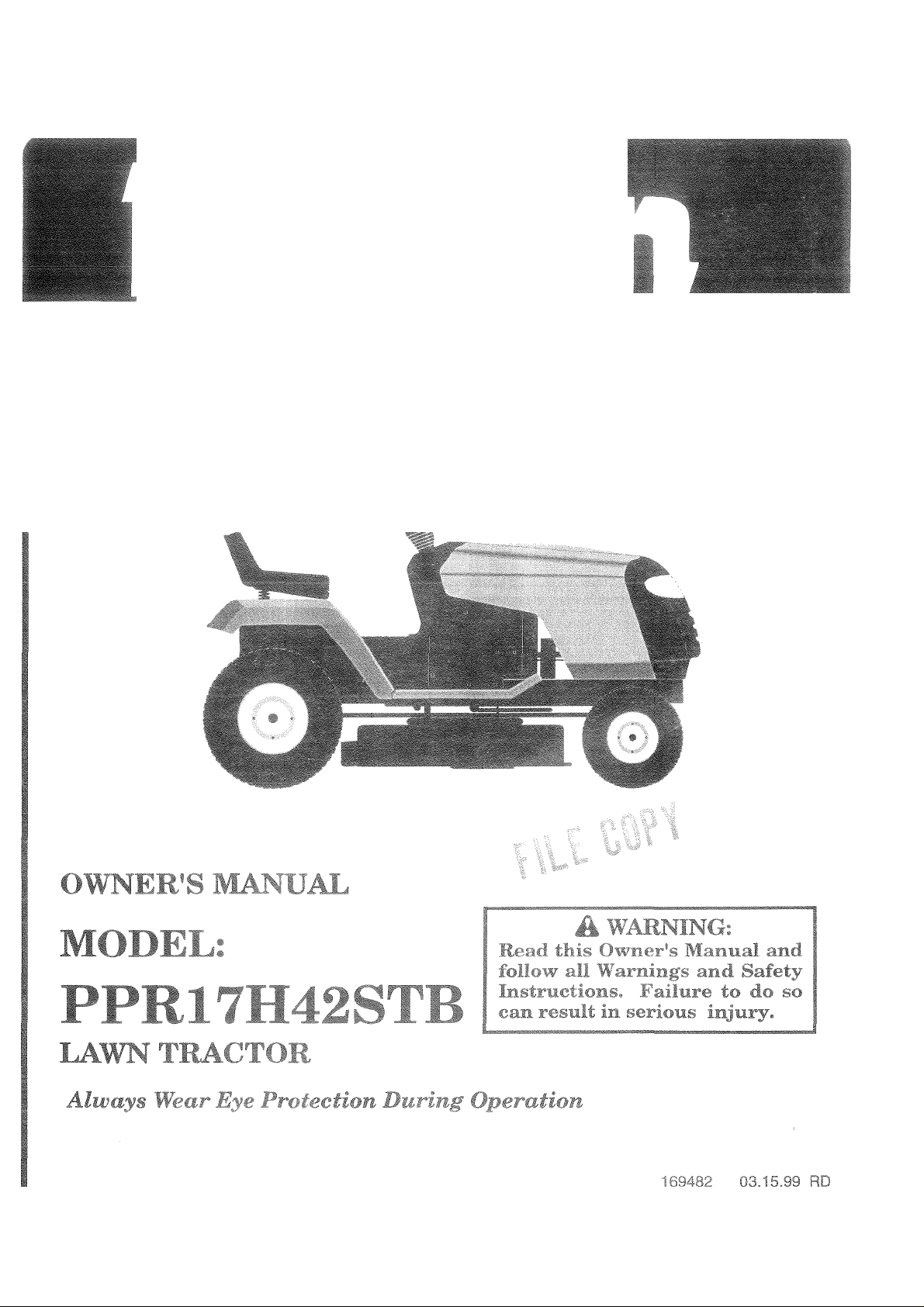
PPR17H42STB
DATE OF PURCHASE _________________________
THE MODEL AND SERIAL NUMBERS VTILL BE FOUND ON A
PLATE UNDER THE SEAT,
I YOU SHOULD RECORD BOTH SERIAL NUMBER AND DATE OF
* PURCHASE AND KEEP IN A SAFE PLACE FOR FUTURE REFER-
ENCE,
CUSTOMEP HEspori-IBliJTPES
• H-i>id ft- I ft- f'o tu'
* FullfWr lecjijlrj' rr^diiF m t int jiiiiriO caring for and
using your iracior.
« Fo!!o'A'th8 instructions underthe “Customer Responsibili
ties" and “Storage" sections of this owner's manual.
111! if
WARNING; This tractor is equipped with an internal combustion
► Pf'IPif'ATiflMÇ
engine and should not be used on or near any unimproved forestcovered, brush-covered or grass-covered land unless the engine's
exhaust system is equipped with a spark arrester meeting appli
cable local or state iavt/s (if any). If a spark arrester is used, it
should be maintained in effective working order by the operator.
In the state of California the above is required by law (Section
4442 of the California Public Resources Code). Other states may
have similar laws. Federal laws apply on federal lands.
Page 4

i mmu ^
1 he Manufac
materials and
repair or repl;
defective due
1. This wai
iraristTii;
a Uiim
2. ! ilJ!‘ I i.K ,! I t It'O ^ u r ihe ■ ij n* t f &| i 'wei cqi pni* t.i ur it ui ^ f Ti m < tl i :p nsibiiiiyci
hit u i ! t if ,y ,._r s ¡ ubn'. ed i_i r4''-. i-ri unr-^ u i ira,,tv'imja
pa, Í b i!|^ I in ti ^>Li.U-m i'jfhi tuio i: qi ' ' ted hy Fn jid oíh Hw n ni'u>t' il i'i-n,v''r--c^ E't.r,
niy uu
)il COfT
rnariuf
to the 3ngitiül cons>umer purchaser that this product as mans
eriod of two (2) years from d ate of pur T'lase by the orig
For 3 p
tion, witf îOUI CnSiQ© for parts or iabo
workma nsfiip. This /Varranty is subje ;t to the fc
It . .p..
ents, b£
rer's wa rranty on tf
y to the er gin©, other tha 1 FHP (F
ittery (exce pt as noted be
lese items.
r incurrec in replacing par tSj any p
liowing iimitation 3 and exc
1 1 / V ' _ 1
ow) or C(
jmpcnents part it C 11-
jfactured
inal cons
1 /111
is free from defects in |
umer purchaser, we will
art which we find to be
lusions.
1.1 1 1 i. a 1 '
F. W t T
d 1 :ui . VvTiiji , u i prjdi t -t. ill pi ’ "'lb - I- lit "V, .''0 *'iF u'"I- ii .uifh .vi rn .u , / t.-.tieiy
v.iiuli •' .in I 1 d ,3(f c Ti 11 I '»1 I 1« !' it j 'Pf hi b < hi ¡ y- t«*n. r^h.i Af'i ihreiv (’Xi)
.i.' V. nil I I, ibt b T'-, •‘n ' ,i 11 I n- f 1 i.f A’L atf ry im esni 0 II in .,i*h from
n ■- .fa 1. |i 'I I' t t > r ■ n 'i in+a ned m rd f r<j Ayth tF 'nsftU'‘h:,|i« luinrneu
4 f I Sb .f, fif' f (1 vl f. I I!/ p,' hj I' u -,i t~i rental oi n . uetcui ourposti is limitad to 90 Jay' Irom the
aaie or original purcriase.
5. This Warranty applies only to products which have been properly assembled, adjusted, operated, and main
tained in accordance with the instructions furnished. This Warranty does not apply to any product which has
been subjected to alteration, misuse, abuse, improper assembly or installation, delivery damage, or to normal
wear of the product.
6. Exclusions: Excluded from this Warranty are belts, blades, blade adapters, normal wear, normal adjustments,
standard hardware and normal maintenance.
7. In the event you have a claim under this Warranty, you must return the product to an authorized service
dealer.
Should you have any unanswered questions concerning this Warranty, please contact:
...... j * In Canada contact:
Fngidaire Home Products
Outdoor Products Customer Service Dept. Frigidaire Home Products
250 Bobby Jones Expressway 7075 Ordan Drive
Augusta, GA 30909 USA Mississauga,- Ontario
L5T 1K6
giving the model number, serial number and date of purchase of your product and the name and address of the authorized
dealer from whom it was purchased.
THIS WARRANTY DOES NOT APPLY TO INCIDENTAL OR CONSEQUENTIAL DAMAGES AND ANY IMPLIED WARRAN
TIES ARE LIMITED TO THE SAME TIME PERIODS STATED HEREIN FOR OUR EXPRESSED WARRANTIES. Some areas
do not allow the limitation of consequential damages or limitations of how long an implied Warranty may last, so the above
limitations or exclusions may not apply to you. This Warranty gives you specific legal rights, and you may have other rights
which vary from locale to locale.
This is a limited Warranty within the meaning of that term as defined in the Magnuson-Moss Act of 1975.
5
;5
!6
«
i5
Page 5
Page 6
I V I i
IX me
ic
m f
*Un f
111 mafc
i I ! , 'tin ! r ol’el I ♦”«r' I II
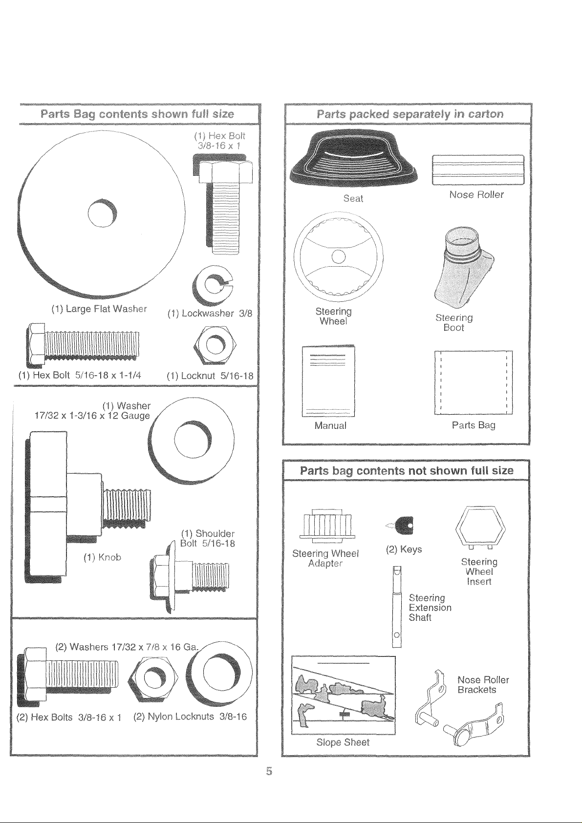
(1) 9/16" wrench Tire pressure gauge
assemb
SEMBLY
isier. Standc
ith ©xcoption of the
parts and hardwai
(2) 1/2" wrenches Phillips Screwdriver
T'l, ii -j1 I f'; ft 1 i;d IS Tr-idioneo in this nianudi, u
r. wh'.'O > ' (I PC >f-erating position (seated
behind the steering wheel).
r. Vf ‘ nf N 1HB FROM CARTON
UNPACK CARTON
iVi.-ct, j le !vo..e parts and parts cartons
iro'ii cu'-Tn >' I - I :ge 6)
» 1 >Jl top to .
. 1
It irri, along lines on all fourcorners
.ji I and bv i aneis ilaf
Check for any aduilional loose parts or cartons and
remove.
BFFriRE NCLL!NO TRACTOR OFF SK!D
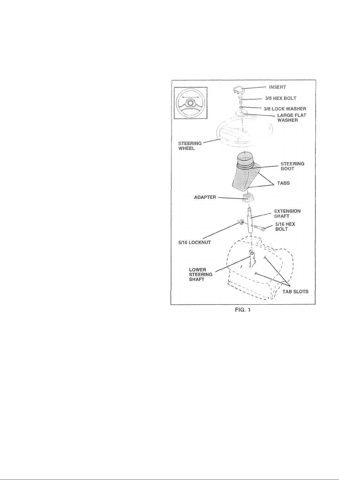
AT WHEEL (See Fig. 1)
CP .“r./i,( L , * rPN" ION SHAFT AND BOOT
nto lower steering shaft. Align
-iT >'! ( !.■ It IP extension and lower shafts and
>> t-il-'o ti‘ '■noil rd locknut. Tighten securely.
!MPOH4Wr ir^TFN BOLT AND NUT SECURELY TO
18 2 r I ! p ' I' [-fjilb
' O.'rtT ’ ♦'» iri'j boot over tab slots in dash and
o •'!! d>N/ i m uri
INWALL ^TEflilNfi WHEEL
• Posi.k pfrontwnceis of the tractor SO they are pointing
straight forward.
® Slide steering wheel adapter onto steering shaft exten
sion.
• Position steering wheel and sleeve assembly so cross
bars are horizontal (left to right) and slide onto adapter.
• Assemble large flat washer, 3/8 lock washer, 3/8 hex
bolt and tighten securely.
• Snap steering wheel insert into center of steering
wheel.
• Remove protective plastic materials from tractor hood
and grill.
IMPORTANT: CHECK FOR AND REMOVE ANY STAPLES
IN SKID THAT MAY PUNCTURE TIRES WHERE TR.ACTOR
IS TO ROLL OFF SKID.
Ills left ufias jled'
OU i ITlL
tiqh
TO ROLL TRACTOR OFF SKID (See Operation
section for location and function of controls)
• Press lift lever plunger and raise aitachment lift lever to
its highest position.
• Release parking brake by depressing clutch/brake
pedal.
» Place freewheel control in freewheeling position to
disengage transmission (See “TO TRANSPORT" in
the Operation section of this manual).
• Roll tractor forward off skid.
® Remove banding holding discharge guard up against
tractor.
Page 7
^SSE^BLY
TO SET UP YOU
R TRACTOR
EClC BATTERY (Ss© F
Lift sost p3ii to rsisod posiîi
If tîiLb uau6ry IS plii II1ÏO SQpJ
in 1 or. ' ib< 1 'M■ ' ated between terminals)
oh. ,gfc bati-.’'» iOi il 1,11,.
(S-e"BATn FtC'iiT 1 ‘ ■
smtion of this matiM » c h
TERMINAL
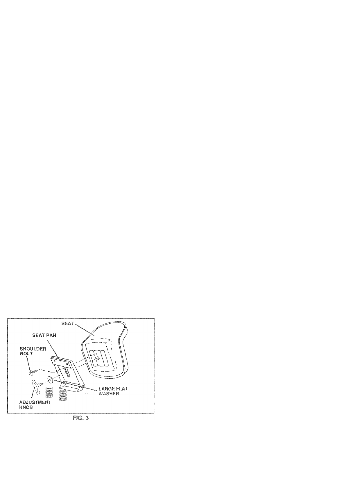
Adjust seat before tightenir.g adjustment bolt.
® Remove cardboard packing on seat pan.
» Place seat on seat pan and assemble shoulder bolt.
Tighten shoulder bolt securely.
* Assemble adjustment bolt, lock washer and flat washer
loosely. Do not tighten.
* Lower seat into operating position and sit on seat.
• Slide seat until a comfortable position is reached which
allows you to press clutch/brake pedal aii the waydown.
• Get off seat without moving its adjusted position.
® Raise seat and tighten adjustment bolt securely.
cn Hnd opon bsttory box
<ce after month and year
)f one hour at 6-10 amps.
lER RESPONSIBILITIES
arging instructions).
rO ATTACH NOSE ROLL!
Position bfârkBts 17/32 X 7/8 Î
c Fla. 41
X I o gauge wasners,
¡nting brackets as she
n correct side, as she
hex b
lien uc
■^OTî I • U> I r (I . loi, i' -.'lU t !l. , Ii 'h ItS n
lOr'lrf"
TAB HOLE-
I'd
nd 3/8-11 li nuts
I I \ -S'F r TAB
>L\ M
>c<l
^ \
..OCK MUT
Û m ~
' WASHER
CHECK TIRE PRESSURE
The tires on your tractor were overinflated at the factory for
shipping purposes. Correct tire pressure is important for
best cutting performance.
• Reduce tire pressure to PSI shown in “PRODUCT
SPECIFICATIONS” on page 3 of this manual.
CHECK DECK LEVELNESS
For best cutting results, mower housing should be properly
leveled. See “TO LEVEL MOWER HOUSING” in the
Service and Adjustments section of this manual.
CHECK FOR PROPER POSITION OF ALL
BELTS
See the figures that are shown for replacing motion and
mower blade drive belts in the Service and Adjustments
section of this manual. Verify that the belts are routed
correctly.
CHECK BRAKE SYSTEM
After you learn how to operate your tractor, check to see
that the brake is properly adjusted. See “TO ADJUST
BRAKE” in the Service and Adjustments section of this
manual.
Page 8

jctions have been completed.
•e parts in carton.
hOU;
IS propt
it 6 aiTif
adiustec
prepared and charged. (Minimum
omfortabiy and tightened securely.
/ All tires are properly inflated. (For shipping purposes,
the tires were overinflated at the factory).
!*,'■ c> * II •' < t i I I ' a d aiif-to =|fir/
front-to-rear for best cutting results. (Tires must be
properly inflated for feveling).
' wh. t i-m; i.. flit/, h I* tc s.j'Pilityaie louied
pr ;• I i/ '(.UM.iiu -y. nil i ide ail bed bee,lets
,, ( t*. ij. v/!iir\. r,oe ifia«..III m licri.ons ate still secure
jiic tAj.reo to propc iy f i.u «}> d
F.' f 0M\M‘J c rr1np bi’ uti tree v-hei-'Lf nti'-i It in
drive position.
Vi/Hli L _ flfv «h/m/yoi.1'70 .,7. f iUURli \CTOHjAf
LXV, / • rtk '/•/ fv ?/,T LOWINC ,.MFOhlANT
:TEM‘
/ Engine oil is at proper level.
/ Fuel tank is filled with fresh, clean, regular unleaded
gasoline.
/ Become familiar with all controls - their location and
function. Operate them before you start the engine.
/ Be sure brake system is in safe operating condition.
/ It is important to purge the transmission before operat
ing your tractor tor the first time. Follow proper starting
and transmission purging instructions (See “TO START
ENGINE” and “PURGE TRANSMISSION” in the Op
eration section of this manual).
8
Page 9
OPERATION
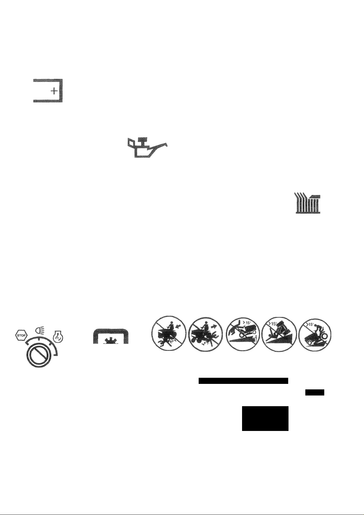
These symbols may appear on your tractor or in literature supplied with the product. Learn and understand their meaning.
1
f
BATTERY
CAUTION OR
WARNING
STOP
REVERSE FORWARD FAST
©
ENGINE ON ENGINE OFF OIL PRESSURE LJGHTS ON
iS l\l
FUEL
CHOKE MOWER HEIGHT PARKING BRAKE
f
SLOW
G= ©1
OVER TEMP
LIGHT
Ik
if
©
UNLOCKED MOWER LIFT
LOCKED
i
is* NHL
ATTACHMENT REVERSE
CLUTCH ENGAGED
ATTACHMENT
IGNITION
DANGER, KEEP HANDS AND FEET AWAY
CLUTCH DISENGAGED
m
NEUTRAL HIGH LOW
♦
KEEP AREA CLEAR SLOPE HAZARDS
PARKING BRAKE
(SEE SAFETY RULES SECTION)
h-'■ =/<éím
FREE WHEEL
(Automatic Models only)
Page 10
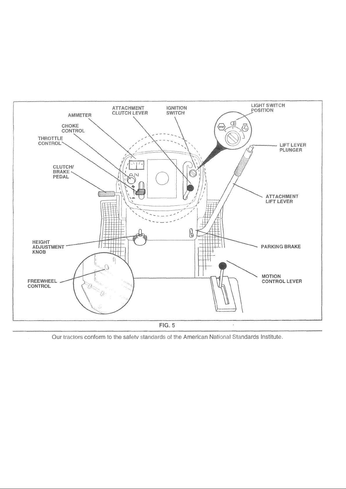
KNOW YOUR TRACTOR
CHOKE CONTROL: Used when starting a cold engine.
FREEWHEEL CONTROL: Disengages transmission for
pushng or towing the tractor with the engine off.
ATTACHMENT LIFT LEVER: Used to raise and lower the
mower deck or other attachments mounted to your tractor.
LIFT LEVER PLUNGER: Used to release attachment lift
lever when changing its position.
IGNITION SWITCH: Used for starting and stopping the
engine.
HEIGHT ADJUSTMENT KNOB: Used to adjust the mower
height.
AMMETER; indicates charging (+) or discharging (-) of
battery.
10
Page 11
^ ^ IP
3ms
L
tiom rc: ii“.t
TO •’ PâFsHMG DP‘r r I',, riQ g,
* Depress clutch/brake pedal into full “BRAKE” position
rtid hi.i( ,
» HiCi-p'fhiiqi'i ■! •' ■ i ii ‘ r'li> (»nsifiond'id
'f i-j tptfc lit' Iλ f' !»*■ d't ■' E il'd l t dri!; iiOiild
remain in “BRAKE” position. Make sure parking brake
v/!il t ;kJ ’ _ I >
fV
N< Ft Hi''' r • f t,., iivf'i'r r w-u-i . ' i'_ - I
idle with the engine running, hot engine exhaust gases may
Cv.,1' • r, f. ii _ I (■' . '.I ‘->i j (tiiliL,
always stop engine when stopping tractor c-n grass areas.
C ■ T r !> 'R AlAfnyz ‘ lt>r fri *: k, |
A
|j| Skv ,Lcf.jit 1er.-' f
Viti tht .trT-m''' r.fj'it'or tr f
gras
‘tCKtr rfr
TO I/' L ' O ^ iOf^ Rii. |Oee Fig b|
Aiwav' t -.If- fci'pirr dt full V rattle
“ r -iijiiie 'si less ih.in full throttle reduces the
b t(( I y I rid..'fing rate.
® Full throttle offers the best bagging and mower perfor
mance.
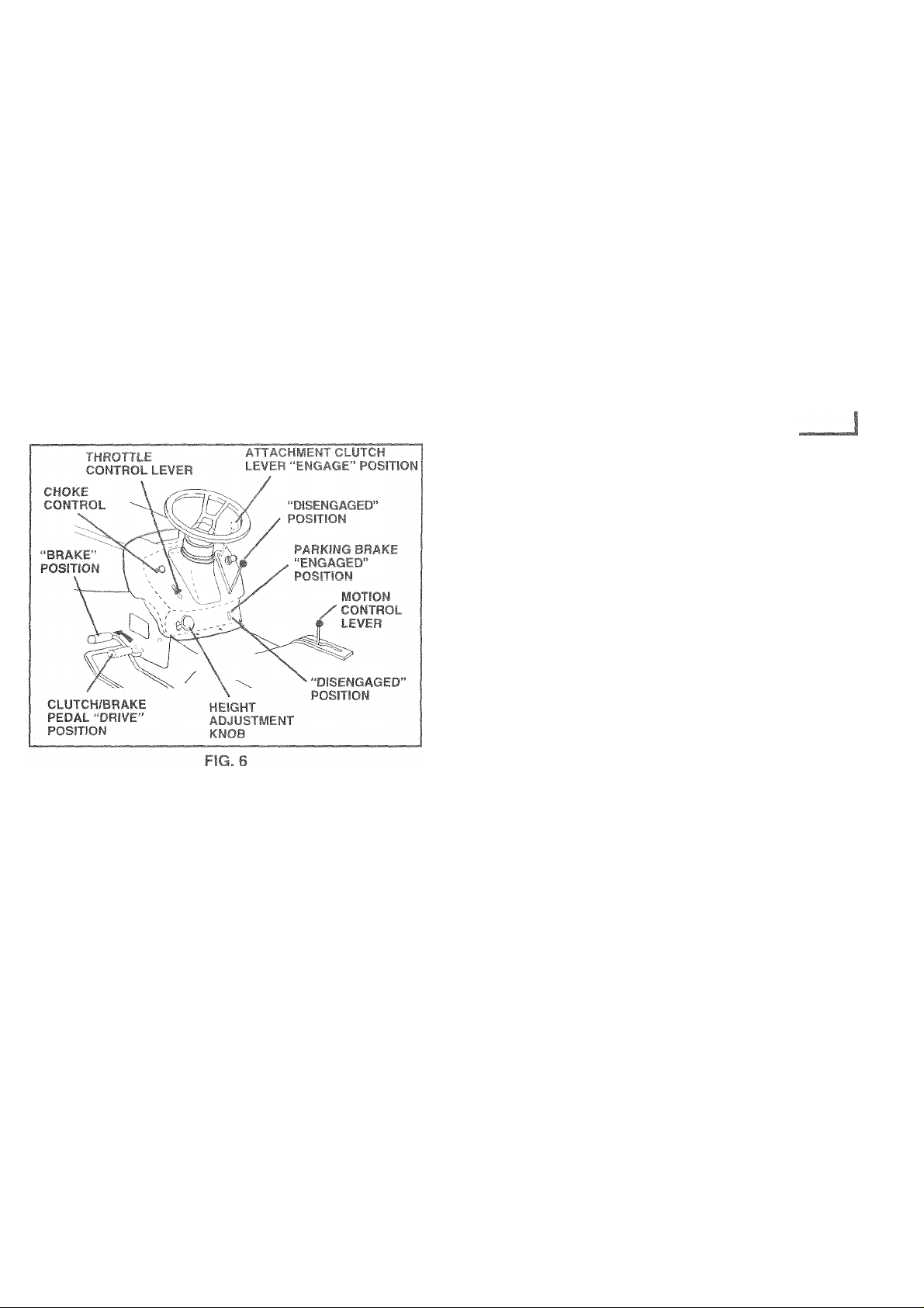
TO ‘ Hi AF CONTROL (See Fig, 6|
Usec'K i- conlnilwhi nfv‘-rvou ire starting a cold engine.
Do n('t I r TO tarf. warn, ''noine
• T' ct>'W coniro! pull knob out. Slowly push
knob m lo disengage.
STOPPING (See Fig. 6)
MOWER BLADES -
• To stop mower blades, move attachment clutch lever to
“DISENGAGED" position.
GROUND DRIVE-
• To stop ground drive, depress clutch/brake pedal into
full “BRAKE" position.
• Move motion control lever to neutral (N) position.
IMPORTANT: THE MOTION CONTROL LEVER DOES
NOT RETURN TO NEUTRAL (N) POSITION WHEN THE
CLUTCH/BRAKE PEDAL IS DEPRESSED.
ENGINE -
• Move throttle control to slow position.
NOTE: Failure to move throttle control to slow position and
allowing engine to idle before stopping may cause engine
to “bacWire”.
• Turn ignition key to “OFF" position and remove key.
Always remove key when leaving tractor to prevent
unauthorized use.
• Never use choke to stop engine,
IMPORTANT; LEAVING THE IGNITION SWITCH IN ANY
POSITION OTHER THAN "OFF" WILL CAUSE THE
BATTERY TO BE DISCHARGED, (DEAD).
TO MOVE FORWARD AND BACKWARD
(See Fig. 6)
The direction and speed of movement is controlled by the
motion control lever.
• Start tractor with motion control lever in neutral (N)
position.
• Release parking brake and clutch/brake pedal.
• Slowly move motion control level to desired position.
TO ADJUST MOWER CUTTING HEIGHT
(See Fig. 6|
Tne cutiirig ne.qtit is eonirelied by turning the height
aojustnient knob iii desired direction.
• Turn knob clockwise ( AK) to raise cutting height.
• Turn knob counterclockwise (Km) to lower cutting
height
The cutting height range is approximately 1 -1/2" to 4“. The
heights are measured from the ground to the blade tip with
the engine not running. These heights are approximate
and may vary depending upon soil conditions, height of
grass and types of grass being mowed.
• The average lawn should be cut to approximately 2-1/2
inches during the cool season and to over 3 inches
during hot months. For healthier and better looking
lawns, mow often and after moderate growth.
® For best cutting performance, grass over 6 inches in
height should be mowed twice. Make the first cut
relatively high; the second to desired height.
11
Page 12
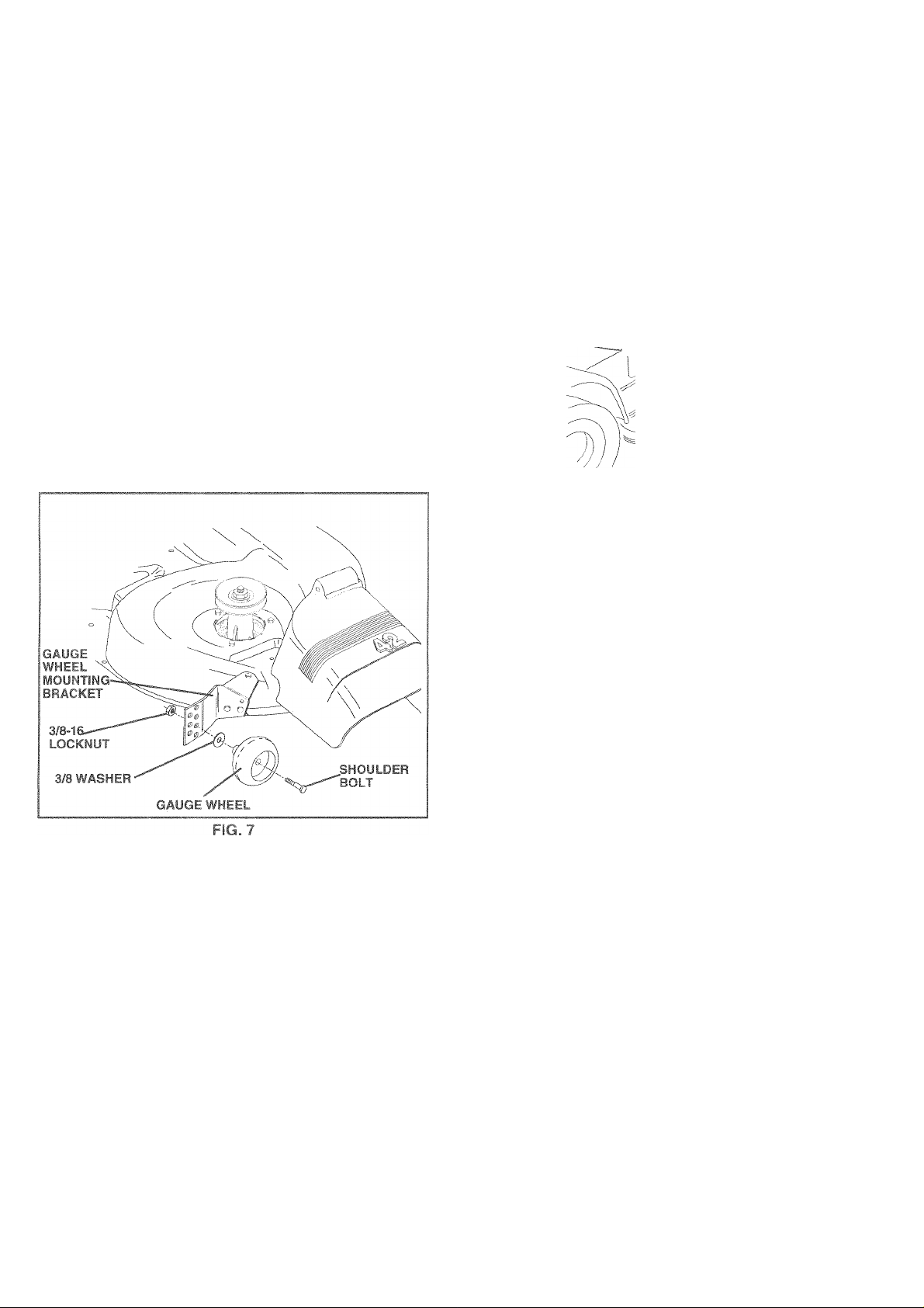
Adjust gauge wheels with tractor on a flat level surface.
Adjust mower to desired cutting height (See “TO AD
JUST MOWER CUTTING HEIGHT’ in the Operation
section of this manual).
With mower in desired height of cut position, gauge
wheels should be assembled so they are slightly off the
ground, install gauge wheel in appropriate hole with
shoulder bolt, 3/8 washer, and 3/8-16 locknut and
tighten securely.
Repeat for opposite side installing gauge wheel in
same adjustment hole.
T
TO OPERA! fc ON HiLLO
CAUl ICjii |J.< itoidriv'* «Jp oroown hills
'viir? y »id do not
a
dli.U M lOsb 'iMi, cluf-
LOW
POSITION
/ ;
\ /
r ii »
TT OPLG J r. (y Frfi 51
Yourtractor is equipped with an operator presence sensing
switch. Any attempt by the operator to leave the seat with
iht i.yvii ru.ii ii'i ana iti tm h centciuGh engt y-d «ill
shut off the engine.
• f-'' c das V c t c igtr >t cut.
• L IV-/hiGvv_i rfitn ditf'Jimeni lift control.
r-nn1
A,
■««fr blades engaging attachment clutchbiar
ES - disengage attachment
CTUTitTi Dr riot operate the mower
wiihc-m pi'iier "he entire grass catcher,
on mowers so equipped, or fire dis
charge guard in place.
C l.cor
hll£
» Avoid stopping or changing speed on hills.
• if slowing is necessary, move throttle control lever to
slower position.
• if stopping is absolutely necessary, push clutch/brake
pedal quickly to brake position and engage parking
brake.
® Move motion control lever to neutral (N) position.
IMPORTANT: THE MOTION CONTROL LEVER DOES
NOT RETURN TO NEUTRAL (N) POSITION WHEN THE
CLUTCH/BRAKE PEDAL IS DEPRESSED,
• To restart movement, slowly release parking brake and
clutch/brake pedal.
® Slowly move motion control lever to slowest setting.
• Make all turns slowly.
til .nwesi spe. d bt to: darting up or down
TO TRANSPORT (See Fiqs. 5 and 9)
When pushing or towing yourtractor, be sure to disengage
transmission by placing freewheel control in freewheeling
position. Free wheel control is located at the rear drawbar
of tractor.
® Raise attachment lift to highest position with attach
ment lift control.
® Puli freewheel control out and down into the slot and
release so it is held in the disengaged position.
• Do not push or tow tractor at more than two (2) MPH.
• To reengage transmission, reverse above procedure.
NOTE; To protect hood from damage when transporting
your tractor on a truck or a trailer, be sure hood is closed
and secured to tractor. Use an appropriate means of tying
hood to tractor (rope, cord, etc.).
12
Page 13

OPERATION
TC dPr' W'f,,
‘ ' V ,ui4 'i' r f ■ 1
CO !lf 1/ Viitfi p • ill , 1,1 . f the
tidCtct U.t, • hi-,’>ii >- f/nsn I owing. Too heavy of a
load v.hilc jIi -'op, '1 <srous.
with the fjiou !.:.>■
tra tor BEt ‘jfi A ' ‘ " i‘ THE E
• The engine in your tractor
factory, already filled with■ sumrner weight oil.
• v,ntT * igi 1, 1 ■■ fli i
• f-.j 1 lO't, 4 111 , '•> , * !
dipJic !■ in 1 1- ft/ 4 '1
“FiitJ ..»fi 1. w
t ,j i( >11 -1 Ri- r ,'i H H -
* 1 0 rill IU<- I'jl' H ' 1
1
CHECK miyjyi • ’ nE¥El
tem^cw err r 1 [ v.
• t O' cold : -ih 1 HI } 11 y O L
esiit' H-n'ti' ('■ ' IL VISD
THE! 3 attachments
it are
you tc
recommended by and
manufacturer of your
Ilf 1 r l> n,t cn
) lose control of your
ENGINE
. (See Fig. 14)
)een shipped, from the
has t
)!or or 1 level grourrd.
c and ^vipe clean, reinsert the
□ntf w
L if n I - m - J 1 111 til
s reac
3 S0
^ the Ctostomer Responsibili-
ait for a few seconds,
1 - (1 ') r/ 1 j nil.
" !l|t 11
1
tj ' 1 4 *Or
! ! ' ‘ Ì toPl in ¡ne
Ction of this mariuai).
ADD GfcbWt :r-F
» r ill 'Ut' > 1 i 1 t
'Id-' III i ' 'll . >f. Jf,
gasoline will increase carl
and reduce valve life). C
Purchase fuel in quantitie
(’ . . ) .TO - II 1 ‘ ’ >
IMP T.t .|i t . i r ^
tj F ' W A f 4 1 [ 1 ’ 1 ÌH, CL.EAN WINTER GRADE
CA-i 1 INF TCi 1 E 1 F W >'■ E GO OD COLD WEATHER
STARTING.
WARNING: Experience indicates that alcohol blended
fuels (called gasohol or using ethanol or methanol) can
attract moisture which leads to separation and formation of
acids during storage. Acidic gas can damage the fuel
system of an engine while in storage. To avoid engine
problems, the fuel system should be emptied before stor
age of 30 days or longer. Drain the gas tank, start the
engine and let it run until the fuel lines and carburetor are
empty. Use fresh fuel next season. See Storage Instruc
tions for additional information. Never use engine or
carburetor cleaner products in the fuel tank or permanent
damage may occur.
h, eie an, regular unleaded
fi7 f)
Don ar
to not mix oil with gasoline.
less.
WING .1 11 v4 rf r RiPLS
i iip. I'i' ‘ i.i 1« Fed
id lead oxide deposits
rpo ,II . ,j / ||ri|,| 30
p A UTION* Fill tc
filter fiscic» Do not
ik
"A
When starting the engine for the fi
has run out of fuel, it will take extra
fuel from the tank to the engine.
• Be sure freewheel control is in the transmission en-
uOa^J uuoluo.,.
i -It - , ^ d ‘ *p'-i p •; h I I* I < Imi ììI,h i <
I <• I , j, i 1,1 ( h r <-
® P!ac0 motion control lovor in neutral (N) position»
• Move attachment clutch to “DISENGAGED” position.
/1
' ' ihr 'riU -f ' ti jl ( cti 4 f
NOTr* Pel ,r» »iliii'p i--'d ih_ V.» "0 =r ^ Ir i'nrtmg
pro- ( dt>t. L : lA/
e 111'cdl-i-y ifif r r|oc,i >'r'eti 'FARF'
,/i ti II rcj*tl( ISC ‘-'m soon -‘.f in tort' nri
h .1 ri. . t n-r t Oil* r Jl U''! • f( i iiioro lh,.n lifiP ri tc-
, , V ^ - 01,If F .-r.ijni; 1 "Ijp »ftt-r
f, fi if 'ttf-ifìfis muM th cttleconir j| to toM po-itrr,
V'-It ^ wminutf " anf’iry ?qc-in itemjin»- itiildot noi
•ton move rhe throttle coi.troi sack >o th ■ kc
position and retry.
WARM WEATHER STARTING (50“ F and above)
• When engine starts, move the throttle control to the fast
position.
• The attachments and ground drive can now be used, if
the engine does not accept the load, restart the engine
and allow it to warm up for one minute using the choke
as described above.
COLD WEATHER STARTING ( 50° F and below)
• When engine starts, allow engineto run with the throttle
control in the choke position until the engine runs
roughly, then move throttle control to fast position. This
may require an engine warm-up period from several
seconds to several minutes, depending on the tem-
• Before driving the unit in cold weather, the transmis
sion should be warmed up as follows:
• Be sure the tractor is on level ground.
• Place the motion control lever in neutral.
Release the parking brake and let the clutch/brake
slowly return to operating position.
• Allow one minute for transmission to warm up. This
can be done during the engine warm up period.
• The attachments can also be used during the engine
warm-up period after the transmission has been warmed
up.
NOTE: If at a high altitude (above 3000 feet) or in cold
temperatures (below 32 F) the carburetor fuel mixture may
need to be adjusted for best engine performance. See “TO
ADJUST CARBURETOR” in the Service and Adjustments
section of this manual.
>line near an open flame
JGINE Fit
3iTi of oas tank
Hfl
me or if the engine
nkinci time to move
Page 14

OPERA
Ш
Il ¡I
“'PAài^
ài
insure proper of
ided that the trai
tor for the first t
ipBU dJi líldlüí
d duririq shit
ope
IMP
DRTAN1
REf
MOVAL FOR SERVICE OR REPLACEMENT, IT
OULD BE PURGED AFTER REINS FALLATION
FORE OPERATING THE TRACTOR,
ng of your tractor.
)ULD YOURTRANSMISSION REQUIRE
-I 16 \ !trV " ‘' r i* ' ^ iV'if’ ' f I" .c if snri
parking brake set,
L'i - I'O - %>i h'i'iL-n by I k( ing iir‘HidMiOi
.1. n V, ,! ||D pj. iti-.n (Sf€ TO t“F vT- .F f in
this section of rrianuaS).
I'‘ , III'. ii'H .!• i ,,i iichn ‘ !c//j iti,,i 'Vith
n i' F,t,' II i •' !(' itrai (Hi pc ifi i „'owlv
Hm
Nk ' - irbhoi" coii*i.)l • a I to full tor^/ard (. CA.tian and
fi'dii for b/- d • '.iH.T Mova if/ei to full reverse
C dior . r. ‘ hoiR ‘f,i fivt (5) recimds heor О this
¡‘•r c-edure tf.iee (3) ¡rnes.
NOTE;: During this procedure there will be no rnovement of
drive wheels. The air is being removed from hydraulic drive
Move motion control lever to neutral (N) position. Shut-
ir ih.Oi i )i ,-rdt. ddilt igine /Ttrf ht f-ngine
¡I .r.
-fir
lance, It is recom-
d before operating
ili remove any
ay have devel-
iNi
cha
MOWGif sfiouiu be pre
nprfnr
pci iKJiтпапсе. See TC
The IiÍÍÍ hand side of mower should be
>periy leveled tor
) LEVEL MOV/ER
itfT^ents section of
Dest rnowino
HOUSING'" In
this ШЕП1Ш1.
used for trirn-
minq.
Drive
< Ti't . Hpf IIifi
that hi as been cut. Ha’
machi rie . hf ' "I
1 --lie ' 1 , '
clippir
Whon mowing large a
so thi 1 iifpit 0 V1.;
fence:
til L i Ve *■ ig •< ,
It grn-, r e/Tit-rnt Iv I-i| i „hr i
H a V if' T *
fadu. t- •' ili ..,d t 'VibC I'l' r.
p.iiy“- M-ik T|1 J J I I la. v-.lv r, qfi ih
s 3.re discfierQed
if- ^ Ut ’ T -• t' db Ц i
uli in a more even и Qi
1
liform cutting.
’1- • • *-[f, 41.liiMj t(. thr f rhr
i ' : 1И| _ n ^li /
¡f- r.i ^ ij 1 ^ j
LIT Î ! Оси Í 11 i (< i Ji 11ч Uííul
be îTüWfcd twicr to
il I irr n Tp-
|i Mi' CiUb ,
Il'ij'i'J, (now
¿w'iiu olht
df 'irej h''IOr.t
[>'. ru‘t iiicw 'jt-w 'vrv I i_ wuf t'/ i grj V will plug
nuUi I I id It .V.'jiidfcur.TlB j'lipi. ‘illcw Cjia,-s rc
n n f r>. "T rW H.n CV
l.,i) ii k.„/ i; \./' i 'i
.............
I(
..........
'■ ii '/ k :■ ;■ \..a ,■
Alw&V' opeiu’'-tngim ,i‘>J! itiH-ttlB wtien mo/tiing to
as:ijti betiei »n^wiry ptriC'iriaicfc ano propei disc!idiye c! ir=tferici F.egu.aie gtoLri j ipted by adeciing a I-w 'tivujgh ge^r L tjiva iL.t mower cutting
performance as well as the quality of cut desired.
When operating attachments, select a ground speed
that will suit the terrain and give best performance of
the attachment being used.
Engage transmission by placing freewheel control in
driving position (See “TO TRANSPORT” in this section
of manual).
Sitting in the tractor seat, start engine. After the engine
is running, move throttle control to halt (1/2) speed.
With motion control lever in neutral (N) position, slowly
disengage ciutch/brake pedal.
Slowly move motion control lever forward, after the
tractor moves approximately five (5) feet, slowly move
motion control lever to reverse position. After the
tractor moves approximately five (5) feet return the
motion control lever to the neutral (N) position. Repeat
this procedure with the motion control lever three (3)
Your tractor is now purged and now ready for normal
operation.
Page 15

MER RESPONSIBILITIES
; F j i i <• I 1 ! I 4 i 1 fi \ "-li
GENERAL RECOMMENDATIONS
The warranty'.n ihi-1'^rif.( d ) .•'»;_f iit; t itnrhwe
been subjected k opttJ > c.b‘' c u. n'^g'sjcnc > To
receive full vai'.cfrr* di* • pcr-'^t s'■us <in
tractor as instru- ted h it e in. riu !
Some adjustm^ nts will nt od tü be made peroucdl v lo
properly maintain youi ir. i lOi
All adjustment in th^ ' j ■ -.nu'id, i trr n.'s( ( ih n cf
this manual sh-tnl'i t, i r,^. » .imi t-'-f h - , on.
« Once a yeai /ou ^ h ik pk ' he ''■ean
or replace a.i filter, i ' i nei.K teon-. and bs i’ for
wear. A nev* spah ^ hn iitj ulea.i ai filie» . ' uie
proper air-fum mix Cc ci j i elp your engine run better
and last longer.
BEFORE EACH USE
• Check engine oi! level.
• Check brake operation.
» Check tire pressure.
• Check operator presence and interlock systems for
proper operation.
• Check for loose fasteners.
Do not overtighten,
LUBRiCATION CHART
©SAE 30 OR 10W30 MOTOR OIL
©GENERAL PURPOSE GREASE
©REFER TO CUSTOMER RESPONSIBILlTiES “ENGINE” SECTION
IMPORTANT: DO NOT OIL OR GREASE THE PIVOT POINTS
WHICH HAVE SPECIAL NYLON BEARINGS. VISCOUS LUBRI
CANTS WILL ATTRACT DUST AND DIRT THAT WILL SHORTEN
THE LIFE OF THE SELF-LUBRiCATING BEARINGS. IF YOU
FEEL THEY MUST BE LUBRICATED, USE ONLY A DRY, POW
DERED GRAPHITE TYPE LUBRICANT SPARINGLY.
15
Page 16

IQ úiSíSnCB
e adjusted,
ind Adjust-
j FLAT WASHER
¡LOCKWASHEf
in all tire
36 “PROD-
anual).
lime, oil, or insi
itrol chemi-
ubber.
Avoid stufTips stor ibjects and
other hazards that i may CBUS6 tire damage.
fE; To sea! tiTG purl' [ires due to
1? leaks, tire sealant 1 your local
Q d0£||0f T
pBil
corr
osion.
ERATORI PRES¡ENCE SYSTEM
OP
Be sure operalior pres
wo riking propelriy. if y
cribed, repciir the pr oblern immediately.
desi
Ire seaJc try rot and
'Stems are
unction as
The engineÌ should utch/brake
pedal is fu!i'
ydepres itch control
is in the die?enQaQG^3 position.
When the e
ingine is
tor to 1©3VC3 the se«
iiir hTkj iiiv t eriipi by the opera-
1 ,'ih' .r 'II..Í ‘•ctfing the parking
brskG shoulid shut c)ff the engine.
When the emoine IS m, lililí, nr. iii8 .Uachment clutch
is ©riQHQSd 3 leave the
seat shoulc
©
Qftor''Hr
J shut oil
nentclut 1 cl muid ne '-or operate unless the
f the engine.
operator ¡s in the se;at.
(C
*A GRADE 8 Hi
IDENTiFiED BÌ
line
3 BOLT CAN BE
D.
FIG. 11
ft I ' pr I-
in 11 /'■ f 111» I Mil.'
Jo, be sure the blade is b
dare should be taken to
Ul Ot
d blade will caus
The blade can b
wheel. Do not a'
alanced.
I - [ ip hi ,> ‘a Ian ,ed. An
a: fi.:, hi/■■mr;
h i'
lUt if you
id even-
grinding
mower.
• Pm bpf.t lio’lf h limn I >A u 'o!hi‘-^d 15/8" diameter
. ell'Mii, pill '>■ lm.i i ,il 111 pJii. n using acone
h .laric> . (OiPw th' m trui .n .ivpiied with bal
ancer,]
NOTE: Do not use a nail for balancing blade. The lobes of
the center hole may appear to be centered, but are not.
» Slide blade on to an unthreaded portion of the steel bolt
or pin and hold the bolt or pin parallel with the ground,
if blade is balanced, it should remain in a horizontal
position. If either end of the blade moves downward,
sharpen the heavy end until the blade is balanced.
ADE CAF
BL
For best result:
piac e bent or damageci
3 mower iharp. Re-
<.... „..,S......
UlciUGo,
BLADE REMOVAL (See Fig. 11)
DiSu6.
install D6
towards
iViANDREL ASSEMBLY.
> , ^ (nn Ik> L -vash'-i ^ lO t!.a* vvasher in
exact order as shown.
• Tighten boit securely (27-35 Ft. Lbs. torque).
access to
srsecuring
ig edge up
SEMBLY,
STAR OR
TREATED.
Page 17

BATTERY
iractc
■ ha
for П'
'H
riTic
jrger will
s clean.
narging
" I ( r II ‘ill '' lit t> I I
“ h ► ( r -.tyc t I •; h 1» r f I i li t>'.
N‘'^Tf fiO . Iiir, h .1 ■ _ .iprr.r, I 1 .it u(i< li ,r'^t t(.' ¡e
m.-mii^tiani - t'. - f' >ii i i' i i| :■ i.g.-iini* ri. i'*. i-¡o
or covers. Adding or checking level of electrolyte is not
he«'
rO • I Fah hai ir R 111 - fRRMINALif
Orrru-.cti if", j.i'uiioioo aerv and tenniodis uan cause
The >u ‘f j puvrei.
( ipfll i) 4ti-iV L,Ui JuCk.
Di*^(onrifc Kfi )l)ie first then RtD bat-
ti. r, I able all. iLt*i i~ itti ,y ii> rri 1ra< tc-i.
Rin-'6 tfic bitlef' vhi. tJdiii w 4c r and dcy
Clediitrrr|-.f,jj._,-[', f, . IjIj ends #ith wire brush
until bright.
Coat terminals with grease or petroleum jelly.
Reinstall battery (See “REPLACING BATTERY" in the
SERVICE AND ADJUSTMENTS section of this
manual).
V-BELTS
Check V-belts for deterioration and wear after 100 hours of
operation and replace if necessary. The belts are not
adjustable. Replace belts if they begin to slip from wear.
TRANSAXLE COOLING
The transmission fan and cooling fins should be kept clean
to assure proper cooling.
Do not attempt to clean fan or transmission while engine is
running or while the transmission is hot. To prevent pos
sible damage to seals, do not use high pressure water or
steam to clean transaxle.
® Inspect cooling fan to be sure fan blades are intact and
clean.
• inspect cooling fins for dirt, grass dippings and other
materials. To prevent damage to seals, do not use
compressed air or high pressure sprayer to clean
cooling fins.
rriCIP ED BEFORE
All- irjh T.iiii. v'l^. ' И, I
improve starting in cold weather, thes
wm iW/’i'etc.j
I.D-i' . >t/Ol'S
40'
II]
Vi/P r.»' ■! i>> iri'I : wi ,ih tb'¡tif 11't. wf.-n i =-.'1 nho''e
a, ' f fli T (I r^'igint n , bvO‘ lr>-|UM>iL't{- -/Old
pc- .bit 'I J .1 - Jr 1
1
l-i- ll ! I U ‘ !и|И. I jIi III
Cr. ncy 'he ml -,ць • eiyCdfiouv <! • f Jiic.h гч-i f-dSi
ипс' -j if ihr 1, , “-mu - !. 1 ,4 h ' i£ 'ч or ^ r.
Ch..,'.' the ■ r i-pi are nil R.tl of- or- doning 4ic •riigine
ar. f .лПы ' rtf riyfii (f! fiLbm t 'p 5 aucr Г jhmii ill fill
cap/'ip tiof fecuiely ЗЭ' you ■‘ht-tHhe oil Itvel.
TCfH-NGF FrJGINEfJiL i^ee^g 14)
[•emriT nt leirij-ii-iciiurumno-r t/pe JoJ before oil change
All Oil nibSi mefci Ar i .jcrvioe Lir-bDiiication SF, LG or SH
• Be sure tractor is on level surface.
• Oil will drain more freely when warm.
• Catch oil in a suitable container.
• Remove oil fill cap/dipstick. Be careful not to allow dirt
to enter the engine when changing oil.
• Remove drain plug.
« After oil has drained completely, replace oil drain plug
and tighten securely.
• Refill engine with oil through oil fill dipstick tube. Pour
slowly. Do not overfill. For approximate capacity see
“PRODUCTSPECIFICATIONS” section of this manual.
• Use gauge on oil fill cap/dipstick for checking level. Be
sure dipstick cap is tightened securely for accurate
reading. Keep oil at “FULL” line on dipstick.
TRANSAXLE PUMP FLUID
The transaxle was sealed at the factory and fluid mainte
nance is not required forthe life of the transaxle. Should the
transaxle ever leak or require servicing, contact your near
est authorized service center/department.
ENGINE
LUBRiCATiON
Only use high quality detergent oil rated with AP! service
classification SF, SG, or SH. Select the oil’s SAE viscosity
grade according to your expected operating temperature.
17
Page 18

^leaner aft
MCD OETOOi
n dried qum
dush
iflO
"R\/l
DcIlUidie II II
doth and so'
® Clean cartridge by tapping gentiy on flat surface. If very
IE4dLEANER
UicI dotergen! and water.
ry in a clean cloth.
engine on. Wrap it in Ci0c
jeeze to remove excess oii
r damaged, replace pre-cle
iRT'RIDGE
abeoiLefii
tnr r.
iirn- i t mill ig d r I. • , [ rings
® Reinstall precleaner cartridge, cover and secure with
M lUUS.
IMPORTANT; PETROLEUM SOLVENTS, SUCH AS
KEROSENE. ARE NOT TO BE USED TO CLEAN THE
CARTRIDGE. THEY MAY CAUSE DETERIORATION OF
THE CARTRIDGE. DO NOT OIL CARTRIDGE. DO NOT
USE PRESSURIZED AIR TO CLEAN OR DRY
CARTRIDGE.
ENGINi
Ftemove any dust, dirt or oi! from engine cooling fins to
0 1
m iioinii' 1 -I , ' I
. 5
! I
/ 1
■! eE 1 . £ i ! 11.' ' ( I i( I r - ' . I • I . 1 [I ' ■ I ,H,i J I it , i ‘
REMOVE HOOD AND GRILL ASSEMBLY” in the Service
and Adiustments section of this manual).
T' PAIR
GUIDE rOVFR .
1
ENGINE
COOLING FINS
r;J ^
, '•« I
ri
"8
FIG. 16
Page 19

c? i '■ mtH m i
3r and spark arrester (if
lazard and/or damage.
SPARK PLUGS
Replace spark plugs at the beginning of each mowing
season or after every 100 hours of operation, whichever
occurs first. Spark plug type and gap setting are shown in
“PRODUCT SPECIFICATIONS” section of this manual.
IN-LINE FUEL FILTER (See Fig. 17)
The fuel filter should be replaced once each season. If fuel
filter becomes clogged, obstructing fuel flow to carburetor,
replacement is required.
• With engine cool, remove filter and plug fuel line
sections.
• Place new fuel filter in position in fuel line with arrow
pointing towards carburetor.
• Be sure there are no fuel line leaks and clamps are
properly positioned.
• Immediately wipe up any spilled gasoline.
FIG. 17
CLEANING
• Clean engine, battery, seat, finish, etc. of all foreign
matter.
• Keep finished surfaces and wheels free of all gasoline,
oil, etc.
• Protect painted surfaces with automotive type wax.
We do not recommend using a garden hose to clean your
tractor unless the electrical system, muffler, air filter and
carburetor are covered to keep water out. Water in engine
can result in a shortened engine life.
19
Page 20

Mm
II I^TiiFM
ME
10 liisciss Slid nil iTiovinQ psrts li3¥B corfipi&id^ stoppsd»
»park plijci wire from spark plug and place wire where it cannot con
,1 IFl .'ivr .ftiii.'.p
TRACTOR
TO REiJQ¥E MOWER (See Fig. 18)
Mower will bo easier to remoyefronrlhe ri*^ht side of tractor.
• Place attaenment clutch in “DiSEMGAGED” position.
I ' .lii [ «3 "E r ‘li / eF 'y eTeO rr» ' O eO
Roll belt off engine pulley.
■ .E ,EH, w > I I I i-.... dEjicIi W/ei t'i/ lamo'/irq
retainer spring.
removing retainer spring.
i:vw! i’-u '.licpersioi, .000? irt«rn rti.it dwh bfa>'’kri3
by removing retainer springs.
uisGonnect front Iihks from deck by removing retainer
springs.
Raise lift lever to raise suspension arms. Slide mower
out from under tractor.
IM
MC
RE
TO
-EititA-E Lwr ‘.nn, i,bas.sic b‘3i^ket ov
- AN ATTACHMENT OTHER THAN THE
BE MOUNTED TO THE TRACTOR,
ONT LINKS.
iOWER (See Fig. 18)
lent lift lever to its highest position,
nder tractor with discharge guard to right
' ; mn,h hOD
CLUTCH LEVER
' ;r I o.-. <:
,FILIN'
FIG. 18
r to its lowest position,
n reverse order of removal instructions.
20
Page 21

<s I . fi/j) ijifM, ' ■;|li
Adjust the mower while tractor is parked on le¥el ground or
driveway. Make sure tires are properly inflated (See
“PRODUCT SPECIFICATIONS" on page 3 of this manual).
If tires are over or underinflated, you will not properly adjust
mwer.
)U
j|i4 “IO-biL'^ Ji M. II ipo. i3c;ru30j
• Raise mow/er to its highest position.
^ Atihemidpoi.Huf buiii aiutaoi mo.ver, measure height
from bottom edge of mowerto ground. Distance “A” on
both sides of mower should be the same or within 1 /4"
of each other.
• if adjustment is necessary, make adjustment on one
side of mower only.
• To raise one side of mower, tighten lift link adjustment
nut on that side.
• To lower one side of mower, loosen lift link adjustment
nut on that side.
NOTE; Three full turns of adjustment nut will change
mower height about 1/8“.
• Recheck measurements after adjusting.
FRON
IMPORTANT: DECK
THE FOLLOWING F
NECESSARY. BESU
J-BA
To obtain the best cutting results, the n
should be adjusted so that trie front is appro
OJUS
rO ADJl
IK ADJUSTMENT if
'BOTH FRONT LJNKi
er he
3inq
I,, -
1A io-xf. t-efi u! m.r rtfi-n •.! I w wr-i i m >(- higiiesl
position.
Check adjustment on right side of tfdcior. Measure dis
tance “D” directly in front and behind the mandre! at bottom
edge of mower housing as shown.
® Before making any necessary adjustments, check that
both front links are equal in length. Both links should be
approximately 10-3/8".
• if links are not equal in length, adjust one link to same
length as other link.
• To lower front of mower loosen nut “E” on both front
links an equal number of turns.
• When distance “D” is 1/8" to 1/2" lower at front than
rear, tighten nuts “F” against trunnion on both front
links.
• To raise front of mower, loosen nut “F” from trunnion on
both front links. Tighten nut “E” on both front links an
equal number of turns.
• When distance “D” is 1/8” to 1/2“ lower at front than
rear, tighten nut “F” against trunnion on both front links.
FIG. 19
FIG. 20
FIG. 21
BOTH FRONT LINKS MUST BE EQUAL IN LENGTH
21
FIG. 22
Page 22

BE
yuiut;&.
•• Instail mo'wer in reverse order of remova! instructions.
t PULLEY
MAI IÍA F'
PULLEY
FIG. 23
riNG
DO NOT TOUCH THIS NUT. IF FURTHER
I HaKL . . HOT'u. ' I istct ST
< '''ivfi-i ■ , > iti f'f i ',i r At Vi' >!-; ri)
< t-RVIi t Ijl fiVR-' L '
FIG. 24
TC RFfli a; I pr rdifr ORIuf n
f.-- Fk: '^*^1
r'.4 tfi i! •'< ! -r . ud lo i «'igr j, p irFii'j brake.
Fur 5v 1-1 ir\' 'nn I ■ ioli icf.u..latK r. qii dt tiecal on
bottom irie c> lidt in.i.-r -'.t.
» Hi nt(-/f rrio-r ■ f ■' e “T'H REMOVE MOWER’ in this
sertir n of thr tr- ni. i| ]
Remi.ve beM n iOionuoy i her and iutching idler.
“ Pull bOi'iacl. uWi.f i tea oftr-vtur, i irefully remove
bell upwmds in»n tiansmissic r. input pulley and over
cooling fan blades.
» Pul! belt toward front of tractor and remove downward
from around engine pulley.
• Install new belt by reversing above procedure.
TO ADJUST BRAKE (See Fig. 24)
Your tfsctor is 6QUiCsped \A
which is mounted or1 the siide of the tran.saxle.
If tractor requires me
Jl© Inc in six (6) feet stopping distance
at high speed in highest ge ed.
• Depress c!uich/t
)r3.ke f)edal and engage parking brake.
® Measure distan<ce between brake operating arm and
nut “A” on brake! rod.
• If distance is ot!
ler thi and
turn nut “A” until distan
jam nut against nut “A
• Road test tractor for pn ted
above. Readjusil IT 08' 8 is
still greater than six ( f- f-i 1 riiahesf ijeci> fudher
maintenance is riGCBS:
sary. Contact your nearest au-
thorized service cente r/department.
em
ten
22
Page 23

H ‘‘.NSAILE IIOTIOr ' «TOOL LE¥ER
NEUTRAL ADJUSTME Fig. 26)
The motion control lever has been preset at the factory and
adjustment should not be necessary.
Loosen adjustment bolt in front of the right rear wheel,
and lightly tighten.
Start engine and move motion control lever until tractor
does not move forward or backward.
Hold motion control lever in that position and turn
engine off.
While holding motion control lever in place, loosen the
adjustment bolt.
Move motion control lever to the neutral (N) (lock gate)
position.
Tighten adjustment bolt securely.
NOTE: If additional clearance is needed to get to adjust
ment bolt, move mower deck height to the lowest position.
After above adjustment is made, if the tractor still creeps
forward or backward while motion control lever is in neutral
position, follow these steps;
• Loosen the adjustment bolt.
• Move the motion control lever 1/4 to 1/2 inch in the
direction it is trying to creep.
• Tighten adjustment bolt securely.
• Start engine and test.
• If tractor still crtpps rtpr if yc^ttpr unhl --dtLfied.
MOTION i'ONTRuL
LE/FR — A
NEÜÎRAL
LOCK GATE
REMOVE WHEEL FOR REPAIRS
(See Fig. 27)
Block up axle securely.
Remove axle cover, retaining ring and washers to allow
wheel removal (rear Vi/heel contains a square key - Do
not lose).
Repair tire and reassemble.
On rear wheels only; align grooves in rear wheel hub
and axle. Insert square key.
Replace washers and snap retaining lim securely in
axle groove.
Replace axle cover.
NOTE: To seal tire punctures and prevent flat tires due to
slow leaks, tire sealant may be purchased from your local
parts dealer. Tire sealant also prevents tire dry rot and
corrosion.
WASHERS
RETAINING
RING-
AXLE COVER
TO
SQUARE KEY
(REAR WHEEL ONLY)
FIG. 27
TO START ENGINE WITH A WEAT EAHERY
(See Fig. 28
ADJUSTMENT
BOlT
nc 2i
TRAMSMiS¥l£>f4 RbTjIüVÂUP? I'^kLEMENT
LfijUid /jUi (Im: c r gu > nx al v ivic* n
rf-pir {tiTif-fii,'i ~h< ul t ' f.bX * ifit t ieir H llaiion -I'i'i
brfurt opi ratitiu the ti ut Tm ‘f UhC L t RANSMI. SlOh’ in the Upnaiun o-iction o ihis ma.iuai.
TO ADJUST STEERING WHEEL ALIGNMENT
If steering wheel crossbars are not horizontal (left to right)
when wheels are positioned straight forward, remove steer
ing wheel and reassemble per instructions in the Assembly
section of this manual.
FRONT WHEEL E-IN/CAMBER
The front wheel toe-in and camber are not adjustable on
your tractor. If damage has occurred to affect the front
wheel toe-in or camber, contact your nearest authorized
service center/department.
CAUTION; Lead-acid batteries gener
ate explosive gases. Keep sparks, flame
and smoking materials away from bat
A
If your battery is too weak to start the enqine, it should be
recharged. (See “BATTERY" in the CUSTOMER RESPON
SIBILITIES section of this manual).
If “jumper cables" are used for emergency starting, follow
this procedure;
IMPORTANT: YOUR TRACTOR IS EQUIPPED WITH A 12
VOLT NEGATIVE GROUNDED SYSTEM. THE OTHER
VEHICLE MUST ALSO BE A 12 VOLT NEGATIVE
GROUNDED SYSTEM. DO NOT USE YOUR TRACTOR
BATTERY TO START OTHER VEHICLES.
TO ATTACH JUMPER CABLES -
• Connect each end of the RED cable to the POSITIVE
(+) terminal of each battery, taking care not to short
against chassis.
• Connect one end of the BLACK cable to the NEGA
TIVE (-) terminal of fully charged battery.
• Connect the other end of the BLACK cable to good
CHASSIS GROUND, away from fuel tank and battery.
TO REMOVE CABLES, REVERSE ORDER -
• BLACK cable first from chassis and then from the fully
charged battery.
23
RED cable last from both batteries.
teries. Always wear eye protection
when around batteries.
Page 24

X X
X
'LT
№
u
■ CHARGED
BATTERY
i
I
POSITIVE TERMIN
rICa.
A <i5‘ i
I f!Äi ITI
' 1 s* ‘ . fil) , . It I, vr S|\> hf r
i.itf t- >'T3«ti ht-i.'miosis cr.e
M" 1 », f . t f ' ithi- » ling l)eiti»^rv
A
LIU i
UO'Oi".
[.I ' .n.itc ' 4. 't/fcbl' '¡rf ic..cn BLl *L ttery
L.IT a.id. i. I ,, '• r«.H IV hf.rn tr.Ttor
In- tN. ri' « ucTt I . ‘Ill* V .iii.'cls III me [ c)‘ition as
eh *c-^
r " 1> I Ml, , 1 J ■! . [. 0 J . ^ 1+) f< Ir ludl
V'lf'I! ■ l| < t‘. ‘ (1 ■ II !| t _ ift.I) ‘-I <;f-I/
C/OH. I, ! / ) • . •* . c ifi r>-rariVL (yj. m<i:irtl ' 1 II ■ r* if 1 i- • >!i .ili Kt|i' nUi f,gi!l?n
Sfci u Iv,
do: " I ^t'l- < f w I
.fi ii i:l »•-■nstwaccli
bands,rings,etc.
.tr ‘ '*1 t Ms . Lfc cOITIOCffeu
, . < I I" .My ff'nil iSs-IQCri-
1 sl 'J >>[, if,
it pan lised
......
I ill nd I |ien b-i'iPf) box
iTiVE TERMINAL
.. 30)
termi-Do not short batte _
POSITIVE (RED)
CABLE
FIG. 30
»EGÄTIVE
(BLACK) CABLE
TO RFK tr E LE HI MIL B
• F'ci f • '‘U* 1
• Je of the
aim,
e R p|p - I iif inhoki'mnBi h ' I hoi j.^r securely
o-cf Ii t ih.- h le T lit- h f' I h o' .1)0 (jnii
» Close hood.
INTERLOCKS AND RELAYS
Loose or damaged wiring may cause your tractor to run
poorly, stop running, or prevent it from starting.
» Check wiring. See electrical wiring diagram in the
Repair Parts section of this manual.
TO REPLACE FUSE
Replace with 30 amp automotive-type plug-in fuse. The
fuse holder is located behind the dash.
TO REMOVE HOOD AND GRILL ASSEMBLY
(See Fig. 31)
• Raise hood.
• Unsnap headlight wire connector.
• Stand in front of tractor. Grasp hood at sides, tilt toward
engine and lift off of tractor.
• To replace, reverse above procedure.
SEAT PAN
ijATTERY
BOX DOOR
24
Page 25

ÜC
IE
JUS
SERVICE AND ADJUSTMENTS
STOP
)NTROL CABLE
/
tlo ,
described below t
necessary, proce«
' V' lib -I, ji- 1
fast position.
« ( h-' I- Oi •
■ -li I ,1. in
t U II I
jij ^ n cp OT f r.^jTcr: I 33J
Th- no - ' .it j 1 n pti f ttu I ,1 I >/ and
aoiLOt' c. !, h:ul>‘,iaiL> i i* / ' b ' dji-'t.'i itac
dts>íl'L^^J halo.'/ h«^ -a -en ng <' bT If .idi J ir.,>- nt is
nececrir/ o!oc'~'• li.ll-jw
® ’r/iih rrigine not ujn.iirtj n f./-d'...K Lontii ■! h'' ated
"n hash r sntl| t> f Jil Ch'4 r tiOa
• Luoseii ^1 cl li'J Tmn ^ afSotnt<lv Tc m air
cL.n r
• Chore choula be doifcd it it .s n< t Icn.e'i ing
cb.,irip '_rrw jii d hio/e I ti(4 - ccfile until ^het^ >s
conpletelv cloEod T ghtei • ?sir,g riarnp screw se
curely.
• Replace air cleaner cover assembly and tighten knob.
TOilO'Wt
ninq, n
w'ivel is against stop
screw ana puli
Tighten cable c
3t 3t ths fsctorv 3nd
ib!e. If adjusiment is
irottle control lever to
ibi€
■ew securely.
)sen
el is
/1 Pi.'
; . ,,--r ll ^iT
'L|y< (, "5'. ¡1 '"y.
-;T-
SWIVEL
FIG. 32
CLAMP
SCREW
iMrii
TO ADJUST CARBURETOR
Your carburetor is not adjustable, if your engine does not
operate properly due to suspected carburetor problems,
take your tractor to an authorized service center for repair
and/or adjustment.
High speed stop is factory adjusted. Do not adjust -
damage may result.
IMPORTANT: NEVER TAMPER WITH THE ENGINE
GOVERNOR, WHICH IS FACTORY SET FOR PROPER
ENGINE SPEED. OVERSPEEDING THE ENGINE ABOVE
THE FACTORY HIGH SPEED SETTING CAN BE
DANGEROUS. IF YOU THINK THE ENGINE-GOVERNED
HIGH SPEED NEEDS ADJUSTING, CONTACT YOUR
NEAREST AUTHORIZED SERVICE CENTER/
25
Page 26

ImfTiedíately prepare your tractor for storage at the end of
ther selason or if the tractor will not be used for 30 clays or
:r:r o:
CAUTION: Never store the tractor with
gasoline in the tank inside a building
where fumes may reach an open flame
A
or spark. Allow the engine to cool
before storing in any enclosure.
TRACTOR
Remove mower from tractor for winter storage. When
movs'er is to be stored for a period of time, clean it thor
oughly, remove all dirt, grease, leaves, etc. Store in a
clean, dry area.
• Clean entire tractor (See “CLEANING" in the Customer
Responsibilities section of this manuai).
• Inspect and replace belts, if necessary (See belt re
placement instructions in the Service and Adjustments
section of this manual).
» Lubricate as shown in the Customer Responsibilities
section of this manual.
• Be sure that all nuts, bolts and screws are securely
fastened. Inspect moving parts for damage, breakage
and wear. Replace if necessary.
• Touch up all rusted or chipped paint surfaces; sand
lightly before painting.
BATTERY
• Fully charge the battery for storage.
• After a period of time in storage, battery may require
recharging.
• To help prevent corrosion and power leakage during
long periods of storage, battery cables should be
disconnected and battery cleaned thoroughly (see “TO
CLEAN BA 1 TERY AND TERMINALS” in the Cus-
..¡(.II- I ( V IK. I • 1 hv iii'i d ■)
• it' I-' le ' if.-q 0 •■to'" Q. c i mccL i and p'act
cables where they cannot come in contact with battery
terminals.
» ff battery is removed from tractor for storage, do not
store battery directly on concrete or damp surfaces.
DEPOSITS FRC
SYSTEM PARTS
FUEL HOSE,
EXPERIENCE Ik
FUELS (CALLEC
METHANOL) CAI
TO SEPARATiOr4 ANID FORMATIOi
STORAGE, AC
SYSTEM OF AN
• urain me rue
• Start the enc
carburetor arB erripty.
• Never use ennine
fuel tank or p
® Use fresh fu€d ne>
NOTE: Fuel st:
imtiii • ir g dll r .rmati
ig*- /'Idtoabiiizer 1 ;o gasoline in
ullM’ii^l /.H« u.
container. Run <
to' ^ ito to i! ‘
ri -! di'-i.h th 1 i
3IVI f■'to'RMiNG !N
H AS CARBUF
0
IDICj ATES THAT ,
1
GA SOHOL OR L
TRACT MOIS’ TURE 'WHICH LEADS
N AT
IDIC
ENG INE WHILE IL
I tsnl
line c snd let it run L
eriric irient damage
abiliz er is an acci
'S foil
angir
th
l| ir
GAS CAN f 3AMAGE THE FUEL
or carburetor c
(t season.
'ji t ji 1 y a.
ow the mix ra
■tabilizerto rea
,'iO 1 DIJK Ir
t: S S E N T i A L F' U E L
STORAGE, also'
ALCOHOL "blended
ISiNG ETHANOL OR
• ' ‘ ,! ■ ,
1 STORAGE.
intil the fuel lines and
may occur.
[H T ■ 'lit rn iti /1 n
ti'- '"Un i on L't.lil..*3l
. f 1. ,10
tii.i lit 'fit . rvJdif'j
< fi 'no ■ lit-ur ton fro
>f i 1 >'ri(j ft -1 -1 bilirer.
1
i •hum
i, .!.■ 111 the
1 i p ‘ II' tor
iiici taiT or .lot v|e
i tic-mh oil
DtnMi r ii (ijiili triginc w vrin. nri r plact wiih ( k m enyino
oil c- (I it.f i U'-tomef Respunsibilitifs
section of ihis rnanuaij.
CYLiNDEF
• .Re,r!iove spark plug(s).
® Pour one ounce of oil through spark plug hole(s) into
cylinder(s).
« Turn ignition key to “START” position for a few seconds
to distribute oil.
® Replace with new spark plugis).
CMhiii
Do not storr
® Replace your gasoline can if your can starts to rust.
Bu t, i dAv Oj I in ;o,j. ij soline v./i!i r.ause problems.
irom 0ii6
® If possible, store your tractor indoors and cover it to
give protection from dust and dirt.
• Cover your tractor with a suitable protective cover that
does not retain moisiure. Do not use plastic. Plastic
cannot breathe which allows condensation to form and
will cause your tractor to rust.
IMPORTANT: NEVER COVER TRACTOR WHILE ENGINE
AND EXHAUST AREAS ARE STILL WARM.
u ..I. .-noth I
26
Page 27

PROBLEM
Will not start
‘ r-" r
1 :=.
Engine itooded,.
|i: ,
Bad spark pluq.
i:'
Dirty air filter.
i; ii::.
Dirty fuel filter.
Li '7
Water in fuel.
1 u . u tv/'rir 0 8. r ( 3 1 V i,ru
' f
l o
I “'
10.
Hard to start I 1. Dirty air filter.
ii "■■"
i ;j'.
K' Z:i
1 C
I 6.
I
Engine will not turn over 1. Clutch/brake pedal not depressed.
i.ii f . tt (lusiiiir m 9.
L i> li ' ' “ J* .r i>j »inent
J <1 ,l'al<
.it'i ^ . 1 ti'jitee/
, V [■ ‘ 1
'iDf .jl rjiiiJ fufi
1
iJl
1 ci.t'i ,1 ri= nectd uirino
t _ii I't i ( '•nt uf cdjirtriitnt
Engine valves out of adjustment.
8.
Attachment clutch is engaged. 2. Disengage attachment clutch.
2.
3. Weak or dead battery.
4. Blown fuse.
5. Corroded battery terminals.
6. Loose or damaged wiring.
7. Faulty ignition switch.
8. Faulty solenoid or starter. 8, Check/replace solenoid or starter.
9. Faulty operator presence switch(es).
—1
Wait several minutes before attempting to start.
1 4. Replace spark plug.
1 5
Ciean/replace air filter.
1 6.
I
1
a !, i-.b 1 r p d(.' air lit-
h-
1 4.
1 6.
L.I'T' i 1 i
1 1. 1 ft 1
j ' .1 " 10 ,n pL< > I ■'
u
tit-7 I'm. , ' . 'CP rentet/depar+meni
f fci- msi- p iiK r J ,
fiC,' '! iut i L>r 1 "/
' '-pm jei ,iim
‘ir'j
n iU'^l tsiit ,n>* r'fill ,viih fresh gasoline
5
Cht-ch bil * irinij
„ -e 10 A'Jj jct 1 a burc *< r m Ser/ice Adjustments
section.
8.
Contact an authorized service center/department.
1, Depress clutch/brake pedal.
'■ ,ir.'
|i 1 i< i'll, rpfili i,a,iK W'lb fresh
- - !'■ 1 'bu.i fm ’ .1.36 bus/>d;Lisirnerts
3. Recharge or replace battery.
4. Replace fuse.
5. Clean battery terminals.
6. Check ail wiring.
7. Check/replace ignition switch.
9, Contact an authorized service center/department.
Engine clicks but w ill not 1. Weak or dead battery.
start 2. Corroded battery terminals. 2. Clean battery terminals.
1. Recharge or replace battery.
3. Loose or damaged wiring. 3, Check all wiring.
Loss of power 1.
4.
Faulty solenoid or starter.
Cutting too much grass/too fast.
2. Throttle in “CHOKE” position. 2, Adjust throttle control.
4. Check/replace solenoid or starter.
1.
Set in “Higher Cuf position/reduce speed.
3, Build-up of grass, leaves and trash under mower. 3. Clean underside of mower housing.
4. Dirty air filter. 4,
Clean/replace air filter.
5. Low oil level/dirty oil. 5. Check oil level/change oil.
6, Faulty spark plug.
7.
Dirty fuel filter. 7. Replace fuel filter.
8.
Stale or dirty fuel. 8.
9. Water in fuel.
10. Spark plug wire loose. 10.
Clean and regap or change spark plug.
6.
Drain fuel tank and refill with fresh gasoline.
Drain fuel tank and carburetor, refill tank with fresh
9.
gasoline and replace fuel filter.
Connect and tighten spark plug wire.
11. Dirty engine air screen/fins. 11. Clean engine air screen/fins.
12. Dirty/clogged muffler. 12. Clean/replace muffler.
13. Loose or damaged wiring. 13.
14.
Carburetor out of adjustment. 14. See “To Adjust Carburetor” in Service Adjustments
Check all wiring.
section.
15. Engine valves out of adjustment. 15. Contact an authorized service center/department.
Excessive vibration
1. Worn, bent or loose blade. 1,
2. Bent blade mandrel. 2.
3. Loose/damaged part(s). 3.
Replace blade. Tighten blade bolt.
Replace blade mandrel.
Tighten loose part(s). Replace damaged parts.
27
Page 28

Worn, bent or loose biacie.
Mower deck not level.
iH‘, |i ,1 j ■ , o ita«'n If (if r .flower
!' 1 ( H II .I'l. I
'in I- I ,|'v I k 1 . Ill nr Ifl-n tuildljp ' I
(J- I ii I 11 li i ""1 lendieK
a
i
I 1, Replac
h;
I 4. Repfac
1 5, Cloan 1
«blade. Tights n blade bolt.
power deck,
ondersicie of mo wer housing.
:e blade mandre
around mandre!:s to open vent holes.
rotate
Poor grass discharge
3. Frozen idler pulley.
rsu£.«H yicluc mcinutcsi.
1. Engine speed too slow.
2. Travel speed too fast.
3. Wet grass.
4. Mower deck not level.
5. Low/uneven tire air pressure.
6. Worn, bent or loose blade.
7. Buildup of grass, leaves and trash under mower.
8. Mower drive belt worn.
9. Blades improperly in-stalled.
10. Improper blades used.
11. Clogged mower deck vent holes from buildup of
grass, leaves, and trash around mandrels.
Headiight(s) not working
(if so equipped)
Battery will not charge 1. Bad battery cell(s).
1. Switch is “OFF”.
2. Bulb(s) burned out.
3. Faulty light switch.
4. Loose or damaged wiring.
5. Blown fuse.
2. Poor cable connections.
3. Faulty regulator (if so equipped).
4. Faulty alternator.
i 2. Replace mower drive belt.
• f' f |(’l 1 (. (Ik '
a. Rc|jtacfe bsaÜK iftctriUiel.
1. Place throttle control In “FAST” position.
2. Shift to slower speed.
3. Allow grass to dry before mowing.
4. Level mower deck,
5. Check tires tor proper air pressure.
6. Replace/sharpen blade. Tighten blade bolt.
7. Clean underside of mower housing.
8. Replace mower drive belt.
9. Reinstall blades sharp edge down.
10. Replace with blades listed in this manual.
11. Clean around mandrels to open vent holes.
1. Turn switch “ON".
2. Replace bu!b(s).
3. Check/replace light switch.
4. Check wiring and connections.
5. Replace fuse.
1. Replace battery.
2. Check/clean all connections.
3. Replace regulator.
4. Replace alternator.
Loss of drive
Engine “backfires”
when turning engine
“OFF”
1. Freewheel control in “disengagecf position,
2. Motion drive belt worn, damaged, or broken.
3. Air trapped in transmission during shipment
or servicing.
1. Engine throttle control not set at "SLOW”
position for 30 seconds before stopping engine.
1. Place freewheel control in “engaged” position.
2. Replace motion drive belt.
3. Purge transmission.
1. Move throttle control to “SLOW” position and allow
to idle for 30 seconds before stopping engine.
Page 29

SCHEMATIC
I-./' ^ - MODEL NUMBER PPR17H42STI?
BLACK
IGNITION SWITCH
POSITION
OFF
RUN/LIGHT
RUN B + L NONE
START B + L + S
CIRCUIT “MAKE”
G + M + L
B + L A +Y
NONE
NONE
NOTE
YOUR TRACTOR IS
EQUIPPED WITH A SPECIAL
ALTERNATOR SYSTEM.
THE LIGHTS ARE NOT
CONNECTED TO THE
BATTERY, BUT HAVE THEIR
OWN ELECTRICAL SOURCE.
BECAUSE OF THIS, THE
BRIGHTNESS OF THE LIGHTS
WILL CHANGE WITH ENGINE
SPEED. AT IDLE THE LIGHTS
WILL DIM. AS THE ENGINE IS
SPEEDED UP, THE LIGHTS
WILL BECOME THEIR BRIGHTEST.
NON-REMOVABLE
CONNECTIONS
CONNECTIONS
WIRING INSULATED CLIPS
NOTE: IF WIRING INSULATED CLIPS WERE REMOVED FOR
SERVICING OF UNIT, THEY SHOULD BE REPLACED TO
PROPERLY SECURE YOUR WIRING.
29
REMOVABLE
Page 30

REPAIR PARTS
TRACTOR - - MODEL NUMBER PPR17H42STB
ÎAL
Page 31

PL.ECTRICAL
TRACTOR -
MODEL NUMBER PPR17H42STB
KEY PART
NO. MG.
14-62-:
1
7d760-412
153417
B
153664
16
10090400 Washer Lock 1/4
19
2G 73350400 Nut Jam Hex 1/4-20 Unc
21 166181
02
4152 j
24 4799J
146147
¿5
26 166180
73510400
2/
26 4207J Cable Ground 6ga 12 black
29 121305X
30 140301
12421IX Nut Ignition
31
32 141226
33 122147X
40
166145
41 71110408
42 131563
43 145673
44 73640400
121433X
45
52 141940
70
166659
DESCRIPTION
Baiterv 12 Volt 25 Amp
Bolt Hex Hd 1/4-20unc X 3/4
Case Battery Mech Hinge
Switch Interlock Push-In
Harness Socket Light
Bulb, Light# 1156
Cable Battery
Cable Battery 6 Ga Red w/16 wire
Fuse 15 Amp
Nut Keps Hex 1/4-20 Unc
Switch Plunger Nc Gray
Switch Ign 4 Pos W/L P/L
Cover Sw Key
Key Ign Molded Generic
Harness (gn
Bolt Fin Hex 1/4-20uncx 1/2
Cover Terminal Red
Solenoid
Nut Keps BIk 1/4-20 Unc
Ammeter Rectangular
Protection Loop
Harness Engine
NOTE: All component dimensions given in U.S. inches
1 inch = 25.4 mm
31
Page 32

REPAIR PARTS
t . 1 --MOt -cL, : r r
CHASS DENCLOSURES
Page 33

ARTS
ENCLOSURES
,-.iilODELNUi4^L=i. r,
KEY
NO.
1 156619 Chassis
p
5
"0
^ 1 155527
id 14-566ij
13
14 17490608
17 15963&X428
18
20
23
24
25 19131312
26
2fc 157426
29
30 168749X428
31 139576
33 145244X428 Footrest Pnt Lh
34 145243X428 Footrest Pnt Rh
35 72110606
37
38 139886
39 139887
51
52
53
54 161464
55 144696
57
58
64 154798 Dash Lower STLT
140
142
145
r ,p-
MO.
-mO.556
17060612
4
19l3l216
155275
9 '51iC7X012
72140603
169118
126938X
156437
124028X Bushing
74780616
73800600
146654X599
17490508
73800400 Nut Lock Hex W/lns 1 /4-20
19051416 Washer 9/32 x 7/8 x 16 Ga.
144697 Bracjet Grukke Lh
74780412
162266 Duct Air
158418
165867 Plate Reinforcement STLT
156524 Rod Pivot Chassis/Hood
DESCRIPTION
Drawbar, Stretch
Screw 3/8-16 X .75
Washer 13/32 x 3/4 x 16 Ga.
Bumper Hood/Dash
Dash P/L
Bolt Carriage 3/8-16 x 1
Panel Dash Lh
Clip Tinnerrnan
Panel Dash Rh
Screw Thdrol 3/8-16x1/2 Ty-tt
Hood LT/PL
Bumper Hood
Plate Mtg Battery Fuel Tank Fr
Bolt Fin Hex 3/8-16 X 1 Gr5
Washer 13/32 X 13/16 X 12 Ga
Nut Lock Hex W/!ns 3/8-16 Unc
Grille LT/PL
Lens LT/PL
Fender Footrest STLT Pnt
Bracket Support Fender
Bolt Rdhd Sht Sqnk 3/8-16 x 3/4
Screw Thdrol 6/16-18 x 1/2 TYT
Bracket, Asm. Pivot, L.H., Mower Rear
Bracket, Asm. Pivot, R.H., Mower Rear
Screw Hex Wshd 8-18x7/8
Bracket Grille Rh
Bolt Hex 1/4-20x3/4
Bracket Suspension Front
NOTE: All component dimensions given in U.S. inches
1 inch = 25,4 mm
33
Page 34

REPAIR PARTS
M. - ■ i ^ : ': I ' ;*/ /. z
DRi¥E
147'
34
Page 35

DRIVE
.^442STB
KEY
NO.
10 76020416
14
16
18
19
21 140845 Knob, Round 1/2-13
22 145G27 Rod, Brake Hydro
24 73350600 Nut
25
26
27 76020412 Pin Cotter 1/8 X 3/4 CAD.
28
29
30 130807 Bracket, Transaxle
32
34 155071 Shaft, Foot Pedal
35
36 19211616
37 1572H Pin, Roll
38
39
40 4470J Spacer, Split 145
41
42 19131312 Washer 13/32 x 13/16x12 Gauge 147
47 127783 Pulley, Idler, V-Groove
48 154407 Bellcrank Clutch Grnd Drv STL 15i
49 123205X Retainer, Belt 15b
50 74760624
51
52 73680500
53 10571 OX
55 105709X Spring, Return, Clutch It'' 72HU~^06
56 74760620 Bolt Fin Hex 3/8-16 UNC x 1-1/4
57 140294 V-Belt, Ground Drive 16j 74780416
59 140312 Keeper, Center Span
61
62
63 140186
64 71170764
65
PART
NO.
1
142431
2
143595 Pulley, Transaxie
3
165619 Rod Shift Hydro LT
8
10040'i.00
73500500
741^^60616
73800600 Nut Lock Hex W/Wsh 3/8-16 Unc
10B888X Spring, Brake Rod
19131316 Washer
145204 Rod, Parking Brake
71673
74760512 Bolt Hex Hd 5/16-18 Unc x 3/4
120183X Bearing, Nylon
131494 Pulley, Idler, Flat
74760644
165838 Keeper, Belt Idler I4t
73680600 Nut Crownlock 3/8-16 UNC 158 1F55P9
17060612
8883R Cover, Pedal
10040700
DESCRIPTION
Transaxle Hydro Gear 319-0650
(Order Parts From Transaxle
Manufacturer)
Spring, Return, Brake
Pin Cotter 1/8 X 1 CAD
Washer Lock Hvy Helical
Nut Lock Hex W/lns 5/16-18 Unc P 76
Bolt Fin Hex 3/8-16 Unc x 1 Gr. 5
Cap, Parking Brake 95
Washer
Bolt
Bolt
Nut Crownlock 5/16-18 UNC 159
Link, Clutch 160
Screw Thdrol. 3/8-16 x .75 165 1656.22
Pulley, Engine 168
Bolt, Hex 169
Washer
KEY
NO.
66
70
~J 1 . b12 Washer 13/32 x 1-1/4 x 12 Gauge
73
74 1211ysX
75
77
7o
81
82
o«3
8-*
dS
93
94
yb
97
HP
102 1-032"
lUo
10- 140156
105
1 16
150 16--0
157
if-
164
10b
NOTE: All component dimensions given in U.S. inches
PART
NO.
154778
14P432
134683
140158
156347
1 P1 “740 Y
12000001 E-Ring
123583X
7 i "‘-L
0 5591 Shaft Asm, Cross Hydro
r ObLX
1j 1,1216
■ »/ M Link Transaxie
1 6
-'£9 3X428 Console, Hydro
1
140462
-'6755!.
1-0-169
l-'^IObOO Nut Keps Hex 3/8-16 Unc
73940800
71 (-70516
7211C610
744SU540
74490536
74490524 Bolt Hex FIghd 5/16-18 x 1-1/2
1?1 .210 Washer 13/32 x 2 x 10 Ga.
166002
15-^23*- Bolt Shoulder 5/16-18 Unc - 2A
192^^016
73680400
19091010
166880 Screw 5/16-18 X 5/8
165452 Bolt Shoulder 5/16-18 x .561
165580 Plate Fastening Lt
1 inch = 25.4 mm
DESCRIPTION
Keeper Belt Engine
Screw
Guide Belt
Strap Torque Lh Hydro
Strap Torque Rh Hydro
Spacer. Split
Washer 25/32 x 1-1/4x16 Gauge
Key, Square
Washer 25/32 x 1-5/8 x 16 Gauge
Spring Torsion T/A
Washer 17/32 x 3/4 x 16 Ga.
Line Fuel Hydro 4"
Fan, Hydro 7"
Control Asm Bypass Hydro
Retainer Spring 1“ Zinc/Cad
Keeper Belt Rh Hydro 0750. 18/20'
Washer Beliville .501D x 1.50D
Nut, Hex, Jam Toplock 1/2-20 UNF
Arm, Control Hydro
Screw Cap Hex 5/16x18x1
Bolt Rdhd Sq Neck 3/8-16 x 1.25
Bolt, Hex FLGHD 5/16-18 Gr. 5
Botl Hex FIghd 5/16-18 x 2-1/4
Bushing Bellcrank Grd Drive
Washer Srrted 5/16 ID x 1.125
Bracket Shift Mount
Hub Tapered Flange Shift Lt
Washer 29/32 X 1-1/4 X 16 Ga
Bolt Rdhd Sqnk 1/4-20 x 3/4 Gr 5
Nut Crownlock 1/4-20 Unc
Bolt Hex Fin 1/4-20 Unc x 1 Gr 5
Washer 5/8 x .281 x 10 Ga
Bracket Pivot Lever
35
Page 36

REPAIR PARTS
MOWER DECK
76 77 p^‘"''67
Page 37

REPAIR PARTS
MOWER DECK
DESCRIPTION
к--1101-^^ i , И, , b
’ PART
KEY
NO.
NO.
DESCRIPTION
1 164961
72140506
2
138017
3
138440
4
4939M
5
130832
6
850857
8
10030600
9
140296
10
11 138498
12 129895
13 137645
128774
14
110485X
15
16 140329
17 72110610
18 72140505
132827
19
20 159770
73680500
21
22 134753
23 131267
105304X
24
25 123713X
26 110452X
27 130968
19111016
28
29 131491
30 157722
129963
31
32
153535
33
137266
34 72110614
35 133835
36 131494
37
19131316
40 73680600
41 133551
43 140083
44
140088
45 4497H
46
137729
48 133944
49
155066
50 131340
51 69180
52 139888
53 131845
54
133943
55 155046
Mower Deck Assembly, 42"
Boit
t1 racket Asm Fr. Sway Bar 3/42
Bracket Asm Deck 42" Sway Bar
Ftetainer Spring
Arm, Suspension, Rear
Bolt 3/8“24 X 25 Grade 8 patched
Washer, Lock
Washer, Hardened
Blade, 42"
Bearing, Ball #6204
Shaft Assembly, Mandrel, Vented
Housing, Mandrel, Vented
Bearing, Ball, Mandrel
Stripper, Vented Mower Deck
Bolt, Rdhd Sqnk 3/8-16 x 1-1/4
Boit, Carriage 5/16-18 x 5/8
Bolt, Shoulder
Baffle, Vortex
Nut
Stiffener Bracket
Bracket, Deflector Mower 42"
Cap, Sleeve 80 x 112 BIk Mower
Spring, Torsion, Deflector 2 52
Nut, Push Phos & Oil
Shield, Deflector 42" BIk
Washer 11/32 x 5/8 x 16 Gauge
Rod, Hinge 42" 6 75 W/G
Screw Thdrol Roiling Washer Head
Washer, Spacer Mower Vented
Pulley, Mandrel
Nut, Toplock 9/16
Bolt
Fastener, Christmas Tree
Pulley, Idler, Flat
Washer 13/32 x 13/16 x 16 Gauge
Nut
Rod, Pivot, with Nibs
Rod, Clutch, Secondary, with Nibs
Guard, Mandrel, LH
Retainer
Screw, Thdrol 1 /4-20 x 5/8 T
Washer, Hardened
Roller Assembly, Cam Follower
Bolt, Shoulder #10-24 Grade 5
Locknut
Bolt, Shoulder 5/16-18 UNC
Arm Assembly, Pad, Brake
Washer, Hardened
Arm, Idler
122052X
56
140086
nq
141043
67 162132
68 144200
71 142427
Spacer, Retainer
akes
г и 1. ' V ! jx ’
i AiJ
'• F 4 .i- " Ц uer
f i.)i| 1 line ) Г binary
1 .8 ',<r l| 1 t t nir i
73
127847
1 1/Ч /
74
/6
78
79
80
81 7 23^' 600
82 1 r
83
84
¿5
9U
91
9.
93
94
55
1 1 1
112
n: 17060512
114 73510500
115 72110504
116
117 165746 W'hee Gauge
118 73930600
119 19121414
121 143723
128 153390
132 19132203
141
- -
NOTE: All component dimensions given in U.S. inches
')')(|Г 't|
128903
127845
U 1) '■ r-r n (Bun Ч f ¡Hilary
127498
153701
muM-r <
1 :r0c П
. 14Г-И20
4 f 16
13.
•BcOOtOO
151/1416
i:^w5 Brocket Asm Rh
155197
'5э19Я
4898H Be. I" Shculder
6266H
130794
164962
1 inch = 25.4 mm
П ' -'iih condary
Wo'.he *■ ’ ■ ir Л '-5/8 X 16 Gauge
I'll '1 i hr
B-jK' h.'y-Hr 5/3-16 UNC X 1.44
Keeper, Spring
Biwfiinq 1 .irgi , Brass
Spring M / и f lutch
fju. He/.HfT. 3/3-16 UNC
T tinniun Ad|
Ws^htr Si tp-roS
K* eper Er it idler
Dull Rdtid ‘ 1 3'H 16unc X 2-1/2
Bolt Fin He/ 3/f 16x1
bn .of-I A-p. _f'
Nut. Lout Hex W/lns 3/8-16 UNC
Washei 1 A3:’ x 7/8 x 16
Roller Nose
Bracket Gauge. Wheel LH
b>3cket GPuge. Wheel RH
frW 5/16 • 18 > 3/4
fi-Ji Kr^Ds 5/Ì6 - |8 UNC
Bni* Carnage 5'16-18 X 1/2
1 Jui Cfci leriock 3/8-16
Wasntr j8/7/ex14Ga.
biò.W-^i E-iriiiAd
W.^sf'sr Felt
3|'£-.er e/'/vher 13/32 ID x 1-3/8
OD о 1
Wa-he^r rhruxt 'Wx 1.230
Mandrel Аэ tn Ы/ (Includes Key
Number^ 5-11 12 15, 31 and 33)
Mo.vci D( ck, Complete (Standard
Deck t»rcei reuarately mulcher
plate arid gauge wheel components
key Now Ì01 ^06, and 111-121)
43
Page 38

REPAIR PARTS
MOWER LiFT
rr 'TOR - MODEL NUMBER PPR17H42STB
44
Page 39

REPAIR PARTS
MOWER LIFT
KEY
NO.
11
12 1
13
15
16 7 .3' ObOO
17
18 13660300
19
20
23
24 19-~1016
25 23 'bH
26
27
28 73:20600
29 1c&'j5'
30
31
32 73540600
36 155097
37 123935X
38
40 19112410 Washer11/32x1-1/2 10Ga.
41
49
50 110452X Nut push Phos & Oil
PART
NO.
1 Tf 0 Wire Asm Inner/Sprg W/plunger LT
1
2 159471
3 105767X
4 12000002
5 19211621
1 i £ ,
6
7
1 >
124526X
8
1 , ^ f.
44'9fvl Retainer Spring
1/ V1E Link Front
1 Y'l - 1 Trunnion BIk Zinc
. JI
163s32
nO'-'TX Nut Special
7(020308 Pin Cotter 3/32 X 1/2
126y, <X
13013,.
140302
17060512 Screw 5/16-18x3/4
155098
145212 Nut Hex Flange Lock
DESCRIPTION
Shaft Asm Lift RH w/Inf
Pin Groove 1 500 Zinc
E Ring #5133-62
Washer 21/32 X 1 X 21 Ga
Bearing Nylon BIk 629 Id
Grip Handle
Button Plunger Black
Link Lift LH Fixed Length
Link Lift RH Fixed Length
Nut Jam Hex 1/2-13 Unc
Nut Crown lock 1/2-13 unc
Arm Suspension Rear
Retainer Spring
Washer 13/32 X5/8X 16Ga
Spring 2-1/8"
Rod Adj Lift Zinc 7.49 Wrk Lg
Nut Hex Jam 3/8-16 Unc
Knob Inf 3/8-16 Unc BIk W/sym
Trunnion Inf in Height
Bearing Pvt Lift Spherical
Nut Crownlock 3/8 - 24
Pointer Height Indicator
Plug Hole BIk 1.485/1.515 Dia.
Indicator Height STLT
NOTE: All component dimensions given in U.S. inches
1 inch = 25.4 mm
45
Page 40

-;-ï. , л- :
Page 41

SUGGESTED GUIDE FOR SIGHTING SLOPES FOR SAFE
T
>1
1
SIGHTING
r^l line
OUT
Out,
7^0 ^
ONLY RIDC uL "Y mii MILL,
NOT aCF SS HILL
i
A
Operate yciyr Tractor up and down the face of slopes (not
greater than 15°), never across the face. Make turns gradu
ally '• pr. nt tipping or loss of control. Exercise extreme
caytion when changing direction on slopes.
Page 42

Your POULAN PRO product has been expertly engineered and carefully manufactured to rigid
quality standards. As with all mechanical products, some adjustments or part replacement may
be necessary during the life of your iiiiit.
HN{ M.flVlCF OR REPLAiJEMENT PARTS:
1. Consult your dealer/place of purchase.
2. Consult the yellow pages of your phone directory for the name of the nearest service dealer
(under “saws” for Chain Saws or under “lawn mowers” for Trimmers, Brushcutters, and
Blowers).
3. For replacement parts, have available the following information:
a. Model Number/Manufacturer's I.D. Number
b. Description of part.
i’*" ^Tl_ Frigidaire Home Products provides parts and service through its authorized distribu
tors and ch a rs;theri fore, ullieqc r <1 service should bt directed to your
local deal*. A i. The pi lose i hv ol Fi .gidaii h ai t'u'dm’fcs Is ro ? onAriually improve
ail of its ?v-da«tfi| ' , ho b.jr .(».»: m >. -t -li > u e of your product
differs f'or- tboht d m ».ht>o lo fb>- 'Viaou »1 pli-a-r coiuafo local dealer for
updated information and assistance.
 Loading...