

Page 1

”1 ^ H 4 ’ Inotractioiis." Failure to do so
.1"*^ fm. .1 i ■■ ^ ^ E-aT^j cam result in serious injury.
LAWN TEACTOFf
Always Wear Eye Pratectio . * ^rimg "Jpermtmm
^1,
Read this Owner's Maiiiial and
follow all Warnings and Safety
168737 REV.2 04.06.99 JH/VB
Printed in U.S.A.
Page 2

lAr
A
Ill
F/
)PER.
Head,
Only allow
instructions.
Clear the area of objects
"t.lu Ob C JO
Be sure the area is clear of
J /O b -- P " r p ■ -
such as rocks, toys, wire, etc.,
а-с. ■•о/-' „ Í , с
*.-i/b -dSSi 'Cb-'
IJCíirí' \fi a rC”“ '(ЮэС or 3 b ^ ‘ 5,^6333. f ^ >
(> > c' j 3 c'-r, '■ "¡■o''3 зла 'г*'‘‘е 3b~k "c
. "■ f - г - b f- -
a ='i 1.- P-' -pb'P = ‘hb ~i<-we VI,P' .’I , L ‘ lie
* 4> Q ~ T ГЕ- '-Г 1 '!,"i
t>iow uGwn before turninQ^
' e_ ' . nr r> imie undi^erideu Aiw.n/s tuiii ci'
r , c.- -II,. If,,
" j ~ir 'Í w 'I pi,! Ф >v' <"
^ ,r- - - ГРГ t-,i о r &b ''atchfci or unclogginy
kiP niv ¡n I wlltOJr Oft «.turn yr'
C j 'ГС opt I Í, i- 4100 >ле NT, - '«¡.ce, г.ь гИсь-л -
air .dl or r.
VVc.'rn c-40 1 wiit'i 4 e ai«iy'•be. ^ ..озог.^ paaviy^
Use extra 33.£ when -.adincrr p.ic'''iinr; ! ^ .т.ог.У.ге тт
a trailer or irucK.
IL SLOPE OPERATION
Slopes are a major factor reiaied to loss-of-control and
,1.1 hiai , stop enume, агО reiiiove ЧеУъ
tipover accidents, which can result in severe injury or
death. Ail slopes require extra caution. If you cannot back
up the slope or if you feel uneasy on it, do not mow it.
DO:
Mow up and do¥/n slopes, not across.
Remove obstacles such as rocks, tree limbs, etc.
Watch for holes,, ruts, or bumps. Uneven terrain could
overturn the machine. Tali grass can hide obstacles.
Use stow speed. Choose a low gear so that you will not have
to stop or shift while on the siope.
ftoilow the m<anufacturer’s recommendations for wheel
weights or counterweights to improve stability.
Use extra care with grass catchers or other attachments.
These can change the stability of the machine.
Keep ail movement on the slopes slow and gradual. Do not
make sudden changes in speed or direction.
Avoid starting or stopping on a slope. If tires lose traction,
disengage the blades and proceed slowly straight down the
slope.
DO NOT;
• Do not turn on slopes unless necessary, and then, turn slowly
and gradually downhill, if possible.
» Do not mow near drop-offs, ditches, or embankments. The
mower could suddenly turn over if a wheel is over the edge
of a cliff or ditch, or if an edge caves in.
* Do not mow on wet grass. Reduced traction could cause
sliding.
* Do not try to stabilize the machine by putting your foot on the
ground.
• Do not use grass catcher on steep slopes.
HINE
I
* С? . г -s ,/C ' “ < И WV P ¡
ar with the
3111 P ?
A
J 1 A
. 1 INiaHAMUo AND rhh 1 AMI
J c p f
'fO^
III.
)ULD RESULT iN SERIC
CHIl O'PEN
gic ac:ddents can occur if the
;..*
zhlne
1 ' 1 1 -
and the mowing activ
children'will remain where you Icist saw them.
K66p
care'
f.r.ii' , .rerricv,rp
,'C!i .3
- - , ипе 'ff ■
№
Befor- ' n W*' П , . 'Hf , ur
t г
Neva r carry children. They m.
injured Of interfere with safe ma
iSjpv/Ci
:.ii)
*
IV. SER'
S3
A
A
r allow children to operate
Use i a -n a c
tfppo
, or other objects that may obscure visiorc
VICE
' , r 1 CO- 'PC mdoih“riue!s. ¡iieware
Usee
flammable
ЭП!
nir
sm
'•s s me me E’ container inside where
ineie .s an open lar^ie, suen 53 a waier heater,
run a machine incice a c.ocod area.
Keep nuts and bolts, especially blade attachment bolts, tight
and keep equipment in good condition.
Never tamper with safety devices. Check their proper
operation regularly.
Keep machine free of grass, leaves, or other debris buiid-up.
Clean oil or fuel spillage. Allow machine to cool before
storing.
Stop and inspect the equipment if you strike an object.
Repair, if necessary, before restarting.
Never make adjustments or repairs with the engine running.
Grass catcher components are subject to wear, damage, and
deterioration, which could expose moving parts or allow
objects to be thrown. Frequently check components and
replace with manufacturers recommended parts, when nec
essary.
Mower blades are sharp and can cut. Wrap the blade(s) or
wear gloves, and use extra caution when servicing them.
Check brake operation frequently. Adjust and service as
required.
Lookforthis symbol to point out important
safety precautions. It means
CAUTION!!! BECOME ALERT!!! YOUR
SAFETY IS INVOLVED.
CAUTION: Always disconnect spark plug
wire and place wire where it cannot contact
spark plug in order to prevent accidental
starting when setting up, transporting,
adjusting or making repairs.
-iLc.. "w, explosive.
sc.r- cren ■ 1^-
.=»/=!■ r. nz |c £ cotj ' ac'
V -n-in..
' je> £t'c ,‘>aC' '-C nc 'orr.
A WARNING A
The engine exhaust from this product contains
chemicals known to the State of California to
cause cancer, birth defects, or other reproduc
tive harm.
! HHuWIHG OdJcU I b.
)US INJURY OR DEATH.
operator is not alert to the
are often attracted to the
ity. Newer assume that
a s' jr cr r-:;
( !■ 'rrn sr 1, El' -i
ij£t nd £n> down Dfsmai
, oft '>''0 oe ;er:ousl'
tchine operation.
^ 'h rner.G, stirubf:
fuel with the engine
3( i or-fore refueling. По no*
Page 3

MODEL
i'iUMBER PPR17H42STA
SERIAL,
NUMBER
IONS
UIL U-ArAO
l' I ‘r . 'I
E UNDER THi
M 1 [
L , - i
- f . " ~ i i . ' / A-
Lilow a re
sRq your
iL'l-C ’f , , '.t ..t- „ ~ f R.'‘ ' tili
ic
U' ' i I '" ■! ir, ’ I'f | •r R I
NUfV JND ON
i/'-F
! L '
I r L
•'ICI
j “
^ ' ■ r ii .,-ir' , ,^,<r I L ■ ' -t
I M J - L
".'VAHNIriC. ' >£‘ia L
-1 J.) - an ' ' 1,1 ,i f - !
covered, Icrijsn"'cov0r0cl or q
exhaust system is squippec
cable local or state laws (if
ro ulc r e '• rm ' ' - .
In the sta-
'-¿5 ! 'O
tft m
^ 0! v,-aiiior
i
. V
sctior
s mat
Page 4

*-ABÍ F Oí OONTENTS
K-~,rJ“'£.'^‘í41£ £-.r*E'J^L
■'HiJiJut#! a
SERVICE AND ADJUSTME!
CUSTOMER
I ^ * IB* r "H». *'-!*''
REPAIR PARTS - TRACTOF
^ - fí '
. i#- «
LIMITED WARRANTv
“he Mi.nuraeture: warraiiis ?o ihe o'iginai consumer purchaser rha; this orcduc: a.-> manufactured is free from defects in
materials and '.vorcnisriship, -cr a pefioci of iv-'o 0; '/ears ¡rom dare n purchase by rhe original consumer purchaser, we will
-epai: m reDiaco ar our option, without charge for parts or 'aoor incLr;ed in 'epiacir.g parts, any part which we find to be
■jste/0 hoe ro ciaieiidis cr 'wciKroansoio. Tnis 'Wairar-ty -s cut-iec; to tire foiie'wing limitatiot.s and exclusions.
1
ii'i wanahiy does not appiy to tiie eriuinfc, otiiei iftan Flip iPcuian/Yveed Eater; rnanufaotured transaxle/
t'an.sn'.isGior. components, taiiery ,'except as noted ceiow- Oi' compcntrils parts thereof. Please refer to the
appiicabie manufactureds .varranty on these irernb,
2. Transportation charges for the movement of any power equipment unit or attachment are the responsibility of
the purchaser. Transportation charges for any parts submitted for replacement under this warranty must be
paid by the purchaser unless such return is requested by Frigidaire Home Products (Pouian/Weed Eater).
3. Battery Warranty: On products equipped with a Battery, we will replace, without charge to you, any battery
which we find to be defective in manufacture, during the first ninety (90) days of ownership. After ninety (90)
days, we will exchange the Battery, charging you 1/12 of the price of a new Battery for each full month from
the date of the original sale. Battery must be maintained in accordance with the instructions furnished.
4. The Warranty period for any products used for rental or commercial purposes is limited to 90 days from the
date of original purchase.
5. This Warranty applies only to products which have been properly assembled, adjusted, operated, and main
tained in accordance with the instructions furnished. This Warranty does not apply to any product which has
been subjected to alteration, misuse, abuse, improper assembly or installation, delivery damage, or to normal
wear of the product.
6. Exclusions: Excluded from this Warranty are belts, blades, blade adapters, normal wear, normal adjustments,
standard hardware and normal maintenance.
7. in the event you have a claim under this Warranty, you must return the product to an authorized service
dealer.
Should you have any unanswered questions concerning this Warranty, please contact;
Frigidaire Home Products
Outdoor Products Customer Service Dept.
250 Bobby Jones Expressway
Augusta, GA 30909 USA
giving the model number, serial number and date of purchase of your product and the name and address of the authorized
dealer from whom it was purchased.
THIS WARRANTY DOES NOT APPLY TO INCIDENTAL OR CONSEQUENTIAL DAMAGES AND ANY IMPLIED WARRAN
TIES ARE LIMITED TO THE SAME TIME PERIODS STATED HEREIN FOR OUR EXPRESSED WARRANTIES. Some areas
do not allow the limitation of consequential damages or limitations of how long an implied Warranty may last, so the above
limitations or exclusions may not appiy to you. This Warranty gives you specific legal rights, and you may have other rights
which vary from locale to locale.
This is a limited Warranty within the meaning of that term as defined in the Magnuson-Moss Act of 1975.
In Canada contact:
Frigidaire Home Products
7075 Ordan Drive
Mississauga, Ontario
L5T 1K6
iO-41
Page 5
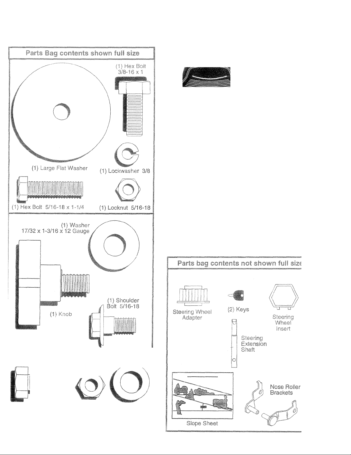
paratelf in carton
Close Roller
\\
(2) Washers 17/32 x 7/8 x 16 Ga,
Manual
Parts Bag
(2) Hex Boils 3/8-16x1 (2) Nylon Locknuts 3/8-16
Page 6
ß-it we I
}T vou
3roper tigfiine
•Ur
^f3.si0r Stanc
rachi
Tire Dressur
.
sn riant or
" - .no v\r
behind the
L't.7
o"" > ■ _ rp." e .0 e ports and Jri1c oarccns
n ul l
I uciiiun
r oe ts fj a yc
• C ut, from top to bottom, along lines on all four corners
of carton, and lay panels flat.
® Check for any additional loose parts or cartons and
remove.
.iJ IS iiieniiui ir >1,1., iif.r 4_j. li
>n the Dor r.a. ■ 'or ted
■■er n.
Uj.
nass0íTib¡0f
mo
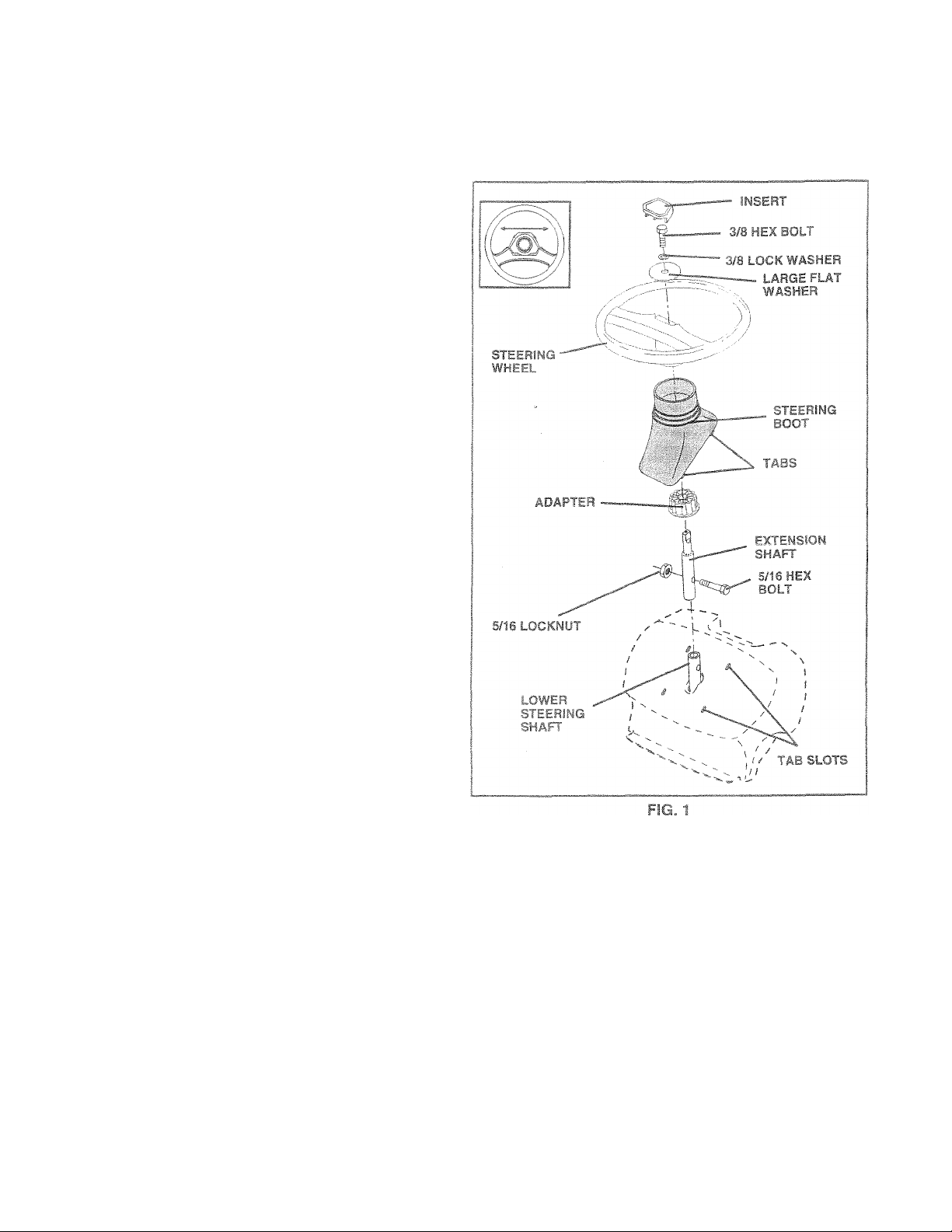
Ü PV ~ SI V/HEEl {Sef* =ec, 1
ASSEMBLE EXT
• Slide extensi
1 ,n . f,T one’ icwer cnatF and
- " h r -( r J’.mr
IM
1 s
DU
j secure.
flNG WHEE
;itfi
• c,ip^ ta~'i wheel nf'f'ifc*=iing t: I r, a;ten
sion.
I whseel;
• - ' ■ - ' , . f _i r' r-- -p a, ' 'j
bars are fiorizoritsl (left to right) and slide onto aeJaptBr.
® MS. am. - _fc 1a Wc iiH, j/8 lO'-i« Washer. 3/B he'
ooi am igri'n se ureC
• Snap steering wheel insert into center of steering
wheel.
® Remove protective plastic materials from tractor hood
and grill.
IMPORTANT: CHECK FOR AND REMOVE ANY STAPLES
IN SKID THAT MAY PUNCTURE TIRES WHERE TRACTOR
iS TO ROLL OFF SKID.
M 'HA.= r AND BC4 7
‘-an at'' ( wer Sibi.r i r naff Aiff n
, C IV^
he
Cl So neve ..untiiiy
in deisn
' ^ -A 7L ', . :t. vH off SKIC tSe€ Gperatiori section for location and function of controls)
* Press lift lever plunger and raise attachment lift leverto
its highest position.
® Release parking brake by depressing clutch/brake
pedal.
* Place freewheel control in freewheeling position to
disengage transmission (See “TO TRANSPORT" in
the Operation section of this manual).
» Roll tractor forward off skid.
* Remove banding holding discharge guard up against
tractor.
Page 7
w
HOW TO Si
uuor.
if this battery is put
n ( It
r ‘ a* > r' "'■''' ~" .
(See "BATTERY" in
suidutio“.' e. r
BATTERY ,
BOX DOOR
TERMiNAL'
¥Ol
№KI
^ TRACTOR
n Bncj open bsttery box
- "i lif r 1 -
' - I' cl .
one hour at 6-10 amps.
-• -£S-'"R£E" IT"
rging instructions).
LABEL
-TERMINAL
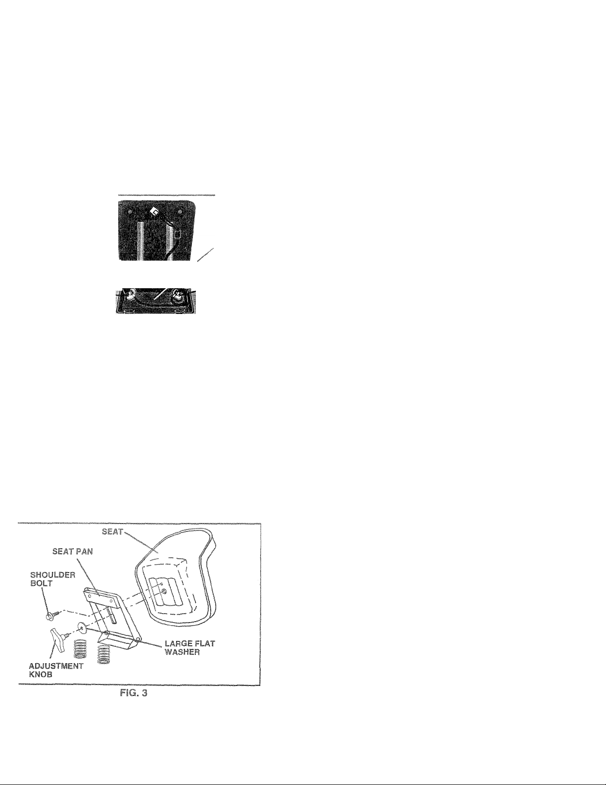
MSTALL SEAT (See Fig. 3)
idjust seat before tightening adjustment bolt.
Remove cardboard packing on seat pan.
Place seat on seat pan and assemble shoulder bolt.
Tighten shoulder bolt securely.
Assemble adjusiment bolt, lock washer and flat washer
loosely. Do not tighten.
Lower seat into operating position and sit on seat.
Slide seat until a comfortabte position is reached which
allows you to press ciutch/brake pedal all the way
do'wn.
Get off seat without moving its adjusted position.
Raise seat and tighten adjurjiment bolt securely.
,/( I
TO
>rac
® Insiail 3/t
MG c .--c .
ne" . i " r r
NO&c
HEX
BOLT
gjr
BRACKET.
TAB
F!G. 4
CHECK TIFT PRESSURE
f s£b" j .-I R V.
sbippirg c..'''~c®'cs Tl m nri*'“
bes. n TT‘rg r.6""‘'.ner. -
® Reduce tire pressure to PBf si*
SPECIFICATIONS" on page 3 o
CHECK DW"
r . f "
iev€
ce: -R ‘ ' I HiM
CHECK “Ch T
8 FLIC
Tea‘he nm r. m ,.w
r'worbGt'" or j tm'i- '
SPi.irw o; f.|S ‘rzfi'- . >/• >r 1 j
CO' -cii I
CHEr-TC“'Ar. " :t-¥
i“c'/'o't''" f )' • » o'‘fa ' ' ,v -t,. ■
.na+ Te ¡..fric r ( ? .u o T !
F^L-rE’ fo .nt Ftrv..„e enc .i' imertr sec .'or or ih
manual.
i O “ Tf
i/ere
? E
nis
Ml
^OWER
1 mot
Adii I
Page 8

ASSEMBLY
^CHECKLIST
ЧАТЕ AND ENJOY YOUR NEW
TO ASSURE THAT YOU RECEIVE
'ANCEANDSATlSFACTiO,
1L
PLEAi
- ^ i - n I 'f(- , . - _ .'1 ■ “
/ 'jc '.a 'e Dec, c
- >-io ' " 0=1- n .
/г j_c iFu „'•'¡arge-. i linimum
1 hour at 6 amps}.
"<-,'■0 ’ -a onhiy istt-Пг-п s^rjiriy.
./ ",!го -i/n>3'=_ ^0'I no.p Г'З Lf'^c'e,
^ 4- Л - ! >0 -¡ra '• !ra I,
fc'O^StCet
^ "30' Cl .^3“ juiiig GO j' “ ( 15. [>"■
.1 ' ‘5’-, г e 'e'lfir’i
' Л ' iG ar.j лае aelîs. be'Ure‘hey ¿re foutec
0 :„c ' a 0!.. c-,c'!a/ ard TSiOf .лИ s elf-eece
j r i r ,-,c £• 9 hai all ocnner-o IS Gfi-sMbecure
c r/v-^ 31 'U^mDed
Z~'< ' - 1,«. •'• ' "*i r. ^ure tme/v^eel rct-Gl is ¡fi
drive position.
V/HILE LEARNING HOWTO USE YOUR TRACTOR, PAY
EXTRA ATTENTION TO THE FOLLOWING IMPORTANT
ITEMS:
/ Engine oil is at proper level.
/ Fuel tank is filled with fresh, dean, regular unleaded
gasoline.
/ Become familiar with all controls - their location and
function. Operate them before you start the engine.
/ Be sure brake system is in safe operating condition.
/ It is importani to purge the transmission before operat
ing your tractor for the first time. Follow proper starting
and transmission purging instructions (See “TO START
ENGINE” and “PURGE TRANSMISSION” in the Op
eration section of this manual).
8
Page 9

.-iPeeaTíO?'^
These symbols may appear on your tractor or in literature supplied with the product. Learn and understand their meaning.
I
♦
BATTERY
©
ENGINE ON
i
FUEL
CAUTION OR
WARNING
pv» -or-'
p' • vrj
to
ENGINE OFF
l\l
CHOKE
R
REVERSE FORWARD FAST
"fir
OIL PRESSURE
MOWER HEIGHT
N
LIGHTS ON OVER TEMP
to
PARKING BRAKE
LOCKED
H L
-t'ri
LIGHT
UNLOCKED
SLOW
f
if
MOWER LIFT
ATTACHMENT
JJTCH ENGAGED
IGNITION
DANGER, KEEP HANDS AND FEET AWAY
REVERSE
ATTACHMENT
CLUTCH DISENGAGED
NEUTRAL
HIGH LOW
KEEP AREA CLEAR SLOPE HAZARDS
(SEE SAFETY RULES SECTION)
PARKING BRAKE
FREEWHEEL
(Automatic Models only)
Page 10
OPF RATION
^*11'P jc.t- r» m
- £1 r ^ AMPS--;“'■f PriF'.l-i^'r.REOPfr’^-Wf.'^OUP :riR
Compare the
this manual 1
I I i With < .. ¡1- , f io familial
iture reference.
•urseif«/iihthe> - n.iisofvarioM- '-andadjustments. Save
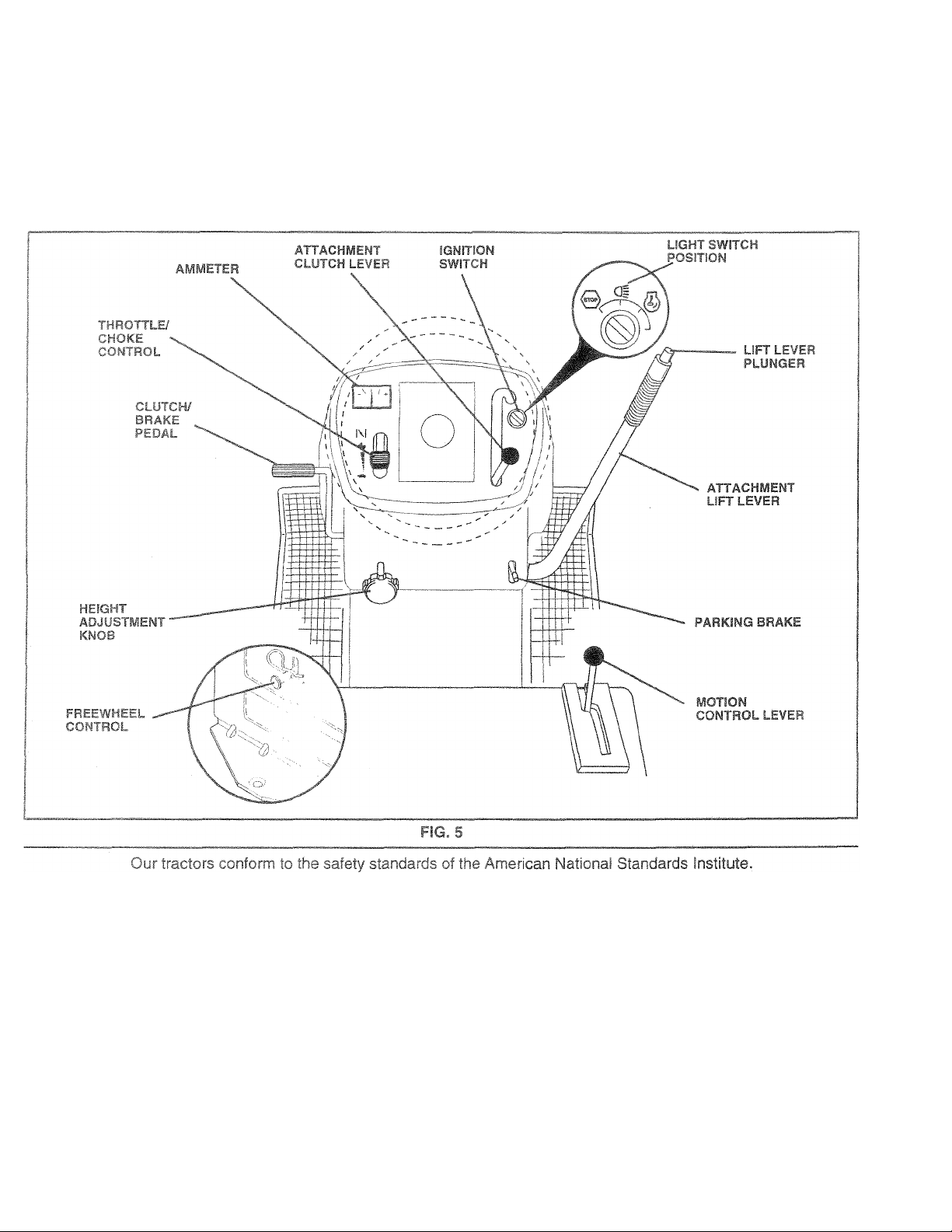
ATTACHMENT CLUTCH LE¥ER: Used to engage the
mower blades, or other attachments mounted to your
tractor.
LIGHT SWITCH: Turns the headlights on and off.
THROTTLE CONTROL: Used to control engine speed.
CLUTCH/BRAKE PEDAL: Used for declutching and brak
ing the tractor and starting the engine.
PARKING BRAKE: Locks dutch/brake pedal into the
brake position,
MOTION CONTROL LE¥ER: Selects the speed and
direction of tractor.
FREEWHEEL CONTROL: Disengages transmission for
pushng or towing the tractor with the engine off.
ATTACHMENT LIFT LEVER: Used to raise and lower the
mower deck or other attachments mounted to your tractor.
LiFT LEVER PLUNGER: Used to release attachment lift
lever when changing its position.
IGNITION SWITCH: Used for starting and stopping the
engine.
HEIGHT ADJUSTMENT KNOB: Used to adjustthe mower
height.
AMMETER: Indicates charging (+) or discharging {-) of
battery.
10
Page 11
Ciâîî1â00,* ÂlWâyS W©âf Sâf©ty §ll
- •î*-'-"rrc ,il r*.-''«"' ' '},
HC ’H* ^ " " L - î- - 'Í73P.
T SE “ — - ?.i: ” ? ^ 5 ¿C'f = g. ■
Depress
and hole
release pressure ire
r^Dsasr s / ^ S D i ^'1" /i; „ iV SSfO
Will hold tractor secure.
da! into full “BRAKE” position
'0 iH = u-'“5 Pads'ct ', "
NO I h; under i
idle with theenq
rr-U*”" C'' •.
pletelf, as described
A
grass catcher, etc.
TO USE THROTTLE CONTROL
Pi<‘i ' _- r • *
battery charging rate.
® Full throttle ofv
• >Pr. ‘ -
lers 1 lower perro
TO MOVE FORWARD AND BACKWARD
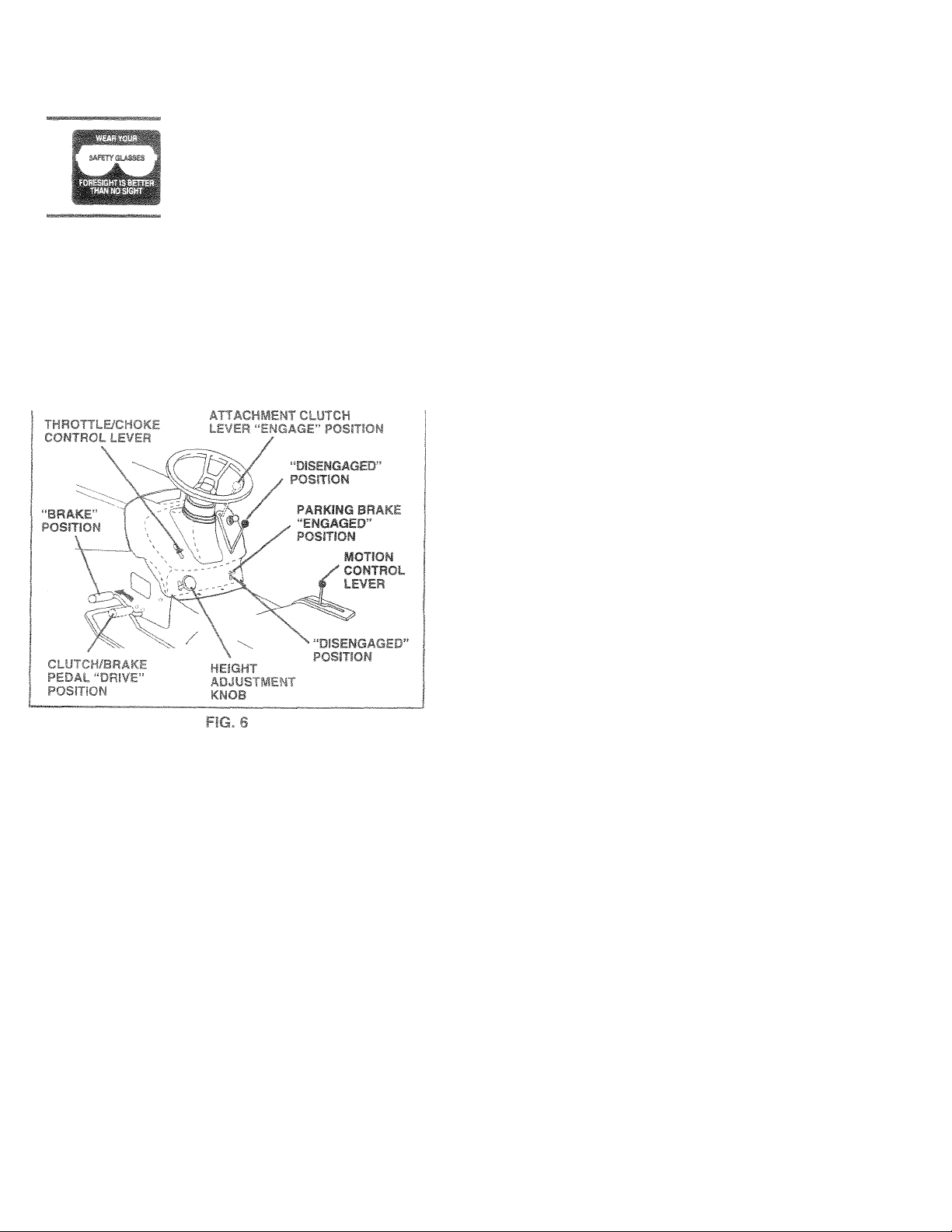
(See Fig. 6}
The direction and speed of moyement is controlled by the
motion control lever.
® £ . < i t t ra o K' i w ih ( o
prciiirn.
® ¡.ark,n._
SIcwlv rrin
miroi lever in neutral
iicn/DraKe pedal,
re! to desired positii
STOPPIN* g. 6)
MOWER BLADES -
® To stop mower blades,move attachment cluicfi leverto
“DISENGAGED” position.
GROUND DRIVE -
» To stop ground drive, depress ciutch/brake pedal into
full “BRAKE” position.
® Move motion control lever to neut.raf (N) position.
iMPORTANT: THE MOTiON CONTROL LEVER DOES
NOT RETURN TO NEUTRAL (Ni POSITION WHEN THE
CLUTCH/BRAKE PEDAL IS DEPRESSED.
ENGINE-
* Move throttle control to slow position.
NOTE: Failure to move throttle control to slow position and
allowing engine to idle before stopping may cause engine
to “backfire”.
• Turn ignition key to “OFF” position and remove key.
Always remove key when leaving tractor to prevent
unauthorized use.
® Never use choke to stop engine.
IMPORTANT: LEAVING THE IGNITION SWITCH IN ANY
POSITION OTHER THAN "OFF" WILL CAUSE THE
BATTERY TO BE DISCHARGED, (DEAD).
imum
The cutting heigh
so U . , .
® Turn knob cloc
rf=igni.~ r • - y
the -rgne ‘i". .m r_ - *
and T!c vcT uevs'J. L . j >r , (-jO
grass dOJ t.-pfs
® ’ he 'awr -r" „.sc oe' , mr p t * c-m _
inches during the cool season and to over 3 inci
"•unre he m'">ih c:,-r rc-^it-icr't, ; ■
lawns mo/ s.te'^ ard rrs -ro.j~h.
■* i^'-f oe=' r sting per orr anc <:v.;r t~ .>ic '»*heiont c'’cl'o'^€ TIG''od twice r'
re'ativi^.', r 'On he se r> d Cc. • n- cm
11
id to th
-1 i =
annroxirr
her
”S
5
» in
cut
Page 12
OPERATlOí
1
IPD It
MOW
' < • I ! h , ' ' > i i' t 0>‘-^. ~i l I <1,
switch. Any atternpt by th© operator to leave the seat with
i ll . ' ■ ■ O' . I l f ) I - i W l • ■ I C ' .J i ' ' rj 'i
^ _s,- rc v='/i.th artsc'."¡e 0 .ifT, .nti-''!
* hi-’ c / = c aOes 0/ e loarny ariPfin-e^i -
-cr« s
, ' C Ç r _ - y' .py puga: „ joytafu f. : .
jiC'
wAuTtOfl. Do r»oc jperaie he nower |
w't^out aithei the entire grass caichei* I
A
cn rtiowers S3 equioped cr the dls- s
charge guarc in place, 1
If
U ' ‘ Ji . iy I I I V' l i ' J
!■' 'i i r ' V r| i ,, , fi, i . /•“V -<
position. Free wheel control is
•in«s
ol lU O
c. - c'om/.t. j!
of tractor.
' - -“r
merit iift control.
H,' 'c= vL-e' . 'I * r ro ->id i :iL‘i, L/
.'-."‘rig >eEar-rsowiC .i: fc'-v-i'c noto :> sc" red.
® ^ ■ ■.3.z,z~ - ms 5 fdr .c'C.iVH.
• ' r ^ ‘rs . i'.''-aL'' - cr'os'rom*.
TCTc "v O'^oa iCiTi damagfe wi.fc''’"ansDorripp
ycurractor a ruck"'» a '•'a.le- oe sure hood ;s closed ana
jC..,..red'c tmc.‘ r UAear.apprcpr.atciriBar'o .^fry,r,g““ci^u
m trac.o .repe, d eic ■
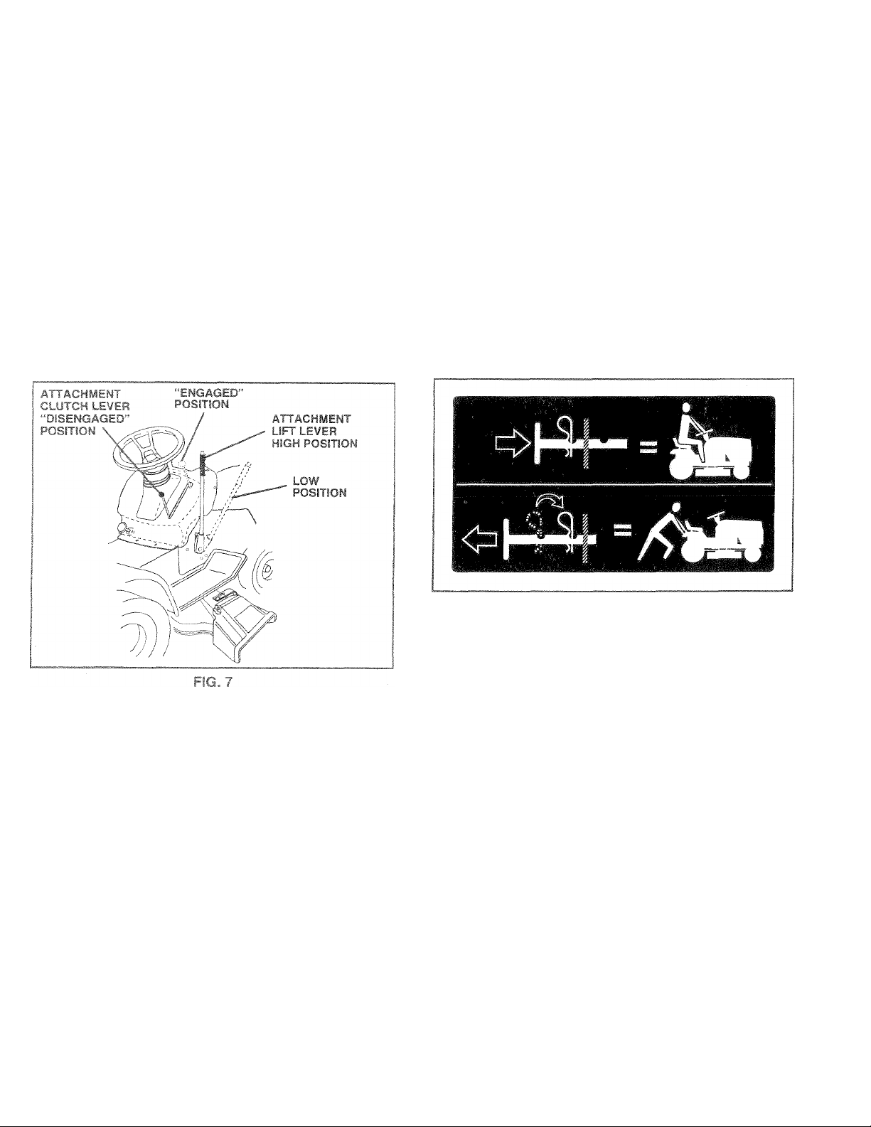
TO OPE-'A" r Dhl HILLS
C-AÜT'C”: Gcncî drr^eupordowRÍisíío
With î'cpes greater than 15° and do net
A
» Choose the slowest speed before starting up or down
hills.
® Avoid stopping or changing speed on hills.
* If slowing is necessary, move throttle control lever to
slower position.
• if stopping is absolutely necessary, push clutch/brake
pedal quickly to brake position and engage parking
brake.
» Move motion control lever to neutral (N) position.
IMPORTANT; THE MOTION CONTROL LEVER DOES
NOT RETURN TO NEUTRAL (N) POSITION WHEN THE
CLUTCH/BRAKE PEDAL IS DEPRESSED.
® To restart movement, slowly release parking brake and
clutch/brake pedal.
® Slowly move motion control lever to slowest setting.
® Make ail turns slowly.
hr*ve across any sfooe.
FiG. 8
BEFORE STARTiNG THE ENGINE
CHECK EUGME OIL LE¥Ei_ (See Fig. 13)
* T he engine in your tractor has been shipped, from the
factcn/ralready tilled with summer weight oil.
® Check engine oH with tractor on level ground.
* Remove oil fii' cap/dipstsck and v/ipe clean, reinsert the
cicstiCK and screw cap tight, wait for a few seconds,
temere OiC read oii ievek if necessary, add oil until
‘■RuLl’ inarK on dipsticK is reached. Do not overfill,
® h sr sci-J weather operation you should change oil for
easie,'- starting 'See “OIL VISCOSITY CHART” in the
Cusiorner Responsibilities section of this manual).
* To change engine oil, see the Customer Responsibili
ties section in this manual.
ADD GASOLINE
» Fill fuel tank. Use fresh, clean, regular unleaded
gasoline with a minimum of 87 octane. (Use of leaded
gasoline will increase carbon and lead oxide deposits
and reduce valve life). Do not mix oil with gasoline.
Purchase fuel in quantities that can be used within 30
days to assure fuel freshness.
iMPORTANT: WHEN OPERATING IN TEMPERATURES
BELOW 32°F(0'’C), USE FRESH, CLEAN WINTER GRADE
GASOLINE TO HELP INSURE GOOD COLD WEATHER
STARTING.
12
Page 13

np pnrf fpf
Ci,
-r
fuel
bier
^age. To avoid engine
be erriDtied before stor-
uld Í
■'ain
J0f li " ~c i <„arcu. s.c " a
asor1. See Storage Instruc-
)n.
Never use engine or
-'-A t ” r-nt
® Allow one minute for transmission to warm up. This
can be done during the engine warm up period.
The attachments can also be used during the engine
warm-up period after the tran.smission has been waimea
up.
MOTHi If 3Í E hiyli sitituds (sbovs 30^
JO fG0[i C
h ilJ6( fTilX
.S 9 £10SfC'0 " 00
JSIITI
ssGiion Of lilis msnusí.
PORGI
T°0 MOI
3 3.nd AdH
¿r* f
WAtJ
filler
ed oil or
A
IME
w i r- w~ I i 2' = A M r ' -O' me
ue!
neg
see r-i
5cr*c t; ci ¿Jz. .yfl
ir iftp's :rra'
~'C^ AO'B. spif’
. I ! " 'M 'K^c AK Tc " t /e
fuel from the
be sure
aaaed oc
-driK
see! com
)n
'
s in the transmission en-
’ tt< tr -1!, mc'cji t - i.iCi aepress clutch/Diake
ptjai C..-.U set park..ng'c,c;ke.
• Place motion control lever in neutral (N) position.
® yove attachment dutch to “DISENGAGED” position.
•• Move throttle control to choke position.
NOTE: Before starting, read the warm and cold starting
procedures below.
» Insert key into ignition and turn key ctockv/ise to “START"
position and release key as soon as engine starts. Do
not run starter coniinuously for .more than fifteen sec
onds per minute. If the engine does not start after
several attempts, move throttle control to fast position,
wait a few minutes and try again, if engine still does not
start, move the throttle control back to the choke
position and retry.
WARM WEATHER STARTING (50° F and above)
• When engine starts, move the throttle control to the fast
position.
® The attachments and ground drive can now be used. If
the engine does not accept the load, restart the engine
and allow it to warm up for one minute using the choke
as described above.
COLD WEATHER STARTING ( 50° F and below)
• When engine starts, allow engine to run with the throttle
controi in the choke position until the engine runs
roughly, then move throttle control to fast position. This
may require an engine warm-up period from several
seconds !o several minutes, depending on the tem
perature.
AUTOMATIC TRANSMISSION WARM UP
® Before driving the unit in cold weather, the transmis
sion should be warmed up as follows;
® Be sure the tractor is on level ground.
® Place the motion control lever in neutral.
Release the parking brake and lei the ciutch/brake
slowly return to operating position.
Ti, r
nino.
10 ensure proper«
T b'lupo '(¡a To '
tractor for the first time. This proc 6GUr€
1 , C,r - ‘>-r
■ mr:*’ Mm.I J ' " i "
i.uiPOF’^rt m ^ >
lission De pi.
r
---------
i
•-
3 Will rGrnove a
Ì
ÍÜW
WhlCr
ISSION REOUT
.NSMi
REMOVAL FOR SERVICE OR
SHOULD BE PURGED .AFTEF
= E- 'P-E E-F IV 1 E -/ U
® F ace , £,'< / q-. tov«i
pc
fc '
a* fr t
® Disengage transmission by pic
in freewheelinq position (See
I ! '
Sittinq in thi
INSTALLATSC
TOR.
face V
!/iih engine otfai
freewhesi conti
icing
ííT‘f\
'
TRANSPORT”
ir i
.( '■•■'p- • n
3n c
ai (N) position, sic
» ■,
»dure thre^
NOTE: During this procedure there will be no movement of
drive wheels. The air is being removed from hydraulic drive
system.
® Move motion control leverio neutral (N) position. Shut
off engine and set parking brake.
» Engage transmission by placing freewheel control in
driving position (See “TO TRANSPORT” in this section
of manual).
® Sitting in the tractor seat, start engine. After the engine
is running, move throttle control to half (1/2) speed.
With motion control lever in neutral (N) position, slowly
disengage ciutch/brake pedal.
® Slowly move motion control lever forward, after the
tractor moves approximately five (5) feet, slowly move
motion control lever to reverse position. After the
tractor moves approximately five (5) feet return the
motion control levertothe neutral (N) position. Repeat
this procedure with the motion control lever three (3)
times.
® Your tractor is now purged and now ready for normal
operation.
13
have dov'
Page 14
MOWI
• Tire chains cannot be used when the mower housing
is attached to tractor.
® Mower should be properly leveled for best mowing
performance. See “TO LEVEL MOWER HOUSING” in
the Sendee and Adjustments section of this manual.
• The left hand side of mower should be used for trim
ming.
• Drive so that clippings are discharged onto the area
that has beer*, cut. Have the cut area to the right of the
machine. This will result in a more even disiribuiion of
clippings and more uniform cutting.
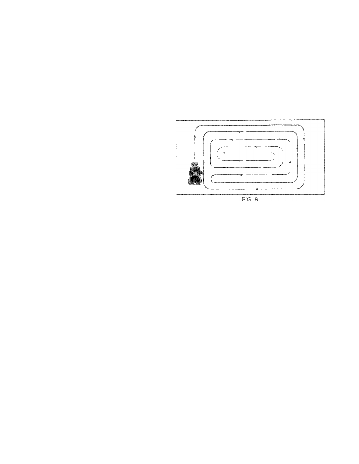
• When mowing large areas, start by turning to the right
so that clippings will discharge away from shrubs,
fences, driveways, etc. After one or two rounds, mow
in the opposite direction iTiaking left hand turns until
finished (See Fig. 9).
» if grass is extremely tail, it should be mowed twice to
reduce load and possible fire hazard from dried clip
pings. Make first cut relatively high; the second to the
desired height.
)le clurrtc
wng.
} engine at
TlOWinO p€
w,- m f I ,< Hc'it'jte gr :i i c-ce- •'
. ly . '.n.,ug, yta* m c'% j.t m v-r"
tnroitfe when mowing to
> -mvr -7 . _ t..' Jc
re-,, -aif y as h- 1. £:■' , c m -c-.-*
Dfci c ^ -p—-
mm , he a, d i e '-i" '-i. . .n < a
14
Page 15
Iv I %»#IWitri nt Vi VIÖ11—I I lt-'*J
3IVIP
I W
I i/
■v^
__L
ir
I
'^6
^ - J
_____
r
I
-J-.
V^Ci'-^.O irr-
GENERÄL
T H
D— '• S i
DilMI
yriÄ"
LI#4
i not C0\
r Items tnai i
3"!i
receive ful! value from the warn
tractor as instructed in this rng
Sc ,k dd|is rci- vm •. v--
jai.
Is -nao“ penodi uiiw hi
properly maintain your iracior,
Ai! adjustments in the Service and Adjuirtments seciion of
this manual should be checked at least once each season.
* Once a year you should replace the spark plug, clean
or replace air filter, and check blades and belts for
wear. A new spark plug and clean air filter assure
proper air-fuel mixture and help your engine run better
and last longer.
BEFORE EACH A'LE
* Check engine oil levei.
® Check brake operation.
> Check tire pressure.
• Check operator presence and interlock systems for
proper operation.
• Check for loose fasteners.
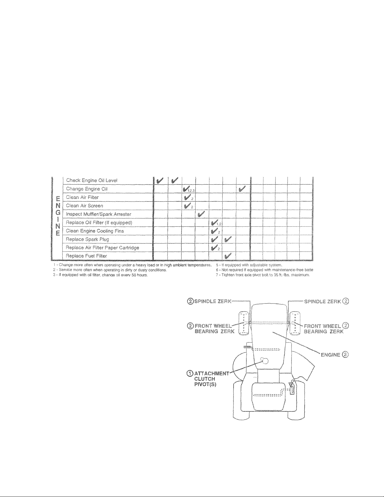
LUBRICATION CHART
CDSAE 30 OR 10W30 MOTOR OIL
©GENERAL PURPOSE GREASE
©REFER TO CUSTOMER RESPONSiBILITiES “ENGINE” SECTION
MPORTANT; DO NOT OIL OR GREASE THE PIVOT POINTS
WHICH HAVE SPECIAL NYLON BEARINGS. VISCOUS LUBRI
CANTS WILL ATTRACT DUST AND DIRT THAT WILL SHORTEN
THE LIFE OF THE SELF-LUBRICATING BEARINGS. IF YOU
FEEL THEY MUST BE LUBRICATED, USE ONLY A DRY, POW
DERED GRAPHITE TYPE LUBRICANT SPARLNGLY,
1.^
Page 16

, PESí^OMS!B!línE=
TE
OH
nainte-
BRAKE OPI
. ir
at high speed ir
(See “TO ADJ
n it fib seciK 1
- .
hest gear,
; [■ /1 * h
Jai
1 ec t'p) 1 j I. j .-
:> Tr^e TitsTce aojusTsc.
ir. h-_ ^iip anc -^djLsi-
TIRES
® ivlaintain proper air pressure in all tires (See “PROD
UCT SPtCIFICATIONS” section of this manual).
• Keep tires free of gasoline, oil, or insect control chemi
cals which can harm rubber.
® Avoid stumps, stones, deep ruts, sharp objects and
other hazards that may cause tire damage.
NOTE: To seal tire punctures and prevent flat tires due to
slow leaks, tire sealant may be purchased from your local
parts dealer. Tire sealant also prevents tire dry rot and
corrosion.
OPERATOR PRESENCE SYSTEM
Be sure operator presence and interlock systems are
working properly, if your tractor does not function as
described, repair the problem immediately.
• The engine should not start unless the clutch/brake
pedal is fully depressed and attachement clutch control
is in the disengaged position.
• When the engine is running, any attempt by the opera
tor to leave the seat without first setting the parking
brake should shut off the engine.
• When the engine is running and the attachment clutch
is engaged, any attempt by the operator to leave the
seat should shut off the engine.
® The attachmentclutch should neveroperate unless the
operator is in the seat.
¡AILING
MANDREL
ASSEMBLY
t
FLAT tf isHF.'-i
LOCK AfA-Sdfc'
HEX BOLT (GRADE 8)*
*k GRADE 8 HEAT TREATED BOLT CAN BE
IDENTIFIED BY SIX LINES ON THE BOLT HEAD.
FIG. 10
TO SHARPEN BLADE (See Fig. 11)
NOTE: We do not recommend sharpening blade - but if you
do, be sure the blade is balanced.
Care should be taken to keep the blade balanced. An
unbalanced blade will cause excessive vibration and even
tual damage to mower and engine.
• The blade can be sharpened with a file or on a grinding
wheel. Do not attempt to sharpen while on the mower.
• To check blade balance, you will need a 5/8" diameter
steel bolt, pin, or a cone balancer. (When using a cone
baiancer, follow the instructions supplied with bal
ancer.)
NOTE: Do not use a nail for balancing blade. The lobes of
the center hole may appear to be centered, but are not.
» Slide blade on to an unthreaded portion of the steel bolt
or pin and hold the bolt or pin parallel with the ground.
If blade is balanced, it should remain in a horizontal
position. If either end of the blade moves downward,
sharpen the heavy end until the blade is balanced.
B.w‘:cwRE
For best results mower blades must be kept sharp. Re
place bent or damaged blades.
BLADE REMOVAL (See Fig. 10)
» Raise mower to highest position to allow access to
blades.
• Remove hex bolt, lock washer and flat washer securing
blade.
» Install new or resharpened blade with trailing edge up
towards deck as shown.
IMPORTANT: TO ENSURE PROPER ASSEMBLY,
CENTER HOLE IN BLADE MUST ALIGN WITH STAR ON
MANDREL ASSEMBLY.
• Reassemble hex bolt, lock washer and flat washer in
exact order as shown.
» Tighten bolt securely (27-35 Ft. Lbs. torque).
IMPORTANT: BLADE BOLT IS GRADE 8 HEATTREATED.
16
Page 17

BATTERY
Your tractor he
cisnt for norm.
battery with ar
® Keen bat'^c
IS a batteiy charging system which is suffial use. However, periodic charging of the
I automotive charosr will extend its life.
ip/ and terminals dean.
® K.eep Dattc
30
II vsnt liolss op@n.
® HBcharge at 6-10 amperes for 1 hour.
I I'D 1 ’ 1 _
maintenance fi
or covers. Adc
; 1 = 1 1. tU' ic. ‘ .1 -• V m- , ;
-r-y r ^ z.’itr!i‘ > e;i' ' rr .
’ ' > ' 1 , - - ' _ . ot
n L
iTTERY AND TERMINALS
Corrosion and dirt on the battery and terminals can cause
the battery to “teak” Dower.
)nriec
r r' - Cl- r I - ^with plsi
0
' 'e-nc-rT .
r,, '' cm
9
&
- -'nGt. ‘ Lai f.. /
SERVICE .AND
msnuai).
t>7 J' '>ei í r oaí-
;re' í n ‘a j .
A, ‘ ^r,
nd baiter
th nrpBSi
^ r-p toíY
ADJUS
/ :br <= -I d' .ííif wire brush
r-^; d-^.Y" iníhe
>.u>CY~ sef-tnr* oí this
1
---
^—
Lf ^ V
1 op 3QO
NOTE:
improvi
»V ■. r-
jr enqin
p - r 1
CbSflQC
ones 3 ^
Cr
arc a -i if_
cap/""; c 1., 1 ^ ^ -
TO CHANGE ENGINE OIL (See
CeV- £ ir.e e, 'e a.i ,e c, - j.
A,l o‘i 'll n' -■ '
® Be sure tractor is on level suf
> Cl! fjll r r 6 /< I'5
® fei ^ ' t
* Remove oil fill cap/OipsticK. B
to enter the engine when cha
Chfí/< V-bei'í*c.
operation and ref
aojj": cr-ltí. ^ -D’t'
r» ^ /. I £. . 5,j,
The transmissior
“a '/earaiter OOhüutsof
oelís not
r _i 3iiD'rom wear.
■Id be Kepi dean
K' . ir- '
Df >•’1 'I - I . I-' - [ i:.: n r mr r>
lU 1 . .C <•' i' U ‘ . ' M>£ • t h( , T- ¡ even f L
sitie damatjO :o seáis, de not uct. bagt! pressure water ur
steam to clean transaxle.
• Inspect cooling fan to be sure fan biades are intact and
clean.
» Inspect cooling fins for dirt, grass clippings and other
materials. To prevent damage to seals, do not use
compressed air or high pressure sprayer to clean
cooling fins.
TRANSAXLE PUMP FLUID
The transaxie was seated at the factory and fluid mainte
nance is not required forthe iife of the transaxie. Should the
transaxie ever leak or require servicing, contact your near
est authorized sen/ice center/department.
ENGINE
® Aftsr 01! fiHS drainocl compiotr
-ir ■<,<,•/ r -
“PRODUCT SPECiFiCATION
» Use gauge on oil fill cap/dipsti;
reading. Keep oa at
LUBRICATION
Only use high quality detergent oi! rated with API service
classification SF, SG, or SH. Select the oil’s SAE viscosity
grade according to your expected operating temperature.
Page 18

CJJSTOWEP PESPONSiBJLmES
a. 141
j ( IH
in the foam
^leaner after
no
Hemov6
^ .0 • over
— ^I-
■’ : oeirfef A, ”000:'=-
, j V j-o vat-
'■ ' r r. 5 ‘i-,1 coth
• ^ 1 ~ >jìf.- .1 ri >t. t r, a-n I" r 1
m Lo-zc ' c
si ^ ^ J -J t 1 (. a WS i 1 1^ ^5 j ^ I I ( C" 4^ i i i »
>» -• ■ ’'-i ,v " ■ c 6, ..anooga.
® Reinstall cover and secure with knob(s).
TO SERVICE CARTRIDGE
• Remove cartridge nut.
• Carefully remove cartridge to prevent debris from en
tering carburetor. Clean base carefully to prevent
debris from entering carburetor.
• Cleancariridgebytappinggentlyonflatsurface. Ifveny
dirty or damaged, replace cartridge.
• Reinstall cartridge, nut, precleaner, cover and secure
with knob(s).
IMPORTANT: PETROLEUM SOLVENTS, SUCH AS
KEROSENE, ARE NOT TO BE USED TO CLEAN THE
CARTRIDGE. THEY MAY CAUSE DETERIORATION OF
THE CARTRIDGE. DO NOT OIL CARTRIDGE. DO NOT
USE PRESSURIZED AIR TO CLEAN OR DRY
a a dirty air filter.
i5 hours of operairtridge every 100
Tever occurs first.
CLEAN REEN iSee Fìq. 15
V ^ L f
Air scr
engine
or com
;e keot
move
, ' I < ■ VI .< ^ ,
r 4- -.1 mitt j , I. hi 1, *
r
<i'V
I 'III- ' I
'.I
ENG7-JE =:NS .See rfg ’5.
Rpnlr^^ -n./ V|, 4 -jl, Q -^1 ,Vo~ -ng.-c -Z' l,r|f un io
pro entonyirb lamags imRi jié rsahiiu
* re y= imrr’ hjnvver noi'F-pg arri D •'nti .h„
arpo c’lps'mfr Jbe issemDK idengir»
» ( - r 0 ' I'i -pe'ii' j '0 c'-^vert eoir^ ZfZil
- St, ccnar=^eed a.i'or 3iT Lrib'le trus*^ *c
■’Tan =i^g>pe "''riing ¡¡ns
® 'c 1-c‘^sentic e’<erce above crocs "ure
FiG. 14
FIG. 15
18
Page 19

CUSTOMER RESPONSIBamES
repic
ijippeaj
H Anl£?r-i
jeasori -r PTier >T ! gl»-' ofaftrat.cn «niche^/t'
"Fr'CCPt " src. - 'e'.C >S sec'ijr jf*h's .""a. ual.
s itc
5Uld crc
.115pct>-k Giup '\pe a.'d yao selling are snow" .n
n r ,,•) I
h, >i . r./
rresteriif
'in
IN-LINE FUEL FILTER (See Fig. 16)
The fuel filter should be replaced once each season. If fuel
filter becomes clogged, obstructing fuel flow to carburetor,
replacement is required.
* With engine cool, remove filter and plug fuel tine
sections.
» Place new fuel filter in position in fuel line with arrow
pointing towards carburetor.
» Be sure there are no fuel line leaks and clamps are
properly positioned.
* Immediately wipe up any spilled gasoline.
CLEANING
® Clean engine, battery, seat, finish, etc. of all foreign
matter.
• Keep finished surfaces and wheels free of all gasoline,
oil, etc.
• Protect painted surfaces with automotive type wax.
We do not recommend using a garden hose to dean your
tractor unless the electrical system, muffler, air filter and
carburetor are covered to keep water out. Water in engifie
can result in a shortened engine life.
19
Page 20

SERVICE AMO ADJUSTMENTS
CAUTION: BEFORE PEaFORMING ANY SERVICE OR ADJUSTMENTS:
Depress clutch/brake pedal fully and set parking brake.
Place motion control lever in neutral (N) position.
A
“Ea'.c- tc. I MEf SfecT rig. !
iv,z \ - A !-'TiD'-i- ,-t •"!-Hhc't iav_r
' -'a^5 r, ‘_/IFch-GAAFr J.OS- '~n
"< vr li't e/.f' /'-rrf' c'//errro'ver‘o is
• Roll belt off engine pulley.
• Disconnect clutch rod from clutch lever by removing
retainer spring.
® Disconnect anti-sway bar from chassis bracket by
removing retainer spring.
• Disconnect suspension arms from rear deck brackets
by removing retainer springs.
•• Disconnect front links from deck by removing retainer
springs.
• Raise lift lever to raise suspension arms. Slide mower
out from under tractor.
IMPORTANT: IF AN ATTACHMENT OTHER THAN THE
MOWER iS TO BE MOUNTED TO THE TRACTOR,
REMOVE THE FRONT LINKS.
Place attachment clutch in “DISENGAGED” position.
Turn ignition key “OFF” and remove key.
Make sure the blades and all moving parts have completely stopped.
Disconnect spark plug wire from spark plug and place wire where it cannot come in contact with
plug.
tier
TO PSTALL MOWER (See Fig. 17)
® Raise attachment lift lever to its highest position.
» Slide mower under tractor with discharge guard to right
side of tractor.
® Lower lift lever to its lowest position.
• install mower in reverse order of removal instructions.
20
Page 21

àun 40 - -
HOUSING
level QrOUnQ О
5УГЕ
3W€
Ba „e 'r 1 ii 'га
'MtlU .
^ -nf_ -- rip3 xnz^-fz , Г'.~ heio'-t
ticr 1‘ *"'>■ - * je-/ T c'ver''*'L'i.=*anc-“A" л
tfihr c«- L~ I ► ' fTi". rwiif.in
0 -^ac,
’ i, _GI ^ ,n
C|r^ T r't a
e T: - f' 'Г - :
I ь .e - jufirneni on one
irite
nU 01. OC
^ T
nut on that Sid
^■}ГЕ Тоаъ
I -.01 i ^ er nut wili change
¡Ti.v/ci hpioh, “ГО
cf h-.~’ m6&E_rei'r=-ntc arte' aGiiist>rc,
■ inflsied (Sei
of this гт1зпий1)
properly adjus
■: 3 and S Э)
' ■* usimem
adjustment
IE Fi
To obtain the best cutiing
ll 'oh-- ^ I i,"
—,
ы'~
po'^'fcr
Che:r чС’о . n oi i
kr. - ‘ 1 ‘I-' if r
edc- (rt r ъ II I! •
‘ Гг^о •J.r'o'' f'c
=004. , r, -t-. |f •/ -
^ V 5 P " О -i
ijust one link to ?
i Ì i^-'i i<
•zii'-' ’ ' 4c . lì -ui "E” - 'Л
links an equal number of turns.
■'v'f'si ■'fsT' ' m t ■/_" ' \ (
i=ai 10.' >‘z.i m ’ i n 1 .1 .
1 i n k" »di'
I’- Гш-с lOii :i O'j’vfc' icra.<in. i,' . m
^ Ри''” Гt СГ '■ г- 'Г
ecuai пипсе ; iLrn..-.
Wnen cis.arn ‘3 /S‘ > ' i .hor..
reoqiigriie. л„. . ronaoiol
Recbeck'ПО Ч rc г m -pt.
FiG. 19
S \ JZ
/Л
I cm
0O
til
i Veai^
ч-
MANDREL
NUT "E"
Page 22

SFF.vif f mD an.insTf-.iFfjT'^
lOWER BLADE DRIVE BELT
(See Fig. 22)
The mower blade drive belt may be replaced without tools.
Park the tractor on level surface. Engage parking brake.
BELT REMOV.AL -
® Remove mower from tractor (See “TO REMOVE
MOWER” in this section of this manual).
® Work belt off both mandrel pulleys and idler pulleys.
• Pul! belt away from mower.
BELT INSTALLATION ^
® instal! new belt in reverse order of removal.
* Make sure belt is in all pulley grooves and inside all belt
guides.
® install mower in reverse order of removal instructions.
PANDREL
PULLEY
\,
IDLER
PULLEYS
4
PULLEY
FIG, 22
WITH PARKING BRAKE “ENGAGED”
NUT“A”
JAM NUT
L u »JW- r-*IS -YJ . ;r
S,lEhl :s .YECESSAR/
.'-'iR »EASES’" ibiMOPilD
~=o/DE=A'= 'mu.r
FiG. 23
1 T ^EFLTCc DRIVE BELT
(VFG ~SG- 2A,
F^ir\ Ilf itac l; . i rfEngage parking brake.
F^r atsirtan:: ,r.c e y r dry .nstailation guide decai on
0( non tn- Mr . cat
- Rerrm - mo REMOVE MOWER” in this
sertic" ' ni' 'a. loa*'
Fe.mr =- celt jorr siat'Ciwr / idler and clutching idler.
‘ I I jI&i" ! ‘'■'JQ ■‘-ci. I tractor. Carefully remove
UflM CY i"srf‘’'' imrsm s'rion input pulley and over
' ■! no ,n ,..cl C
)r and remove downward
lie c ' Ui I I 1.
above procedure.
Your
whicf
with ar
iide of the transaxte.
If trac
a t I
De.ve ‘■m
Measure distc
nut “a”
THnCfe Ufc
' on bra-^e rod
It, "< 5, e idjusted.
- a ^eccrking brake.
4aei CO jperating arm and
If distance is other than 1-9/16", loosen jam nut and
turn nut “A” until distance becomes 1-9/16“. Reiighten
jam nut against nut “A”.
Road test tractor for proper stopping distance as stated
above. Readjust if necessary. If stopping distance is
still greater than six (6) feet in highest gear, further
maintenance is necessary. Contact your nearest au
thorized service center/depariment.
I system
distance
22
Page 23

-Iflì. -
TRANSAXLE MOTION CONTROL LE¥ER
i JSTMENT (See Fig. 25)
The motion control lever has been preset at the factory and
adjustment should not be necessary.
• Loosen adjustment bolt in front of the right rear wheel,
and lightly tighten.
® Start engine and move motion control lever until tractor
does not move forward or backward.
* Hoid motion control lever in that position and turn
engine off.
•» While holding motion control lever in place, loosen the
adjustment bolt.
Move motion control lever to the neutral (N) (lock gate)
position.
NOTE; If
ment bolt,
liter above adjustment is made,
U. C i _ _C i * - i V . t r -' l i r
osition, follow these steps:
Loosen the adjustment boil.
Mr ve . - r,i . '' , , - j ,
(j! <r r I t O/ re ^ ' "rc-
' I.,it- I f .r i~ '( '
V O h
i l i ’' a ct O ’' ‘ “ f ec t , C' 3
:VEF
1»
id to get to adj usi
le lowest position.
b . ..imr , seo«
1/2 inc
/5 Ul !ilf bet
I „for
dA i r
TO REMOVE WHEEL FOR REPAIRS
(See Fig. 2S)
» Block up axle securely.
* Remove axle cover, retaining ring and washers to allow
wheel removal (rear wheel contains a square key - Do
not lose).
« Repair tire and reassemble,
® On rear wheels only: align grooves in rear wheel hub
and axie. Insert square key.
s Repiace washers and snap retaining ring securely in
axle groove.
* Replace axle cover.
NOTE: To seal tire punctures and prevent flat tires due to
.slow leaks, tire sealant may be purchased from your local
parts dealer. Tire sealant also prevents tire dry roi and
corrosion.
WASHERS
RETAINING
aiNG
AXLE COVER
TO HTTP
5^*^ "j -
SQUARE KEY
(REAR WHEEL ONLY)
IF
'm
■■■■ ..V ./ 5
¿Cu r:vc.-*T
BOLT
T. — T :
Ljhouid your [isnsmission r©c|U{r8 rGmovsf for sorvic© or
Sc't -n I r h„ • j«: -'m re i"'wt!Piini> ^r-r
opem if j I See ‘'-jRDc:TRA''jSMIL-
LCN'-n ih£on -«„tor.., n,= ncfuai.
TO ADJUST STEERING WHEEL ALIGNMENT
if steering wheel crossbars are not horizontal (left to right)
when wheels are positioned straightforward, remove steer
ing wheel and reassemble per instructions in the Assembly
section of this manual.
iONT WHEEL TOE-IN/CAMBER
ie front wheel toe-in and camber are not adjustable on
,our tractor, if damage has occurred to affect the front
.aeei toe-in or camber, contact your nearest authorized
ervics center/departmeni.
&
^ „ J U' „
' Æ
If i ■ I - .
recharged. (See “BATTERY" inthe CUSTOMER RESPON-
'-'iE* _i~ - -jt - -
f ‘ ' l~C" r" - ,
T.is ¡.mc“-’jre
MFCR^AYT F
'Ol" nEGm I • c qPC'! 'DC ~ z' ^ - r „ Li
VE-'iCl.E A,_3G B£ ¡ED‘~~
CROUNDEC SrO”5Y l ... v: , 13- ^V.FTRqCOF
EATTEF ' T3 3 . AR~" C S~T^_E£.
TO ATTACH JUMPER CABLES » Connect each end of the RED cable to the POSITIVE
(+) terminal of each battery, taking care not to short
against chassis.
® Connect one end of the BLACK cable to the NEGA
TIVE (-) terminal of fully charged battery.
• Connect the other end of the BLACK cable to good
CHASSIS GROUND, away from fuel tank and battery.
TO REMOVE CABLES, REVERSE ORDER ® BLACK cable first from chassis and then from the fully
charged battery.
• RED cable last from both batteries.
23
Page 24

• ^ Ail:* A'jjU*:ÌA<£iirA
POSITIVE TEHII!NA.L MEGATiVE TERMINAL
z
_
—
Cl-
POSITIVE TERMINAL
FIG. 27
zo ana £x
- ,‘T''osOer* xeiTi.
,rr ~ : 'C
'smove !
I eo: . O' ài': TiF.t.
T to .e-T’iosIs ai «1«
i .. iO OCÌÌi“'^
'acelets, wristwatch
><AL
KEPS
foSrTUL;
C/ Ff ?
___
,
FIG. 29
NEGATIVE
(BLACK) CABl
TO REPLACE HEADLIGH
® Raise hood.
® Pull bulb holder out of the hole in the backside of the
grill.
® Replace bulb in holder and push bulb holder securely
back into the hole in the backside of the grill.
® Close hood.
G -'EiAf3
:
Loose or
DOC if, - op running,
ffl Chec
H©pi3C© with tJU 3.r
fuse holder is iocati
A F
ir Parts sec;tion of this man
Reoa
or prevent it fro
See electrical m
til
!'* h r <- in use. The
i"d c''".
to run
UTÌ in the
securely.
Close baker m
must b© connected
fi baite
aDie to oosiih/e (+) terminal
3 shown= Tighten securely.
iSuOr/icr' - A-mr»
TO REMOVEH
^f%\
Jnsnap neadiight wii
: . i • .0 , r ..
inqine and lift off of i
ID Mil
ionnector.
Ur1lL.l
oodr!. s fic? iT oward
lEMBLY
FIG. 28
24
Page 25

I HUji,
ie Fig.
^ infOtiiS
C - f
I'i' I" 'n:^s. : .(III," »u
from slow to choke oosit
choke to fast position.
■ ' in-. ' i—' ■-
. r.if c . 7
!u
I'- i' -) iiu
/vernor control ieve
je
L I
■ c'-ii I
ro ADJUST CARBURETOR
"he carburetor has been preset at the factory and adjustneni should not be necessary. Hov/sver, minor adiusinent may be required to compensate for differences in fuel,
emperature, altitude or load. If the carburetor does need
idiustmeni, see engine manual.
iigh speed stop is factor/ adjusted. Do not adjust iamage may result.
MPORTANT: NEVER TAMPER WITH THE ENGINE
GOVERNOR, WHICH IS FACTORY SET FOR PROPER
iNGINE SPEED. OVERSPEEDING THE ENGINE ABOVE
"HE FACTORY HIGH SPEED SETTING CAN BE
)ANGEROUS. IF YOU THINK THE ENGINE-GOVERNED
IIGH SPEED NEEDS ADJUSTING, CONTACT
I BAREST AUTHORIZED SERVICE CENTER/
»EPARTMENT, WHICH HAS PROPER EQUIPMENT AND
iXPERIENCE TO MAKE AMY NECESSARY
.DJUSTMENTS.
YOUR
25
Page 26

ST
for store
)r will
CAIJ I ION' N©¥Sr StOf© til© trBCtor Witll
ef = ^ " = - " - • ' _ 3 ' C if.
*
e !- jr «!,"/> ar«gfne >
RA
Wr
I — fc-
rUCL
IMPOR
OSITS FROM FORMING IN ESSENTIAL FUEL
EF.iE np iur -A. A_S CL E' FNCEl
II
iT: IT IS IMPORTANT TO PREVENT GUM
or*^tank during* storage, also’
“p "'OnC „ n jz I,-- £T"'i -
3R
r o r
i‘C
mowsr ii
oughi'/, !
dean, dr
jibiir
h-
" 0 _ 0 *0i O'"inage, bro eOe -
and wear. Replace if necessary.
* Toijch jp di .'US's or cPippeo pairu _uiiac'o& oi.d
ligntiy before painiing.
red for a period of time, dean it thor-
■ nis
' - . d - wusiomer Rpsoonsibilmef
r' •( S\ ! r '1 'T . Oi .W A i«Hi
' ^ . e- I 0
I > C.L !'' ’■¡nir'f-,Ci,SiO'''ie.
r Cf ■ I , ’,, n.
- ' uo, 'r cry (L-_ belt ro
id L 'H . r G I .dmentp
, 0 cr -wc are so i r ■/
BATTERY
® Fully charge the battery for storage.
® After a period of time in storage, battery may require
^ recharging.
o To help prevent corrosion and power leakage during
long periods of storage, battery cables should be
disconnected and battery cleaned thoroughly (see “TO
CLEAN BATTERY AND TERyiMALS” in the Cus
tomer Responsibilities section of this manual).
* After cleaning, leave cables disconnected and place
cables where they cannot come in contact with batten/
terminals.
® If battery is removed from tractor for storage, dc not
store battery directly on concrete or damp surfaces.
ORAGE.
STEM O
,C 1 r,- Z, • ir -r
carburetor are empty.
' mat- G t -= , iu c ithe
fuel tank or permanent dama^
® Use fresh fuel next season.
n ‘T T/^ "LI G' " . -vs'e ,1'em'rij- ,i
- ‘ , ',1 -10 ‘ e 'GiraTr' us cgi~~ denes cumg s'O'"
,ae atd -i-r I It: lO e !'■ t< <~s ,of‘ zv^rac-
rntr-in-i - <V3 /' "''ilcv' I - ,r . a.i o c s ^ afciiize''
'irs i-icr?- '-m m,r. C- arm- ancirg
,-^3 u aife:;(3c u ¡G " he .libLiotCi e-r
i _.r , Tmgi.: snJ c curb's'i Oirc . ..c'sfaoi.Cf r.
El^CT't c[i
Drain oil (with engine warm) and replace with clean engine
oil. (See “ENGINE” in the Customer Responsibilities
section of this manual).
Ä I n I
4M fmG
mv I . ’
i i
ii
^R!NG
FUEL
and
CYLINDER(S)
® Remove spark plug(s).
® Pour one ounce of oil through spark plug hoie(s) into
cy'linder(s).
® Turn ignition key to “START” position for a few seconds
to distribute oil.
® Replace with new spark plug(s).
OTHER
• Do not store gasoline from one season to another.
® Replace your gasoline can if your can starts to rust.
Rust and/or dirt in your gasoline will cause problems.
• If possible, store your tractor indoors and cover it to
give protection from dust and dirt.
• Cover your tractor with a suitable protective cover that
does not retain moisture. Do not use plastic. Plastic
cannot breathe which allows condensation to form and
will cause your tractor to rust.
IMPORTANT: NEVER COVER TRACTOR WHILE ENGINE
AND EXHAUST AREAS ARE STILL WARM.
26
Page 27

aOBLEM CAUSE
CORRECTION
ill not start
ird îo start
gine will not turn over
Chut of fuel.
Engine not “CHOKED” properly.
2.
Engine flooded.
3.
4. Bad spark plug.
Dirty air filter.
5.
Dirty fuel filter.
6,
7. Water in fuel.
Loose or damaged wiring.
8.
9. Carburetor out of adjustrniint.
Engine vaives out of adjustment.
10.
1. Dirty air filter.
2. Bad spark plug.
.3. Weak or dead battery.
4. Dirty fuel filter.
5. Stale or dirty fuel.
6. Loo.se or damaged wiring.
7. Carburetor out of adjustment.
8. Engine valves out of adjustment.
Clutch/brake pedal not depressed.
Attachment dutch Is engaged.
Weak or dead battery.
Blown fuse.
Corroded battery terminals.
Loose or damaged wiring.
Faulty ignition switc,h.
Faulty solenoid or starter.
Faulty operator presence switch(es).
1. Fill fuel tank.
See “TO START ENGINE” in Operation section.
2.
3. Wait several minutes before attempting to start.
4.
Replace spark plug.
5, Clean/repiace air filter.
6, Replace fuel filter.
7.
Drain fuel tank and carburetor, refill tank with fresh
gasoline and replace fuel filter.
8, Check all wiring.
9. See “To Adjust Carburetor” in Service Adjustments
section.
I
10. Contact an authorized service center/department.
Ciean/replace air filter.
Replace spark plug.
Recharge or replace battery.
Replace fuel filter.
Drain fuel tank and refill with fre,sii gasoline,
Check all wiring.
See "To Adjust CarburetoC in Service Adjustments
section.
Contact an authorized service center/department.
1. Depress clutch/brake pedal.
2. Disengage attachment dutch.
3. Recharge or replace battery.
4. Replace fuse,
5. Clean battery terminals.
6. Check all wiring.
7. Check/replace ignition switch,
8. Check/reptace solenoid or starter.
9. Contact an authorized service cenier/department.
gine eiicks but wiii not
rt
9S of power
«ssive vibration
1. Weak or dead battery.
2. Corroded battery terminais.
3. Loose or damaged wiring.
4. Faulty solenoid or starter.
1. Cutting too much grass/too fast.
2. Throttle in "CHOKE” position.
3. Buiid-up of grass, leaves and trash under mower,
4. Dirty air filter,
5. Low oil levef/dirty oil.
6. Faulty spark plug.
7. Dirty fuel filter.
8. Stale or dirty fuel.
9. Water in fuel.
10. Spark plug wire loose.
11. Dirty engine air screen/fins.
12. Dirty/ciogged muffler.
13. Loose or damaged wiring.
14. Carburetor out of adjustment.
15. Engine valves out of adjustment.
1. Worn, bent or loose blade.
2. Bent blade mandrel.
3. Loose/damaged partfs).
Recharge or replace battery.
Clean battery terminals.
Check all wiring.
Checfc'repiace solenoid or starter.
Set in “Higher Cuf position/reduce speed,
.Adju-st throttle control.
Clean underside of mower housing.
Clean/repiace air filter.
Check oil ievei/change oil.
Clean and regap or change spark plug.
Replace fuel filter.
Drain fuel tank and refill with fresh gasoline.
Drain fuel tank and carburetor, refill tank with fresh
gasoline and replace fuel filter.
Connect and tighten spark plug wire.
Clean engine air screen/fins.
Clean/repiace muffler.
Check all wiring.
See “To Adjust Carburetor’ in Service Adjustments
section.
15.
Contact an authorized service cenier/department.
1. Replace blade. Tighten blade bolt,
2. Replace blade mandrel.
3. Tighten loose partis). Replace damaged parts.
27
Page 28

PROBLEM
CAUSE
CORRECTION
Engine continues to run
when operator leaves seat
with attachment clutch
engaged
Poor cut - uneven
Mower blades will not
rotate
Poor grass discharge
1. Faulty operator-safety presence control system.
1. Worn, bent or loose blade.
2. yower deck not level.
3. Buildup of grass, leaves, and trash under mower.
4. Bent blade mandrel.
5. Clogged mower deck vent holes from buildup of
I grass, leaves, and trash around mandrels.
1. Obstpjction in clutch mechanism.
I 2. Worn/damaged mower drive belt.
3. Frozen idler pulley.
4. Frozen blade mandrel.
1. Engine speed too slow.
2. Travel speed too fast.
3. Wet grass.
4. Mower deck not level.
5. Low/uneven tire air pressure.
6. Worn, bent or loose blade.
7. Buildup of grass, leaves and trash under mower.
8. Mower drive belt worn.
9. Blades improperly installed.
10. Improper blades used.
11. Clogged mower deck vent holes from buildup of
grass, leaves, and trash around mandrels.
1. Check wiring, switches and connections. If not
corrected, contact an authorized .service center/
department.
1. Replace blade. Tighten blade bolt.
2. Level mower deck.
3. Clean underside of mower housing.
4. Replace blade mandrel.
5. Glean around mandrels to open vent holes.
1. Remove obstruction.
2. Replace mower drive belt.
• 3. Replace idler pulley.
; 4. Replace blade mandrel.
1. Place throttle control in “FAST” position.
2. Shift to slower speed.
3. Allow grass to dry before mowing.
4. Level mower deck.
5. Check tires for proper air pressure.
6. Replace/sharpen blade. Tighten blade bolt.
7. Ciean underside of mower housing.
8. Replace mower drive belt.
9. Reinstall blades sharp edge down.
TO. Replace with blades listed in this manual.
11. Clean around mandrels to open vent holes.
Headiight(s) not working :
(if so equipped) 1
Batten/ will not charge
Loss of drive
Engine “backfires”
when turning engine
“OFF”
1. Switch is “OFF”.
2. Bu(b(s) burned out.
3. Faulty light switch.
4. Loose or damaged vriring.
5. Blown fuse.
1. Bad battery cell(s).
2. Poor cable connections.
3. Faulty regulator {if so equipped).
1
4. Faulty aiternator.
1. Freewheel control in “disengaged” position.
2. Motion drive belt worn, damaged, or broken.
3. Air trapped in transmission during shipment
or servicing.
1. Engine throttle control not set at “SLOW"
position for 30 seconds before stopping engine.
1. Turn switch "ON”,
2. Replace buib(s).
3. Check/replace light switch.
4. Check wiring and connections.
5. Replace fuse.
1. Replace batteiy.
2. Check/clean all connections.
3. Replace regulator.
4. Replace alternator.
1. Place freewheel control in “engaged” position.
2. Replace motion drive belt.
3. Purge transmission.
1. Move throttle control to “SLOW” position and allow
to idle for 30 seconds before stopping engine.
28
Page 29

SCHEMATIC
TRACTOR - - MODEL NUMBER PPR17H42STA
IGNITION SWITCH
POSITION
OFF
RUN/LIGHT
RUN . B + L
START
CIRCUIT
G + M + L
3 + L + S
B + L
“MAKE”
NONE
A +Y
NONE
NONE
NOTE
YOUR TRACTOR
EQUIPPED WITH A SPECIAL
ALTERNATOR SYSTEy.
THE LIGHTS ARE NOT
CONNECTED TO THE
BATTERY, BUT HAVE THEIR
OWN ELECTRICAL SOURCE.
BECAUSE OF THIS, THE
BRIGHTNESS OF THE LIGHTS
WILL CHANGE WITH ENGINE
SPEED. AT IDLE THE LIGHTS
WILL DIM. AS THE ENGINE IS
SPEEDED UP, THE LIGHTS
WILL BECOME THEIR BRIGHTEST.
NON-REMOVABLE
CONNECTIONS
WIRING INSULATED CLIPS
NOTE: IF WIRING INSULATED CLIPS WERE REMOVED FOR
SERVICING OF UNIT, THEY SHOULD BE REPLACED TO
PROPERLY SECURE YOUR WIRING.
29
REMOVABLE
CONNECTIONS
Page 30

REPAIR PART
ELECTRICAL
MODEL NUl . , -hL TA
Page 31

REPAIR PARTS
f MOD* s F’’
•LECTRiCAL
KEY PART
NO.
NO.
1
144925 Battery 12 Volt 25 Amp
74-760^-12 Bolt Hex Hd 1/4-20unc X 3/4
1564', 7
3
153664 Switch Interlock Push-In
16
19 1GC90400
20 7-3350400
166181
21
DESCRIPTION
Case Battery Mech Hinge
Washer Lock 1/4
Nut Jam Hex 1 /4-20 Line
Harness Socket Light
22 4152J Bulb, Light# 1156-
24
4799J
146147
25
166160 Fuse 15 Amp
26
27
73510400
4207J Cable Ground 6ga 12 black
28
29 121305X Switch Plunger Nc Gray
140301 Switch Ign 4 Pos W/L P/L
30
12421IX Nut Ignition
31
32 141226
33 122147X Key Ign Molded Generic
40 166145 Harness Ign
41
71110408 Bolt Fin Hex 1/4-20uncx 1/2
42 131563
43 145673
44
73640400
45 121433X Ammeter Rectangular
52 141940 Protection Loop
70 166659
Cable Battery
Cable Battery 6 Ga Red w/16 wire
Nut Keps Hex 1/4-20 Line
Cover Sw Key
Cover Terminal Red
Solenoid
Nut Keps BIk 1/4-20 Unc
Harness Engine
NOTE; All component dimensions given in U.S. inches
1 inch =: 25.4 mm
31
Page 32

ì',‘ “ L , !' Ш 3 - ^21: ■ ,
CHASSIS ÄND ENCLOSURES
32
Page 33

1EPAIR PARTS
TRACTOR - - MOOTL l'IUMBER PPR17H42CTÄ
«ASSIS ÄND ENCLOSURES
KEY PART
NO. NO.
DESCRiPTiON
1 166819
2 140356 Drawbar, Stretch
3 17490612 Screw Thdrol 3/8-16x3/4 Ty-tt
4 19131216 Washer 13/32 x 3/4 x 16 Ga.
5 155272
9 161917X012 Dash P/L
10 72140608 Bolt Carriage 3/8-16 x 1
11 155927 Panel Dash Lh
12 145660 Clip Tinnerman
155936
13
14 17490608 Screw I hdrol 3/8-16x1/2 Ty-tt
17 159639X428 Hood LT/PL
126938X Bumper Hood
18
156437
20
124028X
23
24
74780616 Bolt Fin Hex 3/8-16 x 1 Gr 5
25 19131312 Washer 13/32 X 13/16 X 12 Ga
26 73800600 Nut Lock Hex W/lns 3/8-16 Unc
28 157428 Grille LT/PL
29
146654X599 Lens LT/PL
30 168749X428
31
139976
33 145244X428 Footrest Pnt Lh
34 145243X428 Footrest Pnt Rh
35 72110606
37 17490508 Screw Thdrol 6/16-18 x 1/2 TYT
38 139886 Bracket, Asm. Pivot, L.H., Mower Rear
39 139887
51 73800400 Nut Lock Hex W/lns 1 /4-20
52 19091416 Washer 9/32 x 7/8 x 16 Ga.
144697
53
161464
54
144696
55
57 74780412 Bolt Hex 1/4-20 x 3/4
150127
58
64 154798
158418
140
165867
142
156524
145
5479J Plug Btn BIk
Chassis
Bumper Hood/Dash
Panel Dash Rh
Plate Mtg Battery Fuel Tank Fr
Bushing
Fender Footrest STLT Pnt
Bracket Support Fender
Bolt Rdhd Sht Sqnk 3/8-16 x 3/4
Bracket, Asm. Pivot, R.H., Mower Rear
Bracjet Grukke Lh
Screw Hex Wshd 8-18 x 7/8
Bracket Grille Rh
Duct Air
Dash Lower STLT
Bracket Suspension Front
Plate Reinforcement STLT
Rod Pivot Chassis/Hood
NOTE: All component dimensions given in U.S. inches
1 inch = 25.4 mm
Page 34

DRIVE
:ML ' i
147'
34
Page 35

lEPAIR PARTS
}RIVE
■ r:: r ' .i42STA
E¥ PART
O. NO.
1
DESCRIPTION
Transaxle Hydro Gear 319-0650
Order Parts From Transaxle
Manufacturer
2 142431 Spring, Return, Brake
3 143995
3 165619
76020416 Pin Cotter 1/8 X 1 CAD
0
4
10040400 Washer Lock Hvy Helical
73800500
3
Pulley. Transaxle
Rod Shift Hydro LT
Nut Lock Hex W/lns 5/16-18 Unc P
3 74780616 Bolt Fin Hex 3/8-16 Unc x 1 Gr. 5
3
73800600 Nut Lock Hex W/V/sh 3/8-16 Unc
1
140845
?
145627 Rod, Brake Hydro
4
73350600 Nut
106888X
3
19131316
7
76020412 Pin Cotter 1/8 X .3/4 CAD.
i
145204 Rod, Parking Brake
?
71673 Cap. Parking Brake
)
130807 Bracket, Transaxle
:>
74760512
1
155071
>
120183X Bearing, Nylon
)
19211616 Washer
1572H
i
131494 Pulley, Idler. Fiat
j
74760644 Bolt
)
4470J Spacer, Split
Knob, Round 1/2-13
Spring, Brake Rod
Washer
Bolt Hex Hd 5/16-18 Unc x 3/4
Shaft, Foot Pedal
Pin, Roll
165838 Keeper. Belt Idler
19131312 'Washer 13/32 x 13/16 x 12 Gauoe
127783 Pulley, Idler, V-G.roove
154407 Bellcrank Clutch Grnd Drv STL 151
i
123205X Retainer, Belt
i
74760624
73680600
73680500
10571 OX
105709X
74760620
140294
140312
17490612
8883R
140186
71170764
10040700
Bolt
Nut Crownlock 3/8-16 UNC
Nut Crownlock 5/16-18 UMC
Link, Clutch
Spring, Return, Clutch
Bolt Fin Hex 3/8-16 UNC x 1-1/4
V'-Beit, Ground Drive
Keeper, Center Span
Screw Thdrol. 3/8-16 x 3/4 Ty. TT
Cover, Pedal
Pulley, Engine
Bolt, Hex
Washer
154778
66
69
142432
70
134683
140158
71
72 19132012
156347
73
74 121199X
121749X
75
76 12000001
77 123583X
78 121748X
165591
81
123782X
82
83 19171216
84 165815
89 164893X428
142564
93
94 140462
95 144643
4497H
96
97 140469
98 73510600
102 141322
103 73940800
104
140156
105 71070516
72110610
116
145 74490540
146 74490536
147 74490524
165850
150
19133210
156 166002
157 153236
158 165589
165494
159
160 19292016
72140406
161
162 73680400
163 74780416
164
19091010
165 165623
166 166880
168 165492
169 165580
NOTE: All compon
1 inch = 25
DESCRiPTION
Keeper Belt Engine
Screw
Guide Belt
Strap Torque Lh Hydro
V\/asher 13/32 x 1-1/4 x 12 Gauge
Strap Torque Rh Hydro
Spacer, Split
Washer 25/32 x 1-1/4 x 16 Gauge
t-Ring
Key, Square
Washer 25/32 x 1 -5/8 x 16 Gauge
Shaft Asm. Cross Hydro
Spring Torsion T/A
Washer 17/32 x 3/4 x 16 Ga.
Link T ransaxle
Console, Hydro
Line Fuel Hydro 4"
Fan, Hydro 1"
Control Asm Bypass Hydro
Retainer Spring 1 “ Zinc/Cad
Keeper Belt Rh Hydro 0750. 18/20“
Nut Keps Hex 3/8-16 Unc
Washer Beliviile .501D x 1.50D
Nut, Hex, Jam Toplock 1/2-20 UNF
Arm, Control Hydro
Screw Cap Hex 5/16x18x1
Bolt Rdhd Sq Neck 3/8-16 x 1.25
Bolt. Hex FLGHD 5/16-18 Gr. 5
Botl Hex FIghd 5/16-18 x 2-1/4
Bolt Hex Fighd 5/16-18 x 1-1/2
Bushing Bellcrank Grd Drive
Washer 13/32 x 2 x 10 Ga.
Washer Srrted 5/16 ID x 1,125
Bolt Shoulder 5/16-18 Unc - 2A
Bracket Shift Mount
Hub Tapered Flange Shift Lt
Washer 29/32 x 1-1/4 x 16 Ga
Bolt Rdhd Sqnk 1/4-20 x 3/4 Gr 5
Nut Crown lock 1/4-20 Unc
Bolt Hex Fin 1/4-20 Unc x 1 Gr 5
Washer 5/8 x .281 x 10 Ga
Bracket Pivot Lever
Screw 5/16-18 X 5/8
Bolt Shoulder 5/16-18 x.561
Plate Fastening Lt
oc
Page 36

STEERING ASSEMBLY
37-
]■ pf .p)« I i. ,|i|.t
38
“S3
-11
-39
-i
-42
37
36
Page 37

iTEERING ASSEMBLY
KEY PART
NO. NO.
DESCRIPTION
1
2
3
4
121472X
154427
156483
157473
Wheel Steering
Axle Asm Stmp Dropped STLT
Spindle Asm LH
Spindle Asm RH
5 6266H Bearing Race Thrust Harden
6 121748X
7
19272016
8
12000029
9 3366R Bearing Col Strg BIk
10
156438
Washer 25/32 X 1-5/8 X 16 Ga
Washer 27/32 X 1-1/4 X 16 Ga
Ring Klip #15304-75
Link Drag Extended Stamped
11 10040600 Washer Lock Hvy Hid Spf 3/8
13
154779
15 73901000
17
156546
18
57079
19
160395
22
165857
23 165851
25 154406
26 126847X
27
136874
28
19131416
29
17490612
30
76020412 Pin Cotter 1/8 x 3/4 Cad.
32
130465 Rod 1 ie
36
155099 Bushing Strg
Bearing Axle STLT/GT
Nut Lock Flange 5/8-11 Unc
Shaft Asm Strg
Washer Thrust 515x 750x 033
Support Shaft
Screw Hex Wsh Hd Torx
Shaft Asm Pittman
Bracket Steering
Bushing Link Drag
Gear Sector
Washer 13/32 x7/8x 16 Ga.
Screw Thdrol 3/8-16x3/4 Ty-tt
37 152927 Screw
38
126805X insert Cap Strg Wh Au
39
19133808
40
7810H Lock nut
41
100711L
42 145054
43
121749X Washer 25/32 X 1 1/4 X 16 Ga
44
153720 Extension Steering Shaft LR/LT
Washer 13/32 X 2-3/8 X 8 Ga
Adaptor Wheel Strg
Boot Steerina Dash
46 121232X Cap Spindle Fr Top BIk
47 6855M
51
73800500 Nut Lock Hex w/lns 5/16-18
54
74780520 Bolt Fin Hex 5/16-18 Unc x 1-1/4
62 167902
63
74780616
Fitting Grease
Kit, Steering Assembly Svc
Bolt Fin Hex 3/8-16unc x 1 Gr. 5
65 154780 Spacer Axle
66
154404 Bearing Arm Pittman
67
74781044 Bolt, Fin Hex 5/8-11 UNC x 2-3/4
68 154429 Axle, Brace
79
19132012 Washer 13/32 x 1-1/4 x 12 Ga.
80
74950612
Bolt Hex Nylon 3/8-16 x 3/4
NOTE: All component dimensions given in U.S. inches
1 inch = 25.4 mm
37
Page 38

SEAT ASSEMBLY
liv, ■ V - - nor L . t ■: -rTl'i. 7; 4: ? 1 ‘
KEY PART
NO.
1011155925
NO.
1
140117 Seat
2 140551
3
74760616
4
19131610 Washer 13/32 X 1 X 10 Ga
5
145006
6 73800600
7
124181
8
17490616
9
19131614
166369
DESCRIPTION
Bracket Pivot Seat 8 720
Bolt Fin Hex 3/8-16unc X 1 14
Clip Push-in
Nut Hex w/lns. 3/8-16 Unc
Spring Seat Cprsn 2 250 BIk Zi
Screw Thdrol 3/8-16 X 1 Ty-ti
Washer 13/32 X 1 X 14Ga.
Pan Seat
Knob Seat
KEY PART
NO.
12
13 121248X Bushing Snap Blk Ny! 50 Id
15
16
17
21
22
24
25
NOTE: All component dimensions given in U.S. inches
NO. DESCRIPTION
121246X. Bracket Mounting Switch
72050412
134300 Spacer Split 28x 88
121250X Spring Cprsn
123976X Nut Lock 1/4 Lge Fig Gr 5 Zinc
153236
73800500
19171912 Washer 17/32 X 1-3/16 X 12 Ga.
127018X
1 inch = 25.4 mm
Bolt Rdhd Sqnk 1/4-20x1-1/2
Bolt Shoulder 5/16-18 Unc
Nut Hex LockW/ins 5/16-18
Bolt Shoulder 5/16-18X62
38
Page 39

ECALS
I TOR - - MODEL NUMBER PPR17H42ST ^
PART
NO. DESCRIPTION
156993 Decal Oper
168651 Decal Fender Auto
168705 Decal Hood LH
165402
142341 Decal Drawbar Cntrl MVT Hyd LT
137259 Decal Warning Mult-Language
168649 Decal Fender Logo
157140 Decal Fender Danger E/F
168639
168703
Decal HP Engine
Decal Ins Strg Wh!
Decal Grille
1EELS AND TIRES
KEY
NO.
14
15
16
17
20
KEY PART
NO. NO.
10 7152J
11 104757X
.. 144334
PART
NO.
160396
168650 Decal Fender Auto Rh
168704 Decal Hood Rh
101892X
145005
133671 Pad Footrest
138311 Decal Handle Lft Height Adjust
168737 Manual Owner's (English)
- ,
168738
1 59192
2 65139
3 106222X
4 59904
5 106732X427
6 278H
7 9040H
8 106108X427
9 122082X
DESCRIPTION
Decal V-Belt Schematic’
Decal Clutch/Brake
Decal Bat Dan/Psn
Manual Owner’s (French)
DESCRIPTION
Cap Valve Tire
Stem Valve
Tire F Ts 15 X 6 0 " 6 Service
Tube Front (Service Item Only)
Rim Asm 6"front Silver Service
Fitting Grease (Front Wheel Only)
Bearing Flange (Front Wheel Only)
Rim Asm 8"rear Silver Service
Tire R Ts 20x10-8 C Service
Tube Rear (Service Item Only)
Cap Axle BIk 1 50 X 1 00
Sealant, Tire ( 10 oz. Tube)
NOTE: All component dimensions given in U.S. inches
1 inch = 25.4 mm
39
Page 40

ENGII^E
T1
fl--MODEL Wyi^en “ •
OPTIONAL EQUIPMENT
Spark Arrester
!
4
I
I
I ^rH‘
■LL
a
u
/>
0j
\<>
I
^\35
40
Page 41

IGINE
UA . fp - - ||a > if 1 Pi iHi Pf p &Pf ^ ^ - liP f-
KEY
NO.
2 1 '7:/- i
3
PAFI“
NO
1 1-03::
DESCRIPTION
Control Th/ch 23 5 LH Flag
Screw Hex Thd Cut 1/4-20x5/8 T
Engine, Briggs Model 311777
Order Parts From Engine Manufacturer
4
137352
13
165291
14 13280336
15
13200300
16 11050600
23 159880
29 137180 Kit Spark Arrestor (Flat Scrn)
31
161911
32 140527
Muffler
Gasket Eng
Nipple Pipe
Elbow Std 90 Degree 3/8-18 Npt
Washer Lock Ext Tooth 3/8
Shield Brn/Dbr Guard
Tank Fuel Front 2 00
Cap Asm Fuel W/sym Vented
33 123487X Clamp Hose Black
35 17490512
37
137040 Line Fuel 20"
Screw
38 Plug Oil Drain
(Order From Engine Manufacturer)
40
124028X
44 17490412 Screw Hexwsh Thdrol 1/4-20x3/4
46
19091416
62
10040500
78 17490620
81 128861 Nut Flange 1/4-20 Starter Nut
72
71070512
Bushing Snap Nyi BIk Fuel Line
Washer 9/32 X 7/8 X 16 Ga
Washer Lock Hvy Hid Sor 5/16
Screw Thdrol 3/8-16x1-1/4 TYTT
Screw Hex Hd Cap 5/16-18 x 3/4
NOTE: All component dimensions given in U. S. inches
1 inch = 25.4 mm
41
Page 42

MOWER DECK
TRAI
-»of АТМГ Í ri hCA-^ - - TK
117
Page 43

lEPAiR PARTS
iOWER DECK
^ - «;!■ ^L'‘t " i Ч « '-'i42STA
EY
0. DESCRIPTION
1 164961 Mower Deck Aissembly, 42"
2 72140506 Bolt
138017
3
4
138440
4939M
5
130832 Arm, Suspension, Rear
6
850857 Bolt 3/8-24 X 25 Grade 8 patched
8
10030600 Washer, Lock
9
140296
0
Bracket Asm Fr. Sway Bar 3/42
Bracket Asm Deck 42" Sway Bar
Retainer Spring
Washer, Hardened
1 138498 Blade, 42“
0
129895
Bearing, Bali #6204
3 137645 Shaft Assembly, Mandrel, Vented
4
128774 Housing, Mandrel, Vented
5
110485X Bearing, Ball, Mandrel
3 140329
7
72110610 Bolt, Rdhd Sqnk 3/8-16 x 1-1/4
3 72140505
Э
132827 Bolt, Shoulder
9
159770
1 73680500
2
134753 Stiffener Bracket
3 131267
i
105304X
5
123713X Spring, Torsion, Deflector 2 52
3
110452X Nut, Push Phos & Oil
/
130968
3
19111016 Washer 11/32 x 5/8 x 16 Gauge
3
131491
)
157722 Screw Thdroi Rolling Washer Head
1 129963
J
153535 Pulley, Mandrel
>
137266
1
72110614
133835
]
131494
19131316
}
73680600
133551
140083
1
140088
}
4497H
137729
133944
155066
(
131340
69180
;
139888
;
131845
133943
,
155046
122052X
■
Stripper, Vented Mower Deck
Bolt, Carriage 5/16-18 x 5/8
Baffle, Vortex
Nut
Bracket, Deflector Mower 42"
Cap, Sleeve 80 x 112 BIk Mower
Shield, Deflector 42" BIk
Rod, Hinge 42" 6 75 W/G
Washer, Spacer Mower Vented
Nut, Toplock 9/16
Bolt
riastener, Christmas Tree
Pulley, Idler, Fiat
Washer 13/32 x 13/16x16 Gauge
Nut
Rod, Pivot, with Nibs
Rod, Clutch, Secondary, with Nibs
Guard, Mandrel, LH
Retainer
Screw, Thdroi 1/4-20 x 5/8 T
Washer, Hardened
Roller Assembly, Cam Follower
Bolt, Shoulder #10-24 Grade 5 164962
Locknut
Bolt, Shoulder 5/16-18 UNC
Arm Assembly, Pad, Brake
Washer, Hardened
Arm, Idler
Spacer, Retainer
58 140086
59 141043
67 162132
68 144200
71 142427
72 131870
127847
73
74 121748X
12000029
75
76 128Э03
77 127845
78 160570
79 127498
80 153701
142028
81
82 73350600
120958X
83
156084
84
85 72140620
90 74760616
91 132274
92 73800600
93 19171416
132264
94
95 132273
155197
111
112 155198
17490512
113
114 73510500
72110504
115
4898H
116
117
165746
118 73930600
119 19121414
121 143723
128 153390
129 19131312
74780616
130
131 72140608
132 19132203
141 6266H
130794
NOTE: All comp
1 inch =
DESCRIPTION
Spring Torsion Brakes
Guard TIJV Idler
Knob Rd
V-Belt, 42" IVlGwer
Rod, Clutch, Primary
Spring, Retainer
Arm, Clutch, Secondary
Washer 25/32 x 1-5/8 x 16 Gauge
Ring, Klip
Bolt, Shoulder 3/8-16 UNC x 1.44
Keeper, Spring
Arm, Clutch, Primary
Bushing, Large, Brass
Spring, Mower Clutch
Trunnion Adj
Nut Hex Jam 3/8-16 UNC
Washer Sintered
Keeper Belt Idler
Bolt Rdhd Sq 3/8-16unc x 2-1/2
Bolt Fin Hex 3/8-16 x 1
Bracket Asm Lh
Nut, Lock, Hex W/lns 3/8-16 UNC
Washer 17/32 x 7/8 x 16
Roller Nose
Bracket Asm Rh
Bracket, Gauge, Wheel LH
Bracket, Gauge, Wheel RH
Screw, Thdroi 5/16 - 18 UNC x 3/4
Nut, Keps 5/16 - 18 UNC
Bolt, Carriage 5/16-18 x 1/2
Bolt, Shoulder
Wheel, Gauge
Nut Centeriock 3/8-16
Washer 3/8 x 7/8 x 14 Ga.
Bracket, Extruded
Washer, belt
Washer 13/32 x 13/16x12 Ga.
Bolt Fin Hex 3/8-16 UNC x 1 Gr. 5
Bolt Rdhd Sqnk 3/8-16 UNC x 1
Spacer Washer 13/32 ID x 1-3/8
OD X 1/4
Washer Thrust .75 x 1.230
Mandrel Assembly (Includes Key
Numbers 8-10,12-15, 31 and 33)
Mower Deck, Complete (Standard
Deck - Order separately mulcher
plate and gauge wheel components
Key Nos. 101-106, and 111-121)
43
Page 44

REPAIR PARTS
MOWER LIFT
TRACTOR - MODEL iOMBER PPR17H42STA
Page 45

EPAfR PARTS
IWER LIFT
TRACTOR - MODEL NUMBER PPR17H42STA
' PART
KEY
NO.
NO.
DESCRIPTION
1 159460
159471
2
105767X
3
12000002
4
19211621
5
120183X
6
125631X Grip Handle
7
124526X
8
139865
11
12 139866
4939M
13
15 127218
73350800
16
17
130171
73800800
18
139868
19
163552
20
110807X
23
24 19131016
25 2876H
76020308
26
27 126971X
73350600
28
138057 Knob Inf 3/8-16 Unc BIk W/sym
29
150233
30
31 140302
73540600
32
155097
36
37 123935X
38 17490512
40 19112410
41 155098
49 145212 Nut Hex Flange Lock
110452X Nut PUsh Phos & Oil
50
Wire Asm Inner/Sprg W/plunger LT
Shaft Asm Lift RH w/Inf
Pin Groove 1 500 Zinc
E Rinq #5133-62
Washer 21/32 X 1 X 21 Ga
Bearing Nylon BIk 629 Id
Button Plunger Black
Link Lift LH Fixed Length
Link Lift RH Fixed Length
Retainer Spring
Link Front
Nut Jam Hex 1/2-13 Unc
Trunnion BIk Zinc
Nut Lock W/wsh 1/2-13unc
Arm Suspension Rear
Retainer Spring
Nut Special
Washer 13/32 X 5/8 X 16 Ga
Spring 2-1/8"
Pin Cotter 3/32 X 1/2
Rod Adj Lift Zinc 7.49 Wrk Lg
Nut Hex Jam 3/8-16 Unc
Trunnion infin Height
Bearing Pvt Lift Spherical
Nut Crownlock 3/8 - 24
Pointer Heiaht Indicator
Plug Hole Blk 1.485/1,515 Dia.
Screw Thdrol 5/16-18 x 3/4
Washer 11/32 X 1-1/2 10 Ga.
indicator Height STLT
NOTE; All component dimensions given in U.S. inches
1 inch = 25.4 mm
45
Page 46

Page 47

tfijpyr ruH, sfei-p oppr»
G^'fl I HIDE i“. ^'KE *, iWN HILL,
nr;.
¿5° ~G£s
1 ■
IGHT AND HOLD THIS
tC¥ LINE OR TREE.
Operate your Tractor up and down the face of slopes (not
greater than 15°), newer across the face. Make turns gradyaiif lo prewent tipping or loss of control. Exercise extreme
Page 48

14 ГШ
^ds. A
ЛТ1ПЩ
■~- -u^IZaa. 2
3clianica
iur unit.
I carefully mai
r_- 113 O'" pa-
-fa- ii"fcd to rigid
lent may
FO
1 He
(under “saw
I ' : l’ b.5 : bAf b MFNT rAETi:.
a^'C-ri Ji-f al ce f jUI' j >e.
yell VT _ -lyes c
-ur o. '"Be direc m" a.’ ibo ncr i -f lh„ nearest service dealer
s oi nder “la* - в ir/crs" -ri filrrmers, Brushcutters, and
Blowers).
For replacement parts, have available the following information:
a. Model Number/Manufacturer’s I.D. Number
b. Description of part.
Frigidaire Home Products provides parts and service through its authorized distribu
tors and dealers; therefore, all requests for parts and service should be directed to your
local dealer(s). The philosophy of Frigidaire Home Products is to continually improve
ail of its products. If the operating characteristics or the appearance of your product
differs from those described in this Manual, please contact your local dealer for
updated information and assistance.
 Loading...