

Page 1

'¿ijCi Ci
OWNER’S mmi
MODEL NO. MD14542B
14.5 HP 42 Inch
Lawn Tractor
Assembly
• Operation
• Customer Responsibilities
e Serwice and Adlustmenti"
• Storage
For Parts and Service, contact our authorized distributor: call 1-800-849-1297
For Technical Assistance: call 1-800-829-5886
f
• Troubleshooting
• Repair Parts
Poiilan
168191 11.25.98 SV
PRIKSTED IN U.S.A.
Page 2

IMI
FA!
OR
AN1
E TC
ii
IIS CUTTINC
SERVE THE
bate upe
5 MACHINE l£
FOLLOWING
SAFETY RULE
Piitior
Clices Tor
CAPABLE(
'MY IN’
îF AMPUTAT
iTRUCTiONÍ
UL
)n Me
NDS At
3 RESL
"Izt
IN
A
T AND ■
lERIOL
FHROWIN
IS INJUR'
OR DEATH
I. Oi'ilEi'rV ‘ »’T H • M'jS.
1 the manual
and on the machine before starting.
MHv t 1)0 I lb*' -5 ifi“ vrfi» li- iamiliar with the
III ■ *1 >- f ,“-/ >• fh n chiiii
(irjf the 1.0 . 11 bji -y h a" rtT|.c toys, wire, etc.,
whi *i-~i jW ! - i-Lrraup ii > thrivn hv the blade.
Eo.,ur£ thear-t, i.'-iearofotherpfaople before mowing. Stop
riii h.ns if ari/< no t,ntor^ the area,
flever '■rtfr/ f d.-rengers
f’f intm'Wiii lev^rs^uple- absolutel', necessary. Always
look d( wr. o,|ij brriind before aiiri wl lie booking.
Bi a«aie of the rr<.>wer disch^igc dirtrtiun and do not point
If at anyone Do mt operate the rnowei without either the
tntiiP gra-- .'^trbei or th=- gi-^rd in pla^e
Slow Hci<vn turning
Never leave a running machine unattended. Always turn off
blades, set parking brake, stop engine, and remove keys
before dismounting.
Turn off blades when not mowing.
Stop engine before removing grass catcher or unclogging
chute.
Mow only in daylight or good artificial light.
Do not operate the machine while under the influence of
alcohol or drugs.
Watch for traffic when operating near or crossing roadways.
Use extra care when loading or unloading the machine into
a trailer or truck.
II. SLOPE OPERATION
Slopes are a major factor related to loss-of-control and
tipover accidents, which can result in severe injury or death.
All slopes require extra caution. If you cannot back up the
slope or if you feel uneasy on it, do not mow it.
DO:
Mow up and down slopes, not across.
Remove obstacles such as rocks, tree limbs, etc.
Watch for holes, ruts, or bumps. Uneven terrain could
overturn the machine. Tall grass can hide obstacles.
Use slow speed. Choose a low gear so that you will not have
to stop or shift while on the slope.
Follow the manufacturer’s recommendations for wheel
weights or counterweights to improve stability.
Use extra care with grass catchers or other attachments.
These can change the stability of the machine.
Keep all movement on the slopes stow and gradual. Do not
make sudden changes in speed or direction.
Avoid starting or stopping on a slope. If tires lose traction,
disengage the blades and proceed slowly straight down the
slope.
DO NOT:
• Do not turn on slopes unless necessary, and then, turn slowly
and gradually downhill, if possible.
• Do not mow near drop-offs, ditches, or embankments. The
mower could suddenly turn over if a wheel is over the edge
of a cliff or ditch, or if an edge caves in.
» Do not mow on wet grass. Reduced traction could cause
sliding.
• Do not try to stabilize the machine by putting your foot on the
ground.
» Do not use grass catcher on steep slopes.
III. CHILDREN
Tragic accidents can occur if the operator is not alert to the
presence of children. Children are often attracted to the
machine and the mowing activity. Never assume that
children will remain where you last saw them.
• Keep children out of the mowing area and under the watchful
care of another responsible adult.
• Be alert and turn machine off if children enter the area.
• Before and when backing, look behind and down for small
children.
• Never carry children. They may fall off and be seriously
injured or interfere with safe machine operation.
• Never allow children to operate the machine.
• Use extra care when approaching blind corners, shrubs,
trees, or other objects that may obscure vision.
iV. SERVICE
• Use extra care in handling gasoline and otherfuels. They are
flammable and vapors are explosive.
Use only an approved container.
Never remove gas cap or add fuel with the engine
running. Allow engine to cool before refueling. Do not
smoke.
Never refuel the machine indoors.
Never store the machine or fuel container inside where
there is an open flame, such as a water heater.
• Never run a machine inside a closed area.
• Keep nuts and bolts, especially blade attachment bolts, tight
and keep equipment in good condition.
• Never tamper with safety devices. Check their proper
operation regularly.
• Keep machine free of grass, leaves, or other debris build-up.
Clean oil or fuel spillage. Allow machine to cool before
storing.
® Stop and inspect the equipment if you strike an object.
Repair, if necessary, before restarting.
• Never make adjustments or repairs with the engine running.
• Grass catcher components are subject to wear, damage, and
deterioration, which could expose moving parts or allow
objects to be thrown. Frequently check components and
replace with manufacturer's recommended parts, when nec
essary.
• Mower blades are sharp and can cut. Wrap the blade(s) or
wear gloves, and use extra caution when servicing them.
• Check brake operation frequently. Adjust and service as-
required.
Look for this symbol to point out im
portant safety precautions. It means
A
A
CAUTION!!! BECOME ALERT!!! YOUR
SAFETY IS INVOLVED
CAUTION: Always disconnect spark plug
wire and place wire where it cannot contact
spark plug in order to prevent accidental
starting when setting up, transporting,
adjusting or making repairs.
A WARNING A
The engine exhaust from this product con
tains chemicals known to the State of Califor
nia to cause cancer, birth defects, or other
reproductive harm.
Page 3

t has been de
jive you the be.
^TfONS on v^tjr ^
signed, engineer
5t Dossibie Q 0 D 0 n
)urchase of a new tractor.
ed and rrianufaciured to
Should you ex perience any prc )blem you cannot easily
'■emedy,' olease1 contact your nearest authorized service
renter/departm ent We have corr
licians and the proper tools to se
Please read an
3n3bÍ0 vou to âS
>!>(■/;, ■ m j- «
M’)C4 L
d retain this man
jSemble and main
.0 . orf- ‘ , P
ipetent, well-trained tech-
rvice or repair this tractor.
dal. The instructions will
tain your tractor properly.
JLES”.
NUMBER HD14542B
SERIAL
NUMBER
DATE OF PURCHASE
THE MODEL ANDSERIALNUMBERSWILLBE FOUND
ON A PLATE UNDER THE SEAT,
YOU SHOULD RECORD BOTH SERIAL NUMBER AND
DATE OF PURCHASE AND KEEP IN A SAFE PLACE
FOR FUTURE REFERENCE.
PRODUCTÍ
unRQFPOV^'PR-'
SPECIFICATIONS
PITY o riA\ 1 OKIQ
AND TYPE:
1 f\\\ ~rVPP / A C>| QC
r"
.....
s
1 OIL CAPACiTY: 3.0 PINTS
1
1
or AriK PLUG:
(GAP: .0301
V' M VE CLEARANCE; INTAKE;
GROUND SPEED (MPH): FORWARD:
/Dv.l/on;. DMc OU |dDOV6 Oc. r/
UNLEADED REGULA
SAE DvV-30 (below 3c
..........
005“ -
EXHAUST:
1st
009" - .011"
1.1
2iid 1,4
3rd
4th
2.2
3.3
5th 4.4
6th 4.9
REVERSE: 1.4
.007"
CUSTOMER RESPONSIBILITIES
Read and observe the safety rules.
Follow a regularschedule in maintaining, caring for and
using your tractor.
Follow the instructions under “Customer Responsibili
ties” and “Storage” sections of this owner’s manual.
TIRE PRESSURE; FRONT: 14 PSI
REAR: 12 PSI
CHARGING SYSTEM:
BAI ILMY; AMP/HR; 25
BLADE BOLT TORQUE: 27-35 FT. LBS.
AM‘ O.AF ft !IY
5 AMPS HEADLIGHTS
MIN. CCA;
CASE SIZE; U1R
190
WARNING: This tractor is equipped with an internal
combustion engine and should not be used on or near any
unimproved forest-covered, brush-covered or grass-cov
ered land unless the engine’s exhaust system is equipped
with a spark arrester meeting applicable local or state laws
(if any). If a spark arrester is used, it should be maintained
in effective working order by the operator.
A spark arrester for the muffler is available through your
nearest authorized service center/department (See RE
PAIR PARTS section of this manual).
In the state of California the above is required by law
(Section 4442 of the California Public Resources Code).
Other states may have similar laws. Federal laws apply on
federal lands.
Page 4

ikbU -r.GriTrrJili
SAFETY RULES
PRODUCT SPEf
CUSTOMER RE
/ - -EMBl i
■*rcRftTiC'.H
MFICATIONS ...
r --“i if i. I nr
.9-14
iCHEDULE.
G:f»<#6 I -H‘" ' !
STORAGE
TROUBLESHOO"
f'iiRT"' pw|rf
............
5JIJSTMEN1
ING............
rRF.-ICJP
..................... 15
...............20-25
.....................26
.
.........
, BACK COVER
y- s
.....30-43
LIMITED WARRANTY
The Manufacturer warrants to the original consumer purchaser that this ptoduci as manufactured is free from defects in
materiais and workmanship. For a period of two (2) years Irorr! date of purcnase by the original consumer puichaser, we will
repair or replace, at our option, without charge for parts nr labor incurred it) replacing parts, any part wtiirh we find to be
defective due to materials or workmanship. This Warranty is subject t.o {tie foilo-wing limitaticns and exclusions
1. This warranty does not apply to the engine, other than FHP manufactured trarisaxle/ttansmission component?, battery
(except as noted below) or components parts thereof. Please refer to the applicable manufacturer's warranty cn these
items.
2. Transportation charges for the movement of any power equipment unit or attachment are the responsibility of the
purchaser. Transportation charges for any parts submitted for replacement under this warranty must be paid by the
purchaser unless such return is requested by Frigidaire Home Products.
3. Battery Warranty: On products equipped with a Battery, we will replace, without charge to you, any battery which we find
to be defective in manufacture, during the first ninety (90) days of ownership. After ninety (90) days, we will exchange the
Battery, charging you 1/12 of the price of a new Battery for each full month from the date of the original sale. Battery must
be maintained in accordance with the instructions furnished.
4. The Warranty period for any products used for rental or commercial purposes is limited to 90 days from the date of
original purchase.
5. This Warranty applies only to products which have been properly assembled, adjusted, operated, and maintained in
accordance with the instructions furnished..This Warranty does not apply to any product which has been subjected to
alteration, misuse, abuse, improper assembly or installation, delivery damage, or to normal wear of the product.
6. Exclusions: Excluded from this Warranty are belts, blades, blade adapters, normal wear, normal adjustments, standard
hardware and normal maintenance.
7. In the event you have a claim under this Warranty, you must return the product to an authorized service dealer.
Should you have any unanswered questions concerning this Warranty, please contact:
Frigidaire Home Products in Canada contact:
Outdoor Pruducts Customer Service Dept
250 Bobby Jones Expressway
Augusta, GA 30909 USA
giving the model number, serial number and date of purchase of your product and the name and address of the authorized
dealer from whom it was purchased.
THIS WARRANTY DOES NOT APPLY TO INCIDENTAL OR CONSEQUENTIAL DAMAGES AND ANY IMPLIED WARRAN
TIES ARE LIMITED TO THE SAME TIME PERIODS STATED HEREIN FOR OUR EXPRESSED WARRANTIES. Some areas
do not allow the limitation of consequential damages or limitations of how long an implied Warranty may last, so the above
limitations or exclusions may not apply to you. This Warranty gives you specific legal rights, and you may have other rights
which vary from locale to locale.
This is a limited Warranty within the meaning of that term as defined in the Magnuson-Moss Act of 1975.
Frigidaire Home Products
7075 Ordan Drive
Mississauga, Ontario
L5T 1K6
...........
Page 5
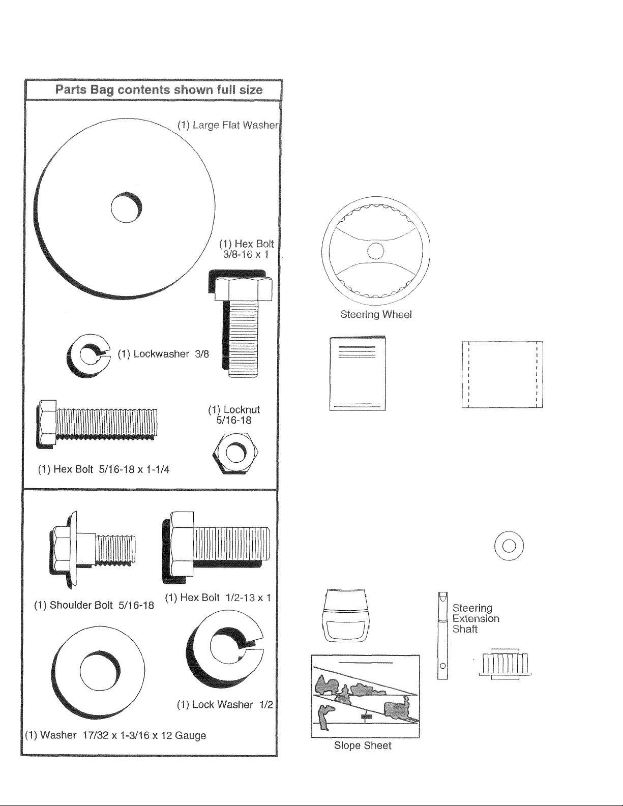
rONlFNFSO^ HARDWí.t.fe r
Parts packed separately in carton
4
Seat
ering
jleeve
Manual
Parts Bag
Parts bag contents not shown full size
(2) Shoulder Bolts
rc5)
(2) Washers 17/32
X 15/16 X 12 Gauge
Steering
Wheel
Insert
#1
(2) Gauge
Wheels
(2) Washers 3/8
X 7/8 X 14 Gauge
Steering Wheel
Adapter
o
(2) Center-
lock Nuts
(2) Keys
Page 6
lew tractor has been assembled at the factory with e
sure safe and proper operation of your tractor all pari
rrsci Jis
necessary to insure proper tightness.
«cepfion of those parts left unassembled for shipping purposi
s and hardware you r mb
. .-I nl yiflRED FOR ASSEMBLY
A socket wrench set will make assembly easier. Standard
wrench sizes are listed.
(1) 3/4" Socket w/drive ratchet Utility knife
(1) 9/16" wrench Tire pressure gauge
(2) 1/2" wrenches
When right or left hand is mentioned in this manual, it
means when you are in the operating position (seated
behind the steering wheel).
ro REMOVE TRACTOR FROM CARTON
UNPACK CARTON
• Remove all accessible loose parts and parts cartons
from carton (See page 5).
• Cut, from top to bottom, along lines on all four corners
of carton, and lay panels flat.
• Check for any additional loose parts or cartons and
remove.
ust be tiqhteried;
BEFORE ROLLING TRACTOR OFF SKID
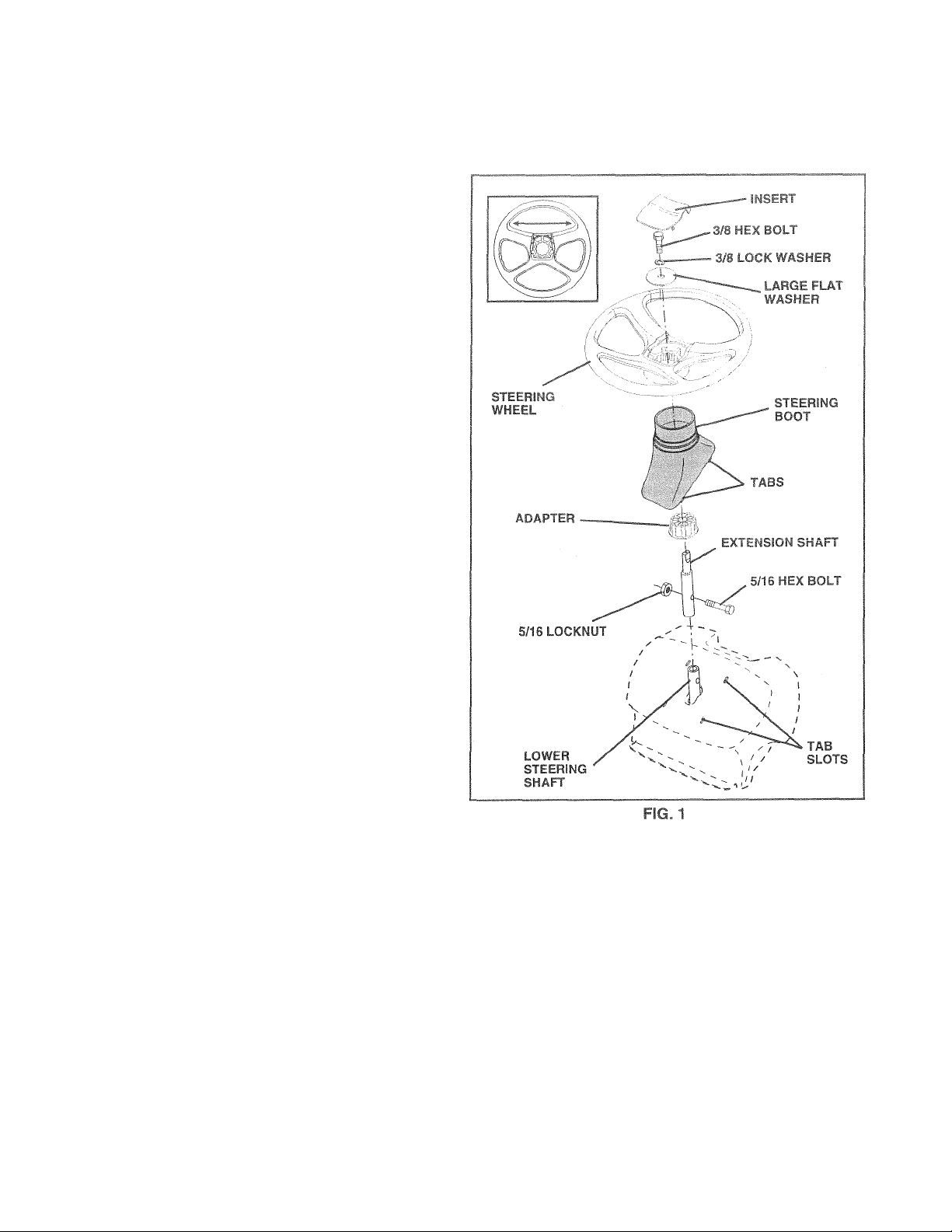
ATTACH STEERING WHEEL (See Fig. 1)
ASSEMBLE EXTENSION SHAFT AND BOOT
• Slide extension shaft onto lower steering shaft. Align
mounting holes in extension and lower shafts and
install 5/16 hex bolt and locknut. Tighten securely.
IMPORTANT: TIGHTEN BOLT AND NUT SECURELY TO
18-22 FT. LBS TORQUE.
• Place tabs of steering boot over tab slots in dash and
push down to secure.
INSTALL STEERING WHEEL
• Position front wheels of the tractor so they are pointing
straight forward.
• Slide steering wheel adapter onto steering shaft exten
sion.
• Position steering wheel so cross bars are horizontal
(left to right) and slide inside boot and onto adapter.
• Assemble large flat washer, 3/8 lock washer, 3/8 hex
bolt and tighten securely.
• Snap steering wheel insert into center of steering
wheel.
• Remove protective materials from tractor hood and
grill.
IMPORTANT: CHECK FOR AND REMOVE ANY STAPLES
IN SKID THAT MAY PUNCTURE TIRES WHERE TRACTOR
IS TO ROLL OFF SKID.
TO ROLL TRACTOR OFF SKID (See Opera
tion section for location and function of con
trols)
• Press lift lever plunger and raise attachment lift lever to
its highest position.
• Release parking brake by depressing clutch/brake
pedal.
• Place freewheel control in freewheeling position to
disengage transmission (See “TO TRANSPORT” in
the Operation section of this manual).
• Roll tractor forward off skid.
• Remove banding holding discharge guard up against
tractor.
Page 7
AsSf UBI -
HOW TO SET UF
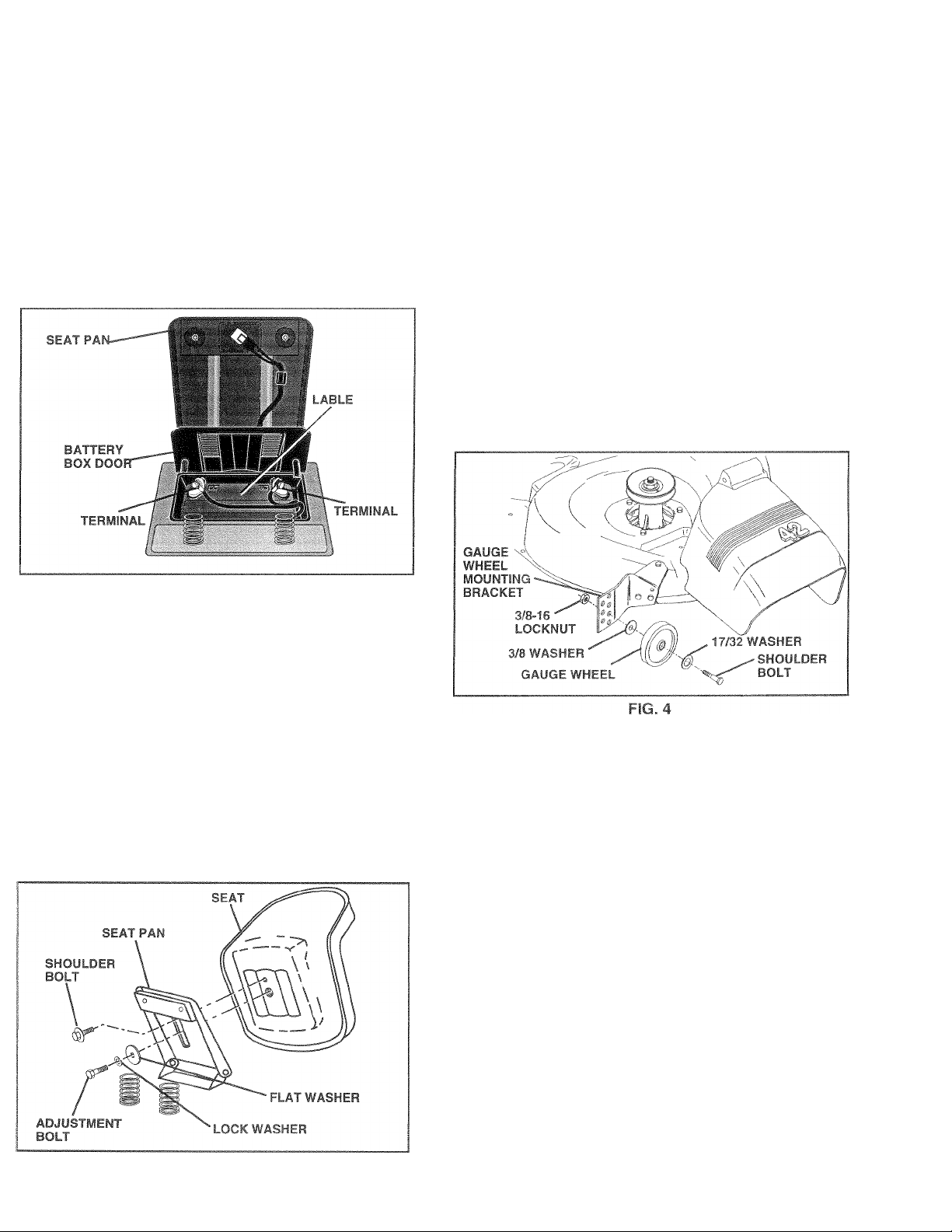
® Lift seat pan to raise
door.
if mi biiit r/1 . ,'if f-iij'irsii -liidyear
inaitated on hbai (H.j-I I.»' -tr-H r tHfininat)
charge battety m» ¡toi ,mum c 11 nt hou. -di t «(J amp(See "BATTER ■'' inCi JR1' )MF h RF F RONRiBlLITIFR
sprtion of fhis manual tot cliammg in'tnjchuns).
TRACTOR
!)
I,'I 'I ri(! I ;)^n baflory f)0'
rO MOWER
DECK (See F
The
proper position when operating fTiower. Bs sure they ars
pl> L « I ' C ■ II r I III.‘I 'It't ■ i! f I 'K’rn->h'"(-
* A -eintiib *j "ipf <i|-f| .<r <1 I ( (, r. fbt It 'ei
f I'ltj ►
‘ Adju.t ii>f Wf I 11'Jl r.d utfiiK. ti( ful'i ( <=e |GeD-
ilBT wr./vt P f urririC iff !CHrp«Hii '\wrotinn
-p T ,r« of till- hi mu li
® vvim mower in aesirea neigrii of cut posriiori, gauge
wheels should be assembled so they are slightly off the
ground. Install gauge wheel in appropriate hole with
shoulder bolt, 17/32 washer, 3/8 washer, and 3/8-16
locknut and tighten securely.
• Repeat for opposite side installing gauge wheel in
same adjustment hole.
g€
i/h
are designed to keep the mower deck in
FIG. 2
INSTALL SEAT (See Fig. 3)
Adjust seat before tightening adjustment bolt.
Remove cardboard packing on seat pan.
Place seat on seat pan and assemble shoulder
bolt.Tighten shoulder bolt securely.
Assemble adjustment bolt, lock washer and flat washer
loosely. Do not tighten.
Lower seat into operating position and sit on seat.
Slide seat until a comfortable position is reached which
allows you to press clutch/brake pedal all the way
down.
Get off seat without moving its adjusted position.
Raise seat and tighten adjustment bolt securely.
CHECK TIRE PRESSURE
The tires on your tractor were overinflated at the factory for
shipping purposes. Correct tire pressure is important for
best cutting performance.
• Reduce tire pressure to PSI shown in “PRODUCT
SPECIFICATIONS” on page 3 of this manual.
CHECK DECK LEVELNESS
For best cutting results, mower housing should be properly
leveled. See “TO LEVEL MOWER HOUSING” in the
Service and Adjustments section of this manual.
CHECK FOR PROPER POSITION OF ALL BELTS
See the figures that are shown for replacing motion and
mower blade drive belts in the Service and Adjustments
section of this manual. Verify that the belts are routed
correctly.
FIG.3
CHECK BRAKE SYSTEM
After you learn how to operate your tractor, check to see
that the brake is properly adjusted. See “TO ADJUST
BRAKE” in the Service and Adjustments section of this
manual.
Page 8

/ hi Ihf
s t ‘ f •;/I n ,‘,ii i r>,i( , '•nr- /ifj'i
■I M f I'vir / jrr-'iht r.-ii lufTf'ZFIV-'
,Hnhl '■! i~TRF >FMA’IntAfiO^^'^!rrArVCNfPnivi
¡tli^ QUAUi I I HOuUuT.
PLEASE REVIEW THE FOLLOWING CHECKLIST:
/ All assembly instructions have been completed.
/ No remaining loose parts in carton.
/ Battery is properly prepared and charged. (Minimum
1 hour at 6 amps).
Seat is adjusted comfortably and tightened securely.
All tires are properly inflated. (For shipping purposes,
the tires were overinflated at the factory).
Be sure mower deck is properly leveled side-to-side/
front-to-rear for best cutting results. (Tires must be
properly inflated for leveling).
/ Check mower and drive belts. Be sure they are routed
properly around pulleys and inside all belt keepers.
✓ Check wiring. See that all connections are still secure
and wires are properly clamped.
WHILE LEARNING HOWTO USE YOUR TRACTOR. PA Y
EXTRA ATTENTION TO THEFOLLOWING IMPORTANT
ITEMS:
/ Engine oil is at proper level.
/ Fuel tank is filled with fresh, clean, regular unleaded
gasoline.
/ Become familiar with all controls - their location and
function. Operate them before you start the engine.
/ Be sure brake system is in safe operating condition.
AsstmBU
8
Page 9

OPFRAÍiOr-
These symbols may appear on your tractor or in literature supplied with the product. Learn and understand their meaning.
I
nü A
BATTERY
CAUTION OR
WARNING
STOP
REVERSE FORWARD FAST
0^
©
ENGINE ON ENGINE OFF OIL PRESSURE LIGHTS ON
íB l\l
FUEL
CHOKE MOWER HEIGHT PARKING BRAKE
^ R N H L (®)|I
SLOW
lu
OVER TEMP
LIGHT
I
UNLOCKED MOWER LIFT
LOCKED
ATTACHMENT REVERSE
CLUTCH ENGAGED
ATTACHMENT
IGNITION
DANGER, KEEP HANDS AND FEET AWAY
CLUTCH DISENGAGED
NEUTRAL HIGH LOW
KEEP AREA CLEAR SLOPE HAZARDS
(SEE SAFETY RULES SECTION)
PARKING BRAKE
— =/<ÜI
I = ^
FREE WHEEL
(Automatic Models only)
Page 10
OPFRAtinM
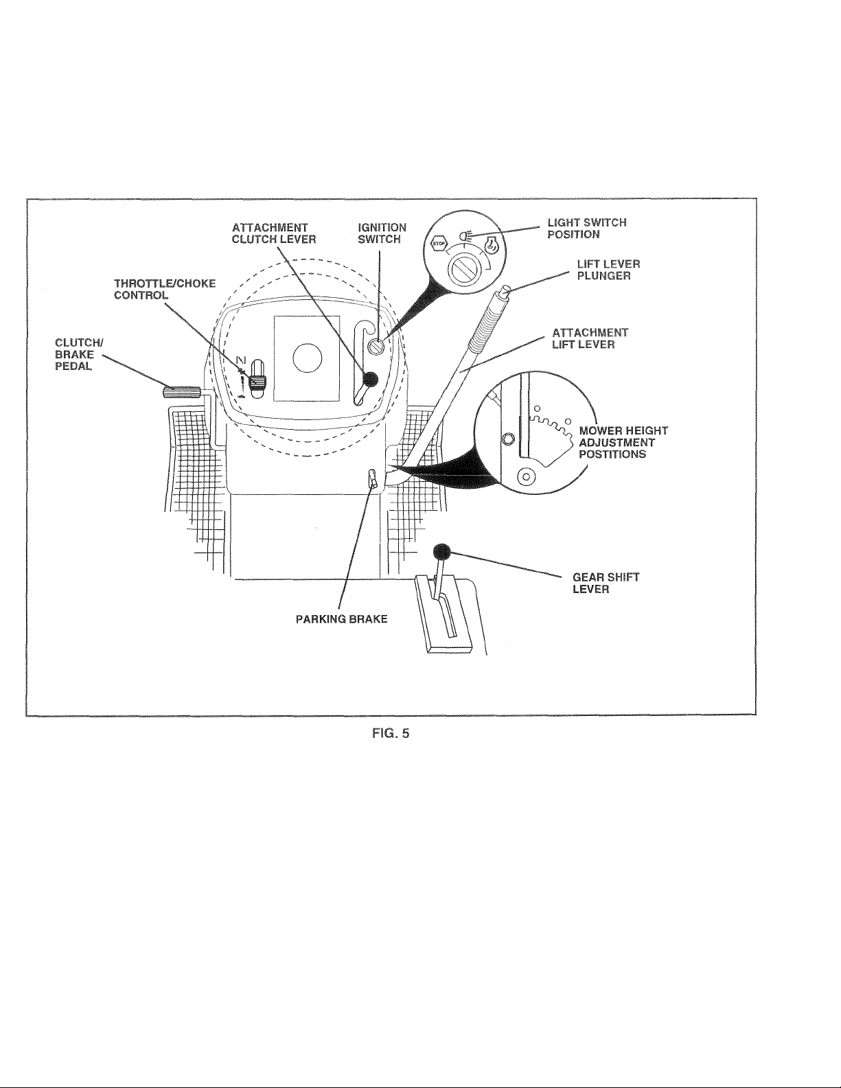
KNOW YOUR TRACTOR
^ r w. -niTi Mitf
• ■ rf ,h^- i|lj , i,G(l /if’l J « t .ri toi'iufdhliii-.f ^ /t UiSel, A'lthili !< tf>Y' t l' < f| (mK J'«i *i iiiiMil <v~
■ h i' '(I &' f<ir. it'jtf refercGf''
Our tractors conform to the safety standards of the American National Standards Institute.
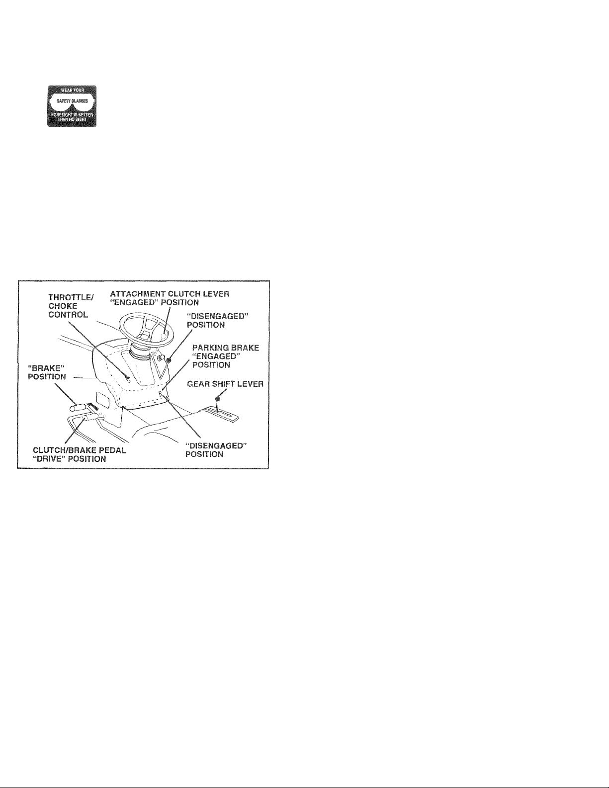
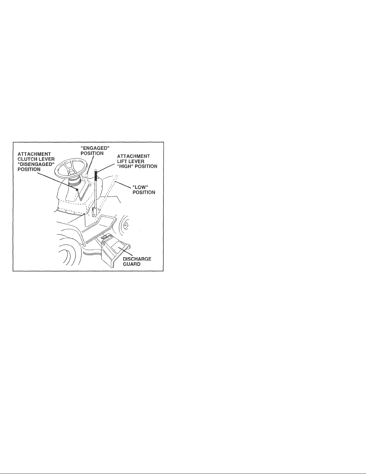
ATTACHMENT CLUTCH LEVER: Used to engage the
mower blades, or other attachments mounted to your
tractor.
LIGHT SWITCH: Turns the headlights on and off.
THROTTLeCHOKE CONTROL ^ Used for starting and
controlling engine speed.
CLUTCH/BRAKE PEDAL; Used for declutching and
braking the tractor and starting the engine.
PARKING BRAKE: Locks clutch/brake pedal into the
brake position.
GEAR SHIFT LEVER: Selects the speed and direction of
tractor.
ATTACHMENT LIFT LEVER - Used to raise and lower the
mower deck or other attachments mounted to your tractor.
LIFT LEVER PLUNGER: Used to release attachment lift
lever when changing its position.
IGNITION SWITCH: Used for starting and stopping the
engine.
10
Page 11
OPERA nnr^
The operati!
e< j!t Ili
/ jU» i'cift! '
safety maak orcr sp^/'taclf^i atan 1a< I ' aief
>fi of 311^ trsctof can restili io foreipo €
s'.~ 3wecJ'»ma§v f'U4iìfì
p£lf'. riTliig MS- JlP.-flft-r.'
HQW TO USE ^OUP TR4C TOR
TO SET PARKING BRAKE (See Fig. 6i
'y f ur tr jctor It equipped wth an op eratc r presence - eating
'tfiitrh When ‘'riQinr^ r riinriirg iftenpt the
opeiatoi to lfcdi/6 ihe sear without tim -eiting the potking
brake will shut off the engine.
• Depress clutch/brake pedal into full “BRAKE” position
and hold.
• Place parking brake lever in “ENGAGED" position and
release pressure from clutch/brake pedal. Pedal should
remain in “BRAKE” position. Make sure parking brake
will hold tractor secure.
FIG. 6
STOPPING (See Fig. 6)
MOWER BLADES -
• To stop mower blades.move attachment clutch leverto
“DISENGAGED” position.
GROUND DRIVE -
• To stop ground drive, depress clutch/brake pedal into
full “BRAKE” position.
• Move gearshift lever to neutral (N) position.
ENGINE -
• Move throttle control to slow position.
NOTE: Failure to move throttle control to slow position and
allowing engine to idle before stopping may cause engine
to “bacWire”.
• Turn ignition key to “OFF” position and remove key.
Always remove key when leaving tractor to prevent
unauthorized use.
® Never use choke to stop engine.
IMPORTANT: LEAVING THE IGNITION SWITCH IN ANY
POSITION OTHER THAN "OFF" WILL CAUSE THE
BATTERY TO BE DISCHARGED, (DEAD).
jjectsth
/hill
whi
! Op<
n cari
•ating
J
NOTE: Under certain conditions
idle withtfr ' ti.Jiii I'l.iiirn ii. . •
biL v<i( 1 uf .)(11 <
t<.| eno US vt,-h muj it
CAUTION' Alwdyi t-iop iracioi completely libedobove. before !eav
A
in§ tfit operator r pasilioti to empty
grasii catcher, etf
TO USE THRO ITL E COfiTBOL (See Fig. 6)
Always operate engini^ .at lUll throtil*'
• Operating engine a p. ; Ihan full IfTotile leduces the
battery charging 13te
• Full throttle offe'S Ihr, htst baqqinq md mower perfor
mance.
TO MO¥E FORWARD AND BACKWARD (See Fig. 6|
The direction and speed of movement is controlled by the
gearshift lever.
• Start tractor with clutch/brake pedal depressed and
gearshift lever in neutral (N) position.
• Move gearshift lever to desired position.
• Slowly release clutch/brake pedal to start movement.
IMPORTANT: BRING TRACTOR TO A COMPLETE STOP
BEFORE SHIFTING OR CHANGING GEARS. FAILURE
TO DO SO WILL SHORTEN THE USEFUL LIFE OF YOUR
TRANSAXLE.
TO ADJUST MOWER CUTTING HEIGHT
(See Fig. 5)
The position of the attachment lift lever determines the
cutting height.
• Grasp lift lever.
• Press plunger with thumb and move lever to desired
position.
Thecutting height range is approximately 1-1/2to 4". The
heights are measured from the ground to the blade tip with
the engine not running. These heights are approximate
and may vary depending upon soil conditions, height of
grass and types of grass being mowed.
• The average lawn should be cut to approximately 2-1/2
inches during the coo! season and to over 3 inches
during hot months. For healthier and better looking
lawns, mow often and after moderate.growth.
• For best cutting performance, grass over 6 inches in
height should be mowed twice. Make the first cut
relatively high; the second to desired height.
when tractor is standing
)!' tiJU-i JjSO; ITM>'
liif.Ml lit lhl~ pO-jibllity.
I f, -t (ii ..ii or^cs atHis.
11
Page 12
QPERATfOM
M, .tffr-R ri< T|
Your tractor is equipped with an operator presence sens-
1 » r, r>in I If I . >; ih- 1 > '
with the engine running and the attachment clutch engaged
will shut off the engine.
■ ■ f ir-> 1 Je itf I htip ii •_ 1 ijt
iUiC III blcicle^ f y §rt uugiii s r H ru locs * iuk h
conirol.
• TO STOP MOWER BLADES - disengage attachment
clutch control.
CAUTION: Do not operate the mower
without either the entire grass catcher,
on mowers so equipped, or the dis
A
charge guard in place.
HILLS
iOtf no in - < r ! J-.w> j
hills with slopes greater than 15° and I
Á
L
niiis.
• Avoid stopping or changing speed on hills.
• If slowing is necessary, move throttle control lever to
slower position.
• If stopping is absolutely necessary, push clutch/brake
pedal quickly to brake position and engage parking
brake.
• Move gearshift lever to 1st gear. Be sure you have
allowed room for tractor to roll slightly as you restart
movement.
• To restart movement, slowly release parking brake and
clutch/brake pedal.
• Make all turns slowly.
3west speed befe 3t£
do rm» a'|
g up or dowr
TO TRANSPORT
• Raise attachment lift to highest position with attach
ment lift control.
• When pushing or towing your tractor, be sure gearshift
lever is in neutral (N) position.
• Do not push or tow tractor at more than five (5) MPH.
NOTE: To protect hood from damage when transporting
your tractor on a truck or a trailer, be sure hood is closed
and secured to tractor. Use an appropriate means of tying
hood to tractor (rope, cord, etc.).
FIG. 7
12
Page 13

OPFBÄTlD^í
bEMiftE -ГЛВНЬ!? ÌHK tNr,iNF
(.PEÍ K‘í>ll IEí/F5 I |fj rfi
The engine
faeton
' fl .hJli'v '>! .Jit, i_.» !
HerTKw-niliilif dp/<li(. Ilf h diiü wi}
■ eiTiDt'c and read u.l level If пег£с,_зг/ add nil until
‘FULL m-rh'.n dipsticf i3 rcache J Do not oveifili
• Fot Luld weather operatioti joa .hould change oil tor
f. ustomer Rcopontibilitiec seGicn o* this rmnual)
• I change engine oil :re<= the Г u.-гс ner Respon<rir-ii;
tee beetlen in tfiis rnanuai
in your tractor he
already filled with sumr
dnd эь1ь« cap tight wait ioi a few betuiid^
otartir.y (Set GIL LI3COL1T i CrtART’ м the
. h
jeen shipped, from the
weight oil.
'el ground.
I >6 Л1 (Hinted: the
ADD GASOLINE
• Fill fuel tank. Use fresh, clean, regular unleaded
gasoline with a rninimurn of 87 octane. (Use of leaded
gasoline will increase carbon and lead oxide deposits
and reduce valve life). Do not mix oil with gasoline.
Purchase fuel in quantities that can be used within 30
days to assure fuel freshness.
IMPORTANT: WHEN OPERATING IN TEMPERATURES
BELOW 32“F(0°C), USE FRESH. CLEAN WINTER GRADE
GASOLINE TO HELP INSURE GOOD COLD WEATHER
STARTING.
WARNING: Experience indicates that alcohol blended
fuels (called gasohol or using ethanol or methanol) can
attract moisture which leads to separation and formation of
acids during storage. Acidic gas can damage the fuel
system of an engine while in storage. To avoid engine
problems, the fuel system should be emptied before stor
age of 30 days or longer. Drain the gas tank, start the
engine and let it run until the fuel lines and carburetor are
empty. Use fresh fuel next season. See Storage Instruc
tions for additional information. Never use engine or
carburetor cleaner products in the fuel tank or permanent
damage may occur.
CAUTION: Fill to bottom of gas tank
filler neck. Do not overfill. Wipe off any
spilled oil or fuel. Do not store, spill or
A
use gasoline near an open flame.
ТО START ENGINE
me
arting the
has run out of fue
fuel from the tank
o 1; .*•.(. _> |„ j . , [
pedal and set parking brake.
o HlaLt J^'ll bill 1* < C. I I ill I't. „Ml fJ*
® Mom Ut jlI-Iii> 1 r ;i.t> fM I!( L li /
® Mutfo throttl,^ f ntrol to ttlfi-,- j,..„ lliGI,
NOTE before -If«rfiiHj oh-i ti'*--wann'>nO m/id miling
procHrjiin—. bf-low
® Iriaenr iiir d u lire / Lrl'wi a'tu l rAflT”
posiLof. and rpip-j .fe k-y f. soon p ongme Da
not run btarter continuoioly ! )i iTi(»rt than fifteen se<
onds per minute. If the engine does not start after
several attempts, move throttle control to fast position,
wait a few minutes and try again. If engine still does not
start, move the throttle control back to the choke
position and retry.
WARM WEATHER STARTING (50° F and above)
• When engine starts, move the throttle control to the fast
position.
• The attachments and ground drive can now be used. If
the engine does not accept the load, restart the engine
and allow it to warm up for one minute using the choke
as described above.
COLD WEATHER STARTING ( 50° F and below)
• When engine starts, allow engine to run with the throttle
control in the choke position until the engine runs
roughly, then move throttle control to fast position. This
may require an engine warm-up period from several
seconds to several minutes, depending on the tem
perature.
• The attachments can also be used during the engine
warm-up period.
NOTE: If at a high altitude (above 3000 feet) or in cold
temperatures (below 32 F) the carburetor fuel mixture may
need to be adjusted for best engine performance. See “TO
ADJUST CARBURETOR” in the Service and Adjustments
section of this manual.
the
5l II!
»I
)r if the I
3 time tc
sition.
gir
dutch/
ZU :ition.
Page 14
opFRahon
MOWING TiPS
wt
• Tire»chains cannot
is attached to traete
<1 > • i lie f-» jr It- -I-n |, I ,j, Ci til I vi'id
|i i>,innv ',-0 ''a F/LLMUWFRHC'USihC t-
ih> S' lit - .nd n i,T fhK mafi'jHi
1 fit If-fi hai-d ^ide r.t ii>c vtr chr.Lld be used frr tom
Hill ly.
Drive so that clippings are discharged onto the area
that has been cut. Have the cut area to the right of the
tractor. This will result m a more even distribution of
dippings and more uniform cutting
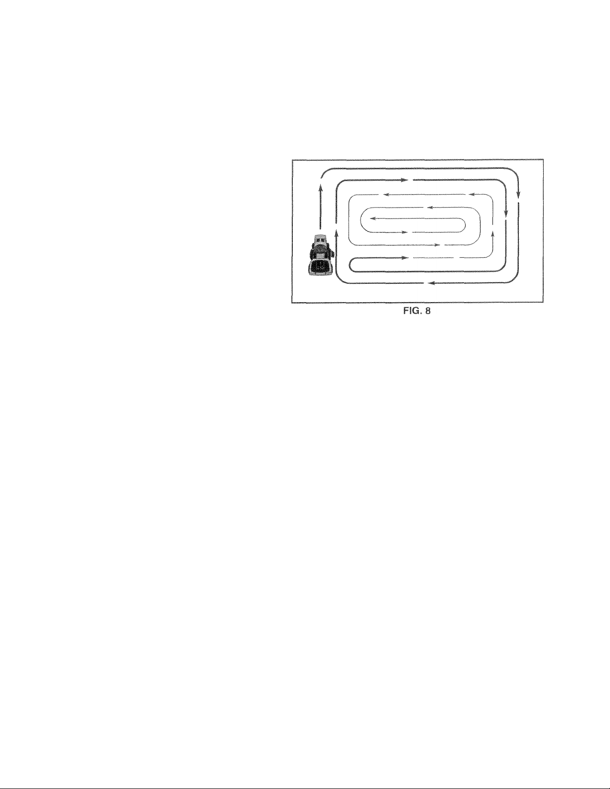
When mowing large areas, start by turning to the right
so that clippings will discharge away from shrubs,
fences, driveways, etc. After one or two rounds, mow
in the opposite direction making left hand turns until
finished (See Fig. 8).
If grass is extremely tall, it should be mowed twice to
reduce load and possible fire hazard from dried dip
pings. Make first cut relatively high; the second to the
desired height.
Do not mow grass when it is wet. Wet grass will plug
mower and leave undesirable clumps. Allow grass to
dry before mowing.
len me nOW€ 3us!nq
Always operate engine at full throttle when mowing to
assure better mowing performance and proper dis
charge of
material. Regulate ground speed by select-
I r u >» »1 HK< ih- f|. iV ' I '»'(I (
performance as well as the quality of cut desired.
vva^ii o|if rstiiii dtULO.i-.,r,T -ei* f' rt jtc jii‘i pH-
♦hat mII c. if tHfrp r. qi •- tn-.r f, rfi fvim t «
ihe ittarhrnent being u «-u
14
Page 15

CUSTOMER RESPONSSbi?. tfs?
MAINTENANCE SCHEDULE
FILL IN DATES
AS YOU COMPLETE
REGULAR SERVICE
Check Brake Operation
Check Tire Pressure
Check Operator Presence and
Interlock Systems
Check for Loose Fasteners
Sharpen/Replace Mower Blades
Lubrication Chart
Check Battery Level
Clean Battery and Terminals
Check T ransaxle Cooling
Adjust Blade Belt(s) Tension
Adjust Motion Drive Belf(s) Tension
Check Engine Oil Level
Change Engine Oil
Clean Air Filter
Clean Air Screen
Inspect Muffler/Spark Arrester
Replace Oil Filter (If equipped)
Clean Engine Cooling Fins
Replace Spark Plug
Replace Air Filter Paper Cartridge
Replace Fuel Filter
1 ' Change more often when operating under a heavy load or in high ambient temperatures.
2 ' Service more often when operating in dirty or dusty conditions.
3 - If equipped with oil filter, change oil every 50 hours.
4 - Replace blades more often when mowing in sandy soil,
✓
✓
ir'
✓
✓
✓
✓ 4
✓
✓ e
✓
✓
✓
✓
1^2,3 ✓
✓ 2
✓ 2
✓
RVICE DATES
✓ r
✓ 5
✓ s
✓ 1,2
✓ 2
✓
✓ 2
5 " if equipped with adjustable system.
6 - Not required if equipped with maintenance-free battery.
7 ' Tighten front axle pivot bolt to 35 ft.-lbs. maximum.
✓
✓
✓
✓
✓
Do not overtighten.
GENERAL RECOMMENDATIONS
The warranty on this tractor does not cover items that have
been subjected to operator abuse or negligence. To
receive full value from the warranty, operator must maintain
tractor as instructed in this manual.
Some adjustments will need to be made periodically to
properly maintain your tractor.
All adjustments in the Sen/ice and Adjustments section of
this manual should be checked at least once each season.
• Once a year you should replace the spark plug, clean
or replace air filter, and check blades and belts for
wear. A new spark plug and clean air filter assure
proper air-fue! mixture and help your engine run better
and last longer.
BEFORE EACH USE
• Check engine oil level.
• Check brake operation.
• Check tire pressure.
• Check operator presence and
interlock systems for proper operation.
• Check for loose fasteners.
LUBRICATION CHART
®SAE 30 OR 10W30 MOTOR OIL
©GENERAL PURPOSE GREASE
©REFER TO CUSTOMER RESPONSIBILiTiES “ENGINE” SECTION
IMPORTANT: DO NOT OIL OR GREASE THE PiVOT POINTS
WHICH HAVE SPECIAL NYLON BEARINGS. VISCOUS LUBRI
CANTS WILL ATTRACT DUST AND DIRT THAT WILL SHORTEN
THE LIFE OF THE SELF-LUBRICATING BEARINGS. IF YOU
FEEL THEY MUST BE LUBRICATED. USE ONLY A DRY. POW
DERED GRAPHITE TYPE LUBRICANT SPARINGLY.
15
Page 16

.-yStoMFR RFSpny<;iBtfc nn <>
TRACTOR
Always obser/e safety rules when performing any mainte
nance.
nv~~kHfKihrU
‘1 <■ I I ■- y ill C ' h' ri ll 1 Jl. I ('■ I It t ' *<'| p.ruj ~*i I- 11 >
£t hi«]r • pt Sfi ,n f'ntiPsigerii tr.en hrnte niu tboiijUatf j.
( fc. "w/ -An'iC-,1 ERAKt nine oe'-inre nj AHju.if~
i.iuiiis sectioii J tfiio indiiudli.
TIRES
• Maintain proper air pressure in all tires (See “PROD
UCT SPECIFICATIONS” on page 3 of this manual).
• Keep tires free of gasoline, oil, or insect control chemi
cals which can harm rubber.
• Avoid stumps, stones, deep ruts, sharp objects and
other hazards that may cause tire damage.
NOTE: To seal tire punctures and prevent flat tires due to
slow leaks, tire sealant may be purchased from your local
parts dealer. Tire sealant also prevents tire dry rot and
corrosion.
OPERATOR PRESENCE SYSTEM
Be sure operator presence and interlock systems are
working properly. If your tractor does not function as
described, repair the problem immediately.
• The engine should not start unless the clutch/brake
pedal is fully depressed and attachement clutch control
is in the disengaged position.
• When the engine is running, any attempt by the opera
tor to leave the seat without first setting the parking
brake should shut off the engine.
• When the engine is running and the attachment clutch
is engaged, any attempt by the operator to leave the
seat should shut off the engine.
• The attachment clutch should never operate unless the
operator is in the seat.
TO SHARPEN BLADE (See Fig. 10)
NOTE: We do not recommend sharpening blade - but if you
do, be sure the blade is balanced.
Care should be taken to keep the blade balanced. An
unbalanced blade will cause excessive vibration and even
tual damage to mower and engine.
• The blade can be sharpened with a file oron a grinding
wheel. Do not attempt to sharpen while on the mower.
• To check blade balance, you will need a 5/8" diameter
steel bolt, pin, or a cone balancer. (When using a cone
balancer, follow the instructions supplied with bal
ancer).
NOTE: Do not use a nail for balancing blade. The lobes of
the center hole may appear to be centered, but are not.
• Slide blade on to an unthreaded portion of the steel bolt
or pin and hold the bolt or pin parallel with the ground.
If blade is balanced, it should remain in a horizontal
position. If either end of the blade moves downward,
sharpen the heavy end until the blade is balanced.
BLADE CARE
For best results mower blades must be kept sharp. Re
place bent or damaged blades.
BLADE REMOVAL (See Fig. 9)
• Raise mower to highest position to allow access to
blades.
• Remove hex bolt, lock washer and flat washer securing
blade.
• Install new or resharpened blade with trailing edge up
towards deck as shown.
IMPORTANT: TO ENSURE PROPER ASSEMBLY,
CENTER HOLE IN BLADE MUST ALIGN WITH STAR ON
MANDREL ASSEMBLY.
• Reassemble hex bolt, lock washer and flat washer in
exact order as shown.
• Tighten bolt securely (27-35 Ft. Lbs. torque).
IMPORTANT: BLADE BOLT IS GRADE 8 HEAT TREATED.
16
Page 17

CUSTOMER RESPONSIBSI.O'IE-:
BATTERY
Your irs jr ric
cient for norn
battery with an automotive charge
• Keep battery and terminals clean.
t • < p i ifKi^ ti dh ilJhi
• Keep .srfiull vein hUe^, open.
• Recharge at 6-10 amperes for 1 hour.
NOTE: The original equipment battery on your tractor is
maintenance free. Do not attempt to open or remove caps
or covers. Adding or checking level of electrolyte is not
necessary.
TO CLEAN BATTERY AND TERMINALS
Corrosion and dirt on the battery and terminals can cause
the battery to “leak” power.
• Open battery box door.
• Disconnect BLACK battery cable first then RED bat
tery cable and remove battery from tractor.
• Rinse the battery with plain water and dry.
• Clean terminals and battery cable ends with wire brush
until bright.
» Coat terminals with grease or petroleum jelly.
• Reinstall battery (See “CONNECT BATTERY” in the
Assembly section of this manual).
I . h 'S'fr i- riiL)ic charging of the
ia
ind ti
V-BELTS
Check V-belts for deterioration and wear after 100 hours of
operation and replace if necessary. The belts are not
adjustable. Replace belts if they begin to slip from wear.
:em which is suffi-
vvm extend its life.
lithe
gh mu
)U;
improve s;tart
will result
32°F. Chi
p* * ^'Ll.
' hMii 'f le c
Check the crankcase oil level before starting the engine
and after each eight (8) hours of operation. Tighten oil fill
cap/dipstick securely each time you check the oil level.
TO CHANGE ENGINE OIL (See Fig. 11)
Determine temperature range expected before oil change.
All oil must meet API service classification SF, SG or SH.
• Be sure tractor is on level surface.
• Oil will drain more freely when warm.
• Catch oil in a suitable container.
• Remove oil fill cap/dipstick. Be careful not to allow dirt
to enter the engine when changing oil.
• Remove drain plug.
• After oil has drained completely, replace oil drain plug
and tighten securely.
• Refill engine with oil through oil fill dipstick tube. Pour
slowly. Do not overfill. For approximate capacity see
“PRODUCT SPECIFICATIONS” on page 3 of this
manual.
• Use gauge on oil fill cap/dipstick for checking level. Be
sure dipstick cap is tightened securely for accurate
reading. Keep oil at “FULL” line on dipstick.
in*
in i* ■{
eck
yc)urenc
jngi
ineÌ dam;age frorn running low on oil.
arif
th-etractiDr is nO’t used for 25 hours in on«8 yean
lti-visc(
Dsity oils (5W30, 10W3
Id weather, these multi-viscos
g in CO
d oil CO
Tease’
line oil level more frequently tc) avoid
very 2£
attere
insumption when used.5'
i hours of operation or a
0 etc.)
;ity oils
it ¡03Si
TRANSAXLE COOLING
Keep transaxie free from build-up of dirt and chaff which
can restrict cooling.
ENGINE
LUBRICATION
Only use high quality detergent oil rated with API service
classification SF, SG, or SH. Select the oil’s SAE viscosity
grade according to your expected operating temperature.
SAE VISCOSITY GRADES
■20^
“F
°C -30“
TEMPERATURE RANGE ANTICIPATED BEFORE NEXT OIL CHANGE
0“ 30° 32° 40°
20“ -10° 0“ 10“ 20“ 30“ 40“
60° 80° 100°
FIG. 11
17
Page 18

*: Ur»'OIV!EP RESPONSIRPlJtlFS
IR FILTER {Sg6 Fig
3ur efiaine will r
Clean the foam pre-cleaner after every 25 hours of opera-
« f i'f I, fUCi
!i if •! C'l ti '•r; ' r< "r<i n ■>< -I{ <r'ir ‘
(.1 „< < <► ,-Mr-i ,ii..re .-rif 11 ij I <i
Pfcin j ih knobisi a,l•^ ' '«ver
H . -FRvILE FftE-n b/^rJER
C Ik'i^ fr.an pf€ r-iearer off ‘.atinilqc
wasn It in iiquia detergent ana water.
Squeeze it dry in a clean cloth.
Saturate it in engine oil. Wrap it in clean, absorbent
doth and squeeze to remove excess oil.
If very dirty or damaged, replace pre-cleaner.
Reinstall pre-cleaner over cartridge.
Reinstall cover and secure with knob(s).
TO SERVICE CARTRIDGE
Remove cartridge nut.
Carefully remove cartridge to prevent debris from en
tering carburetor. Clean base carefully to prevent
debris from entering carburetor.
Clean cartridge by tapping gently on flat surface. If very
dirty or damaged, replace cartridge.
Reinstall cartridge, nut, precleaner, cover and secure
with knob(s).
IMPORTANT: PETROLEUM SOLVENTS, SUCH AS
KEROSENE, ARE NOT TO BE USED TO CLEAN THE
CARTRIDGE. THEY MAY CAUSE DETERIORATION OF
THE CARTRIDGE. DO NOT OIL CARTRIDGE. DO NOT
USE PRESSURIZED AIR TO CLEAN OR DRY
CARTRIDGE.
( U h » •■j. /!, iJ !.-U ‘ !• f ■ r h'}« r
12)
CLEAN AiR SCREEN (See Fig. 13|
Air screen must be kept free of dirt and chaff to prevent
engine damage from overheating. Clean with a wire brush
or compressed air to remove dirt and stubborn dried gum
I It «as.
ENGINE COOUNC FWiS (Stt Ftg iT|
ufiy t‘j I dill or oil t.mii fer.yiue ‘“Olii g in' to
pre 'ent er«j ne dariiagp ff- -iri cn'erh-ating
• Remm«^ crfrom biow^i hnu=nng 'nd iirt hou^-ing
ahd dipstii.k tube dosembly off engine.
• Cover oil fill opening to prevent entry of dirt.
• Use compressed air or stiff bristle brush to thoroughly
clean engine cooling fins.
• To reassemble, reverse above procedure.
18
Page 19

CUSTOMER RFSPONSIBSt ITIF?.
MUFFLER
t and replace corroded muffler and spark arrester (if
inspe
equipped)
SPARK PLUGS
Rf-Ol - -per*' plil'J- »1 tht br-qirininj of fTi'/'K.iJ
't-d' : ' f eftrr .'j*i h'-ui )f ''i ^ra.irn
occurs first Spark plug type ana gap setting are 5ho#n a i
PRODUCT SPECIF ICATIOr J5" < >n (.age 5 of thl'- manuai
IN-LINE FUEL FILTER (See Fig. 14)
The fuel filter should be replaced once each season. II fuel
filter becomes dogged, obstructing fuel flow to carburetor,
replacement is required.
• With engine cool, remove filter and plug fuel line
sections.
• Place new fuel filter in position in fuel line with arrow
pointing towards carburetor.
• Be sure there are no fuel line leaks and clamps are
properly positioned.
• Immediately wipe up any spilled gasoline.
-.‘V i f t .lift [i:i Irirniv,'
CLEANING
• Clean engine, battery, seat, finish, etc. of all foreign
matter.
• Keep finished surfaces and wheels free of all gasoline,
oil, etc.
• Protect painted surfaces with automotive type wax.
We do not recommend using a garden hose to dean your
tractor unless the electrical system, muffler, air filter and
carburetor are covered to keep water out. Water in engine
can result in a shortened engine life.
19
Page 20

A
AND AD-IU^^TWFNTc
CAUTION: BEFORE PERFORMING ANY SERVICE OR ADJUSTMENTS:
''iytrn/i: f edf^'lu^ly ctr » »»s . r» *• .
Place motion control lever in neutral (N) position.
-.»»«'»■< » i? i,< Ihort.
I tjrn .ijMitioii kef OFF ann №frto.ie kti#
Wake sjre tne blades ana ali moving puitt riavt completely stopped.
Disconnect spark plug «Ire from spark plug and place wire where it cannot come In contact
with plug.
TRACTOR
TO REMOVE MOWER (See Fig. 15)
yower will be easierto remove from the right side of tractor.
• Place attachment clutch in “DISENGAGED” position.
• Move attachment lift lever forward to lower mower to its
lowest position.
• Roll belt off engine pulley.
• Disconnect clutch rod from clutch lever by removing
retainer spring.
• Disconnect anti-sway bar from chassis bracket by
removing retainer spring.
• Disconnect suspension arms from rear deck brackets
by removing retainer springs.
• Disconnect front links from deck by removing retainer
springs.
• Raise lift lever to raise suspension arms. Slide mower
out from under tractor.
IMPORTANT: IF AN ATTACHMENT OTHER THAN THE
MOWER IS TO BE MOUNTED TO THE TRACTOR, THE
R.H. AND L.H. SUSPENSION ARMS MUST BE REMOVED
FROM TRACTOR.
TO INSTALL MOWER (See Fig. 15)
• Raise attachment lift lever to its highest position.
® Slide mower undertractorwith discharge guard to right
side of tractor.
® Lower lift lever to its lowest position.
• install mower in reverse order of removal instructions.
CLUTCH ROD
SUSPENSION
ARMS
RETAINER
SPRING
ANTI-SWAY BAR
CLUTCH LEVER
RETAINER
SPRING
ENGINE
/' PULLEf
RETAINER
SPRINGS
(BOTH SIDES)
RETAINER
SPRINGS
(BOTH SIDES)
FIG. 15
20
Page 21

SERVICE AND AOjySTM?>i ? s
.f i I vfi mimm hoosimg
Adjust the mower while tractor is parked on level ground or
r/lit SIM .r fii| <1, 111, -to"
“PRODUCT SPECIFICATIONS” on page 3 of this manual).
ilhiv-jUu M f*i. jtillifl i u iJi if,, Ui ll/. <j>i >
''“.nr rriCiA t
' IL'F lUolDt AUjUSryLfJl (^ee Figo ¡band 17)
Raise mower to rte highest o.^!lion
• At the midpoini of both sides of mower, measure height
from bottom edge of mowerto ground. Distance “.A” on
both sides of mower should be the same or within 1/4"
of each other.
• If adjustment is necessary, make adjustment on one
side of mower only.
» To raise one side of mower, tighten lift link adjustment
nut on that side.
• To lower one side of mower, loosen lift link adjustment
nut on that side.
NOTE; Three full turns of adjustment nut will change
mower height about 1/8“.
• Recheck measurements after adjusting.
I riv ■!!) I > I' 'I ' I If > r . ,t ( I *
IMPORTANT: DECK MUST BE LE'
THE FOLLOWING FRONT-TO-BA
NECESSARY, BE SURE TO ADJUS
EQUALLY SO MOWER Wll
' HA
i<> . ' mM th !■< • l•IM!|ll , .It ih Hi n'f . h Ij'liig
si'fHJillPt' Ah-1 tri^.ftiii‘1 ip|, I, iirat^ly i/f‘to
1/'" lowM' hai. .1 ( rf r-i wh n iW ifi-wm si> i hint^-si
position.
Check t)diu''trT,tnt o,t iiohf ct f^easurp dist'jncfc ‘ D ■ directly Ml troiH a< id beriii iif ffic riir!nJiel at bottom
edge ot triuwer hou^irio w ■fn.'vu,
• Before rriakiriq any riPi'j .-ri suiucifr.etits checHhat
both f tout links ai'joiiUoliiiSfcriyff! Boiti links should be
approxirnately 10 3/8“.
• If links are not equal in length, adjust one link to same
length as other link.
• To lower front of mower loosen nut “E” on both front
links an equal number of turns.
• When distance “D” is 1/8" to 1/2" lower at front than
rear, tighten nuts “F” against trunnion on both front
links.
• To raise front of mower, loosen nut “F” from trunnion on
both front links. Tighten nut “E” on both front links an
equal number of turns.
• When distance “D” is 1/8" to 1/2" lower at front than
rear, tighten nut “F” against trunnion on both front links.
• Recheck side-to-side adjustment.
e rigs. 1 o ana i a)
VEL SIDE-TO-SIDE. IF
\CK ADJUSTMENT IS
5TBOTH FRONT LINKS
TAY LEVEL SIDE-TO^
Page 22

SFRV'Ce AND ADJir^TMFNTS
r' REPLACE MOWER ftl DRIVE BELT
(See fig. 20)
The mower blade drive belt may be replaced without tools.
XL.. ..X-. __ ■—I r-_—- larking brake.
1 I < u|- tyu , „ 'i
< TO REMOVE
M* 'WtR in ini- I of thic niaii'J il|.
‘ '.V ri-r,e!i uff buih .ndndi. i pulltyx ii(d idler pulleys.
* ? ull t'“!? :iMj/ f- iin mower
PEI I liJSTALLATIO'l
‘ III tall h-w bfcli in leveiac u der cd tarnoval.
* Make ii>f-h^lTi' nallpulto>H]rn vd inside all belt
yiiide,
* Install mower in reverse order of removal instructions.
FIG. 20
TO ADJUST BRAKE (See Fig. 21)
Your tractor is equipped with an adjustable brake system
which is mounted on the right side of the transaxle.
If tractor requires more than six (6) feet stopping distance
at high speed in highest gear, then brake must be adjusted.
• Depress clutch/brake pedal and engage parking brake.
• Measure distance between brake operating arm and
nut “A” on brake rod.
• if distance is other than 1-1/2", loosen jam nut and turn
nut “A” until distance becomes 1-1/2". Retighten jam
nut against nut “A”.
® Road test tractor for proper stopping distance as stated
above. Readjust if necessary. If stopping distance is
still greater than six (6) feet in highest gear, further
maintenance is necessary. Contact your nearest au
thorized service center/department.
TO REPLACE MOTION DRIVE BELT (See Fig. 22)
Park the tractor on level surface. Engage parking brake.
For assistance, there is a belt installation guide decal on
bottom side of left footrest.
• Remove mower (See “TO REMOVE MOWER” in this
section of this manual.)
® Remove belt from stationary idler and clutching idler.
• Pull belt slack toward rear of tractor. Remove belt
upwards from transaxle pulley by deflecting belt keep
ers.
• Pui! belt toward front of tractor and remove downwards
from around engine pulley.
• Install new belt by reversing above procedure.
22
FIG. 22
Page 23

SERVICE AND ADJUS ГМГН i
c
ro AfijiJSi #Н£Г1 M iG t m fN I
It Ч! I ij f ■ ‘ b I "f h 1 .1 Л1* I f.- il i' Hfjllii
ht' (KI-< ^! -Ojir. t,f 1-Inni f !■ i/i i'■ к , ,.i>‘' li^-r
I'lg1 aP !r_ 'Iif-I' !• I (1.
-- ti- 'f t*',l, rn r.'l '
FRONT WHEEL ГОЕ IN/CAMBER
The front wheel toe-in and camber are not adjustable on
your tractor. If damage has occurred to affect the front
wheel toe-in or camber, contact your nearest authorized
service center/department.
TRANSAXLE SHIFTER LINKAGE AND ADJUSTMENT (See Figs. 23A and 23B)
The transaxle should be in neutral when the gear shift lever
is in the neutral (N) (lock gate) position. The adjustment is
preset at the factory; however, if adjustment is needed,
proceed as follows:
• Make sure transaxle is in neutral (N).
® Loosen two locknuts on tie rod.
• Turn center rod until gearshift lever falls into neutral
lock gate on fender console.
• Tighten locknuts securely.
Til flFMtoTt ^
FOR REPAII
(See Fio, 241
® Block up axle secure'
I f -I
t =<U> i-I
рчч)
iar whei
• Repair lire and reaaSferrto
NOTE: To seal tire punctures and prevent flat tires due to
slow leaks, tire sealant may be purchased from your local
parts dealer. Tire sealant also prevents tire dry rot and
corrosion.
WASHERS
RETAINING
RING
ind Wi 8rS 10 BIfOV/
re key - Do
FIG. 23A
AXLE COVER
SQUARE KEY
(REAR WHEEL ONLY)
Page 24

AND ALUlf*.‘-ii.lt; rii ■
■ ^ ■ ■ i,f" I .iliiiNE
tfi F F;.i fLRY REPLACINi F'. sTBE l3f:C rig,.i, ai> ait»* . '•
rSeCi Ffg. 25|
CAUTIGH; Lead-acid batteries generateexpiosive gases Keep sparks, flame
and smoking materiais away from bat
A
if ycur battery is too weak to start the engine, it should be
recharged. (See 'BATTERY" in the CUSTOMER RESPONSIBILltlES section of this mariuali.
It “jumper cables" are used for erriergency starting, follow
this procedure;
IMPORTANT: YOUR TRACTOR IS EQUIPPED WiTH A 12
VOLT rJEGATlVE GROUNDED SYSTEM, THE OTHER
VEHICLE MUST
GROUNDED SYSTEM DO NOT USE YOUR TRACTOR
BATTERY TO START OTHER VEHICLES,
TO ATTACH JUMPER CABLES * Connect each end of the RED cable to the POSITIVE
(+) terminal of each battery, taking care not to short
against chassis.
* Connect one end of the BLACK cable to the NEGA
TIVE (-) terminal of fully charged battery.
* Connect the other end of the BLACK cable to good
CHASSIS GROUND, away from fuel tank and battery.
TO REMOVE CABLES, REVERSE ORDER * BLACK cable first from chassis and then from the fully
charged battery.
* RED cable last from both batteries.
teries. Always wear eye protection
when around batteries.
ALSO BE A 12 VOLT NEGATIVE
CAtlTIOli,. [ic-i fiot eryort battery termi
nals by allowing a wrertch or any other
objecfto ecnlact both terminals at the
.same time. Before connecting battery,
remove metal bracelets, wristwatcfi
bands/ingSjStc.
A
Positive terminal must be connected
first to prevent sparking from acciden
tal grounding.
Lift seat pan to raised position and open battery bo;<
door.
Disconnect BLACK battery cable first then RED battery
cable and carefully remove battery from tractor.
Install new battery with termir.aLs in same position as
old battery.
First connect RED batteiy cable to positive (+) terminal
with hex bolt and keps nut as shown. Tighten securely.
Connect BLACK grounding cable to negative (-) termi
nal with remaining hex bolt and keps nut. Tighten
securely.
Close battery box door.
SEAT PAN
BATTERY
BOX DOOR
POSITIVE TERMINAL
NEGATIVE TERMINAL
/
CHASSIS-
CABLES
CHARGED
BATTERY
POSITIVE TERMINAL NEGATIVE TERMINAL
FIG. 25
FIG. 26
24
Page 25

SERVICE AND ADJUSTMENTS
TO REPLACE HEADLIGHT BULB
Raise hood.
FRjII bulb holder out of the hole in the backside of the
gmi
Replace bulb in holder and push bulb holder securely
back into the hole in the backside of the grill.
kjiuat: i
ITLPI AflU riLI AYR
■ nr I i1ia(!i-‘J liilto rir, < IC if «U.^S f J run
^oorly, stop running, or prevent it from starting.
Check wiring. See electrical wiring diagram in the
Repair Parts section.
I RFPi Ale fuse
pi ir /tfilh ii! .iiip , ¡furii'.iiVi lyp- i iijg ir. ru t The
i noWt.r i located Hlhind the d i'11
O REMOVE HOOD AND GRILL ASSEMBLY
5ee Fig. 28)
Raise hood.
Unsnap headlight wire connector.
Stand in front of tractor. Grasp hood at sides, tilt toward
engine and lift oft of tractor.
ENGINE
TO ADJUST THROTTLE CONTROL CABLE (See Fig. 29)
The throttle control has been preset at the factory and
tfTii lit .ho ■ b*- ne> b • ;. (I , u|uRrnt-m «
(R A III»! <i hf l< A) ijlr f. If*- Inu' -hilKj 1 d>l It <|1I. 1 I I
r> . (*.< f ,1. p.(.f,. k1 f .||. uH
‘Jl... •'t-iniitiiy ni If.I >111- I.l-dlevr.
!| -1 R. )>/* If, . h, kf- po iriftf" - h’A'Iv fU')V If 'f I ff 'm
. hot, I ; iw t o trill
t n d tfl iiflulfc''/ inij'i 'C'lfiii lUfitiol Ilvoi .h(J tiol<
I‘i (|('Vt rn.ii pRtp unp up If hoifeC A ¿If- rii‘t alipn'-d
i . I rs > f iUipsi'I; w di'drTH«'eth'LStl< c ttfcuifil laT
,ail Rigned. Tighten olamp ocrew securely.
TO ADJUST CARBURETOR
The carburetor has been preset at the factory and adjust
ment should not be necessary. However, minor adjust
ment may be required to compensate for differences in fuel,
temperature, altitude or load. If the carburetor does need
adjustment, see engine manual.
High speed stop is factory adjusted. Do not adjust damage may result.
IMPORTANT: NEVER TAMPER WITH THE ENGINE
GOVERNOR, WHICH IS FACTORY SET FOR PROPER
ENGINE SPEED. OVERSPEEDING THE ENGINE ABOVE
THE FACTORY HIGH SPEED SETTING CAN BE
DANGEROUS. IF YOU THINK THE ENGINE-GOVERNED
HIGH SPEED NEEDS ADJUSTING, CONTACT YOUR
NEAREST AUTHORIZED SERVICE CENTER/
DEPARTMENT, WHICH HAS PROPER EQUIPMENT AND
EXPERIENCE TO MAKE ANY NECESSARY
ADJUSTMENTS.
FIG. 28
FIG. 29
25
Page 26

Imr
the
iea
if th. A/iiI
^ ii!JÌ *OfJ r!t jer i* K" tue traete! w>ti
ga-^c-iinr SI fhe tar«l« irisside h tuilding
•vtieie fumes mai reach an open flame
A
or sparir Ailotfi the engine to cool
i?«»fote storing in any enclosme
it the €
. -lM‘
TRACTOR
Remove mower from tractor for winter storage. When
mower is to be stored tor a period of time, clean it thor
oughly, remove all dirt, grease, leaves, etc. Store in a
clean, dry area.
• Clean entire tractor (See “CLEANING" in the Customer
Responsibilities section of this manual).
• Inspect and replace belts, if necessary (See belt re
placement instructions in the Service and Adjustments
section of this manual).
• Lubricate as shown in the Customer Responsibilities
section of this manual.
• Be sure that all nuts, bolts and screws are securely
fastened. Inspect moving parts tor damage, breakage
and wear. Replace it necessary.
• Touch up all rusted or chipped paint surfaces; sand
lightly before painting.
BATTERY
• Fully charge the battery tor storage.
• After a period of time in storage, battery may require
recharging.
• To help prevent corrosion and power leakage during
long periods of storage, battery cables should be
disconnected and battery cleaned thoroughly (see “TO
CLEAN BATTERY AND TERMINALS” in the Cus
tomer Responsibilities section of this manual).
leave cables disconnected and place
cables where they cannot come in contact with battery
terminals.
If battery is removed from tractor for storage, do not
store battery directly on concrete or damp surfaces.
FUEL SYSTEM
mP Z-r.if iV- P j ,M-Ul 'PI I.i r Ri-.'MJI DIvi
‘'LF.i.jitL ft OlVi t I) i-i r I' 11 !l h L t s 1 I r“' *-Ji I
' , ' ft-MP'Pt ilpH M - I AhbDH*- ,()h FUl I ^|l ‘ f R
fuel hole jf r*TJf DUhliJO ruRepE <>L iC
FXFEBlLri'. E iHDlf A FES THAT ALCOHOl ElFNDED
Ff'Ei r (C / .^/--.OHC'L OR i.EItJO EFhAfJOL uR
METHAN' -L. I,AM AlTR/CT MOI -TUPE WHICH LEADS
TO SEPARATION AND FORMATION OF ACIDS DURING
STORAGE ATIDI' PAS CAN DmMAuE tHE FUEL
Y=TFM r-F AN ENGINE WHILE IN SFORA SF
• Drain the fuel tank.
• Start the engine and let it run until the fuel lines and
carburetor are empty.
• Never use engine or carburetor cleaner products in the
fuel tank or permanent damage may occur.
• Use fresh fuel next season.
Fuel stabilizer is an acceptable alternative in
minimizing the formation of fuel gum deposits during stor
age. Add stabilizer to gasoline in fuel tank or storage
container. Always follow the mix ratio found on stabilizer
container. Run engine at least 10 minutes after adding
stabilizer to allow the stabilizer to reach the carburetor. Do
not drain the gas tank and carburetor if using fuel stabilizer.
ENGINE OIL
Drain oil (with engine warm) and replace with clean engine
oil. (See “ENGINE” in the Customer Responsibilities
section of this manual).
CYLINDER(S)
• Remove spark plug(s).
• Pour one ounce of oil through spark plug hole(s) into
cylinder(s).
• Turn ignition key to “START” position tor a few seconds
to distribute oil.
• Replace with new spark plug(s).
• Do not store gasoline from one season to another.
• Replace your gasoline can if your can starts to rust.
Rust and/or dirt in your gasoline will cause problems.
• If possible, store your tractor indoors and cover it to
give protection from dust and dirt.
• Cover your tractor with a suitable protective cover that
does not retain moisture. Do not use plastic. Plastic
cannot breathe which allows condensation to form and
will cause your tractor to rust.
IMPORTANT: NEVER COVER TRACTOR WHILE ENGINE
AND EXHAUST AREAS ARE STILL WARM.
26
Page 27

TROUi
11
.r
E.
HOOTING POINT
1 2, Engine not “CHOKED" properly.
1 3. Engine flooded.
1 4. Bed spark plug.
5. Dirty air filter.
UIIIV lur,:! illi“!
Wlfil'lfiir in IlifO
8. Loose or damaged wiring.
> 1 'bum ici UI 11 1 ijii il If i 4
10. Engine valves out of adjustnisn!.
■lard to start ) Dtny -ii lilt r
Djil |i.'!
W t 'll H i ' t !li( f I
+ liidy ftjt 1 lilt 1
stall- 01 dirtv iu<-l
t L'(i‘ e u li iiii jc il vuitriQ
Gott irt ti 1 sut f iJii* tmi nt
'■ Liigiimvil -ni of aniU'triirnt
ingine wili not turn over
1. Clufch/brake pedal not depressed. 1. Depress clutch/brake pedal.
2, Attachment clutch is engaged. 2. Disengage attachment clutch.
3. Weak or dead battery.
4. Blown fuse.
5. Corroded battery terminals.
6. Loose or damaged wiring. 6. Check all wiring.
7. Faulty ignition switch.
8, Faulty solenoid or starter.
9. Faulty operator presence switch(es).
I 2. See TO START ENGINE'Mn Operaiiori section,.
&l tank.
1 3, Wait several miniitss before attempting to start,
1 4. Replace spark plug,
1 ( i- )(V'l pi r ,ll (|l|, (
s . ftt-pl 1- >11-1 iipo
1 r ' tril.i kiL'Cftf W' jrbu' t, f . wTit* -r.
1 p- 1 liiif jn'i 1,-ui-i till 1 fidfc
1 8. Check all wiring.
1 ) t- inAfjjii i> |i -ru|( - A(i, (,!,-> t>.
cefrrioi'!.
i( 1 1,1 1, t ^r. o lihui: ;d < rj ■tr iaF o.oh, h.
' t lO/rcpI i c ail filler
Hcpij ' pirl- plUJ
ft r h'iiu «!' pi V f ''•■'tl* r.
\ 1 Rfpiate IIIt! filiti
t Diam iusi tank and itfili wnh fr‘->-ii <41- jIuf
b. ChecK all wiring.
7 "rt To A'i|U''T CaiDuretur in 3tr.Ito 4j|u->tmtr>t'
section.
8 Coutil t an autriorLfcd .^rvi ■ i ,-riif i/dcfartmcri
3. Recharge or replace battery.
4. Replace fuse.
5. Clean battery terminals.
7. Check/replace ignition switch.
B, Check/replace solenoid or starter.
9. Contact an authorized service center/department.
ngine clicks but wil! not 1. Weak or dead battery.
:art
jss of power
2. Corroded battery terminals. 2. Clean battery terminals.
3, Loose or damaged wiring.
4. Faulty solenoid or starter.
1. Cutting too much grass/too fast.
2. Throttle in “CHOKE” position.
3. Build-up of grass, leaves and trash under mower. 3, Clean underside of mower housing.
4. Dirty air filter.
5. Low oil level/dirty oil
6. Fauify spark plug.
7. Dirty fuel filter.
8. Stale or dirty fuel.
9. Water in fuel.
10. Spark plug wire loose.
11. Dirty engine air screen/fins.
12. Dirty/clogged muffler.
13. Loose or damaged wiring.
14. Carburetor out of adjustment.
15. Engine valves out of adjustment.
cessive vibration
1. Worn, bent or loose blade.
2. Bent blade mandrel.
3. Loose/damaged part(s).
1. Recharge or replace battery.
3. Check all wiring.
4. Check/replace solenoid or starter.
1. Set in “Higher Cuf position/reduce speed.
2. Adjust throttle control.
4. Clean/replace air filter.
5. Check oil level/change oil.
6. Clean and regap or change spark plug.
7. Replace fuel filter.
8. Drain fuel tank and refill with fresh gasoline.
9. Drain fuel tank and carburetor, refill tank with fresh
gasoline and replace fuel filter.
10. Connect and tighten spark plug wire.
11. Clean engine air screen/fins.
12. Clean/replace muffler.
13. Check all wiring.
14. See “To Adjust Carburetor" in Service Adjustments
section.
15. Contact an authorized service center/department.
1. Replace blade. Tighten blade bolt.
2. Replace blade mandrel.
3. Tighten loose part(s). Replace damaged parts.
27
Page 28

witn anacnmeot ciutcn
engaged
uepcii imyni.
PoOi' Lid ■ -jn iiLS H
Mower blades will not
rotate
Poor grass discharge
Headlight(s) not working
(if so equipped)
! W'. ri, hFf.t i-'kios!--blar!;,'.
Mo'.'jet d'-i i hu ItveL
•i Builtiii,) or yia:--;, loavei and trash under mower.
4- P-rii blade tuanUrii
b Clogq&d riiower >Jeci< »rent iioL-s f’orn buildup of
1 grass ¡>i.a-;£s and trash srouiid ixiandrels.
f Obitruciion ih :!ui( ti rnei.harihrn.
V'/orn/damayed tnower drive belt.
3. Frozen idler pulley.
4. Frozen blade mandrel.
1. Engine speed too slow.
2. Travel speed too fast.
3. Wet grass.
4. Mower deck not level.
5. Low/uneven tire a ir pressure.
6. Worn, bent or loose blade.
7. Buildup of grass, leaves and trash under mower.
8. Mower drive belt worn.
9. Blades improperly installed.
10. Improper blades used.
11. Clogged mower deck vent holes from buildup of
grass, leaves, and trash around mandrels.
1. Switch is “OFF".
2. Bulb(s) burned out.
3. Faulty light switch.
4. Loose or damaged wiring.
5. Blown fuse.
1. Replace blade. Tighten blade bolt.
2. Level mower deck.
3. Clean underside of mower housing,
4. Replace blade mandrel,
5. Clean around mandrels to open vent holes.
1. Remove obstruction.
2. Replace mower drive belt.
3. Replace idler pulley.
4. Replace blade mandrel.
1. Place throttle control in “FAST” position.
2. Shift to slower speed,
3. Allow grass to dry before mowing.
4. Level mower deck.
5. Check fires for proper air pressure.
6. Replace/sharpen blade. Tighten blade bolt.
7. Clean underside of mower housing.
8. Replace mower drive belt.
9. Reinstall blades sharp edge down.
10. Replace with blades listed in this manual.
11. Clean around mandrels to open vent holes.
1. Turn switch “ON".
2. Replace bulb(s).
3. Check/replace light switch.
4. Check wiring and connections.
5. Replace fuse.
Battery will not charge
Engine “backfires”
when turning engine
“OFF”
1. Bad battery cell(s),
2. Poor cable connections.
3. Faulty regulator (if so equipped).
4. Faulty alternator.
1. Engine throttle control not set at “SLOW”
position for 30 seconds before stopping engine.
28
1. Replace battery.
2. Check/clean all connections.
3. Replace regulator.
4. Replace alternator.
1. Move throttle control to “SLOW” position and allow
to idle for 30 seconds before stopping engine.
Page 29

SCHEMATIC
li./i. MODEL NUMBER HD14542B
BLACK
BATTERY
||AY
CLUTCH / BRAKE
(PEDAL UP)
HOUR
METER
O
(OPTIONAL)
FUEL
LINE
¥
I:?
Ts.
o
a
i:i I
f «
SOLENOID
ATTMENT CLUTCH
BLACK (CLUTCH OFF)
-€
CHARGING SYSTEM OUTPUT
3 AMP DC e 3600 RPM
IGNITION
UNIT
RED
STARTER
SEAT SWITCH
(NOT OCCUPIED)
SPARK
PLUG m.
LJ gap w
(2 PLUGS ON
TWIN CYL ENGINES)
28 VOLTS AC MIN. S 3600 RPM
(CHARGING SYSTEM DISCONNECTED)
BLACK
IGNITION SWITCH
POSITION CIRCUIT
OFF
RUN/LIQHT B 4-L
RUN
START
G + M + L NONE
B + L
B + L + S NONE
“MAKE”
A + Y
NONE
FUEL SHUT-OFF
SOLENOID
ORANGE
NOTE
YOUR TRACTOR IS
EQUIPPED WITH A SPECIAL
ALTERNATOR SYSTEM.
THE LIGHTS ARE NOT
CONNECTED TO THE
BATTERY, BUT HAVE THEIR
OWN ELECTRICAL SOURCE.
BECAUSE OF THIS, THE
BRIGHTNESS OF THE LIGHTS
WILL CHANGE WITH ENGINE
SPEED. AT IDLE THE LIGHTS
WILL DIM, AS THE ENGINE IS
SPEEDED UP, THE LIGHTS
WILL BECOME THEIR BRIGHTEST.
NON-REMOVABLE
CONNECTIONS
CONNECTIONS
WIRING INSULATED CLIPS
NOTE: IF WIRING INSULATED CLIPS WERE REMOVED FOR
SERVICING OF UNIT, THEY SHOULD BE REPLACED TO
PROPERLY SECURE YOUR WIRING.
29
REMOVABLE
Page 30

REPAIR PARTS
:al
1,1/ -Ill- f Ur'F V'~
Page 31

REPAIR PARTS
i iAL
7 ^ r f -{/: .7L b‘i77-i' T:i'vjf
Kl r hi ^
NO, NO.
1 144925
74760412 H'jlt H.= Hi ■/! i/4
2
8 156417
153664
16
19 10090400 Washer Lock 1/4
73350400 N'lt i-^in H<-« l/4 '<) Un>
20
21 166181
22 4152J
24 4799J
146147 ( able pa rtf ry h '. ' Her* #/16 wire
25
166180
26
73510400
27
4207J
28
29 121305X Switch Plunger Nc Gray
30 140301 Switch Ign 4 Pos W/L P/L
31 124211X
32 141226 Cover Sw Key
33 122147X
40 166145 Harness Ign
41 71110408 Bolt Fin Hex 1/4-20uncx 1/2
42 131563 Cover Terminal Red
145673 Solenoid
43
44 73640400 Nut Keps BIk Fin Hex 1/4-20 Unc x 1/2
140844 Adapter Ammeter Rectangular
48
141940
52
70 166659 Harness Eng B&S
DESCRIPTION
Bitmr/ ' V')h jc Amp
( Rdtt'=‘r/ Mf-rh HiHgf
Twit, r 'riTerlui k t it‘ li In
1 Icrnr ^ Light A' ni 'a/41''2J
LSI ilij 1 ight # 1156
1 - ibh Iditf-f nqa 1 1' Rf-iJ
Fuse Amp 15
Nut Keps Hex 1/4-<i0 Unc
Cable Ground 6ga 12"black
Nut Ignition
Key ign Molded Generic
Protection Loop
NOTE: All component dimensions given in U.S. inches
1 inch = 25.4 mm
31
Page 32

mms PA AT
TRACTOR - - MODEL HfJMBER HD14542B
CHASSIS AND ENCLOSURES
32
Page 33

^PAfR pmrs
:|MSSIS AND ENCLOSURES
'“ktf f* - -MCnL I m «: riDi .S.12B
KEY
NO.
10
11 155927 Panel Asm. Dash Lh
12 145660 Clip Tinnerman Grile P/L
13 155934X010 Panel Dash Rh
14
15
16 73510500
17
18
20 156437 Plate Mtg Battery/Fuel Tank
23 124028X Bushing Snap Nyl. BIk Fuel Line
24 74780616
25
26
28
29 140273X599 Lens Grille Private label
30 157583X428 Fender Asm LT w/Shift MS-428
31 136619
33 105476X428
34 105475X428 Footrest Pnt. Rh Ms-428
35
37 17490508 Screw Thdrol. 5/16-18 x 1/2 Tyt
38 139886
39
51 73800400
52 19091416
53
54 161464
55 144696
57
58
140
145
NOTE: All component dimensions given in U.S. inches
PART
NO. DESCRIPTION
1 165480 Chassis
2 140356
17490612
3
4 19131216 Washer 13/32 x 3/4 x 16 Ga.
155272 Bumper Hood/Dash
5
6 155923
155138 Clip Retainer Slide-On
8
9 161937X011 Dash Private Label
72140608 Bolt RdHd Sqnk. 3/8-16 Unc x 1
17490608 Screw Thdrol. 3/8-16 x 1/2 Ty-Tt
74180512 Screw Mach Trhd 5/16-18 Unc x 3/4
159639X428 Hood Pnt Steel Private Label
126938X Bumper Hood
19131312 Washer 13/32 x 13/16 x 12 Ga.
73800600
157373
72110606
139887
144697
74780412
150127
158418
156524
5479J Plug Btn BIk
1 inch = 25.4 mm
Drawbar Stretch 94
Screw Thdrol. 3/8-16 x 3/4 Ty-Tt
Saddle Fender Shift Flat
Nut Keps 5/16-18 Unc
Bolt Fin Hex 3/8-16 Unc x 1 Gr. 5
Nut Lock Hex w/lnsert 3/8-16 UNC
Grill Private Lable BIk
Bracket Fender
Footrest Pnt. Lh Ms-428
Bolt RdHd Sht. Sqnk. 3/8-16x3/4
Bracket Asm. Pvt. Lh Mwr. Rear
Bracket Asm. Pvt. Rh Mwr. Rear
Nut Lock Hex W/lns. 1/4-20
Washer 9/32 x 7/8x16 Ga.
Bracket Grille LH
Screw hex Wshd 8-18 x 7/8
Bracket, Grille RH
Bolt Fin Hex 1/4-20 x .75
Air Duct Private Label
Bracket Suspension Front
Rod Pivot Chassis/Hood
33
Page 34

REPAIR PARTS
DR!¥E
TRACTOR - - MODEL NUMBER HD14542B
150
34
Page 35

;EPAIR PARTS
?I¥E
L. ■ -i¥.. ^
PART
NO. DESCRIPTION
)-508B 62 8883R
manufacfurer
I
. bl Г, .
i.'Js! lUrOS
i Ч- 0-
i 14. ■‘■•i ^
165619 ri.fU SI lift Г1 h(4 r Aijjub' Lt
/6020416 Pin, Cotter 75
1 3040 l()u
/4/80b1b bol hn Иг/ ¡/2 иачмсх 1. Gr5
] ^aoonof)
KAOJP/
i lOBiW hf) 1 Br Tf
7 nSfifuO
lOfiMbP).'
Oil jl'ilo Washer
60204!7 Pin
.'1C J
ООЬО/
"4.6ПЫ2
05071
1 ЧЛГзОХ
ly'd If; 16 Washer
i5--2H
121404
74 60644 Bolt
44~OJ
1/462b
19U1412
17/“-Б
16140/
12 АЧА-Х
?4/f f)f-. 4
7i6f06G0
Tj64l‘b00
filfj/Ki:
10S70C./
747606, 0
12.0801
¡40312
17490612
■
o-')U i 1.'
an
Spring, Return, Brake
Puliey, 1 rarisaxie 65 10040700
Hill j h Oiii I 66
Strap, Torque 70 134683
.. rv. i.'d l-l! 6/K-18x3/4
Washer, Shift Plate
riolf 1/i SUiJf v.TPatchGr. 8 77 123583X
Wu, h“i t c (^ th'v i Ir lical 78 121748X /5/d2 X i i/'^ « It {Tjiiq/-
Nut
bfic-h
Nut
Spring, Brake Rod
Rod, Parking Brake
Cap, Parking Brake, Black
Bracket, Transaxle 112 19091210
Bolt 113 127285X Strap Torque Lh Lt
Shaft Assembly, Foot Pedal
Bearing, Nylon
Roll Pin
Pulley, Idler, Flat
Spacer, Split .395 x .59
Keeper, Belt, Idler Fool-Proof 160 19292016 Washer 29/32 x 1-1/4 x 16 Ga.
Washer 13/32 x 13/16 x 12 Ga.
Pulley, Idler, V-Groove, Plastic
Bellcrank Clutch Grnd Drv StI
Retainer, Belt
Bolt
Nut Crown Lock 3/8-16 UNC
Nut Crown Lock 5/16-18 UNC
Link, Clutch
Spring, Clutch Return
Bolt Fin Hex 3/8-16 X 1-1/4
V-Belt, Ground Drive
Keeper, Belt, Center Span
Screw, Thd., Roll. 3/8-16 x 3/4
<le
KEY PART
151 19133210 Washer 13/32 x 2 x 10 Ga.
156 166002
158 165589
159 165494
161 72140406
162 73680400 Nut Crownlock 1/4-20 Unc
163
164
165
166 166880 Screw 5/16-18 X 5/8
168 165492 Bolt Shoulder 5/16-18 X.561
169 165581 Plate Fastening Lt
170
171 17490608 Screw Thdrol 3/8-16 x 1/2 Ty-Tt
NO. NO.
63 140186
64 71170764
154778
72 19132012
74
137057 Spric f t Ax la
121749X
12000001 t-Rinq
76
2228M
79
81 165594 Shari Asm «T-a' T^pw bA'PR IT
80 131486
123782X Spring, Torsion
82
83 19171216
84 166228 Link Transaxle PMST/18" Zinc
150360 Nut, Nylock
85
139964X428
89
90 124346X Nut, Se!i-Thding, Wsh Hd 1/4
96 4497H Retainer Spring 1”
72110610
116
145 74490540 Bolt, Hex FIghd 5/16-18 Gr, 5
150 165850 Bushing Bellcrank Grd Drive
74780416 Bolt Hex Fin 1/4-20 Unc x 1 Gr. 5
19091010 Washer 5/8 x .281 x 10 Ga.
165623 Bracket Pivot Lever
165849 Keeper Belt Transaxle Gear
NOTE: All component dimensions give in U.S. inches.
1 inch = 25.4 mm.
DESCRIPTION
Cover, Pedal
f 'ili.-v rngiut.
1 .-'It H / Ilf ad 1 ifi
'lii, 3fi . 1 i-if ■!(
\ h- ’
1 f t-prt B(*|f L [Ujiti 1 <|| i’t., r
' indf M wi-f On /' r.r I, Fi P
WdstiH 1 yiJ ? 1 I' 1 ' !_ W,
WashM 1 i/j V p, < ,
r ay Ttjli-ir/ ' *! . ay'
Fey Woodruff #9 J/lh 3/4
Arm, Shift
Washer 17/32 x 3/4 x 16 Ga.
Console, Shift, LT
Washer 9/32 x 3/4 x 10 Gauge
Bolt Rdhd Sqneck 3/8-16 x 1.25
Washer Srried 5/16ID x 1.125
Bracket Shift Mount
Hub Tapered Flange Shift Lt
Bolt Rdhd Sqnk 1/4 x 3/4 Gr. 5
35
Page 36

STEERING ASSEMBI Y
^
---------
ODEL NUMBER НШ4542В
-38
-63
-11
-39
—-41
36
' \
/ / ,4" "
/ /V /' »
I I /' I
X ' r //
43
Page 37

TEERiNG ASSEMBLY
TRACTOR
PC DLCLNUL^ltr: nL-'4S^2B
KEY
NO. NO. DESCRIPTION
4 157473 Spindle Asm BH
6 121748X
7 19272016
8 12000029 Ring Klip #15304-75
9 3366R Bearing Col Strg BIk
10 156438 Link Drag Extended Stamped
11 10040600
13 154779 Bearing Axle
15
17
18 57079 Washer Thrust 515x 750x 033
19
20 126684X Washer Shim 1/4 X 5/8 X 062
22 165857 Screw Hex WSH HD Torx
23
25 154406 Bracket Steering
26 126847X Bushing Link Drag Bik LR
27
28 19131416 Washer 13/32 X 7/8 X 16 Ga
29 17490612 Screw Thdrol 3/8-16x3/4 Ty-tt
30
32 130465 Rod Tie Wire Form 19 75 Mech
36
37 152927 Screw
38 140045 Cap Wheel Steer Ayp
39 19133808
40
41
42 145054
43 121749X
44 153720
46
47 6855M
51 73800500
54 74780520
62 167902
63 74780616
65 154780
66 154404
67 74781044
68
79 19132012
80 74950612
PART
1 140044 Wheel Stfeenna Ayp/kelch Bik
2 154427
3 156483 Spindle Asm LI!
5 6266H
73901000 Nut Lock Flange 5/8-11 Unc
156546
160395
165851
136874 Gear Sector 22 Teeth
76020412
155099 Bushing Steering
7810H
100711L Adapter Wheel Strg
121232X Cap Spindie Fr Top Bik
154429 Brace Axle
Axle Asm Fr
Bearing Race Thrust Harden
Washer 25/32 X 1-5/8 X 16 Ga
Washer 27/32 X 1-1/4 X 16 Ga
Washer Lock Hvy Hid Spr 3/8
Shaft Asm Strg
Support Shaft
Shaft Asm Pittman
Pin Cotter 1/8 X 3/4 Cad
Washer 13/32 x 2-3/8 x 8 Ga
Nut Lock Center 3/8-24 Unf
Boot Dash P/L Steering
Washer 25/32 X 1 1/4 X 16 Ga
Extension Steering
Fitting Grease
Nut Lock Hex W/ins. 5/16-18 Unc P
Bolt Fin Hex 5/16-18 Unc P
Kit Steering Assembly Service
Bolt Fin Hex 3/8-16unc x 1 Gr. 5
Spacer Axle
Bearing Arm Pittman
Bolt Fin Hex 5/8-11 Unc x 2-3/4
Washer 13/32 x 1-1/4 x 12 Ga.
Bolt Hex Nylon 3/8-16 x 3/4
NOTE: All component dimensions given in U.S. inches
1 inch = 25.4 mm
37
Page 38

REPAIR PARTS
SEAT ASSEMBLY
KEY
NO.
10 155925 Pan Seat
1213121246X
14
PART
NO. DESCRIPTION
140116 Seat 2300/1316 BIk/bIk AYPPL 15
1
140551
2
3 74760616
4
19131610
5 145006 Clip Push In Hinged
6
73800600
7 124181X Spring Seat Cprsn 2 250 Blk Zi
8
17490616
9
19131614
121248X
72050412 Bolt Rdhd Sht Nk 1/4-20x1-1/2 1 inch = 25.4 mm
Bracket Pivot Seat 8 720
Bolt Fin Hex 3/8-16 Unc x 1
Washer Flat 13/32 x 1 x 10 Ga 18 124238X
Nut Crownlock 3/8-16 Unc 22 73680500
Screw Thdrol 3/8-16 X 1 Ty-tt 24 19171912
Washer13/32X1 X14Ga
Bracket Mounting Switch
Bushing Snap Blk Nyl 50 Id
KEY
NO.
16
17 123976X
21 153236
23
25
26
PART
NO.
134300
121250X Spring Cprsn 1 27 Blk Pnt
74780814
127018X
10040800
NOTE: All component dimensions given in U.S. inches
38
DESCRIPTION
Spacer Split 28x 96 Yel Zinc
Nut Lock 1/4 Lge Fig Gr 5 Zinc
Cap Spring Seat
Bolt Shoulder 5/16-18 Unc BIkz
Nut Crown Lock 5/16-18
Bolt Fin Hex 1/2-13 X 7/8 Gr 5
Washer 17/32 X 1-3/16 X 12 Ga
Bolt Shoulder 5/16-18X62
Washer Lock Hvy Hid Spr 1/2
Page 39

ECALS
- A, ^ I -fA. i •//[;,í¡t. . , A
PART
NO.
158271
158168
167374
167375
166265
158166
157141
141897
165352
160396
158169
145005
DESCRIPTION
Decal Saddle Inst. Oper Eng/Sp P/L
Decal Steering Wheel Insert
Decal Hood RH
Decal Hood LH
Decal Fender Sd Lawn
Decal Fender Logo
Decal Caution Fender Eng/Sp
Decal Clutch/brake Eng/Sp
Decal HP Engine
Decal V-Belt Sch
Decal Mulch Bag Poulan
Decal Btry Dngr/Psn P/L Sym
¡EELS AND TIRES
KEY
NO.
19 166221
20 167376
Available acce:
KEY T
NO. NO.
10 7152J
11
PART
NO.
138311
168191
168192
LBD48
LSB42
LC05
C42
LA018
MK420
1
59192
65139
2
106222X
3
59904
4
5
106732X427
6
278H
9040H
7
8 106108X427
9 106268X
104757X
144334
DESCRIPTION
Decal Replacement Engine
Decal Dash Pnl
Decal Handle Lft Height Adjust
Manual Owner's English
Manual Owner's Spanish
3S not included with tractor;
42" Snow Blade
42“ Snow Blower
Wheel Weights
Grass Catcher
Tire Chains
Mulch Kit w/Blades
DESCRIPTION
Cap Valve Tire
Stem Valve
Tire FTs 15X60-6 Service
Tube Front (Service item Only)
Rim Asm 6" front White Service
Fitting Grease (Front Wheel Only)
Bearing Flange (Front Wheel Only)
Rim Asm 8" rear White Service
Tire R Ts 18 X 9.5-8 C Service
Tube Rear (Service Item Only)
Cap Axle BIk 1 50 X 1 00
Sealant, Tire (10 oz. Tube)
NOTE: Ail component dimensions given in U.S. inches
1 inch = 25.4 mm
39
Page 40

REPAIR PARTS
514542В
OPTIONAL EQUIPMENT
Spark Arrester
KEY PART
NO. NO.
1 140310 Control Th/ch LH Flag 23.5
2 17720410
3 Engine B&S 287707
4
137352 Muffler Exhaust LT B&S 14HP 1C
13 165291
14
13280324 Nipple Pipe 3/8 Npt X 3"
15 13200300 Elbow Std 90 Degree 3/8-18 Npt
16 11050600
23 159880
29 137180 Kit Spark Arrestor (Flat Scrn)
31 161911
32 140527
DESCRIPTION
Screw Hex Thd Cut 1/4-20x5/8 T
Order parts from engine
manufacturer
OHV
Gasket Eng
Washer Lock Ext Tooth 3/8 78 17490620
Shield Browning/Debris Guard 81 128861
Tank Fuel Front
Cap Asm Fuel
KEY
NO. NO.
33
35 17490512
37
38
40
44 17490412
46 19091416
62 10040500
72
40
PART
123487X
137040
124028X
71070512
NUit: Aiicomi
1 men =
DESCRIPTION
Clamp Hose
Screw Thdrol 5/16-18 x 3/4 TYT
Line Fuel 20"
Oil Drain Plug (Order From Engine
Manufacturer)
Bushing Snap Nyl Blk Fuel Line
Screw Thdrol 1/4-20 x 3/4
Washer 9/32 x 7/8 x 16 Ga
Washer Lock Hvy Hid Spr 5/16
Screw Hex Hd Cap 5/16-18x3/4
Screw Thdrol 3/8-16x1-1/4 TYTT
Nut Flange 1/4-20 Starter Nut
Page 41

EPAIR PARTS
=T
- MODEL NUMBER HD14542B
PART
NO.
159460
159471 Shaft Asm Lft
105767X
12000002 E-ring Truarc #5133-62
19211621 Washer Pltd 21/32 X 1 X 21 Ga 19 139868
120183X Bearing Nylon
109413X Grip Handle Bicycle
124526X Button Plunger Black 32
139865
139866
4939M Retainer Spring
DESCRIPTION
Wire Asm Inner W/Plunger
Pin Groove
Link Lift LH
Link Lift RH NOTE: All come
KEY PART
NO.
15 127218
16
17 130171
18
20
31 140302
NO.
73350800
73680800
163552
73540600
1 inch =
41
t ';vi>
DESCRIPTION
Link Front
Nut Jam Hex 1/2-13 Unc
Trunnion BIk Zind
Nut Crownlock 1/2-13unc
Arm Suspension Rear
Retainer Spring
Bearing Pvt. Lift Spherical
Nut Crownlock 3/8-24
Page 42

REPAIR PARTS
MOWER K
TRACTOR ” - MODEL NUMBER HD14542B
42
Page 43

OWI ск
KE
DESCRIPTiON NO. NO.
DESCRIPTION
164961 Mower Housing
72140506
138017
138440 Bracket Asm Deck 42" sway Bar 55 155046
4939M Retainer Spring Ft
1Г30832 Arm Suspension Rear
850857 Bolt 3/8^24 X 1 1/4
10030600 Washer Lock Hvy 3/8
140296 Washer Hard Blade Mower Vented 64
i .7 «‘.i
129895 Bearing Ball
137645 Shaft Asm W/iower Bearing
! '8/ /1
: Ш4 эзК
14Л <»
.¿i! lOiOO Bolt Rdhd Sqnk 3/8-16 X 1-1/4 7 7 127845
72140505
132827
159770
/ob8ii5(iG
134753 Stiffener Bracket 42" deck
Bolt Rdhd Sqnk 5/16-18unc X3/4 53 I Hi F.
Bracket Asm Fr Sway Bar 38/42
Blade High Perf 42" 71 ! 124.; '
Housing Mandrel Vented
Bearing Ball Mandrel /5
Stripper Mower Vented Уь
Bolt Rdhd Sqnk 5/16-18 X 5/8 78 160570
Bolt Shoulder
Baffle Vortex 42
Nut Crownlock 5/16-18 UNC c1
1 3l3b' Bracket Deflector Mower 42"
105 J04X
5/1
П04Л.Х
1 loot 8
Ibl 11,116
I31J91
1" 4 7
179465
153535
137266
77i10f14
1 11= jt
131494
191 » (16
7 5 0500
1 {‘4 51
! 1055b
4497H
1 >' 529
1v 11^4
155066
131340
69180
Cap Sleeve 80x 112 BIk Mower 84 156084
Spring Torsion Deflector 2 52
Nut Push Phos & Oil
Shield Deflector Mower 42" BIk
Washer 11/32 X 5/8 X 16 Ga 112 155198
Rod Hinge 42" 6 75 Wig
Screw Thdrol Washer Head
Washer Spacer Mower Vented
Pulley Mandrel 42"
Nut 9/16 Top Lock FIng
Bolt Rdhd 3/8-16uncx1-3/4 Gr5 118
Fastner Christmas Tree
Pulley Idler Flat 3 060
Washer 13/32 x 13/16 x 16 Ga
Nut Crownlock 3/8-16 UNC
Rod Pivot W/nibs
Rod Clutch Secondary W/nibs
Guard Mandrel LH Black
Spring Retainer 1" Zinc/cad
Screw Hex Thd Cut
Washer Hardened Smaller
Roller Asm Cam Follower 42" dec
Bolt Shldr 10-24 Zinc Gr 5 42"
Nut Lock #10-24 Unc
52 139888
54
r:'W45
Н.Л5 'X
CQ
I 4U036
■,y
,4104 . Guard TUV Idler
67
! 44701, V-Belt Mower
TO
12744•
73
74
1 i1748X
1 logout Ring Klip #t5304-75
128903
12,498
79
''It
1F3701 Spring Clutch Mower
73350600 Nut Hex Jam 3/8-16 Unc
fO
142028
83 120958X Washer Sintered
85 72140620
92
73800600 Nut Lock Hex w/lns 3/8-16 Unc
111 155197
113 17490512 Screw Thdrol 5/16-18 x 3/4
114
73510500 Nut Keps 5/16-18 Unc
115 72110504
116
4898H Bolt Shoulder
117
105455X Wheel Gauge BIk
73930600
119 19121414 Washer 3/8 x 7/8 x 14 Gauge
120
19171512 Washer 17/32 x 15/16 x 12 Gauge
121 143723
128 153390
132
19132203 Washer 13/32 x 1 -3/8 x 3 Ga.
141 6266H
130794
164962
NOTE: All component dimensions given in U.S. inches
1 inch = 25.4 mm
Bolt Shoulder 5/16-18 Unc Blkz
Arm Asm Pad Brake
Washer Hardened
Arm idler 42" mower LT/YT
Spacer Retainer Pm Mower
Spring Torsion Brakes 42"
Knob Rd 7/16-14
Rod Clutch Primary 38/42
Spring Return
Arm Clutch Secondary
Washer 25/32 X 1-5/8 X 16 Ga
Bolt Shoulder 3/8-16 Unc 1 44
Keeper Spring 4 000
Lever Asm Clutch Primary P/L
Bushing 747 Od X 794 Lg Brass
Trunnion Adj
Keeper Belt Idler
Bolt Rdhd Sqnk 3/8-16x2-1/2
Bracket Gauge Wheel Lh
Bracket Gauge Wheel Rh
Bolt Carr 5/16-Uncx 1/2
Nut Centerlock 3/8-16 Unc
Bracket Extruded Gauge Wheel
Washer Felt
Washer Thrust .75 x 1.230
Mandrel Asm Service (Includes Key
Nos. 8-10, 12-15, 31 and 33)
Deck Serv (Std. Deck - Order
separately gauge wheel
components 111-121.)
43
Page 44

SERVICE NOTES
Page 45

<?FBV|CF NOTES
45
Page 46

SERVICE NOTES
46
Page 47

^ li# <1^ t— s 1.1^ %mM K ^ km, ii 11 ^1 %M I I I 111 ^ I*1“ t.^ l~ n ^ ^ *5^ Cc W F' *
4i.
1
I
^«/S/ YAOOTr-jQ
We«
SIGHT AND HOLD THIS LEV- . '' - m
SKY LINE OR TREE.
ONLY RIDE ur ANL? C OWN HILL,
NOT ACROSS HILL
_ mj±iB±iAa±m±icad^
vvvvvvvvvvvvvvvvvvvvvvvvvvvvvvvvvvvvvvvvvvvvvvvvvvvvvvvvvvvvvvvvv>vvvvvvvvvvvvvvvvvvvvvvvvvvvvvvvvvvvvvvvvvvvvvvvvvvv\
Operate yoyr Tractor op and down the face of slopes (not
greater than 15°|, never across the face. Make tyrns gradu
A
ally to prevent tipping or loss of control. Exercise extreme
caytion when changing direction o^n slopes.
^mk
Page 48

wfnod
 Loading...