

Page 1

£)£) " - ^
r
y I'
OW! i-t
MODE^í'í■■ Hik>y]Fh:42„.
145 Hr y" if.^M I'
Lawn4r:v'
..............................
Assembly
• Operation
• Cystomer Responsibilities
For Parts and Service, contact our authorized distributor: call 1-800-849-1297
1 1
tf'
r
* Serwice and Adjysiinents
• jrage
• lubiesiiooting
• Repair Parts
For Technical Assistance: call 1 -800-829-5886
1fS5370 Rev. 1 7.24.98 RH/JH
PRINTED IN U.S.A.
Page 2

ULUi
UB
UTTING
THE
i A I iOri
and follow all instryc
in the manual
i before starting,
ll'y
instructions, to operate the machine.
• Clear the area of objects such as rocks, toys, wire, etc.,
, t i •'* ,ji. to
• Be sure the area is clear of other people before mowing. Stop
rrischine if anyone enters th© area.
• Never carry passengers.
• Do not mow in reverse unless absolutely necessary. Always
I f L J, \’,ii I u h'.id I • f.M wtiile t .1 k I. I
' w ,• 1 i »> > m i«,'M ig» d!ii-'lk • il Honoto'''nt
i1 , l.gCii. i ■'!« t .'p' loh ilV tUO*-i Ai,rhi)l>i ©!iht I ho
■i.i , . 1 ■ il f 'li >t>t iji. ad in i !oi.t
• Stow down before turning.
i. irl,) ryipiiMi] t!i ti’i iifiatttiidtd 4lwaws t ,in c'ff
i I i(,e m jilinghr to "1.<p enginp ji.U ¡©mov. t'^-ys
’ ti i , 1- <riiir.u
Tim .c*if>luj>s vtspn not mrv/ing.
wt.p Dr tor'- r^rr iT.g yias*- '■ t -¡ti or unci .gging
uhuie.
• Mo»' only in daylight or good artificial light.
® Dc not opt-rate »he niachido while under the influence of
alci.T'ol or 'Jrugc
® Wsf' h for traffic v^hen pp»r»i!og near or crossing roadways.
® Us V txt-'a care when loading or unloading the machine into
a trailer or truck.
sible adults, who are familiar with the
1 1
,| .1, < uirt v • n,, fi>, ulfcide.
il. SLOPE OPERATION
Slopes are a major factor related to ¡oss-of-controi and
iipover accidents, which can result in severe injury or death.
Ail slopes require extra caution, if you cannot back up the
slope or if you fee! uneasy on it, do not mow it.
DO:
Mow up and down slopes, not across.
Remove obstacles such as rocks, tree limbs, etc.
Watch for holes, ruts, or bumps. Uneven terrain could
overturn the machine. Tall grass can hide obstacles.
Use .‘lowspeed ChoosoalowgearsothaS w-uwillnothave
to c-t'ip or shift wl'ii© on ihe slope
ri II.-.« the mshulaiiiirerto lecciiTinithd‘¡ions for wheel
Vi.iijfit.
» 1
couniu. weighls to iriipro'/e '■icJtilit/.
Use t 4ra cart' vnth gra;' crttln-i r or other attachments.
Tf-es ' ar< char.ito the st >1:11!'.' o-i fh- tiw'hiti'/.
K(,e|' li movemoiii on tht sit-f :icvy oikl y idual. Do not
to- "-uddoti cnunges in speei -ji difeotion
Avoid starting or stopping on a slope. If tires lose traction,
disengage the blades and proceed slowly straight down the
slope.
DO NOT;
• Do not turn on slopes unless necessary, and then, turn slowly
and gradually downhill, if possible.
® Do not mow near drop-offs, ditches, or embankments. The
mower could suddenly turn over if a wheel is over the edge
of a cliff or ditch, or if an edge caves in.
® Do not mow on wet grass. Reduced traction could cause
sliding.
• Do not try to stabilize the ma i.ice by putting your foot on the
ground.
• Do not use grass catcher on steep slopes.
J IN SERK
INJU
BJECTS.
DEATH.
Tragic accidents can occur if the operator is not alert to the
presence of children. Children are often attracted to the
machine and the mowing activity. Never assume that
children will remain where you last saw them.
•• 1 .-Dill tehoLl hih^ ,1! VHii. i(t 'indlitu.f rtiie WdirnilJcare of another responsible adult.
r. !• and tom tiiito.ii't w «t chi! in n i,v r the aiea.
B'f'i‘ ,nd //I i€ 11 b -f t ii 1(1 look behind an ! down foi small
u i! ■•« II
® Nc-ver .'vri-/ ■-'hildreri. They may fall ait and be seriously
injurcfi
0 1
interfere witti eafe machine operation.
® Never children to operate the machine.
• Use extra tHfe when approaching blind corners, shrubs,
tree-s or other obieots that may obccuro vision.
I¥. SERVICE
• Use extra care in handling gasoline and otherfuels. They are
flammabife and vapors are explosive.
Use only an approved container.
Never rcimove gas cap or add fuel with the engine
running. Allow engine to cool before refueling. Do not
smoke.
Never refuel the machine indoors.
Never store the machine or fuel container inside where
there IS an open flame, such as a water heater.
• Never run a machine inside a dosed area,
• Keep nui3 and bolts, especially blade attachment bolts, tight
and keep equipmemit in good condition.
• fJever tamper with safety devices. Check their proper
operation regularly.
• Keep machine free of grass, leaves, or other debris build-up.
Clean oil or fuel spillage. Allow machine to cool before
storing.
• Stop and inspect the equipment if you strike an object.
Repair, if necessary, before restarting.
• Never make adjustments or repairs with the engine running.
• Grass catcher components are subject to wear, damage, and
deterioration, which could expose moving parts or allow
objects to be thrown. Frequently check components and
replace with manufacturer's recommended parts, when nec
essary.
® Mower blades are sharp and can cut. Wrap the blade(s) or
wear gloves, and use extra caution when servicing them.
• Check brake operation frequently. Adjust and service as
required.
Look for this symbo! to point out im
portant safety precautions. It means
A
A
CAUTION!!! BECOME ALERT!!! YOUR
SAFETY IS INVOLVED.
CAUTION: Always disconnect spark plug
wire and place wire where it cannot contact
spark plug in order to prevent accidental
siarting when setting up, transporting,
adjusting or making repairs.
A WARNING A
The engine exhaust from this product con
tains chemicais known to the State of Califor
nia to cause cancer, birth defects, or other
reproductiwe harm.
Page 3

NGRATULATiONî
utiptii
lu ï x u n i i ' i
cai
bHouiQ you sxpeii
rsmsdy, pl63,S6 cc
C8riî0r/ctepartni6îit,
nicîansand theDfo
PI68S0 read and retain this rnanuaL l he insiructions wi!!
m M ‘ o m [rt.'jii/ I ^ ^ ' b ‘ m
Always observe the “SAFETY RULES*'.
ifiy problem you
our rieaies! Bxitt
lis
11.
NUMBER HD145H42J
SERIAL
iJtlMNH ^ ^
DATE OF PURCHASE
iSil P,/I> .(T I ,-»! iL» t-1 t|/J I ‘h'ffU ' '/•',! t t ' ! ' .h
____
______________________
_____
ON A PLATE UNDER THE SEAT. j
YOU SHOULD RECORD BOTH SERIAL NUMBER AND
I E V M- EUH' Ha' I ' M' ■ I 11 ¡h> A '<t I I ( At t
FOR FUHTiF hi FHIf tji i J
I VALVE CLEARANCE: INTAKE: .003" - .005“
I
I
GROUND SPEED (MPH):
TIRE PRESSURE: FRONT; 14PSI
CHARGING SYSTEM:
EXHAUST: .005*'^ .007"
FORWARD: 5.7
REVERSE; 2.7
REAR; 12PSI
3 AMPS BATTERY
5 AMPS HEADLIGHTS
,
CUSTOMER m ii u ii s
• Read and km iik ‘.’.Oj n,;. j
• Followan igforand
using your tractor.
• Follow the instructions under “Customer Responsibili
ties” and “Storage” sections of this owner’s manual.
BATTERY;
BLADE B SQUE:
WARNING: This tractor is equipped with an internal
combustion engine and should not be used on or near any
unimproved forest-covered, brush-covered or grass-cov
ered land unless the engine’s crxhaust system is equipped
with a spark arrester meeting applicable local or state laws
(if any), if a spark arrester is used, it .shoufd be maintained
in effective working order by the operator.
A spark arrester for the muffler is available through your
nearest authorized service ceriter/department (See RE
PAIR PARTS section of this manual).
In the state of California the above is required by law
(Section 4442 of the California Public Resources Code).
Other states may have similar laws. Federal laws apply on
federal lands.
AMP/HR; 25
MIN, CCA; 190
CASE SIZE; U1R
27-35 FT, LBS,
_ _ _
J
Page 4

SAFETY ROLES ......................................................... 2
PRODUCT SPECIFICATIONS .................................... 3
CUSTOMER RESPONSIBILITIES .....................3, 15-19
WARRANTY ................................................................. 4
MAINTENANCE SCHEDULE
.......................................... 15
SERVICE AND ADJUSTMENTS..........................20-25
IE ..............................................
.....................26
TROySLESHOOTING ...................................... 27-28
REPAIR PARTS - TRACTOR.................................30-45
OPERATION ......................................................... 9-14
iERING/SERVICE .............. BACK COVER
LIMITED WARRANTY
I ht M ■ ii.i Hit iv
ifi 4 ■
repair oi
defective
1.
2.
3. Battery Warranty: On products equipped with a Battery, we will replace, without charge to you, any battery which we find
4. The Warranty period tor any products used for rental or commercial purposes is limited to 90 days from the date of
5. This Warranty applies only to products which have been properly assembled, adjusted, operated, and maintained in
6. Exclusions: Excluded from this Warranty are belts, blades, blade adapters, normal wear, normal adjustments, standard
7. In the event you have a claim under this Warranty, you must return the product to an authorized service dealer.
Should you have any unanswered questions concerning this Warranty, please contact:
giving the model number, serial number and date of purchase of your product and the name and address of the authorized
dealer from whom it was purchased.
THIS WARRANTY DOES NOT APPLY TO INCIDENTAL OR CONSEQUENTIAL DAMAGES AND ANY IMPLIED WARRAN
TIES ARE LIMITED TO THE SAME TIME PERIODS STATED HEREIN FOR OUR EXPRESSED WARRANTIES. Some areas
do not allow the limitation of consequential damages or limitations of how long an implied Warranty may last, so the above
limitations or exclusions may not apply to you. This Warranty gives you specific legal rights, and you may have other rights
which vary from locale to locale.
This is a limited Warranty within the meaning of that term as defined in the Magnuson-Moss Act of 1975.
•iii'.'fft'ir 111 if|, F'l r iron’'-..ir* 1
t* |tI .< rfl i>iii i.f5|{ 1, AiJi It rtiiry-if-r ¡.riti' ill I'lKi ip'(j p <f in ft f part srijf pan tthi h i a id in ben.i I .(min'd! I W...I!'IK I lA/1/. I d,‘iy I surj It life i IlffHiii) |iiOii iiorit, niW^rlii i n-
rhi
'ffsi -I't/not apply to th( o.igin' 1 ihi r Trill 4 n'rii nui f h) ( i ira 1'idt'trcii-iiir •'’ll •,<> ll¡■<lnnlIr '.iTtori*
r.t • i>!ji£ J l-‘'hw) or comi'ontiilf p. iiL th‘lenf Pic -.«-iif 4 th pplicafilr tiieHiuton it :r rr jriO i»n ih*'r
{€
Items.
Transportation charges for the movement of any power equipment unit or attachment are the responsibility of the
purchaser. Transportation charges for any parts submitted for replacement under this warranty must be paid by the
purchaser unless such return is requested by American Yard Products.
to be defective in manufacture, during the first ninety (90) days of ownership. After ninety (90) days, we will exchange the
Battery, charging you 1/12 of the price of a new Battery for each full month from the date of the original sale. Battery must
be maintained in accordance with the instructions furnished.
original purchase.
accordance vjith the instructions furnished. This Warranty does not apply to any product which has been subjected to
alteration, misuse, abuse, improper assembly or installation, delivery damage, or to normal wear of the product.
hardware and normal maintenance.
if! U't oiiJu-i .'h-uiT I put ha:^' .hai
American Yard Products In Canada contact:
Service Department American Yard Products
P.O. Box 1687 1580 Trinity Drive, Units 5-8
Orangeburg, SC 29116 USA Mississauga, Ontario
tti M" .(ini' IftHnuf- >l.r< rt !
purchase by the original consu
L5T1L6
frp-f from dOf-'f i‘i
•IM- p-’i« n li t-r if‘ iWiI
Page 5
Seat
Manual
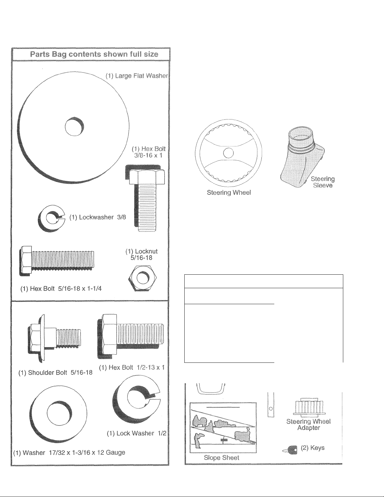
Parts bag contents not sho¥P« f'tlS size
(2) Shoulder Bolts
©
(2) Washers 17/£
X 15/16 X 12 Gaug„
Steering
Wheei
insert
Parts Bag
tj- ' ^ / //
(2) Center-
lock Nuts
k5)
',w \ , .ute
Page 6
ASSEMBLY
has been assembled i
nd proper operation of
as necessary to insure
S RE
wrench
;izes arc
snc
' 'il 1 ' ■'ti.rl ( T w, Ir vt .aerici Ut.liiy brill J
(1) 9/16" wrench Tire pressure gauge
(2) 1/2“ wrenches
I (in 1» i(-fr ’land is mentioned in this manual, it
ht hitid ihi iu'-iji o ^lieel).
/ypfl n - I- — ^ u hi
rlltHlct* f? it
n the operating position (seated
it tighines!
MBLY
r. Siandar
fi'» liijvr ; HAL L jR FROM CARTON
f .^iiTON
ble ioose parts and parts cartons
iic f 11 ti . (be» p ige 5).
Ci iivOic |> Id boroiTi, along lines on all four corners
f i I il'iib .'tid lay panels flat.
» Check for any additional loose parts or cartons and
remove.
3tioii of those parts left unassembled for shipping purpose
:d hardware you assembte must be tightened securely. Us
BEH iRt HOLLING TRACTOR OFF SKID
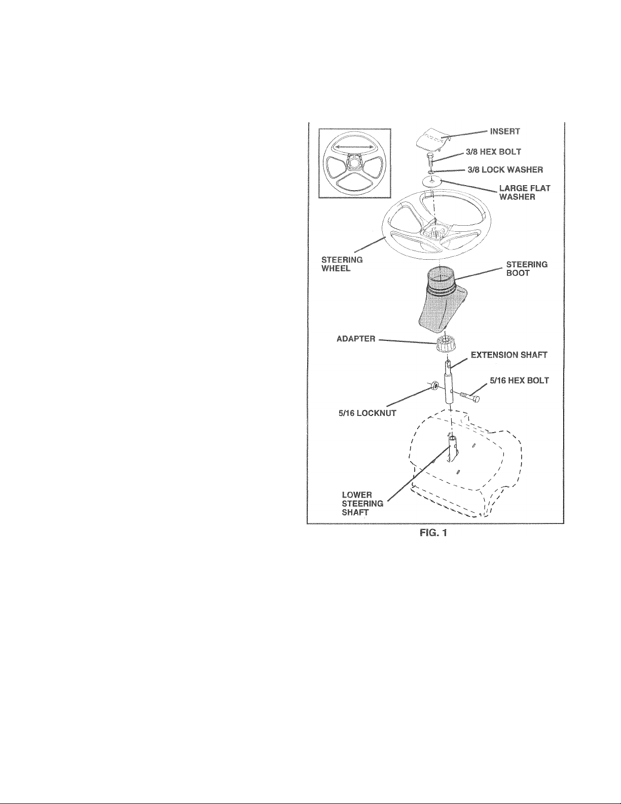
ATlAi T SiEERING WHEEL (See Fig. 1)
ASSEyOLE EXTENSION SHAFT AND BOOT
» Slide- eyfension shaft onto lower steering shaft. Align
mounting holes in extension and lower shafts and
instali S/l6 hex bolt and locknut Tighten securely.
IMPORTANT. TIGHTEN BOLT AND NUT SECURELY TO
18”22 Ff, LBS lORQUE.
• Piete tabs of steering boot over tab slots in dash and
push down to secure.
INSTAl I STFERING WHEEL
» Position Irani wheels of the tractor so they are pointing
siraijiit fonward.
» Cicc steering v/heel adapter onto steering shaft exten-
sicn,
• Frii.-itiuii stening wheel so cross bars are horizontal
(lefc to right) and slide inside boot and onto adapter.
• Assemble large flat washer, 3/8 lock washer, 3/8 hex
bolt and tighten securely.
• Snap steering wheel insert into center of steering
wheel.
• Remove protective materials from tractor hood and
grill.
IMPORTANT: CHECK FOR AND REMOVE ANY STAPLES
IN SKID THAT MAY PUNCTURE TIRES WHERE TRACTOR
IS TO ROLL OFF SKID.
TO ROLL TRACTOR OFF SKID (See Opera
tion section for location and function of controis)
» Press lift lever plunger and raise attachment lift lever to
its highest position.
® Release parking brake by depressing clutch/brake
pedal.
» Place freewheel control in freewheeling position to
disengage transmission (See “TO TRANSPORT” in
the Operation section of this manual).
® Roll tractor forward off skid.
• Remove banding holding discharge guard up against
tractor.
Page 7
ASSEMBLY
HOW TO SET UP YOUR TRACTOR
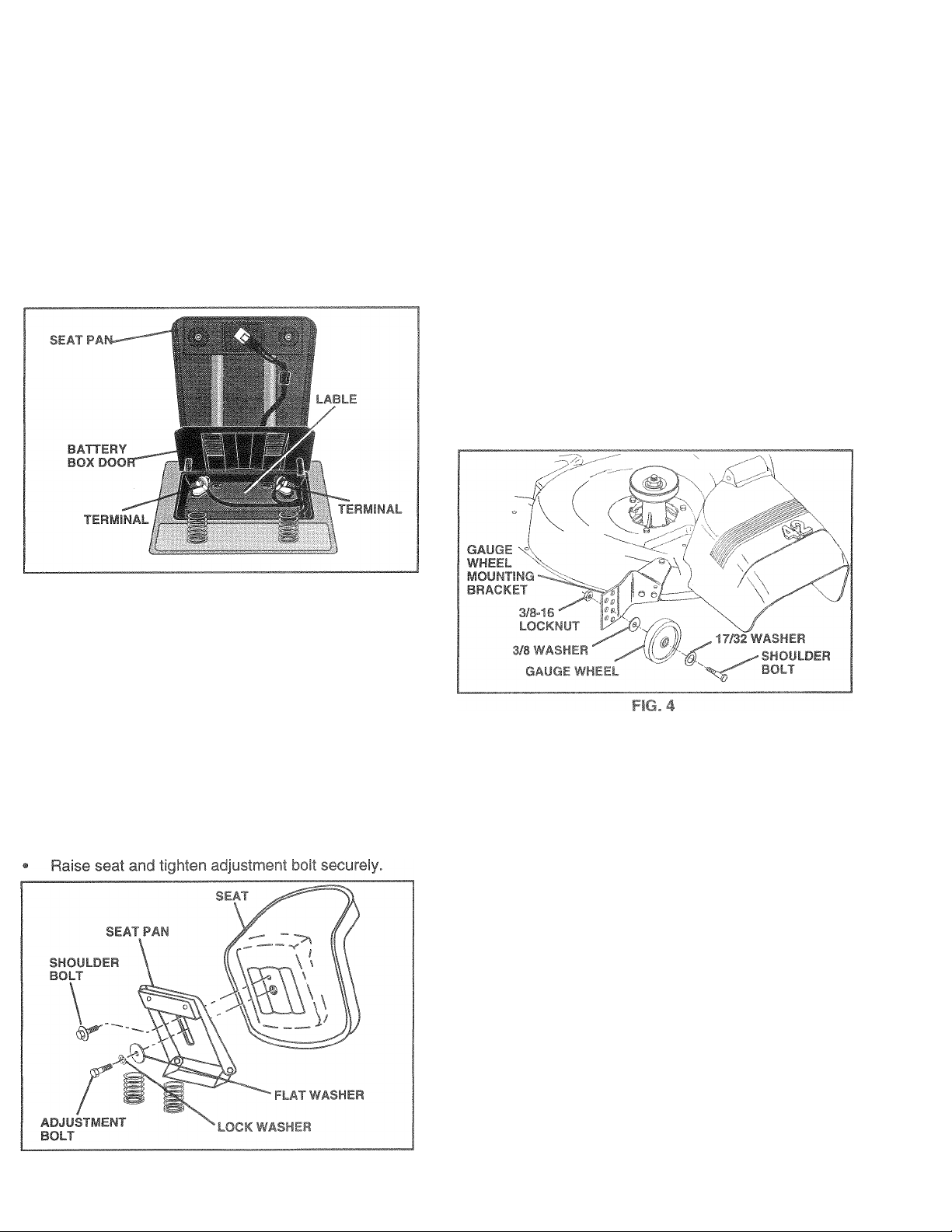
CHECK BATTERY (See Fig. 2)
'jf*- f'3i pan u* 'c ' > f ‘ 'V‘i ^'i ■ i- !■-' / h''
cioor.
“ If t!i‘ L-^tte I ¡1 .4' itii . t , .1 • .'■< I .i c'i!i-50']-/fer.i
inslii.-Ji-il or htt*-' ii ’ '-I I ■( •'-<* i.nyr I] ifrrP'riai*..
ch^o^fc batp.a ff 1 i>ii I'll < ■' ■■ *' '
{Src“BATTLi,('“.nbii 'f.F !3iLiI!F..
spction of this riHri'i-.i’f f ‘ I'ucimn'i;
FIG. 2
TO MOWER
■II
The gauge wheels ar
proper position wher
properly adjusted to c
h I ‘ A t (• , >. i.i'i h I 1 <1 . ,1 m l < t I f v e'
;-;i!('
Ad ju I rni i ;< I i ll < i i nd ■ tiir .g ‘it -H hi I f- ‘|.s A f> Jl •* i F l y J • 'JT sl iL h L in , r .!( ih i jp eic -i io n
section of this manual).
With mower in desired height of cut position, gauge
!,h .Midi ' tdh', a. ,liyhiiyfif(he
gn 'ji'd liO-id'l i. 'I' (» 1.I'll ..ppH p-mt" liuL with
shoulder bolt, 17/32 washer, 3/8 washer, and 3/8-16
k’l hull 1(1 f'(!hi-n '
Ret.f li t-,r .,u! :• >!< nil ! isr.iliih'! fj • ig in
sen If i.jjii'k.if'ik ii ;
ire optimum mower performance.
jp the mower deck in
sr. Be sure they are
INSTALL SEAT (See Fig. 3)
Adjust seat before tightening adjustment bolt.
• Remove cardboard packing on seat pan.
® Place seat on seat pan and assemble shoulder
bolt.Tighten shoulder bolt securely.
• Assemble adjustment bolt, lockwasherand flat washer
loosely. Do not tighten.
• Lower seat into operating position and sit on seat.
• Slide seat until a comfortable position is reached which
allows you to press cluich/brake pedal all the way
down.
• Get off seat without moving its adjusted position.
CHECK TIRE Г
Thetire-s un y- u, if -Ur i i ‘irrl jtr-d at thefactoryfor
shipping puipu. i-s ' i<imii tire ¡»f-s; uio is important for
best CLiitirig реги s сп..! f
• Reduce tire pressure to PSI shown in “PRODUCT
SPECIFICATIONS” on page 3 of this manual.
CHECK СЕСКрГ/LlbT sF
For best! i.fiing'■esij't' т.о"-* Ik ncnimhould be properly
ievele DUSING” in the
Servic nanual.
CHE ON OF ALL
BELTS
See the figures that are shown for replacing motion and
mower blade drive belts in the Service and Adjustments
section of this manual. Verify that the belts are routed
correctly.
RG.3
СНЕСИ
After you learn ha." iu <jp“C.ua .«.jji cactor, check to see
that the bia ks i-'. - oTc-ied. oae ‘TO ADJUST
BRAKE” in fl'c Tsi ,'ге d -.djusunrrts section of this
manual.
Page 8

•' IQT
д r.fmn f
YQU Qp
Ч, tVE WIi
rPERFOf
К RATE AND ENJOY 4EW
jH to assure THA T Yi EI¥E
IMANCE AND SA TiSFAi ЧОМ
llJAi PRODUCT.
PLEASE REVIEW THE FOLLOWING CHECKLIST:
/ -'li ■ f IiT!/ Ilf <-f ITipi-!-I!.
/ I in r< n-'l til'U I '1 t ¡urf‘ in '.игто'!
V Д I 1*''^ ^ c Ib pn~|4' s JiTeiini'i::;! I® iJ (гв1М|1ПиГП
1 (loui ni e ni;''.)
/ ill' iJid-li'ic'Tiii'if it-!« iri'l я|!ге1у.
/ ii; ptiriflal-ii diippinc. nurfidses,
ihf-fl-- ' .M-if i)>'d.4(iML(J li th> fnifiii/)
/ f‘-i UK iiit'Vt-, jf-i'k t pr »рнг1у iFWHi(4j b> side/
i f.'it <'i i- -i! Ini '.nF| (dittincj tp.-ul!' (Tirp rmist be
piupt ifv i fui le,/»-li!iy)
/ CI иД !TK jvp; end drive btitb. Be sure they aie routed
piopi-iij 'irt iMtJ риУеуе eti 1 iiitidc- all belt rcepers.
/ Che!! wiiii,y Гее indt dll connections are stil! secure
and'wifi-' rtie pi -pi riy'-lamped.
/ Beior- -iiiviny imctu! be нле freewheel control is in
driv. t G: : iofl
WHILE LEARNING HOWTO USE YOUR TRACTOR, PA Y
EXTRA AITENTION TO THE FOLLOWING IMPORTANT
ITEMS:
/ Engine oil is at proper level.
/ Fuel tank is filled with fresh, clean, regular unleaded
gasoline.
/ Become familiar with all controls - their location and
function. Operate them before you start the engine.
/ Be sure brake system is in safe operating condition.
/ It is important to purge the transmission before operat
ing your tractor for the first time. Follow proper starting
and transmission purging instructions {See “TO START
ENGINE” and “PURGE TRANSMISSION” in the Op
eration section of this manual).
8
Page 9

These symbols may appear on your tractor or in literature supplied with the product. Learn and understand their meaning.
- +1
BATTERY
CAUTION OR
WARNING
STOP
I
I
REVERSE FORWARD FAST
i ' It'- '"'I
©
ENGINE ON ENGINE OFF OIL PRESSURE CLUTCH LIGHTS ON
OVER TEMP
® l\l ^ # -i'
CHOKE MOWER HEIGHT DIFFERENTIAL P/
LOCK
1-
UNLOCKED
SLOW
LIGHT
I R N H te»|I
REVERSE NEUTRAL HIGH
MOWER LIFT
m
ATTACHMENT ATTACHMENT
CLUTCH ENGAGED CLUTCH DISENGAGED
DANGER, KEEP HANDS AND FEET AWAY
«
LOW
KEEP AREA CLEAR SLOPE HAZARDS
(SEE SAFETY RULES SECTION)
IGNITION
PARKING BRAKE
FREE WHEEL
(Automatic Models only)
Page 10
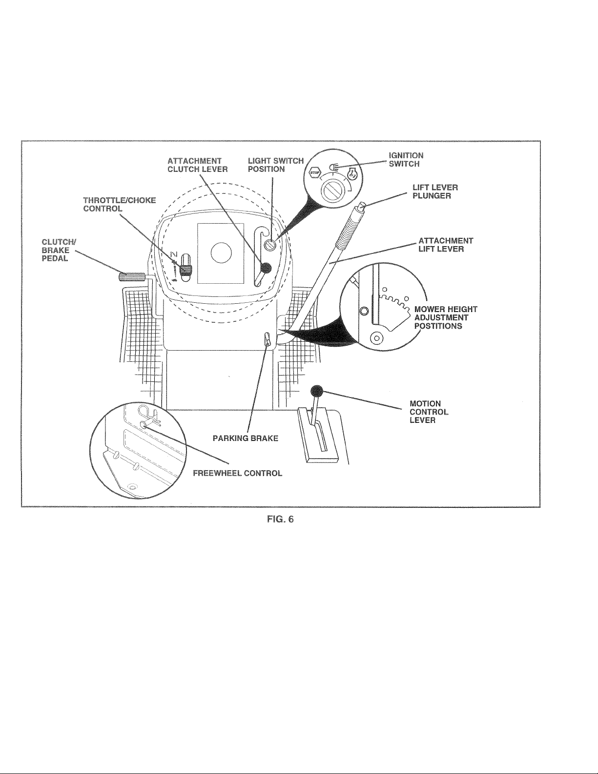
OPERATION
KNOW
F. r-fS OWNER'S MANUAL AK[i FifLES BEFORE OPERATINCi YOP^* U-R
Compare the illustrations with your tractor to familiarize yourself with the locations of various controls and adjustments. Save
this manual for future reference.
Our tractors conform to the safety standards of the American National Standards Institute.
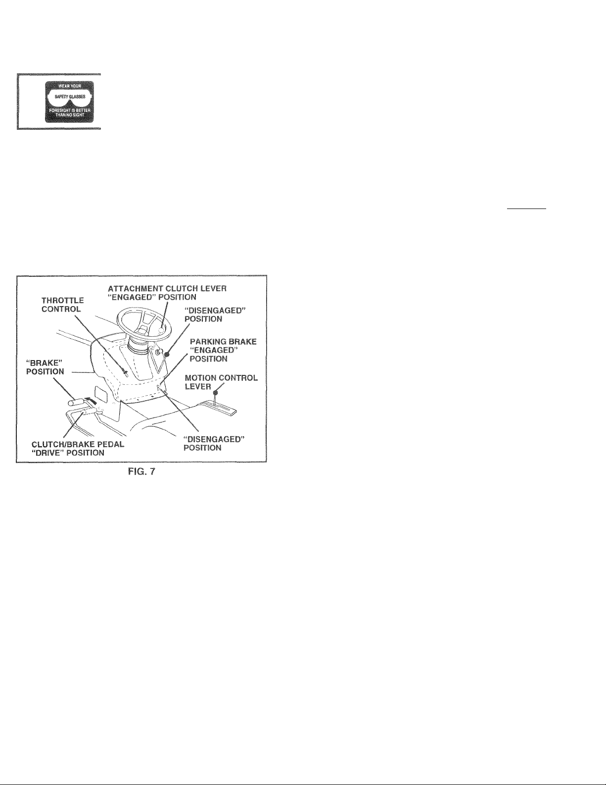
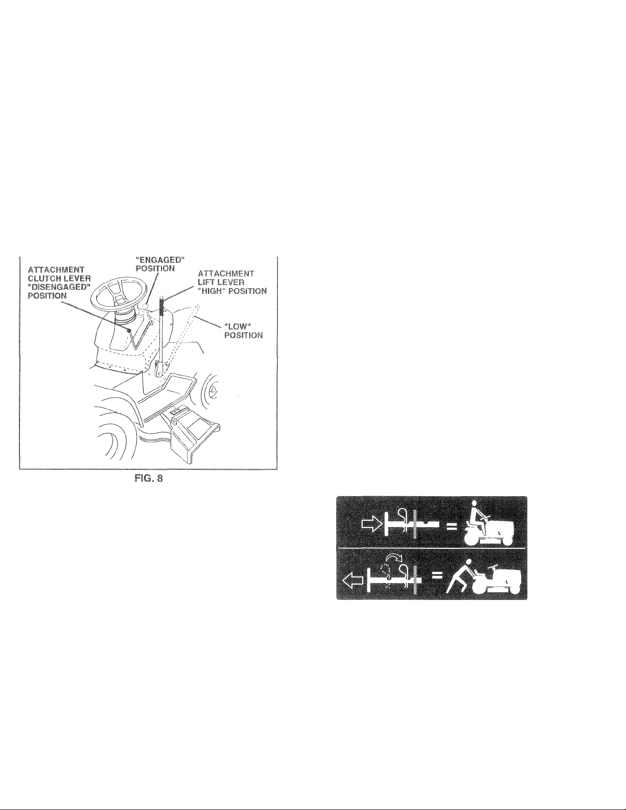
ATTACHMENT CLUTCH LEVER: Used to engage the
mower blades, or other attachments mounted to your
tractor.
LIGHT SWITCH: Turns the headlights on and off.
THROTTLBCHOKE CONTROL - Used for starting and
controlling engine speed.
CLUTCH/BRAKE f EDAL: Used for declutching and
braking the tractor and starting the engine.
P*-RKING BRAKE: Locks clutch/brake pedal into the
brake position.
MOTION CONTROL LEVER:
direction of tractor.
ATTACHMENT LIFT LEVER - Used to raise and lower the
mower deck or other attachments mounted to your tractor.
LIFT LEVER PLUNGER: Used to release attachment lift
lever when changing its position.
IGNITION SWITCH: Used for starting and stopping the
engine.
FREEWHEEL CONTROL - Disengages transmission for
pushing or slowly towing the tractor with the engine off.
Selects the speed and
10
Page 11
>■ fí'FRAI'f-
HO^T^ySfc
The open
result in í
your trac
safety ms
3k over
If tractor can r
e damage. Alw
rforming any a
»pectacies or s
TO SET PAR^iNCi BR5PE iV'r- Fiy
'YL!UrtrariOili>=^tjUlppt (J »i-ilh . in,,( t ¡..j| - ir ■- /-I|,inc!
'■-vrifch Wher p>nnini ■' ru• i-.t'i.ft tj iIh
operatot to leave the _« J vaUir.iii tit a .vitni.j fti- p-irMrig
brake will t>huf ofi thn «nuii.i.
• DepresM iutt pr-j i i v|E po'-muii
and hold.
• Place-path n>i hickc k /»a in Lfj>-AFt F*'p" it'ori and
teleasepre3&ijrefrorn'‘lutch/t.re*'f pf dil PedaRhould
remain in‘BRAKF pOim .n l-N-f ii't p-irFinn brake
wil! hold iratior cecuro
suit
ays we!
qn
ill
№hi
opi rating
djustments or
tandard safety
!MPOR
POSIT!
BATTE RYTC) BE DISl 3HARC3ED
HOTF '
>i< i/'ltf
cause ‘
-il Wrjf sto
TA NT: LEAVIt JG THE
j f
lot
)THER ■
; Il
;r certain
id€
ith
> ‘Usl b Í 1 If *fling, h
& 0
hr.
....
ingine wh
■P€
i Ciifet f i( irfoi turn
A
U M 'ÍK )> I ' ¡.<4 ll‘ I W ‘ * 'Pty
'¡I Ì. ► t I
“ 1 o
N11
1CiN SWITCH f IN ANY
™ .
FHAN '*OF
ions wt ler1 tractor is 't snding
conditi
otei
jrass. '
len stoi
....
pptr
/ILL. CAU.
AO).
Í C)E,
rigii
le - hrt I'iiqdses mj'/
11». 5 r . f iGf
ig ti
Tor on gras
TOOSETHKO.fl ( er. rig. 7)
Afwavj Oil«-*' vfiio'-« I in I ihn .Lli
• Optrs'iiiy' Qiiif i F !, «I. I!i|i throttle reduces ihe
bjti-ry vgínt
• Full rhfuff.f oifci'if. L ,L ' . o and I ¡rower perfor
mance,
TO Mt'VK FiL' ..i ,.t\WARD
(See Fifj 0
The direction and . pei i of movement is controlled by the
motion contrc
• Start tractor with motion control lever in neutra! (N)
position.
• Release parking brake and ciutch/brake pedal.
® Slowly move mritrol lever to desired position.
iision
SE THE
ir.llltv
STOPPING (See Fig. 7)
MOWER BLADES -
• T0 stop mower blades,move attachment clutch lever to
“DISENGAGED” position.
GROUND DRIVE -
• To stop ground drive, depress ciutch/brake pedal into
full “BRAKE” position.
• Move motion control lever to neutral (N) position.
IMPORTANT: THE MOTION CONTROL LEVER DOES
NOT RETURN TO NEUTRAL (N) POSITION WHEN THE
CLUTCH/BRAKE PEDAL IS DEPRESSED.
ENGINE "
• Move throttle control to slow position.
NOTE: Failure to move throttle control to slow position and
allowing engine to idle before stopping may cause engine
to “bacWire”.
• Turn ignition key to “OFF” position and remove key.
Always remove key when leaving tractor to prevent
unauthorized use.
• Never use choke to stop engine.
TO ADJUST MfV.iihF CUTTING HEIGHT
(See Fig. 6)
The position of the attachment lift lever determines the
cutting height.
• Grasp lift lever.
• Press plunger with thumb and move lever to desired
position.
The cutting height range is approximately 1-1/2 to 4". The
heights are measured from the ground to the blade tip with
the engine not running. These heights are approximate
and may vary depending upon soil conditions, height of
grass and types of grass being mowed.
• The average lawn should be cut tc
inches during the cool season e ver 3 inches
during hot months. For healthie etter looking
lawns, mow often and after mode
• For best cutting performance, grass over 6 inches in
height should be mowed twice. Make the first cut
relatively high; the second to desired height.
.....
imately2-1/2
____
^.owth.
11
Page 12
1
ЭРЕ1ЧАТЕ 110 WEI Ч (See Fi
г is eouippec
Iractoi
/ attempt by
IQin© i
running and the attachriiGni c
"%ff fhp
J with
' the c
jht of
mower with"
OWGr i
lower blade
attaci
!S by
ontrol.
1 В1Д,DES ™ dise
luich c ') It C 1
«.'bilifOH |if> o;»t><< к j
hitPjiJ|e-bi|.^'-.ht _ fit|,v .jr . -i r -, I
i^rs .4 «qiiiir.p- I <‘E !i -, .¡p |
A
y’JéE S к |.|а'.Г f
anoperatoi r prese
9- 8)
dutch f
cu!\
hmeni iif! о
engsging
ontrol,
attach
ngage nment
HILL
IN: Do not drive up or d
:h_slopes greater than 15°
A ГпоТ!
Ifive across sny slope.
est speed before starting up
Avoid stopping 0
f changing speed on hills.
If slowing is nec<sssary, move throttle control
If stopping is abs
lOt.-k' .<- - - ' / L )M> |-|'ll'
pedal quickly to brake position and engage
brake,
I>'|‘ •- , ' f «V ii ",il I / >k n-rl-t!-I |i 1| p Ilr<r>
• u ( '-t! I •! i*'i, > t ,t I, t ‘ 'I I i Fit ), L f V bh I ' a
f'f r r ' I ■ I ! ' > PM 11 (I - I ' K li 'PHi 11 rpE
ill!' ,l f MM- i/>i ! m ! Ht ,M •
(. 't a., „vp',,. \ I'>wv!y ¡'Jp^ ep'iMnq'-t-i. H, j.d
ciutch/brake pedai.
I .'pi > i • ,■ ill-,'r-fi "G, frr I !. vr I M-It >p( sf M d.iig
H;| .(< t ' Ill'll I' tJ'l'/
r F:qs. 9 ahrl F, I
j « ir-y vf-Hi il Mil ba-me tiiiHi'-ng ine
hai! nil I ,iM>/t'i'-('II i b'Oi.iK.i ir. iipf'Wbt t iiiig
POMi Ti r >«' r ' • f ontiu! I Mi.f iM'i at the (^a' dravi/har
, T irm It
• Raise attachment lift to highest position with attach
ment lift control.
• Pull freewheel control knob out and hold in position by
inserting retainer spring into forward hole of control
rod.
• Do not push or tow tractor at more than two (2) MPH.
® To reengage transmission, reverse above procedure.
NOTE: To protect hood from damage when transporting
your tractor on a truck or a trailer, be sure hood is closed
and secured to tractor. Use an appropriate means of tying
hood to tractor (rope, cord, etc.)!
FT
FIG. 9
Page 13

OPERATIO^
i m t"' ?! H’H í'frH' >* ’jf. I t - " f
• Th6 Giipins in yourtrsctor ll3S b<
fáctory, slrssdy fif©d with sumiT
.1 i |.(- i jifi, , j| > -f.1 , ,,
*' (',» lll>j\V, f.(< f H (' h n I • .
rÍ!pollf I cu lu lïrüü ^ i! li s’ I U I t' \ %'h!* J
rcFioc- w-d r‘-'lí f-,* I /' ! il i!i ' ■ ' 'I ' iMir.íii
f Uü rnaw ,r .>1^ :ii i w' r,- ^ ,ir:
® For luid wGoth«"'(f.‘rjiiiiM mo i L> o • <y> hií . .f
easf-i ùïartinq (de- 'w!l VL/ • i i / i-l HÎ ’ ii. Ihe
oU'Jorpe'Rp"pf>noiDÍiii‘. f"f|,,r, m; í| I rn-nurl)
* Ce cfidiigo » fi©,ny olí "f- tíir-' ii 4i.»i,ibili-
íieo secfon in (hi* aunU'’!
ADD GASOLINE
• Fill fuël tank. Use ire.-h, i'lf.oíi iegula' ui .leaded
gasoline with o mininujin uf 8 / octane (Use of leade J
gasoline will increase caibori and lead oxide deposits
and reduce valve life). Do not r t‘k oii w ith gasoline.
Purchase fuel in quani’ties that can be used within 20
days to assure fuel freshness
IMPORTANT: WHEN OPERATING IN TEMPERATURES
BELOW 32“F(0°C), USE FRESH, CLEAN WINTER GRADE
GASOLINE TO HELP INSURE GOOD COLD WEATHER
STARTING.
WARNING: Experience indicates that alcohol blended
fuels (called gasohol or using ethanol or methanol) can
attract moisture which leads to separation and formation of
acids during storage. Acidic gas can damage the fuel
system of an engine while in storage. To avoid engine
problems, the fuel system should be emptied before storage of 30 days or longer. Drain the gas tank, start the
engine and let it run until the fuel lines and carburetor are
empty. Use fresh fuel next season. See Storage instruc
tions for additional information. Never use engine or
carburetor cleaner products in the fuel tank or permanent
damage may occur.
CAUTION: Fill to bottom of ças tank;
filier neck. Do notoverflil. Wipe off any
spilled oil or fyel. Do not store spill or
A
use gasoline near an open fieme.
F
J ff 1©
I qrounci.
:tean, rsinsertíhe
•iq.
qin
TU€
Oil on seat in c
51TIC
pedal and set
Place motion c
N1ov0 êittHchiTï
® Move throttle c
NOIE r
Ü I ' ‘ ,1 (, I ■ .1 fi’h 1,1 .iti'j>I
ns tliV Í, h O >r ! I I . > .rU (J-'OtlOr,.
)ntro! to choke position.
ii.‘ .< .• 11 f I fiI i!I Î ' ( !■ ! ' i,'fiiriy
procedures oeiow.
• Insert key into ignition and turn key clockwise to “START”
pi" iti> !|(! i‘ !■ 1 i ' . iti < ► fiU’ii ! Do
m it r-j!' t, li I I i! ill! II' D A f III. I! if ’I fii-Lor f
f»hO p( t iiifKf K i.qn. di ' ivA ; I »rt .^itsrt
fevei j' ittf-Pii.! fi ' ifir..;t!i .«.»'Lit j''> ipo‘^itifiii,
U3P •*> V r. It.m Mill/ <i i I'MMiiit MillfSi O'not
at irt mi'Vt «>•( ih.Mil ■ f tilr I r ■ k fi fh^ choke
pt nHl ii-il
WAnMyCArUff "MUik,/ iac.i'»
• Wfitta ii.jfii .1.1 • I ( ifCr .'icifteiriSt
p,j itl. 11
e I!l'--'ii l t-.ill 1" ( , I r|f<vvn(- IKi-.j If
(ht ‘ iiyr- df*i-‘ Ml, -[/! h -id r«-=f rrftnr t-ngine
.irdd’i' I'lit,,! i li iiiKi. f-U'iiiiitti»-chokf
a 1 dl Mt r| ,
COLD Vvf/-' hi n I/ fl'T .'ri ,-iidbeloWj
• WTf noinir.e d.'ih ji! M/! i«vio foiun With the thfottie
(orii.ul in !fi( >' |¡'^г• rntii ftt engine runs
r jiiuh'' tl' ri c.i. r,i >ii|t rli tij.Mitiun Thi-,
h'. / r quir« it. iv it I I p DOfiod fi cm several
txMid If i* hi. MM • |ii-ii>1irig <1. flit teni-
J<-t it'itl
AUTUMA ¡1 U /■ h V, k ■' I i <P
• Bi foil i.rf.rqi! Kill 111 '.j iii,M ih( ironsmis-
' oil 1 . I up I ill- »
• Be sure the tractor is on level ground.
* Place the motion control lever in neutral.
r, i< , t| f ,M« ,1, - I ' i(U< h[.' h'Fp/hrake
.( f'A c m ft ■ U r> n
s OIL. J f, 1 .IIUH ' <I . tr ii I It, tc Aatt.. up.
This can be done during the engine warm up
period.
• Tlie atk'chrrienU c / n arso be bsed during the engine
«3iT-.f osrri’ I ii- -an 'ii.r'V'I bar been wormed
up.
NOTE: If at a high altitude (above 3000 feet) or in cold
temperatures (below 32 F) the carburetor fuel mixture may
need to be adjusted for best engine performance. See ‘TO
ADJUST CARBURETOR'' ii'i the Service and Adjustments
section of this manoai.
utch/brske
13
Page 14
р'Г.Т'АГИ. tr;
PURGE IMI
li: 111
»nsun8 pri
menided1:hat the tr
:or to
trad
trapj
ped s
j dur
opei
IMP)OñT JWT
REMOV/
SHC)ULC
open
зрета!юп arid
ansmission bie purged befc
r thi
5 first time. This procedure wiill
lir in 4^ 1 li ill ii.,- i
ing Í
shippiing of your traicior.
4 ' "iiLli f TF. • OYL .. ICЛ- ВЫ.4 IR'
\L I
FOR SERVICE C
) 'b
JRGED AFT ER REINS
BEFORE OP:ERA! ING THE TR,
Placestraidor S;afely on level í
h Trki
ng t
set.
Lrf'i'j ;r II, iHtiii'.-, 4M>^ |4i. inq iiF-f /ftiH-l ubtroi
ill fifелЬс-rii'iQ |:r,vit'on q'> ^ Tf' ТР«'П~Р'~'Н * ’ :n
t^llf P''tr.n 1 iT(iflU?''ll
® I sedt ^trtengiiit Afiertht fjngine
, luntiilH 'П tde rhr'itlP <,>r.tri.i to alow pO>ltijn Wilh
•»»tier, I iii.iol '“v'tr и I cUiral (M) pfritsor, -Lwly
‘ Ihic h'hral-p
f~iL . riris'snn '"rrifrnl If i-crfr, rnh i rnH
i I Id fo! iwi- (Ы 'Ы Of ids Move к vh to full !е\-^'?е
pi i-it.s.ti fii.id for ffi- iPt und- R'-pf-as this
proo5»dur. throf (di tini-'»
MOTP' t<ut!! g'hit piocoouff ttm ¥i|iDenortiOd meiitof
dri/i *ht fl" ' he iiri; beirifj'*,ni -^d rcm hydnulic drive
system.
• Move motion control lever to neutral (N) position. Shut-
ihite
performanc Í, It IS n
0СОГП“
)ге opecrating
remos any
» S hi III-!
t haved©¥0l"
)R REPLA C L Í ' !T, IT
» - Ì. /Р
Г ALLA
surface with ngine c
TION
if <nd
ilOWINI
• Tirecha
I f (M lU..
i' It' ’ '/ n< t I'ppiritjS i .j=* hoKjeo a dr th,.
iti'tl'i, l-'-fMiii Hav-^fhe t I’i nieatothe riqt.tof ihn
Y ,< I .• , r,i will
IP
)UlC
jrC
a Adjustments
side of mower
. 1 1 1
r-ote Fi/en di^ttib'fEinn el
-E'
' ho
eled for bes
^OWER HOI
action of this
)uld b¡ Us
t mowing
JSING’dn
J t'ji IM II-
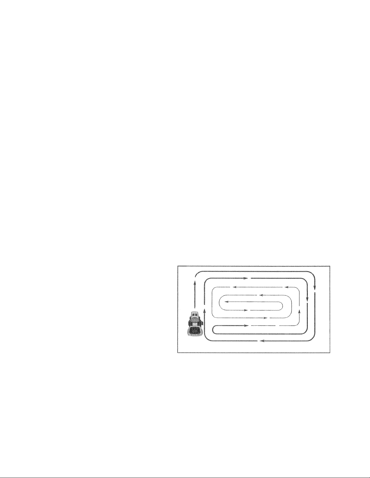
lipf. fi I mil) ins»- l•rllfOfГ^^ r Httihd
'/.It II r.I x'i"i' II(j( ir m Tan b/ luir, ng s' (h*- nght
• di 4 will irchaifie from «-hrubi
, dnv< 'f »y- lit t'lR'-or'p ut Iwo irurido mow
i<i 4i ' ppj‘i|t_ diieaiOh inatiii.j left hano lunm until
e I iL! 10)
It q'i' ' i: L 4i' «iiely tall 4 "hr uk< bt fnow"- a twice to
red jce I rad and possible fre hazaid frem dntd clippii.ijj Make firG f'jt relatively nigh the second to the
deciteri heighi
U' ■ not inow grd'S when it is wet Wei glass will plug
rnower and Itavs- undesirable clumps Allow grass to
dr/ befijie mowing
Aiwa/c opeijfs fiigine ai lull jinoaie wnen mowing lo
oire bettei mowing performanrt and proper dis
(riciye of ifHteiHl Reguldto giound ipetd by seleu
iny 1 low enough gear to give the rnewer cutting
ptuumiarv e is well as the quality of cut desiied
VVhti* operating attachments select a gtound apeed
that will cut the teiiain and give best performance of
the attachment being used.
manual.
Engage transmission by placing freewheel control in
Sitting in lh< tri! to: seat, •'t i/»ngir,t. Aftc ■ tr.. ngine
S lU irinr ri I It ihrrr'jp r.inirof+o half (ISj ^peed.
Witli riv t!L,i! ■ ,r tru! .e/t * n neutral (I i> ¡Xn (ii n slowly
fJi. cngaoe > !UP e/liiakt p» ti-i
•lowly nio'-f r-K itf- . i oriti .1 k li I forv/.i ij niter the
t>'.‘f,r r ic--,, X pi-vo-xir „iol, five Ri poi, 'tv.iymove
ro'.fii f i-'» r t( |. tpit I the
•t V f MtiVf; ppro. iifwtriy ‘i/c (5) ft
is'>ii'>ipo>.iiuoilsvci to 1 t Hr Mii I ij ij po; iiLh Rt peat
thi. pr- ttilu:i v/ith ths niotirn siitrtroi k vr i ,hree (3)
' - 1
eturn the
times.
Your tractor is now purged and now ready for normal
operation.
Page 15
i" í; F'íf-''NPrU:J
IF
4 Repía^e blade; incre often ' fTi >/'snj in andy *il
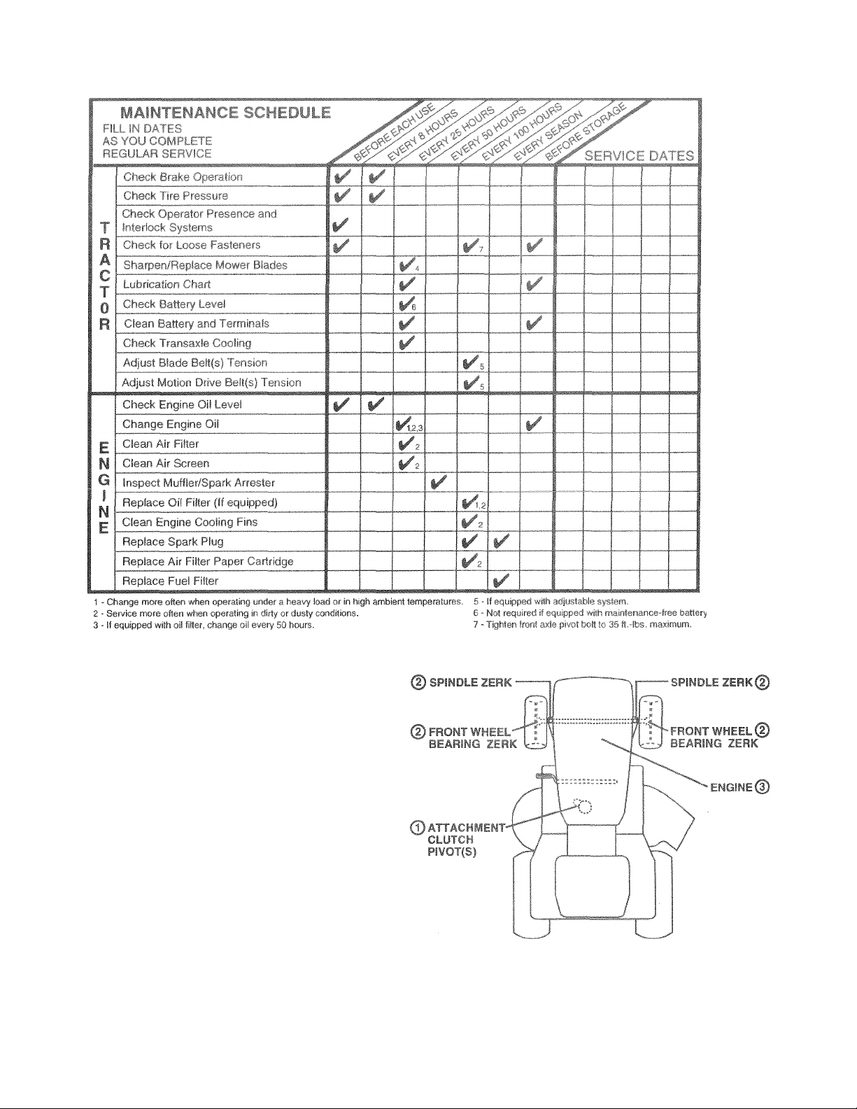
GENERAL RECOMMENDAI IONS
The warranty on this tractor does not to^/er items that have
been subjected to operator abuse or negligence. To
receive fuli value from the wo rraniy, operator must maintain
tractor as instructed iri this rnanual.
Some adjustments will need to be made periodically to
properly maintain your tractor.
All adjustments in the Service and Adjustments section of
this manual should be checked at least once each season.
• Once a year you should replace the spark plug, clean
or replace air filter, and check blades and belts for
wear. A new spark plug and clean air filter assure
proper air-fuel mixture and help your engine run better
and last longer.
BEFORE EACH USE
• Check engine oil level.
• Check brake operation.
• Check tire pressure.
• Check operator presence and
interlock systems tor proper operation.
• Check tor loose fasteners.
Do hit <■ .’jh ..
LUBRICATION CHART
0SAE- r. i ‘
djREFERlO W-fi
iMPCRT*..‘i- f . I I . •< . F fHL r -m,! POINTS
WH Cri H WF or ito i> ' b 3E -vi H k f . \ IF C ,.US LUBRI
CANTS WILL n ll ; ■ m , Dll-l HST All L SHORTEN
THE UFF r-f iH- • r ■ ' '‘'F°!W KNC. BFARINfiS. IF YOU
DERED GRAPHITE TYPE LUBRICANT SPARINGLY.
OIL
‘ SNl-iNt" SECTION
15
RY, POW
Page 16

TRACTOR
AIvtfays observe safety rules when performing any mainte-
ir'hsri.vi:;,.
If tract
or rc
iquires more than si)< (6) f(3et StopF
ispe ed in hi'/* 1 t (j- 1
at high
(See ‘ ADJUS 1 • i
ments
TIRE
tion of 1P 1.
o
• M.âintclin propler air presisure in c
3J £SPECIFICATIONS
U(
® Kc
septir©s frete of gasolirle, oil, or insec
ti
hidi ca n harm rut )ber.
ils W
» A\/Old stumps stones, tdec
otiher f
lazards5 that may
fJÎMΓf. 1 0seal tir <turi:ium ind pi
si ni'*
peri' 1
, tire se
jaks
•alant may be
dealtsr. Tire fcdidhi isc, pieL tire
, th¡en bréikem lUSt be"a
!'■
n the Sorv
ll).
•1 t|r
in pag0 3 0f this manual).
!” C
3, shsrp
sp rut!
(lî
e darusep.
e.'eni
n iff kdmv
corrosion.
OPr.R/' K?F] REiJC r
ni ‘ ux-* .. r H>' ;i,(! lilt itui ! sJituii' are
w< <hnq piftjt'lv if yt>ui does not mnctn-n as
•Jesunr-i !i j. 1 >f.t pri t'i-II. .t.untdMifiy
" Fnf rrniri- h-jij!Jiut tan unie- ihe nlutrhRrake
poci'iisfi liui*i.prv''‘^“d tlbitmcnem-Oillutchcontrol
IS in ifio d -Mid iqed [Mwiiioii.
' ’.i'lhr, d>< t-nginr I funniiio ..nvattf^miiibytheopera-
toi ir IfriVfc ihc Xf'ai Without iirst ‘ettiru the orrking
brak : houl.. hot off ihe or-yine
' Whf nttif r^npiriF k runni !<j sndtnr Litiarhmentdutch
IS en .o |i-d If i tempt by the oper.-io 1o leave the
■^eai h ail i 'hue off the < nqne
* The att3chm(=n!cl<Jich should never operate unless the
oper tor is ir, the "^eat.
)ino *distance
idjusted.
ice and Adjust-
is(:
See “PROD-
)t CiDntrcll chemi-
Obj€;cts and
! tim
ifla
- due n
'fr„im ycijf itKal
dry
rut and
FIG. 11
TO SHARPEN BLADE (See Fig. 12)
NOTE: We do not recommend sharpening blade - but if you
do, be sure the blade is balanced.
Care should be taken to keep the blade balanced. An
unbalanced blade will cause excessive vibration and even
tual damage to mower and engine.
• The blade can be sharpened with a file or on a grinding
wheel. Do not attempt to sharpen while on the mower.
• To check blade balance, you will need a 5/8" diameter
steel bolt, pin, or a cone balancer. (When using a cone
balancer, follow the instructions supplied with bal
ancer).
• Slide blade on to an unthreaded portion of the steel bolt
or pin and hold the bolt or pin parallel with the ground.
If blade is balanced, it should remain in a horizontal
position. If either end of the blade moves downward,
sharpen the heavy end until the blade is balanced.
NOTE: Do not use a nail for balancing blade. The lobes of
the center hole may appear to be centered, but are not.
BLiiDE LAn t
Foi h t . V ijit ioifwer bladr's must be kept sharp. Re-
piar < hr*:f nr dam; g.- (, blades.
PLdEr ftEMCVAL (See Fig. 11)
Raise rriuvrer 'o higliesi position to allow access to
blades.
* Remove hex bolt, lockwasherand flatwashersecuring
blade.
• install new or resharpened blade with trailing edge up
towards deck as shown.
IMPORTANT: TO ENSURE PROPER ASSEMBLY,
CENTER HOLE IN BLADE MUST ALIGN WITH STAR ON
MANDREL ASSEMBLY.
® Reassemble hex bolt, lock washer and flat washer in
exact order as shown.
• Tighten bolt securely (27-35 Ft. Lbs. torque).
IMPORTANT: BLADE BOLT IS GRADE 8 HEATTREATED.
16
Page 17

^1
BATTERY
Your tractor has a battery charging system which is suffi
cient for normal use. However, periodic charging of the
1 th ' • V (! I .
.
............
I • !.;■ I<! > u' Ml
• Keep battery and terminals clean.
• Keep battery bolts tight.
» hr«-f m I’l 'f n( 'if.Ml
o >-,f ''har^t >i - ■>'» r ' . ' hi ' i
iru iPAfJ B.<-l iTi-i erJM fi HMlw n
Cornsior. and din r.|i tht -01^1111111:1 ts cause
tfie bdPery to liah p*
® Open li ittew i j> 'I'lOr
• [*Fc onnect bLKO I. bYtuy r;jrj|-t,r i iht n HI hi bai
ter/ cable -arid r-=tTi'*Vi-" batten» frort» lii«ctor
• Hinsn the buimfy wtm v.. O, an* dry
• ClferfOteriiiiiwI^ arifihitic.yr jpOi i,d with witebrush
until bright,
• Goat teriTiiridL with gnast ui | ermleuni jelly
• Reinstall battery (Sefe‘hEf Lot IfJ.-i BATTERY" in the
SERVICE and'ADJlIMMLilTS ection of this
manual).
V-BELTS
Checf* V-be!is for deterioration and afierfOO hours oi
operation and replace it nerc'^barv The belts are not
adjustable. Replace belts if tnr^y begin to slip from wear
TRANSAXLE COOLING
The fan and cooling fins 01 transmission should be kept
clean to assure proper cooling.
Do not attempt to clean fan or transmission while engine is
running or while the transmission is hot.
• Inspect cooling fan to be sure fan blades are intact and
clean.
• inspect cooling fins for dirt, grass clippings and other
materials. To prevent damage to seals, do not use
compressed air or high pressure sprayer to clean
cooling fins.
i ¥ UHAUcis
I TEMPERATUHEI
—...........................................................................
'll S I I f -f !•' n_ I E I i|tn -L,
.............
NOTE: Although fTiulti-viscosity oils (5W30, 10W30 etc.)
IÍT|¡.' t - ..l ‘i.l f, ul‘j -“„.iil Í J ITiiJfl I iH
will r • >!' iU , I (' Í t H.ilf.J -M
*>, I h-Í t ii,| • I, fill, .1,11, /» i i.ji... f. (j ( hiiK to 'ii'uld
[" 1 li ' liuilif 1 I. V- II I'll to. nil.., I il 11 r.il
fhi'.f.-ih hI . Í 1 .. . ■ 'liptljt'Mi .laíK<0
J
ii ■’! li i ! O' Vi*
once a year if the tractor is not used for 25 hours in one year.
i he i VI»- liM'i' r ill. ‘ill *(t»e woiii'j 111*-^i.qirii"
f.nu ifiM t( i<|h* L I h'>. .}>< 1 n.oFi h jhtpfi ul fil;
cap/dii'-irl ■' Hi'I » ihhrti . !• . hwr ti.c »¡IKnel.
TOrHAHiT L!jr ;ri»_ ■ Í 1 ..-f 1-. , ' j
Detc-iininH Ktiip.' All . i'£v . «pi-iíoíiti*:í!oiti*i'eriaiige.
AllciIrTii! i-fiMi/r u. I] lik atioii :L Tm h 5H.
• Be " iirr It i> t. ' 1 '/i. Sf. ~i 1! »
» III >AÍíl 'Jf 1111 it,' li it* -I ' 1' I , III
® r.jt* Í' (>li ÜI ' ' i'lMhl. ff lit !l!
» H' r'M Ih|f! ‘ ti [' p, • f*jl n o ÍO 1IL. vdirt
to enh r fht. I ii'iiní wneii c t ;ii ling oil
• Remove drain plug.
• efin r.*i has droiii-(f»•'■oipli 1'iy rofl-meoli i rein plug
Olid I'qhtr-ii sM ctriv
• R'd.ll-riLi'iL w:t'-f II th! uo'i ,I I'll dipstick tube. Pour
* lo'Aly Oo iiot .Mf ifill I . ■ f ».(oximate capacity see
■PriüüLlCT ■ f f. IFiCAfiC-tv‘'r on. page 3 of this
m. !iu I
® Usf fi'i! 1« <■ •oi> filie If viiii Í Mor checking level. Be
surt^Mf 1, t , rf, ,s [il hf. . I ecurely for accurate
rerdinq h» -p t ¡1 I ‘HJl 1 lifv on dipstick.
TRANSAXLE PUWP FLUID
The transaxie was sealed at the factory and fluid mainte
nance is not required for the life of the transaxie. Should the
transaxle ever leak or require servicing, contact your near
est authorized service center/department.
ENGINE
LUBRiCATION
Only use high quality detergent oi! rated with API service
classification SF, SG, or SH. Select the oil’s SAE viscosity
grade according to your expected operating temperature.
17
Page 18

é\
jpe
ifinage
nours 01 operaiion or every s<
Service air cleaner more often under dus
)fi
llene
jition
* Remove knob(s) sno cover.
TO SERVICE PRE-CLEANER
‘ 1 r- 1'' i pi 1“ -I, , . Il .
* ‘V t E il II KjlJli' f.( If-.PF >,1 r>f-1 -‘I t. f
® Squeeze it dry in a clean doth.
" ' niiraf .1 || ■!' I ■» I!-,
ít ih orbenl
'"T "i I ¡1* ' t k p t / e -I I 0
** '■> y «>t I J 'ill IJi I ¡1 pi ' I pi
aner.
> f s ir< .i A ! ^ ' I* I-! f'»« ' i
lit if t til <>i'- > sneJ secure with knob(s).
TO ,IO’v‘i' ^ ( "MniOi t
*> Brria'r 'Kridyf I lilt
® < Mull/kit''f . aniidy-k, ,)r-M II, tirbris from en-
f. r.r*j • rhiii,_tfir I Ifc.-in Lj:--' cartfuiiy to prevent
d Ipi . i(k fi'iq ‘.aiPbirti i
« ( luai), _ri!i‘<ie rwi^ppiri jQHitiyuniOi. urface. Ifvery
• iihy o' dauirtOi (I rep!; i o «' kTiidijt
» Ri t < 1! ( uitfirffj- nui preiiiatier o'lvr r and secure
will! ill luoisj.
IWrOPiAN* F>i~rPOLri.M ''Ol VPrn - SUCH AS
KEPO^'LUL ARE HOT TO [^F USED Tu CLEAN THE
C/T iRiC'iiL. i t MAY LA J: L DE’“FRICRATION OF
THF I HTR’DCE. Do. H H jIl MEIRIDCE. DO NOT
US'" PME , liROFFl Air. 1 k riEAU OR DRY
CAF THiiOF
■i . Ad I I F-*!; F fi F o ‘ s 5
n must be
imaqe frorr
dirt i tubborn dried gun
fiberi
iMt ' t i'^d iilii I' "O- Fttj f 0}
Reno., miy >1i't .'iit or >>!l fr'-r. -noinr rooSin tinsio
prevent engir
|. ÍI .^fpI I tr^r-z^dt’ i.>
I Pi< rri'"'-- « fcw- 'tom blotvet rou^sing ¿rii! 'ift hou; irig
a 1 ! *i|0 ti Í I'J.'fc .-iveinfilv .Jit ■ I'uii'ie
<,i.ivr of! ilii (.yt-ninq ic tjntr/ of «dti
11 rnum'ro ) 01! i t *tiff bri tío bfu Ji t dhurouLihl/
I L-1!« eri'j'! fc 'Gdini| tin*
• ti ffc..' cOifM n-'f rsfe ato prncedijtt-
naff to prf
MÍ '
CARTRIDGE
Page 19

REspow^^Bii
MUFFLER
Inspect and raplace corroded muffler and spark arrester (if
equipped) as it could create a fire hazard and/or damage.
f Ikji -
rie|. io - '»I lit p.jq J *hi '•(-<) iiiiiifj L't ‘ i( h III
iPa.Ci, I '•fmi .if-r/ is u , :.|.r i.i ¡. r tu-. rr
scouts tii3t Spa4 pliiq t/pt ind q p''fttinq are 'h{>w.-ii,
TFODUlT dFLC-ii^Sf Ik ,'Jd dth. .n r . |.
IN-LINE FUEL FILTER {See Fig. 16)
The fuel filter should be replaced once each season. If fuel
filter becomes clogged, obstructing fuel flow to carburetor,
replacement is required.
• With engine cool, remove filter and plug fuel line
sections.
• Place new fuel filter in position in fuel line with arrow
pointing towards carburetor.
• Be sure there are no fuel line leaks and clamps are
properly positioned.
» Immediately wipe up any spilled gasoline.
FIG. 16
CLEANING
• Clean engine, battery, seat, finish, etc. of all foreign
matter.
• Keep finished surfaces and wheels free of all gasoline,
oil, etc.
• Protect painted surfaces with automotive type wax.
We do not recommend using a garden hose to clean your
tractor unless the electrical system, muffler, air filter and
carburetor are covered to keep water out. Water in engine
can result in a shortened engine life.
19
Page 20

* yepress ctuicn/rjraice «<e.
* Place motion eontrel lower in neutral (N| position.
® Place attachment c
* Turn ignition key “OFF“ and remoce Icey^
* Halre mir» tN<» btsdee ' . .
® Disconnect spark plug m?ire from spark plug and place %
It
~4i
I! to.:: O,
lent lift leverforv/
!owi
Roll belt off engine pulicn
Disconnect clutch rod frc
retainer spnn<
tt"
removing retainer spring.
Disconnect siist^ension arrn
by removing retainer spring;
Page 21

BFiRv'ir r mit Mhiti'.imi fíí^
Hi M»>#rH mT5U«.»hi
Adjust the mower ftrhile tractor is parked on
Jlíi^w^j f/ih f.» - Ijr^ I,'“ .. j '< 1^ O
el ground or
flated (See
“PRODUCT SPECIFiCATIONS” on page 2 of this manual).
if il|t- 1 '•Í ' “ Í ill I t ik I li ijl. 1 -s J-. i! ‘ill 11' .1 pil 1^ I- !Í If,, 'i¡Li .
your mower.
oiDt !U .-i!iL Ali jU I r.'lt Co c,t^ i-igs. iy and ldj
® Rai .e liiotftei il - ti uh<-- nr*'itni<
« •^tihe (riidpoiiito both jid-cu1 Olí.wi t, measure height
from Dottoin edge of mowef íea'’*' I'to' E fei ¡nee “A” on
boih sides of mowe .should he fhr 'nme oi wiihin 1M'
c4 each other
• If adjustment is necessary, make adjustment on one
side of mower only.
• To raise one side of mower, tighten lift link adjustment
nut on that side.
• To lower one side of mower, loosen lift link adjustment
nut on that side.
NOTE: Three full turns of adjustment nut will change
mower height about 1/8".
• Recheck measurements after adjusting.
F
IÍ
ilMtNI (i
TBE LEVE
Í-TO-BAC
3 Piqs.
20 and 2
SIDE-TO-SiDE.
ADJUSiTMENT
ITH FRONT LINI
LEVEL. SIDE-T
FRONT
-BA
IMPORTANT: i
THE FOLLOWI
NECESSARY, BE SURE TO A[
EQUALLY SO MOWER WI
S!DE=
1' h‘-ii *1 i ‘ f Ll'it .1 - all -<-1 r i ami
shonldo^ < 1 -fhr titr ti' I hi r.; .T.aely 1/8' to
1' r II a at cha!, ih uar Alcfiii-- r i ¡i i ,i», i i u i I it^. .t
position.
Che ' hr C .1 •ichl I i ■ f !' a lui ‘tosur- d'S-
tanrr- i) flnr> iy intr'Kii iint! -'tiin ' 'Ik ma-il * ' dtbnf[om
edge of nin./h(,<, r g
• Before making any necessary adjustments, check that
both front links are equal in length. Both links should be
approximately 10-3/8".
• If links are not equal in length, adjust one link to same
length as other link.
• To lower front of mower loosen nut “E” on both front
links an equal number of turns.
• When distance “D” is 1/8" to 1/2" lower at front than
rear, tighten nuts “F” against trunnion on both front
links.
• To raise front of mower, loosen nut “F”from trunnion on
both front links. I ighten nut “E” on both front links an
equal number of turns.
• When distance “D” is 1/8" to 1/2" lower at front than
rear, tighten nut “F” against trunnion on both front links.
Ft-.. 2b
Page 22

SERVICE
REPLACE MOWER BLADE DRIVE BELT
: rtiav De
_T REMOVA!
R6iTiov0 me
MOWER” in this section of this manua!),
• Work belt off both mandrel pulleys and idler pulleys.
s Y It .,r> T, .T. j " ,
BELT INSTALLATION -
mower from tractor (See ‘TO REMOVE
WItflOUt tc
irkina br?
» fn'f.'i'l f.'-*! *‘i <e ti-i- rdrr (if -i' I
«• tlii-r I 1^ hr *1 lof! nlip'iiii'* ■ 'jtuO'.'c -i>.) ifi.iJe'-J1 belt
guides.
« IcAj'I .n r« venf r.-dp. of tfr-rnc’ ai Msrr.M.tions
TO ADJUST BRAKE fSee Fig. 23)
Your tractor is equipped with an adjustable brake system
which is mounted on the side of the transaxle.
If tractor ri-o"irc more W-m <6) feet stopping distance
at high p^'Ki mh ghtOg-ai tfienbiaki- n us» be adjusted.
« Depo ; ' iut! ri/biaKc Pi d_-tMn(ienfidat parking brake.
* MeriSUif fii:OriC>- brtwepii broke rating arm and
nut “A f r. hiai r tc d.
* If difaian* f i'. (-iher 1 '</io" loi^fen jam nut and
turnnut‘( ijn'i!<frtjm frrornes I b/16“. Retighten
jam ■’lit >, Oil i sa't ‘A
* Roadierd*'! tor otpn i -i 'tupoinijdisfenceas stated
above. F:> jJju'i if n* i.r- ¡f topping distance is
stii! qrf itf r 1h ti SC' Ml feW in hiyh’est gear, further
mainiei.piice i-I'lH c Cuntrit your'nearest au-
ihorizeci. .GP/iff c" ntrrtdf'paitment.
>,1-4k'fc
.
NUT “A”
u.
DO HOI TOUCH THIS NUl. iT FURTHER
BRAKE ADJUSTMENT IS NECESSARY
CONTACT YOUR NEAREST AUTHORIZED
SERVICE CENTER/DEPARTMENT
FIG. 23
TO REPLACE MOTION DRIVE BELT
(See Fig. 24)
Park the tractor on level surface. Engage parking brake.
For assistance, there is a belt installation guide decal on
bottom side of left footrest.
• Remove mower (See “TO REMOVE MOWER” in this
section of this manual.)
• Remove belt from stationary idler and clutching idler.
• Pull belt slack toward rear of tractor. Carefully remove
belt upwards from transmission input pulley and over
cooling fan blades.
• Puli belt toward front of tractor and remove downward
from around engine pulley.
22
FIG. 24
Page 23

St :( 4MR hU-iil‘. E r.fit f I|!;
rf) AÍJ iSST MFFHirl. ^
•j Í- » > i H‘ A t i - I I Í . . •' « i i" I / (I E ) h l< (■ 11 1 ,
when wheels are positioned straight forward, remove steer,i j w1wa| j.’iU m 1 ’ll ~ ii I ■ • I, I ‘1 r.i. !
- 'ritOl ,,t +M« 1
FRONT #HEEL TOE iN/CAMBFh
The ftunf A hem ir: i»i ^<<d ^nr-tr r- iii»r vijU.i-icfe iryour tractor It dr-n)3rifc trm >•* iirn a n> ad' c* tht trohi
wheel toe-in or «^amber. ''ontan a ur ui i. t cutht„ri7'.j
ser</ice f encer/dep: nment
Hi r*r oh' < / 'Si { ' I
IR REPAIR
Block up axis securelv.
Remove axle cover, retainin
wheel removal (rear wheel <
ishers to allow
luare kev - Do
® Repair tire and rBassembfo-
„a I I o ai V* * '3d „ s E ^ i \|h aj siV ,/t, eO - ' / hi el fiUl
Wif* ^ 1'- il, ri i ,
e f e A >'Ol I, ¡irt I ¡1 1-1 iliiln I i|,(, ■■ ( 'll fly in
fllUtiVi.-;.
* Replace axle cover.
NOTE; To seal tire punctures and prevent flat tires due to
slow leaks, tire sealant may be purchased from your local
parts dealer. Tire sealant also prevents tire dry rot and
corrosion.
WASHERS
RETAINING
RING
AXLE COVER
SQUARE KEY
(REAR WHEEL ONLY)
FIG. 25
23
Page 24

;■ /h L fijximmm'f S
■■ I '^GINE ■' ‘ Î-’ t; 'Gl?/ -
(See Fig. 26)
CAUTiON: Lead-acid batteries gener- I
ate explosive gsses. Keep sparks, flame I
' 1. . I I. > 1 ts. i M ' ' ill !(| >‘r, i'
A
i‘ I L'. ■ I I i'*i <1. <u i.Jii fLn r iHjH'i ii lijld t>e
‘-I Hfiiyi-1 I P-'' 'Lh ' iTht-'/U~ rr <fi‘> Nr^Pol'JSIBILiTIES section of this manual).
,i ' ,'jUij., “I I I' i' II <-j I . ( I ftji sif / I >’■ ifi’Kj I'i<oft'
tills plOGtsdUle.
irtn* >i-;| <sfi , M[' , j i . I -o I L> ‘UIP - i '» W' I M 0 • 0
'f,' I IJ <. I I 'P ' lu uni Tu t m Fhi iHE OTHi- P
. L iii ! I P. i « f, i i , I 'OL^ nC' mivr
oni-UdriLLi ir/| •.(.rJPi'i L .C>Jh rhtClOP
BATTERY TO START OTHER VEHICLES.
TO ATTACH JUMPER CABLES -
roain^il '■ii-
•* ( tiiitifci 1 Jifti md . i iht Li A« I l. bio Lj the NEGA' p/E ( ) ti roiir 'I • I fi*IU ' h^roed L'iceiy
r .0’CtT me '..’ho sfid o ¡h' ¡.oT' ¥ cabie lo good
ro Hf Ml '• t-m- rif R , Tr ORDE h ~
' TI AfK'.iPii f!i .tiioi oridi‘:i' ?nathr r, from the fully
» f’.i !)• It' IfOfO fcciih baitert;S
' f I r.tfl f *V ft I
when around batteries. I
“ iiiitc 1 e ti* fi I f oi d.- Ill O' - <bo to lilt F'OSiTP/E
<' f tfcimir>-^i ui h u tt>( % 05 inn ! net to short
I'ti'Ri »bfiO iu-'itant and battery.
RE ING Fiœ and ¿81
CAUTION: Do not short battery termi
nals by allowing a wrench or any other
.oirr-i t . jiiitas I L M tetniin lis .4 tbs
artir thi beiute ? jn^i't^cting cattary
№rPOtf<^ metal bi^ceietp. wiistwatch
l>iiriO«i Kfiüf. Hi
Pc»s.ltivfc îLrmi.iai Le tonnecteo
fi: r* to f rc' ent spar!* ing fre-n atcider
tel grounding
I lit ,t ,, n f'o n ed no itiiif, «r r! ..¡mr> b, tt«!; bu<
cioor.
Disconnect BLACK battery cable first then RED battery
cable and carefully remove battery from tractor.
Install new battery with terminals in same position as
old battery.
First connect RED battery cable to positive {+) terminal
with hex bolt and keps nut as shown. Tighten securely.
Connect BLACK grounding cable to negative (-) termi
nal with remaining hex bolt and keps nut. Tighten
securely.
Close batter/ box door.
SEAT PAN
BATTERY
BOX DOOR
I r-JOTL/r tCRiASo!
Ch
I POSrn/E
FIG. 26
IIECATiVF fERMirJAL
CABLES
CHARGED
BATTERY
NEGATIVE TERMINAL
POSITIVE (RED)
CABLE
FIG. 27
KEPS
'NUT
HEX
BOLT
NEGATIVE
(BLACK) CABLE
F!G. 28
24
Page 25

>EF
^0
Ji
:E AND ADJUSTME
iiCi
Puif b
qrili.
»LACI
hood
uib hoi
E HE ADI
I ifSH
f • Í ii-'i «• h. llíí t' '< 4i 1' I .■! I I 11 i 'I '!■ 11' <l 1 r ■ ii [•
f - • I- ÍÍII ■ *?.( I I (Í' J M. I Í' • . ' ' .
Close hood.
NTERLOCK^^ AND REl Afb
Ii-r t .1 (J-itn Iljtd If j ill i '>U. liJtt i' ■! i(. I'lh
nil fiy, . iup ■» Sn'» »/“(>1 it ■'< j!T- t' li'il.j
C.rit > I- 'Viri u -L.' '-i- ail -i! V*! iiK. U! trji .Cl III Ihe
'!l! f‘,l!¡ ■ Si. ... Í .¡'ll' lilfJlH -J
ÜI
INI
TO ADJUST Tf
^Se0 Fig.. 30)
The throttle control
adjustment should n
described below before loosening cable
1 r‘ c* ■ I f‘ pH I i' Ii V..'
• iViiri . itfiiFi- ta liiMHHty ■(../. iiif..tti < nii I li(
fi .ii -.1 iJ i' ( III И f.. I ifi »1 ■ 1 .'!' II) ' l. . i I a,i
tJl' I f to 1 ' ) p ■> -I.'! (
■ Check that holes “A” in governor control ¡ever and hole
ill fjiW. rinx pLile IlfiH up !l huh i\ Iii'£ tiliCjii и
).■ .о;'f f Iji/f-ai.-# jiiif 'k Vk ihrolfii i ibC.iiiti' <н.ti
if' Jifjiio»! Iiijhh*1' !.-i! f и ...p
so BERLAtE Flisr
i«pNc'f with ti' 11 Of. jiiion'otivf- type pliiij in ill-- Th<^
ilKe h'dfjf^r ii If./ f.t-ij hf-hind th. .'Jjsi.
ÍO REMOVE HOOD AND OBILL ASSEMBLY
See Fig 29)
• Raise hood.
• Unsnap headlight wire connector.
‘ Stand in front of tractor. Grasp hood at sides, tilt toward
engine and lift off of tractor.
TO ADJUST f ARBlIHCTfjS
ihc ( •tfjitifKv ii2i; i)fc-mipr *r >1 irv fcitoiy ind .-.fJiu ,i
merit should гю! or ct-m.irv l-iuwf ver, minor -nljiG
merit may be requited toe orri|-ifcii'.atc- f< ¡r riifirff-nce^- in fuel
tempeiatuic c,ltihido m loaif iftlir- iT-tiretoi Пб‘*‘!
bfijii-truHii eee ►-ngirik uidiiliei
IMPORrANl fttvH. TAMI tFi VdiH THE ENGItlF
GOVFHNOR WHICH lb FACK4W Off F()H PRCPth
ENGINE 4FEFD 0\/EHf.FEbDHM{, THE E rjGItlE AFTiVc
1НГ FACTORY HIGH TPEEU SETTING САП BE
L'ANGl HO-Jl 'F YOU THINK iHK tNGINb-Gt*VhP.f!fcC)
.^FEFI» IMLEDC AC<JU>!!NCS CONTAtT .'"'lilt
HIGH
r'EAFiFb: AU rnOFi'ZEf) SERVK.F CFNTFFI/
СЕРАВГМГН! WHICH HAS f RuPEFT FQlliPMEriT AND
EXPERIENCE TO MAKE ANY idtCFSSAFiY
ADJUSTMENTS.
BL
rt
m
'k
adjustment c
idjUw.tra iiT
25
Page 26

STORAGE
Imrnediatelv Drenare your tractor for storage at the end of
the season or if the tractor will not be used for 30 days or
more.
nON: Never store the tractor with
line in the tank inside a building
e fumes may reach an open flame
A
TRACTOR
Rei'Tiove mower
mower is to be
oijgWy, remove
clean, dry area.
Responsibilities section of this manual).
pl-iLt rn( fitiirtfiKtiur." irah‘ rv!t t end Adiimirnf nts
settK'h of t,.r minujl)
i ub •' Hi V I,'
section of this manual.
imrrfvd lo'[, < r iiM. ini) p iit lot (hmaqi hroakige
mill V .r \ if . >p- h IK ‘ (f; o,y
luU'i iip all ru‘uii or . Iiioni ij paint nrijcm .ind
liqhtiv ffrluro paiiitii.y
BATTERY
® Fulb riiifj. the L.itl> I r f'H Pir
® M'( > ptiifiii H iiriii ,.i Jot^ai battf Iy may require
trcholfjio'i
* " ■ i.elp pi< .if It ut I • . ,h . nd I irf/f r ’t.e‘ '^gr during
i ina pHiiL j of loijc I itn 7 cdbl tfiould be
nF'lfhofTfr., /'»' P Hitllftol . in the Cus”
tomer Responsibilities section of this manual).
® lace
^. hi v-.< < ¡'|M- no itni >1 in ■ oi,f H i with batten
terminals.
• !i b tp- 7 I • 0 <. I .i‘.si t. 1 foi * j«' I'le, (JO not
store batte7 directly on concrete or damp surfaces.
or spark. Allow the engine to cool
before storing in any enclosure.
from tn 3ctor for w
to red fc)T a period
all dirt,
factor (Í
i ft ..rid r. ploi s 1» It t >ii -f'; iry (See uelt *e-
> 1
i> hi ' '■ tf.hioi Pm poii dnliTit s
< ur* litidliiiiJi i oim n id L'.rowj .ti„ ..tt uiuv
i, ti i/> to ,rio Itho ouqlily(~ee“TO
grease, tec
toe“CLEAI>JING”intheCi j'-iunibr
inter storage. When
of time, clear 1 if thor-
ives, etc. St< ore in a
=UEL i
IMPORTANT: IT IS IMPORTANT TO PrtEVENT GUM
DEPOSITS FROM FORMING IN ESSENTIAL FUEL
1 ijt I H-c i >H lAfit [ I,hin ' f()H«(-p .I'M
EXPERIENCE INDICATES THAT ALCOHOL BLENDED
luK I i.rr O- 'tL-. R diC -"’rhOlOt ,Fl
MriH/'i! *1; Af. T 1 IhAi ! iViui ,Tt'RL WHI*'H 11 aD :
. <•. 7J afto R< TI ''Ur- FOpMi ! K»n • to ^« IDS riUBirir’
mUHAGb. A( ID'i GLS i /-fJ LtoMALL IMF F'IEL
•, UN ih f .Jtoitiv ■OHii F Ifi 1
• Drain the fuel tank.
• Start the engine and let it run until the fuel lines and
- Ni-vf' iicv. 1 H
® U =<• frt'li fuel q£/.i „1-3 on
flOTE ruel inbilrei w. Ti a».-vptHDto DltornjjtW''^ in
niininiv ing ih(- f'liin 4i(>n o! fiw I cjiiin deposK-. during stor
tge t-dd ctybilivei t. qa' olin< iti tuel nnk oi storage
1 ont-ii’ Alw. ys iollf'W ilv mi^ r iliu f-vind on stdbilizei
icmfuifi'« mifJiMir it- Mf lo idiiiijit - -trter adding
SI jüi I I'j-ill> iiti iht lubiil as I* < 1 tat h the •* aTuuiei'ji Do
riutdrin thf-uastonk _ndrait)!iretor if uungtijf^totabiiizer
w‘ m I j ' it , ‘ i i T I fit I f I ■[ R
carburetor are empty.
¡ 1 1
to
, 1
<toM I jiiei pK.dii, t'. iri itie
L H ! I "I l' p "I p“" IN Idhf nf d, 01 mui" 1 iiA I u'. Up
ENGINE OIL
Drain oil (with engine warm) and replace with clean engine
oil. {See “ENGINE” in the Customer Responsibilities
section of this manual).
CYLINDERfS)
• Remove spark plug(s).
9 Pour one ounce of oil through spark plug hole(s) into
cylinder(s).
» Turn ignition key to “START” position for a few seconds
to distribute oil.
• Replace with new spark plug(s).
01 HEB
• Do not store gasoline from one season to another.
• Replace your gasoline can if your can starts to rust.
Rust and/or dirt in your gasoline will cause problems.
® If possible, store your tractor indoors and cover it to
give protection from dust and dirt.
• Cover your tractor with a suitable protective cover that
does not retain moisture. Do not use plastic. Plastic
cannot breathe which allows condensation to form and
will cause your tractor to rust.
IMPORTANT: NEVER COVER TRACTOR WHILE ENGINE
AND EXHAUST AREAS ARE STILL WARM.
26
Page 27

-'‘RouBi ESHooTiN»:,
PROBLEM
Will not start
Hard to start
Engine will not turn over 1.
cuysb
10.
O'j-' '■/ k'-r!
Ffi-iin*; r<oi ■ •';H0KED” property.
?
Engine flooried.
'3
Bad sparK plug.
4
b. Difiy aif filter.
Dirty fuel filter.
6.
Water in fuel.
7.
Loose or damaged wiring.
8.
Carburetor out of adjustment.
9.
Engine valves out of adjustment.
1. Dirty air filter.
2. Bad spark plug.
Weak or dead battery. 3.
3.
4. Dirty fuel filter.
5. Stale or dirty fuel.
Loose or damaged wiring. 6.
6.
7. Carburetor out of adjustment.
8. Engine valves out of adjustment.
Clutch/brake pedal not depressed.
Attachment clutch is engaged.
2.
Weak or dead battery.
3,
4. Blown fuse.
Corroded battery terminals.
5.
Loose or damaged wiring.
6.
Faulty ignition switch.
7.
8. Faulty solenoid or starter.
Faulty operator presence switch(es).
9.
RRECTION
1. Fill fuel tank.
See ‘TO START ENGINE” in Operation section.
2.
Wait several minutes before attempting to start.
3.
Replace spark plug.
4.
Clean/replace air filter.
5.
Replace fuel filter.
6.
Drain fuel tank and carburetor, refill tank with fresh
7.
gasoline and replace fuel filter.
8. Check all wiring.
See ‘To Adjust Carburetor” in Service Adjustments
9.
section.
Contact an authorized service center/department.
10.
1. Clean/replace air filter.
2, Replace spark plug.
Recharge or replace battery.
4. Replace fuel filter.
5. Drain fuel tank and refill with fresh gasoline.
Check all wiring.
See “To Adjust Carburetor” in Service Adjustments
7.
section.
8. Contact an authorized service center/department.
1. Depress ciutch/brake pedal.
2. Disengage attachment clutch.
3. Recharge or replace battery.
4. Replace fuse.
Clean battery terminals.
5.
6. Check all wiring.
7, Check/replace ignition switch.
Check/replace solenoid or starter.
8.
Contact an authorized service center/department.
9.
Engine clicks but will not 1.
start 2. Corroded battery terminals.
Lose of power
Excessive vibration
Weak or dead battery.
Loose or damaged wiring.
3-
4. Faulty solenoid or starter.
1. Cutting too much grass/too fast. 1.
Throttle in “CHOKE” position.
2.
Build-up of grass, leaves and trash under mower. 3.
3.
4. Dirty air filter. 4. Clean/replace air filter.
5. Low oil level/dirty oil.
Faulty spark plug. 6.
6.
7. Dirty fuel filter.
Stale or dirty fuel. 8. Drain fuel tank and refill with fresh gasoline.
8.
9. Water in fuel.
10. Spark plug wire loose.
Dirty engine air screen/fins. 11. Clean engine air screen/tins.
11.
Dirty/clogged muffler. 12. Clean/replace muffler.
12.
13. Loose or damaged wiring.
Carburetor out of adjustment. 14. See “To Adjust Carburetor” in Service Adjustments
14.
Engine valves out of adjustment. 15. Contact an authorized service center/department.
15.
1. Worn, bent or loose blade. 1. Replace blade. Tighten blade bolt.
2. Bent blade mandrel. 2.
3. Loose/damaged part(s). 3.
1. Recharge or replace battery.
2. Clean battery terminals.
3. Check all wiring.
4. Check/replace solenoid or starter.
Set in “Higher Cut” position/reduce speed.
2. Adjust throttle control.
Clean underside of mower housing.
5. Check oil level/change oil.
Clean and regap or change spark plug.
7.
Replace fuel filter.
Drain fuel tank and carburetor, refill tank with fresh
9.
gasoline and replace fuel filter.
10. Connect and tighten spark plug wire.
13. Check all wiring.
section.
Replace blade mandrel.
Tighten loose part{s). Replace damaged parts.
27
Page 28

problem 1 CAUSE RRECTION
Engine continues to run
when operator leaves seat
1. Faulty operator-safety presence controi system.
with attachfiient clutch
engaged
i'L.Of cut Ul'i'S'jfcfi 1 P/orri. bent or loose blade,
r,'io лег decK rot level
I ijuildui'i of glass ifc&ves, and bash under mower.
У Ber.t Ltade rnandrei,
I C iocjgej "ПОА'бг deck vent holes frorr; buildup of
ytas-', leaves, and irash around mandrels.
Mower siades wiii not
I 1 Obstruction in ciulch mecnariisrn. 1, Remove obstruction.
rotate 1 2 Worrddamaged mower drive belt,
i 3 Гюгеп idler pulley,
1 4, Frozen blade mandrel.
Poor grass discharge 1. Engine speed too slow.
[ Travel .speed too fast,
3. Wet grass.
4. Mower deck not level.
5. Low/uneven tire air pressure.
6. Worn, bent or loose blade.
7. Buildup of grass, leaves and trash under mower.
8. Mower drive belt worn.
9. Blades improperly installed.
10. Improper blades used.
11. Clogged mower deck vent holes from buildup of
grass, leaves, and trash around mandrels.
1, Check wiring, switches and connections. If not
corrected, contact an authorized service center/
department.
1. Replace blade. Tighten blade bolt.
2. Level mower deck.
3. Clean underside of mower housing.
4. Replace blade mandrel.
5. Clean around mandrels to open vent holes.
2. Replace mower drive belt,
3. Replace idler pulley.
4. Replace blade mandrel.
1. Place throttle control in “FAST” position.
2. Shift to slower speed.
3. Allow grass to dry before mowing.
4. Level mower deck.
5. Check tires for proper air pressure.
6. Replace/sharpen blade. Tighten blade bolt.
7. Clean underside of mower housing.
8. Replace mower drive belt.
9. Reinstall blades sharp edge down.
10. Replace with blades listed in this manual.
11. Clean around mandrels to open vent holes.
Headlight(s) not working 1. Switch is “OFF”.
{if so equipped) 2. Bulb(s) burned out.
3. Faulty light switch.
4. Loose or damaged wiring.
5. Blown fuse.
Battery will not charge
1. Bad battery cell(s).
2. Poor cable connections.
3. Faulty regulator (if so equipped).
4. Faulty alternator.
Loss of drive 1. Freewheel control in “disengaged” position.
2. Motion drive belt worn, damaged, or broken.
3. Air trapped in transmission during shipment
or servicing.
Engine “backfires”
when turning engine
“OFF”
1. Engine throttle control not set at “SLOW”
position for 30 seconds before stopping engine.
1. Turn switch “ON”.
2. Replace bulb(s),
3. Check/replace light switch.
4. Check wiring and connections.
5. Replace fuse.
1, Replace battery.
2. Check/clean all connections.
3, Replace regulator,
4. Replace alternator.
1. Place freewheel control in “engaged" position.
2. Replace motion drive belt,
3. Purge transmission.
1, Move throttle control to “SLOW” position and allow
to idle for 30 seconds before stopping engine.
28
Page 29

ICHEIIATIC
RED
-MODL ''
♦
o
BATTERY
FUSE 30 AMP.
CLUTCH/BRAKE
(PEDAL UP)
O a
SOLENOID
ATT'MENT CLUTCH
(CLUTCH OFF)
IGNITION
UNIT
CHARGING SYSTEM OUTPUT
3 AMP DC e 3600 RPM
<XY •— o
STARTER
BLACK
SEAT SWITCH
(NOT OCCUPIED)
GROUNDING
CONNECTOR
SPARK
PLUG ^
U gap w
(2 PLUGS ON
TWIN CYL. ENGINES)
28 VOLTS AC MIN. « 3600 RPM
(CHARGING SYSTEM DISCONNECTED)
IGNiTION SWITCH
PO' '! N ( R( U 7
G + M + L NOL L,
RUN Lit HT r i L M
“MAI*E •
NONE
NONE
FUEL SHUT-OFF
SOLENOID
ORANGE
NOTE
YOUH TFri Fvjh
E (Al'l TLC y/MH A fL( lAL
ALTERrJMluR c-'.'SrFM
THE LICri^T AtiE rJCf
( i •rifJPtTFr TC TdL
FA TTERt EUr HA)/t iHFIP
OWII ELEPTRIOAI Sf'HBi'F.
PECAL.-E C'F FHIF 1 HE
EF.I'.-HìrjLSSCr INE LFHFS
W'LLCH.AHCE WifH I rJGiriE
FPEEC. AT ìdlF fHF i IGHTS
Wil„DIF1 AbTHE Li'GirJE !S
F RLE DFDUF (HFllGm«^
W<l L btCufViF 1 HtlH tìhiC HTEST
NON-REMOVABLE
CONNECTIONS
WIRING INSULATED CUPS
NOTE: IF WIRING INSULATED CLIPS WERE REMOVED FOR
SERVICING OF UNIT, THEY SHOULD BE REPLACED TO
PROPERLY SECURE YOUR WIRING.
29
REMOVABLE
COHMECTiONS
Page 30

. ;/'V. '-Ч -MCi h« I., Hi
Page 31

REPAIR PARTS
.iX . l:4:rr. v iVk..
LECTRICAL
KEY PART
NO. DESCRIPTION
NO.
1 144925 Battery 12 Volt 25 Amp
74760412 Bolt Hex Hd 1/4-20unc X 3/4
2
156417 Case Battery Mech Hinge
8
153664 Switch Interlock Push-In
16
19 10090400 Washer Lock 1/4
73350400 Nut Jam Hex 1/4 20 Unc
20
21 136850
22 4152J
4799J
24
146147 Cable Battery 6 Ga Red w/16 wire
25
108824X
26
73510400 Nut Keps Hex 1/4-20 Unc
27
4207J
28
121305X Switch Plunger Nc Gray
29
140301
30
12421IX Nut Ignition
31
Harness Socket Light
Bulb, Light# 1156
Cable Starter 6ga 11 “ Red
Fuse 30 Amp Auto Green
Cable Ground 6ga 12“black
Switch Ign 4 Pos W/L P/L
32 141226 Cover Sw Key
122147X Key ign Molded Generic
33
40 156442
41 71110408
131563
42
145673 Solenoid
43
44 73640400
140844 Adapter Ammeter Rectangular
48
Harness Ign
Bolt Fin Hex 1/4-20uncx 1/2
Cover Terminal Red
Nut Keps BIk Fin Hex 1/4-20 Unc x 1/2
52 141940 Protection Loop
140422 Harness Eng B&S 14 OHV Dual
70
NOTE: All component dimensions given in U.S. inches
1 inch = 25.4 mm
31
Page 32

REPAIR PARTS
CHASS D ENCLOSURES
32
Page 33

REPAIR PARTS
::hass!S and enclosures
TRACTOR
KEY PART
NO.
1
160393
140C 5f
5
i,490G12
4 191 3T-16
5 155272
e
155923 Saddle Fender Shift Hat
8 155135
9 1fcl93.'<011
10 “2140603
1 1 155923
ir 145660
13 155934X010
1749060S
14
15 74180512
16 73510500
17 159639X428
18 126938X
20 156437
23 124028X
24 74780616
25 19131312
26 73800600
28 157373
29 140273
30 157583X428
31 136619 Bracket Fender
33 105476X428
34 105475X428 Footrest Pnt. Rh Ms-428
35 72110606
37
17490508
38 139886
39 139887
51 73800400
52 19091416
53 144697
54 161464 Screw hex Wshd 8-18 x 7/8
144696 Bracket, Grille RH
55
57 74780412
58 150127 Air Duct Private Labe!
140 158418
156524 Rod Pivot Chassis/Hood
145
5479J
NOTE: All component dimensions given in U.S. inches
1 inch = 25.4 mm
MODELNU
Drawbar Streicn 94
Screw ThdroL 3/SDG > 3/4 Ty-Tt
Washer 13/32 x 3/4 x 16 Ga.
Bumper Hood/Dash
Clip Retainer Siide-On
Dash Private Label
Eoii RdHd Sqnk, 3/8-16 Unc x 1
Panel Asm. Dash Lh
Clip Tinnerman Grile P/L
Panel Dash Rh
Screw Thdro! 3/8-16 x 1 <2 Ty-Tt
Screw Mach Trhd 5/16-18 Unc x 3/
NutKeps 5/16-18 Unc
Hood Pnt Steel Private Label
Bumper Hood
Plate Mtg Battery/Fuel Tank
Bushing Snap Nyl. BIk Fuel Line
Bolt Fin Hex 3/8-16 Unc x 1 Gr. 5
Washer 13/32 x 13/16 x 12 Ga.
Nut Lock Hex w/lnsert 3/8-16 UNC
Grill Private Lable BIk
Lens Grille Private label
Fender Asm LT w/Shift MS-428
Footrest Pnt. Lh Ms-428
Bolt RdHd Sht. Sqnk, 3/8-16 x 3/4
Screw ThdroL 5/16-18 x 1/2 Tyt
Bracket Asm. Pvt. Lh Mwr. Rear
Bracket Asm. Pvt. Rh Mwr. Rear
Nut Lock Hex W/lns. 1/4-20
Washer 9/32 x 7/8 x 16 Ga.
Bracket Grille LH
Bolt Fin Hex 1/4-20 X .75
Bracket Suspension Front
Plug Btn BIk
33
Page 34

REPAIR PARTS
DRIVE
- MODEL If- ■'
146
34
Page 35

lEPAIR PARTS
«l¥E
' I-' ‘Z“-:.! - MODEL Nym "O -
£¥ PART
0. NO.
1 ишог
DESCRIPTION NO. NO.
Transaxle (See Breakdown) Hydro
Gr Model 0319-0500
2
3
142431
1 -1698
Spring, Return, Brake
Pulley, Transmission
8 Rod, Shift
f r'ji |90 4 i 6
0
6
8 74780616
9
73800600
1
.X
Pin, Cotter 1/8 X 1 141418
Nut, Lock Hex w/lns 5/16-18 UNC
Bolt Hex 3/8-16 UNC x1 Gr.5
Nut, Lock Hex w/Wsh 3/8-16 UNC
Knob Rd. 1/2-13 Piste. Thds. BIk.
■2 145627 Rod, Brake
4
73350600
IÜ0H8.1 ::
:5
6 Ifil 31 JÎ6
7 76fi„04i2
8 1452Ü1
9 71673
.0
i iühü
2 74760612
4
1 *э507 !
;5
1 >01Ы<
>6
19211616
:7
157.. H
8
1?Зе/4Х
:9 71/60644 Bolt
0
1 154777
2
13131112
7
1277 8 3
8 15440/
9
123200К
.0
7ч-7б0624
•1
73660600
2 73680500
3
105710<
101,709 4
.5
«
74. blJf>20
■7
141416 V-Belt, Drive
.9 Keeper, Belt, Center
Nut
Spring, Rod, Brake
Washer 13/32 x 13/16 x 16 Ga.
Pin, Cotter 1/8 X 3/4
Rod, Parking Brake
Cap, Parking Brake
Bracket, Transmission
Bolt Hex 5/16-18 UNC X 3/4
Shaft, Foot Pedal
Bearing, Nylon 91
Washer
Pin, Roll
Pulley, Idler, Flat
Spacer, Split
Keeper, Belt
Washer 13/32 x 13/16 x 12 Ga.
Pulley, Idler, V-Belt
Bellcrank Clutch Grnd Drv Stv
Retainer, Belt
Bolt
Nut
Nut Crownlock 5/16-18 1 t i
Link, Clutch
Spring, Return, Clutch
Bolt, Hex 3/8-16 UNC X 1-1/4
17Л.'0ЫГ Screw, Thdrol 3/8-16 x 3/4 Type TT
.2
8836P
14U186
>3
¡4 /1170764
»5
10040700
Cover, Pedal 151 19133210
Pulley, Engine
Bolt Hex 7/16 X 4 Gr. 5
Washer
|rc V
BÄ QX
DESCRIPTION
66
154778
AQ
142432
70 134683
141417
71
72 19132012
Keeper, Belt Engine Hydro
Screw
1 Y - [i I,/' i i ihve rtf 1
‘ 41 'P Ti.Mjiiii LSi
Washer 13/32 x 1-1/4 x 12 Ga.
Strap, Torque, Rh
121199X
75 121749X
76 12000001
123583X
78 121748X
81 156048
82
123782X
83 I-4/Î Ifc
84
141423
Spacer, Split
W V hf r J' / \ X I- t/4 и lj.d.
Ring, E
bi у . IIJ 4b
Wa libi ‘5/7'' 1-; /3 <16 Ga.
Abh! • h4l
Sprinq i'ji'iMi
W- Ьи C'W - к 16 { a
Hod T10
8t 157480 Bujhing niiQ hod
bi n *1 016
Wj l«et 7|/ c , i 1/} . it,
88 Ì"009008 hing, f lip
89 151147
9_
11-564
Cunrolf- ihiri
Linr Fuel
14U‘«6 r-an /'
95
1 4-lr 1 r
96 49'H
( f.ntrnl A'm Bwp3 . Hyoro
'pring, Rfctair',1 î
9/ I4G01 Иоьргг Belt Rh
98
luo
1U5
104
IGF
106
1tid
'эЮбоО
1911L 16
“ 1940800
141421
,10/0516
/ CHÛ5.0
1 / Э-* 102b
109
• in
14'
146
>iWbW
I'J1 Î io ih
4490F40
7 И Ail 16 Fl'j! d Г216 IF ^ 2 1/4
147
|*3!(U
148
149
122052X
150
150935
Ml f Kepo 3/8 Ш llMf'
Washei ' 1/. 2 3/4 ^ 16 G i
flirt He>- lam ioplo' к 14’ ZO Uh
A m c unti'll Pump ' OCi Hvdro
Bolt Head Hex 5/16 - 18 ^ 1
Boll H ; Mb 18 UNA П IN
bi.iew Hf< Wh Hd rf 10- 24 Л 1-5
7 Jaflor Fen HviJn. 1 i HyJ A'um
bol.i/iiilayi J/d'lf ' i ._L
Wd. iif f i 1/6 r 5/>* X Ifi rW
Bolt Hex FLGHt L710 ISGi 5
Bolt H'j, I lyhi! C'b IB .-1/2
ip<.< ^ I
>p4'fci HtPiirii • !’r,i Mower
r ij htnu f 'yion i ollt reo
VV. ' / 'v , 2 it’ wo
NOTE: All compì lilt i.t (*u i-iii.ionf t n't in U.S inc!
1 inch = 75
4 mm.
35
Page 36

REPAIR PARTI
r ING ASSEM .
I'
■ ^ - MODEL L- -M“- >
-11
Page 37

REPAIR PARTS
SSEilBLY
M ^ - MODEL NU-. L
KEY
NO.
-1
r"%
■4
PART
NO. DESCRIPTION
1 i'lU
'-r
157^2' Axle Asm Fr
1‘b483
1 5 / J /
Wheel Steering Ayp/kelch BIk
Spindle Asm LH
Spindie Asm RH
5 626 6H Bearing Race Thrust Harden
,2i:482
6
/
1y,_/2tji6
I,.../
¡2000029 Ring Klip «5304-75
i36F.p
9
10
P6438 Link Drag Extended Stamped
11
10040600 Washer Lock Hvy Hid Spr 3/8
1? ¡54-^7? Bearing Axle
Washer 25/32 X 1-5/8 X 16 Ga
Washer 27/32 X 1-1/4 X 16 Ga
Bearing Col Strg BIk
15 /3901000 Nut Lock Flange 5/8-11 Unc
1 156546
1 5
57079
19 124035X
20 126684X
22
71200410 Screw Hex Socket 1/4-20 x 5/8
23 127501
25 154406
26 126847X
Shaft Asm Strg
Washer Thrust 515x 750x 033
Support Shaft
Washer Shim 1/4 X 5/8 X 062
Shaft Asm Pittman
Bracket Steering
Bushing Link Drag Bik LR
27 136874 Gear Sector 22 Teeth
28
19131416 Washer 13/32 X 7/8 X 16 Ga
29 17490612
Screw Thdrol 3/8-16x3/4 Ty-tt
30 76020412 Pin Cotter 1/8 X 3/4 Cad
32
130465
Rod Tie Wire Form 19 75 Mech
36 155099 Bushing Steering
37 152927
38 140045
39
19133808 Washer 13/32 x 2-3/8 x 8 Ga
40 781 OH
41 100711L
42 145054
43 121749X
44 153720
46 121232X
47 6855M
51
73800500 Nut Lock He A W/lns. 5/16-18 Unc P
54
74780520
62 156594
63
74780616 Bolt Fin Hex 3/8-16unc x 1 Gr. 5
65 154780
66 154404
67
74781044
Screw
Cap Wheel Steer Ayp
Nut Lock Center 3/8-24 Unf
Adapter Wheel Strg
Boot Dash P/L. Steering
Washer 25/32 X 1 1/4X 16 Ga
Extension Steering
Cap Spindle Fr Top Bik
Fitting Grespe
Bolt Fin Hex 5/16-18 Unc P
Kit Steefing Assembly Service
'/pacer Axie
r.eaniig Arm Pittman
bolt Fin Hex 5/8-11 Unc x 2-3/4
68 154429 Bnc e Axle
NOTE: All component dimensions given in U.S. inches
1 inch = 25.4 mm
37
Page 38

REPAIR PARTS
JEMBLY
Y..‘V, :-r - fit-' f
KEY
NO. NO.
1 140116
2 140551
• 1 flii 10
1 C;i hi 10
5 145006
• 1J't f .*0
7 124181X
8 17490616
9 19131614
10 155925
. ' L ! J( <
13 121248X
14 72050412
DESCRIPTION
Seat 2300/1316 BIk/bIk AYPPL
Bracket Pivot Seat 8 720
Bolt Fin Hex 3/8-16 Unc x 1
Washer Flat 13/32 x 1 x lOGa
Clip Push In Hinged
Nut Crowniock 3/8-16 Unc
Spring Seat Cprsn 2 250 BIk Zi
Screw Thdrol 3/8-16 X 1 Ty-tt
Washer 13/32 X 1 X 14 Ga
Pan Seat
Bracket Mounting Switch
Bushing Snap BIk Nyl 50 Id
Bolt Rdhd Sht Nk 1/4-20x1-1/2
ll
r -
'f
KEY PART
NO. NO.
15
134300
16 121250X
123976X
17
18 124238X
21 153236
22 73680500
23 74780814
24 19171912
127018X
25
26 10040800
DESCRIPTION
Spacer Split 28x 96 Yel Zinc
Spring Cprsn 1 27 BIk Pnt
Nut Lock 1/4 Lge Fig Gr 5 Zinc
Cap Spring Seat
Bolt Shoulder 5/16-18 Unc BIkz
Nut Crown Lock 5/16-18
Bolt Fin Hex 1/2-13 X 7/8 Gr 5
Washer 17/32 X 1-3/16 X 12 Ga
Bolt Shoulder 5/16-18X62
Washer Lock Hvy Hid Spr 1/2
NOTE: All component dimensions given in U.S. inches
1 inch = 25.4 mm
38
Page 39

REPAIR PARTS
3ECALS
<EY
'iO.
2
4
8 157141
10 165352
11
16 15816&
17
WHEELS AND TIRE b
PART
NO.
1 158181
158168
3 158037
158038
5 158167
7 158166
9 141897
160396
145005
DESCRIPTiON
Decai Saddle Inst. Oper Eng/Sp P/L
Decal Steering Wheel Insert
Decal Hood RH "" 138311
Decal Hood LH
Decal Fender Sd Lawn
Decal Fender Logo
Decai Caution Fender tng/Sp Available accessoric
Decal Clutch/brake Eng/Sp
Decal HP Engine
Decal V-Belt Sch
Decal Mulch Bag Pouian
Deca! Btry Dngr/Psn P/L Sym
KEY PART
NO. NO.
18 158176
19 164912
-- 142341
-- 165370
-- 165371
- - LBD48
- - LSB42
- - LC05
-- C42
-- LAO18
- - MK420
KEY
NO.
10 Ml
11
PART
NO.
1 59192
2
65139
l0f)2_ 7
3
4
59904
5
i')b A/ L'/
6 278H kitiirii f' t't P i'liil 1' ily)
7
'itiJ'iH
1064) “ 1 f Ml- kan '' i )- »r/hiT- ' -'n f f
8
Ini' Jt)8/
9
1 I4"*‘ Í
iJESt R|PTK>N
D( 1 -ih ^ it 7( f
Dei jl RepliCr^m'^nt Engine
L f i.al H ifidl« 1 ft H' .ght Adjust
Dr-t ak Drawl 31 f.ntr' Mvt Hyd LT
Md!ni il CtwnetA i riglish
Manu-il Ciwriei c Spanish
no: in'-iJdr^d sftirli tractor;
eJ .^trwEiad.,
42“ Sni w Blowt r
Vyfiir^l Weigh r<
Grd t'ltchrr
1 ir«- > !i jinr
Mulch Ki; w/B!adeo
DESCRIPTION
f aft Wi 1 »<•
''Fn Lake
i lit- 1 t. 15 I (, t, y( rvi.^r.
T'lt Fiont r /«. e lli-ifi ()iiD1
ti>ifi /a-Oi t ' iH'Hi WiMft- i-H'if«
uc-rii iFLim iP'tirn''vheH 1 Jtly)
1 ire R 1 - if ^ i -- f ■'
Tube Rear (Service Item Only)
r.ip f .R Bll 1 ' 0 1 Of
. 1 'ifiT, • II' ■ .0 0/ 1 uhi^i
NOTE: Ail comporitm <nr-ifc rv
1 inch = 2'.4 rrifn
39
liven in U.S. inches
iL’iU
Page 40

REPAIR PARTS
ENGINE
2
_ -MC- ^5H42J
KFY
NO.
1
2
J
4
1j
14
15
lb
23
23
31
32
33
PART
NO.
14031(1
177204!0
---------
137*352
2.72293
132&0324
13200300
11050000
159880
137ISO
161311
14052/
123d-7X
OPTIONAL EQUIPMENT
Spark Arrester
KEY
DESCRiPTION
( uii*r< i I i'^ i! i h ! lar b
t-i.i f-w Hp> riid ^ ui i LO^ b/ 8 T
p tiqini ¿87 /(>'/
NO.
35
37
38
17490512
137040
Muff!»'r l--ri I'l&t L I bs'^ 14MP 1C
124028X
OHV
{ - i _i »" !i< i 1'.'; U I !i- Fl.<ed
ni|-fb h Ip" 'J i: npt X 3‘
bill. V» i(i'Jt* pi.gr-«' >SNpt
Wa'Jie, i od- id
'■'hirii Rr >»vnsry/i*> brr '-i.^rd
1 (I ,pu!l '-*rii
T'anf pill I Fi <rit
Cnp Asifi !• jo!
40
1'*490412
44
19091416
46
10040500
62
7i070512
72
78 17490620
81
NOTE: Al! component dimensions given in LJ. S. inches
40
PART
NO.
123861
1 inch = 25.4 mm
■''f' A
r Yr'i^'-
d-JliP
"it"
' "C ^
I ' I IA
,4. 5’-
4 oj
I
''•.'1 1
!' 4
'^^35
DESCRIPTION
Screw Thdrol 5/16d 8 x 3/4 TYT
Line Fuel 20"
Oil Drain Plug (Order From Engine
Manufacturer)
Bushing Snap fJyl BIk Fuel Line
Ot'-w Th'ln.l 1/4 "0 >. V4
Wabh»=‘. 9/79 / '7/fi K 16 Ga
! uf V H /y H!fi Sor 5/16
ScrfeV¥ He-; i Id Cap 5/16-18 x 3/4
Screw Thdrol 3/8-16x1 -1 /4 TYTT
Nut Piange 1/4-20 Starter Nut
Page 41

€ PAIR PARTS
¡FT
MODEL NUii^^r f bl..4!.d42J
EY0.PART
NO.
1 159460
2 159471
105767X
3
4
12000002
19211621
5
1201 S3 X'
6
109413X
7
124526X
8
12139865
139866
4939y
3
DESCRIPTION
Wire Asm Inner W/Plunger
Shaft Asm Lft
Pin Groove
E-ring Truarc #5133-62
Washer Pitd 21/32 X 1 X 21 Ga
Bearing Nylon
Grip Handle Bicycle
Button Plunger Black
Link Lift LH
Link Lift RH
Retainer Spring
KEY
NO.
15
16
17
18
19
20
31
32 73540600
NOTE: All component dimensions given in U.S
41
PART
NO.
127218
73350800
130171
73680800
139868
163552
140302
1 inch = 25.4 mm
DESCRIPTION
Link Front
Nut Jam Hex 1/2-13 Unc
Trunnion Bik Zinc
Nut Crownlock 1/2-13unc
Arm Suspension Rear
Retainer Spring
Bearing Pvt. Lift Spherical
Nut Crownlock 3/8-24
Page 42

REPAIR PARTS
MOWER DECK
75
'm ii ‘ ij
83^
7« s
'• ■■'•' If-
92
84
.,. ^ /’"i
7 J tS i
¡'«8^:7^
44'^l
\
iii
i'^ '
T Y
U If-
: *'»'>,! '
' I “ \49
I 1 _-1 bO
K tJi
59
''54i' 33
¿r ' i\
I'T r Ji
' < 3
'9-=|2§> '
27
A
.. 115'A
..
42
Page 43

REPAIR PARTS
iOWER DECK
t|0. NO.
DESCRIPTION
|,A< - h . r
NO. NO.
)E
iRIP
164961
Mower Housing
i tOii" 1 Bolt Rdhd Scjnk 5/16-18unc X3/4
. 1.
138017 Fibi 1 o-t * '.i't 1 i)'N 1/ Lc„ '8 Ji
4
138440
Jb cbM
5
130832 Arm Suspension Rear
6
8 850857
9
10030600
¡1,
140296
13849H
11
j 'bob'-
12
i
13
14 12B1/1
110485^ Bfrarinq B.jII M cndrei
15
16
17 /'WlOtlO
7" 1 |0M»5 toll Hdrid SqnF b/o, lo ( 5/8
18
1 j282 bok ; .houldf r
19
20
T/douOi a".
21
i M/5 i
22
131267
23
105304>
24
1237 1 ipnrty i or c n lieflec for 2 i2 85 '/•1406 0
25
11045. -
26
27 130968 Ship'd Dtflettor Mov/er42" BIk
28 13^11010
29 131491 h^-d H.r.gf- 42" b 75 Wig
If 7’72
30
lJ99rJj
31
1535'35
32
33 13/206
34
•'2 i 1061 I Ef-|* Hdhd 5/fc. !f ur cxl-3/4 Or5 118
Bracket Asm Deck 42" sway Bar
. > prit.fj Dtj .;2U52
[jolt Ih 24 I 1/1 59 141043
Wh* hf 1 L - II-F F h'l/ hh 1 f
Wa at r R. id Blddc id> m i Wpifr d 68
Hi dt liigF. Ps it 1
f 1
Be t| nq bt-il 7' ’
Ih tft /’loi A''hv/> r B*- '(hid 73 1, 7hu •
ilob ifitj M-itidml V^-i i<‘ 1
' tnppfi Mo\cft| ypiltt-iJ J
pc,It rir!r,(j sqnk 3/C 1b > 1-1/4
'78
Battle Voift ■ M 80 153/01
Nut ''i ..ailut.! id [INC 81
StirWr.er Bratket 4. deck
Br:i kt-f DefL rtoi M ..vi r 4: " 83
Cdf BOX 112 Bll' Muwei 84
fJut Push Phi»- £t OH
111 155197
Wisher 11/v ^ b/p X 16 0a
112
113 1 /490512
Screw Thdrai Wr'rher Head 114
Wachtri Sp<.C‘ t Mo'/<c Vented 115
F ul| yaiditi 42'
tJuE "36 T" D I '„rk Fing
116
117 105455X
35 1 TWi* f i-ffiar ( hri->riHS Frc-e 119
36 1 114b4
37 I'l: 31 R6
'bbdOtiOO
40
41
133551
43 14U08 1
44
140088 Guard Mandrel LH Black
44C. H
45
46
137729
48 133944
1.55066
49
50
131340 r >!f hidi '0 ‘ 4 _inc Or “• 42“
51 69180
PuHf y Idle. Flat 3 (»60
W.1 her i:/i2 . r’/16x 16 Ca
120 191/1512
121 143723
Hut > r A'niof k i/8 16 UHC. 128
F>u ! F,‘ 1 t Wbiirj . 132
h. . lukh^ci ns iirv WOibs
141 6 WAR
Spring Retainer 1" Zinc/cad
.( If A r k , till ■ III
Wjfl.i 1 H s-lt <v d map 1
R‘ il r A if s -ifi F11'f wti 41 dec
__
_____________
52
1 ; itPb
1 b-f RAR
!oIoeo
53
. Jfjj :
’a
cc
2'SC we
i If'O'f.
ih-M >2
1 I420U
¡4.^42,
131870
74 il'l?4B.
12000029
/"
128903
127pgr
77
16(.57U
79 12/498
7 rwoeeo
i I20L8
82
1,J)9FC'\
156064
92 /4800600
WolPb
73510500
72110504
489RH
:3«10600
1 Jl2i 114
1* W9U
¡91 J,_G3
T'(i' '4
164962
Nuit: All com|
1 inch =
Bolt Shoulder 5/16-
> r ' ' l'' I
Jnc
A' I f I iidf ik.d
At ) hl( t V ‘ rii (Wif I I I ' (• f
|J(,C t i !i I (IM I I III R'lOWt I
Spring Torsion Brakes 42"
Guard TUV Idler
Knob Rd 7/16-14
V-Belt Mower
FlO*■ c iul. I' }’illI
lary 38/4i
Spring Return
Arm Clutch Sec
\ij < tin ' f .
(*i Wy
’ '¡/3 )
16 G
Ring Klip #15304-75
Bolt "di jijid»'r -¡I 10 1 i
|0 r -ipnriQ i Ofl!)
I rwf.( a, iTi f d'uti it F rimrjrv P'1
Lu-tiirig 01, od < (94L<>ii<
4^
Sp.i! g 5 iut< h Me Mirf
riui I n. H 11 ■’
Trurininri Adj
Washer Sintered
Keepf-r hf-ll i(,lr t
bolt Odh I Oqim ./F 3-1/2
UuiLftkHfc wdti„ V8 loUnc
Bia^'kM f <aug“ Wht-el I h
PratFf-ti licjt-Wh»-el Rh
'iCt PA ihdrf! 5/1t l3 ' J 4
fJut F ep ‘■/1b <8 t Inc
1/9
JncEoli ‘ rt *-/16
B(.|t. ti -Ilicit.
Whr' K up BT
i'lut f nrf-djil' >/8
W r (It r j/a / /- ^
Vc/Hther P/4^ , 5/ib
BfriC Fet t «ibu (< Cl iiq
16 Unc
l4 f i4b I
W Gjuge
leel
VI/ , hf I F' if
Washer 13/32 x 1 -3/8 >
Gc
Wi Jit I !(iM ■ /f i S*I
M i'ld't i 0 h! ft C|i (till liid
rii, , 1b 1 ' I- i! «nri
"b, I ,1 fil r.e 1 ( I Jt- [
separately gauge wheel
components 111-121.)
ey
43
Page 44

REPAIR PARTS
1' I-K' -/“f, s^lODEL NUMBER 319-0500
%
4'+/i “'''
. ' U r.ir.Lit 6!' i'.,r»r[ .i: , ..
44
Page 45

lEPAIR PARTS
'!fi .. h --i--"! - :• -rui ; 'V2J
RANSAXLE HYDRO GEAR - MODEL NUMB! iOO
PART
EY
Э. NO.
1
142986
E 142987 Assembly, Upper Housing
3 142932
4
142928
5 142933 Ring, Retaining
3 142934 Bearing, Shaft Ball 53
7
142935
3 150771
Э 142937 Swashplate, Variable 59
3 i 129 Block, Cylinder Assembly 62
4 142939 Arm, Trunnion 63
5
142940
7 1 Guide, Slot 68
3
130/ Shaft, Motor
Э
1 f)077 I
3 1 4 YM 4
4
142945
5
Э
150., 1
7
142918 Seal, Lip 26 X 42 X 8 114
3 142949 Ring, Retaining 119 1 12980 f p:cc*i
Э
14.2950 Washer 26 x 35 x 1 134
3
150787
1
142951
5
142952
3
142953 Ring, Retaining
7
142954
3 142955
Э 150777 Bolt 5/16-24x1-3/4 1 inch
DESCRIPTION
Housing, Lower 40
Sea!, Lip
Ring, Wire Retaining
Bearing, Cradle
Bearing, Thrust 30 x 52 x 13 58
Seal, Lip 64
Bearing, Thrust 42 x 68 x 16
Block, Cylinder Assembly
Seal, Lip 10 x 25 x 7
Actuator, Bypass
Center Section Assembly Kit
Nut, Jam
Oil Filter Element
Arm, Bypass
Arm, Actuating
Pin, Actuating NOTE: All component dimensions given in U.S. inches
KE
NO.
NO.
150778 Locknut, Hex 5/16-24 UNJC
142958 Brake Rotor/Stator Kit
41
43 142884
1 1 S) i'l
44
142991
52
I4._Y i Seal .75 x 1.25 x .250
56 142963 Shaft, Input
142964
142965
142966 ^ hi' > orih 1
142967 Puck, Dampener
142920 Set Screw
1 bj.riii.1
1 44e> i 0 f tud hu
69
92 1 42.97
1420 r W iLhV r Flue' Ihiust
93
142993
98
1 J'^9/6
99
i4Г91 ' b. M Vi hi i ' t
113
14: 918 f litiny {/ Ring A '. embl/
144607
135 144608
150/75 Spring, Compression
139
150776 Nut, Hex 5/16-24
140
DESCRIPTION
Differential Assembly
'.'vHJ,. s
Bolt 1/4-20 X 1.38
Pin .5 OD X .43 ID x .750
Lp.itiy eioil*
f H t i/r br .f’lHj
'.p il, Wi'ji 1
Nut i.. etk '/¡i. 23
i-’iri, uoiier
= 25.4 mm
M;, > (HI)
45
Page 46

SERVICE NOTES
Page 47

1
I
Stops 'SS
15° MAX.
ONLY RILE. ^ L“ "“.'WN HILL,
MÜT ACROSS HILL
ixámmmxmíxmmmjc: mm:m:SS:¡í...
.WITH
...
j\\
...............
Operate yoyr Tractor up and down the face cr slopes (not
greater than 15°), never across the face. Make tur idu~
ally ivent tipping or loss of control. Exercise extreme
caution when changing direction on slopes.
........I...
Page 48

Poutan
 Loading...