

Page 1
V
-
1 ir
I m
i
4
m
I
OWNER'S MANUAL
MODEL NO. CHDF550C
5 HP 26 Inch
Tiller
Assembly
• Operation
• Customer Responsibilities
® Service and Adjustments
• Storage
• Troubleshooting
• Repair Parts
im
Poulan
163760 12.12.97 TR
PRINTED IN U.S.A.
Page 2

A
SAFETY RULES
Safe Operation Practices for Walk-Behind Powered Rotary Tillers
A
TRAINING
• Read the Owner’s Manual carefully. Be thoroughly
familiar with the controls and the proper use of the
equipment. Know how to stop the unit and disengage
the controls quickly.
® Never allow children to operate the equipment. Never
allow adults to operate the equipment without proper
instruction.
• Keep the area of operation clear of all persons, particu
larly small children, and pets.
PREPARATION
® Thoroughly inspect the area where the equipment is to
be used and remove all foreign objects.
• Disengage all clutches and shift into neutral before
starting the engine (motor).
• Do not operate the equipment without wearing ad
equate outer garments. Wear footwear that will im
prove footing on slippery surfaces.
• Handle fuel with care; it is highly flammable.
• Use an approved fuel container.
• Never add fuel to a running engine or hot engine.
• Fill fuel tank outdoors with extreme care. Never fill fuel
tank indoors.
• Replace gasoline cap securely and clean up spilled
fuel before restarting.
• Use extension cords and receptacles as specified by
the manufacturer for all units with electric drive motors
or electric starting motors.
• Never attempt to make any adjustments while the
engine (motor) is running (except where specifically
recommended by manufacturer).
OPERATION
Do not put hands or feet near or under rotating parts.
Exercise extreme caution when operating on or cross
ing gravel drives, walks, or roads. Stay alert for hidden
hazards or traffic. Do not carry passengers.
After striking a foreign object, stop the engine (motor),
remove the wire from the spark plug, thoroughly in
spect the tiller for any damage, and repair the damage
before restarting and operating the tiller.
Exercise caution to avoid slipping or falling.
If the unit should start to vibrate abnormally, stop the
engine (motor) and check immediately for the cause.
Vibration is generally a warning of trouble.
Stop the engine (motor) when leaving the operating
position.
Take all possible precautions when leaving the ma
chine unattended. Disengage the tines, shift into
neutral, and stop the engine.
Before cleaning, repairing, or inspecting, shut off the
engine and make certain all moving parts have stopped.
Disconnect the spark plug wire, and keep the wire
away from the plug to prevent accidental starting.
Disconnect the cord on electric motors.
Do not run the engine indoors; exhaust fumes are
dangerous.
Never operate the tiller without proper guards, plates,
or other safety protective devices in place.
Keep children and pets away.
Do not overload the machine capacity by attempting to
till too deep at too fast a rate.
Never operate the machine at high speeds on slippery
surfaces. Look behind and use care when backing.
Never allow bystanders near the unit.
Use only attachments and accessories approved by
the manufacturer of the tiller (such as wheel weights,
counterweights, cabs, and the like).
Never operate the tiller without good visibility or light.
Be careful when tilling in hard ground. The tines may
catch in the ground and propel the tiller forward. If this
occurs, let go of the handlebars and do not restrain the
machine.
MAINTENANCE AND STORAGE
• Keep machine, attachments, and accessories in safe
working condition.
• Check shear pins, engine mounting bolts, and other
bolts at frequent intervals tor proper tightness to be
sure the equipment is in safe working condition.
• Never store the machine with fuel in the fuel tank inside
a building where ignition sources are present, such as
hot water and space heaters, clothes dryers, and the
like. Allow the engine to cool before storing in any
enclosure.
• Always refer to the operator’s guide instructions tor
important details it the tiller is to be stored for an
extended period.
- IMPORTANT -
CAUTIONS, IMPORTANTS, AND NOTES ARE A MEANS
OF ATTRACTING ATTENTION TO IMPORTANT OR
CRITICAL INFORMATION IN THIS MANUAL.
IMPORTANT: USED TO ALERT YOU THAT THERE IS A
POSSIBILITY OF DAMAGING THIS EQUIPMENT.
NOTE: Gives essential information that will aid you to
better understand, incorporate, or execute a particular set
of instructions.
Look for this symbol to point out im
portant safety precautions. It means
A
A
CAUTION!!! BECOME ALERT!!! YOUR
SAFETY IS INVOLVED.
CAUTION: Always disconnect spark
plug wire and place wire where it can
not contact spark plug in order to pre
vent accidental starting when setting
up, transporting, adjusting or making
repairs.
A WARNING A
The engine exhaust from this product con
tains chemicals known to the State of Califor
nia to cause cancer, birth defects, or other
reproductive harm.
Page 3

CONGRATULATIONS on your purchase of a new tiller. It
PRODUCT SPECiFICATiONS
has been designed, engineered and manufactured to give
you the best possible dependability and performance.
Should you experience any problems you cannot easily
remedy, please contact your nearest authorized ser^/ice
center. We have competent, welhtrained technicians and
HORSEPOWER: 5.0 HP
DISPLACEMENT:
12.57 cu. in. (206cc)
the proper tools to service or repair this unit.
Please read and retain this manual. The instructions will
enable you to assemble and maintain your tiller properly.
GASOLINE CAPACITY: 3 Quarts (2.8L)
Unleaded Regular
Always obsen.'e the “SAFETY RULES”.
MODEL
OIL (APl-SF/SG/SH):
(CAPACITY: 20 OZ./0.6L)
SAE 30 (Above 32°F/0°C)
SAE 5W-30 (Below 32°F/0°C)
NUMBER CHDF550C
SERIAL
NUMBER_____________
SPARK PLUG:
(GAP: .030''/0.76mm)
Champion
J19LM
DATE OF PURCHASE
THE MODEL AND SERIAL NUMBERS WILL BE
FOUND ON THE MODEL PLATE ATTACHED TO
THE RIGHT HAND ENGINE BRACKET.
YOU SHOULD RECORD BOTH SERIAL NUMBER
AND DATE OF PURCHASE AND KEEP IN A SAFE
PLACE FOR FUTURE REFERENCE.
IMPORTANT: THIS UNIT IS EQUIPPED WITH AN INTERNAL COMBUSTION ENGINE AND SHOULD NOT BE USED ON OR
NEAR ANY UNIMPROVED FOREST-COVERED, BRUSH-COVERED OR GRASS COVERED LAND UNLESS THE ENGINE'S
EXHAUST SYSTEM IS EQUIPPED WITH A SPARK ARRESTER MEETING APPLICABLE LOCAL LAWS (IF ANY). IF A
SPARK ARRESTER IS USED, IT SHOULD BE MAINTAINED IN EFFECTIVE WORKING ORDER BY THE OPERATOR.
IN THE STATE OF CALIFORNIA, A SPARK ARRESTER IS REQUIRED BY LAW (SECTION 4442 OF THE CALIFORNIA
PUBLIC RESOURCES CODE). OTHER STATES MAY HAVE SIMILAR LAWS. FEDERAL LAWS APPLY ON FEDERAL
lands. SEE YOUR AUTHORIZED SERVICE CENTER/DEPARTMENT FOR SPARK ARRESTER,
CUSTOMER RESPONSiBiUTIES
' Read and observe the safety rules.
• Follow a regularschedule in maintaining, caring forand
using your tiller,
• Follow instructions under “Customer Responsibilities”
and “Storage” sections of this Owner’s Manual.
LIMITED WARRANTY
The Manufacturer warrants to the original consumer purchaser that this product as manufactured is free from defects in
materials and workmanship. For a period of two (2) years from date of purchase by the original consumer purchaser, we will
repair or replace, at our option, without charge for parts or labor incurred in replacing parts, any part which we find to be
defective due to materials or workmanship. This Warranty is subject to the following limitations and exclusions.
1. This warranty does not apply to the engine or components parts thereof. Please refer to the applicable manufacturer's
warranty on these items.
2. Transportation charges for the movement of any power equipment unit or attachment are the responsibility of the
purchaser. Transportation charges for any parts submitted for replacement under this warranty must be paid by the
purchaser unless such return is requested by American Yard Products.
3. The Warranty period for any products used for rental or commercial purposes is limited to 90 days from the date of
original purchase.
4. This Warranty applies only to products which have been properly assembled, adjusted, operated, and maintained in
accordance with the instructions furnished. This Warranty does not apply to any product which has been subjected to
alteration, misuse, abuse, improper assembly or installation, delivery damage, or to normal wear of the product.
5. Exclusions: Excluded from this Warranty are belts, tines, tine adapters, normal wear, normal adjustments, standard
hardware and normal maintenance,
6. in the event you have a claim under this Warranty, you must return the product to an authorized service dealer.
Should you have any unanswered questions concerning this Warranty, please contact:
American Yard Products Canada contact:
Service Department American Yard Products
PO Box 1687 1580 Trinity Drive, Units 5-8
Orangeburg, SC 29116 USA Mississauga, Ontario
giving the model number, serial number and date of purchase of your product and the name and address of the authorized
dealer from whom it was purchased,
THIS WARRANTY DOES NOT APPLY TO INCIDENTAL OR CONSEQUENTIAL DAMAGES AND ANY IMPLIED WARRAN
TIES ARE LIMITED TO THE SAME TIME PERIODS STATED HEREIN FOR OUR EXPRESSED WARRANTIES. Some areas
do not allow the limitation of consequential damages or limitations of how long an implied Warranty may last, so the above
limitations or exclusions may not apply to you. This Warranty gives you specific legal rights, ar.d you may have other rights
which vary from locale to locale.
This is a limited Warranty within the meaning of that term as defined in the Magnuson-Moss Act of 1975.
L5T 1 L6
Page 4

TABLE OF CONTENTS
SAFETY RULE'S..................................................................
CUSrOMEF? RESPONSiBfLITiES ..........
PRODUCT SPECIFIcATiuHS ................
■WARRANTY ............................................
ASSEMBLY
OPERATION
......
...................................................
...................................................................................................
..
INDEX
Adjustments:
Carburetor
Depth Stake ......................
Handle Height
Tines
V-Belt................................. 15
Wheels
Air Cleaner.............................. 12
Belt, V-:
Belt Guard ........................ 16
Repair Parts
V-Beit Replacement
Cooling System
Controls:
Choke....................................7
Throttle
Tines
Cultivating
Customer Responsibilities:
Air Cleaner........................ 12
Cooling System
Finish................................. 13
Maintenance Schedule
Muffler
Oil Change
Spark Plug
Transmission
Depth Stake:
Adjustment
Repair Parts
Engine:
Air Cleaner
Cooling System
Fuel Type............................. 9
L.ubricatJon
Oil Level
........................
..................
..............................
13-14
...............................
B
......................
.......................
...............................
....................................
..............................
..............................
.........................
.........................
....................
.........
................
......
D
.........................
......................
........................
................
.....................
...............................
16
8
13
8
20
15
12
7
7
10
12
11
13
12
13
13
8
21
12
12
12
...................... 2
.
.
..........
...................... 3
...................... 3
........................................
....................................7-10
Engine (confd)
Oil Type
Spark Plug
Starting............................... 9
Stopping
Storage
Winter Operation
Fuel:
Filling Tank........................ 9
Storage
Type..................................... 9
Finish:
Maintenance..................... 13
Handle:
Height Adjustment
Repair Parts
Lubrication:
Lubrication Chart
Engine
Muffler:
Maintenance
Spark Arrester
Oil:
Level
Type................................ 9,12
Operation:
Cultivating
Fill Fuel Tank..................... 9
Starting Engine
Stopping Tines & Engine
Tilling
Tilling Hints
Tine Operation
Transporting Tiller............ 9
9
Winter Operation
MAINTENANCE
3, 11-13
SFF’Vir t AC.,
STORAGE .........
5-6
REPAIR PARTS-
.......................
........................
.............................
..............................
...........
F
.............................
H
.....................
..............................
..........
............
M
.....................
...................
O
...................................
........................
...................
..................................
.....................
...................
............
“TOr- tiri'“' •
9,12
13
17
12
17
13
19
11
12
13
10
...
10
12
LE
TS
...............
.
..............................................
T'Nf . .......................
TILLER..
......................
..
..................................
................13-16
.
.
............................................
..................................
Repair Parts
Tiller
............................
Rules for Sate Operation..
8
q
w
Service & Adjustments:
Carburetor
Handle Height
Tines
...........................
V-Belt
Wheels
....
.................
..................
...............................
.................................
Service:
Repair Parts..
............ 19-24
Service Record.................. 11
Spark Plug:
Gap...................................... 3
Maintenance
.....................
Storage:
Fuel System
.......................
Tiller................................. 17
Tilling
...................................
Tines:
Transmission:
3
Arrangement
Operation
Repair Parts
Maintenance ....................
................
............................
.....................
Repair Parts...................... 23
Troubleshooting .......
Transporting..............................9
9
W
9
8
8
8
Warranty
Wheels:
Adjustments........................
Repair Parts
..................................
......................
.....11
.......................................
19-24
19-24
.......
13-14
13-14
.............
..17
18
2
16
13
15
8
13
17
8, 10
8
22
13
18
3
8
21
Page 5
ASSEMBLY
Your nevs/ tiller has been assembled at the factory with exception of those parts left unassembled for shipping purposes. To
ensure safe and proper operation of your tiller all parts and hardware you assemble must be tightened securely. Use the
correct tools as necessary to insure proper tightness.
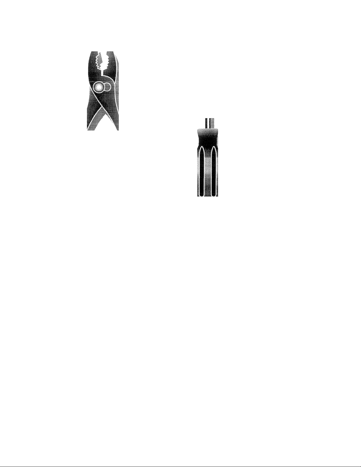
TOOLS REQUIRED FOR ASSEMBLY
A socket wrench set will make assembly easier. Standard
wrench sizes are listed.
(1) Utility knife
(1) Pair of pliers
(1) Screwdriver
(2) 1/2" wrenches
OPERATOR’S POSITION (See Fig. 1)
When right or left hand is mentioned in this manual, it
means when you are in the operating position (standing
behind tiller handles).
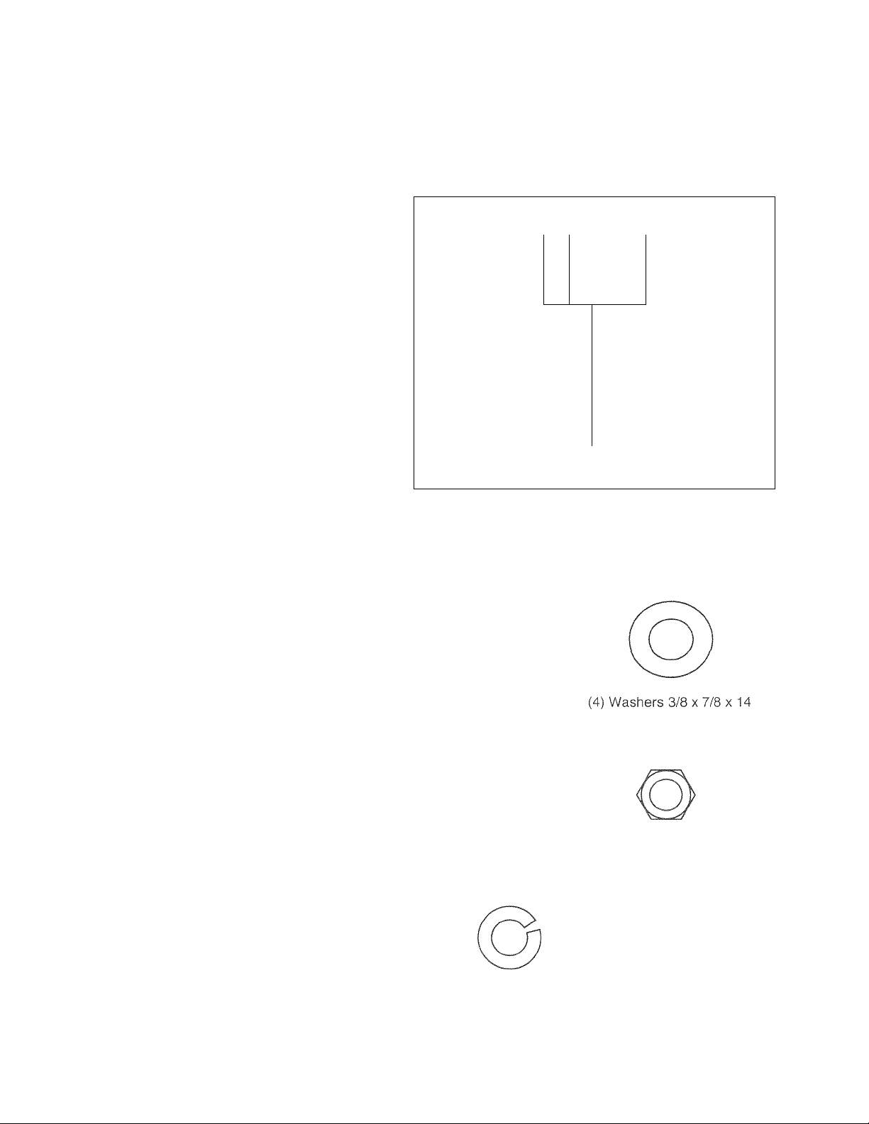
CONTENTS OF HARDWARE PACK
LEFT
FRONT
r|—
RIGHT
\=
OPERATOR'S
POSITION
FIG. 1
Bn
(2) Hex Bolts 5/16-18 X 3/4
(1) Cotter Pin
■ I
(2) Hex Bolts 5/16-18 x 1-1/4
§■1
(2) Hex Bolts 5/16-18 X 1
o
(1) Clevis Pin
(6) Lock Washers 5/16
(6) Hex Nuts 5/16-18
Page 6
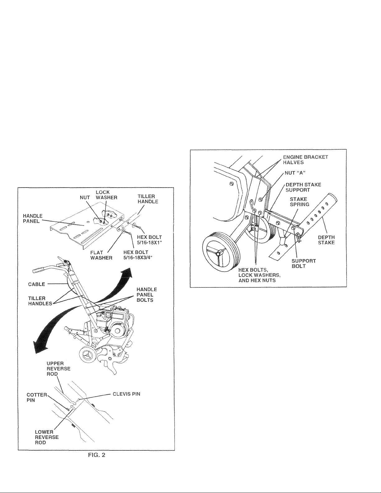
ASSEMBLY
UNPACK CARTON & INSTALL HANDLE (See
Fig. 2)
CAU!ION: Br c-dreful of exposed
siapies when handling or disposing of
A
IMPORTANT: WHEN UNI /CKING AND ASSEMBLING
TILLER, BE CAREFUL HCW 1C- STRETCH OR KiNK
CABLE(S).
® Cut cable ties securing handles.
• Slowly lift handle assembly up and align handle holes
with handle panel hole and slot.
« Loosely assemble hardware as shown. Be sure the
shorter (3/4" long) hex bolt is assembled in lower hole
of handle. Repeat for opposite side. Tighten all
hardware securely.
• Cut cable ties securing tiller to skid and remove tiller
from skid.
cartoning matori«h
IMi TAoL DEPTH STAKE ASSEMBLY
(See Fig. 3)
• Loosen nut “A".
• Insert stake support between engine bracket halves
• Bolt stake support to engine brackets with bolts, lock
• Depth stake must move freely. If it does not, loosen
INSTALL REVERSE ROD (See Fig. 2)
• Secure upper reverse rod to lower reverse rod using
with stake spring down.
washers and nuts. Tighten securely. Tighten nut “A”.
support bolt.
clevis pin. Secure with cotter pin.
FIG. 3
HANDLE HEIGHT
• Handle height may be adjusted to better suit operator.
(See “HANDLE HEIGHT” in the Service and Adjust
ments section of this manual).
TILLING WIDTH
• Tilling width may be adjusted to better handle your
tilling conditions (See “TINE ARRANGEMENT” in the
Service and Adjustments section of this manual).
TINE OPERATION
• Check tine operation before first use. (See “TINE
OPERATION CHECK” inthe Service and Adjustments
section of this manual).
Page 7
OPERATION
Kr^ow YOUR mi.Fu;
Pi Ail lHi\ OWNtR't' PA^JUAL AND SAFETY RULES BEFORE OPERATING YOUR TILLER.
f the illii u.-tini viJ I >/our tiller to familiarize yourself with the location of various controls and adjustments. Save
(hi % ftijiiij.il for lutuie fmf!'( e
The*^ iyrnoois niai rft t« oi on your Tiiler or in literature supplied wiin the product. Learn and understand their
meaning.
I
TlLLiNG FORWARD NEUTRAL REVERSE CAUTION ENGINE ENGINE
REVERSE
TINE
CONTROL
OR WARNING ON OFF
FAST OIL
STOP
o
MEETS ANSI SAFETY REQUIREMENTS
Our tillers conform to the safety standards of the American National Standards Institute.
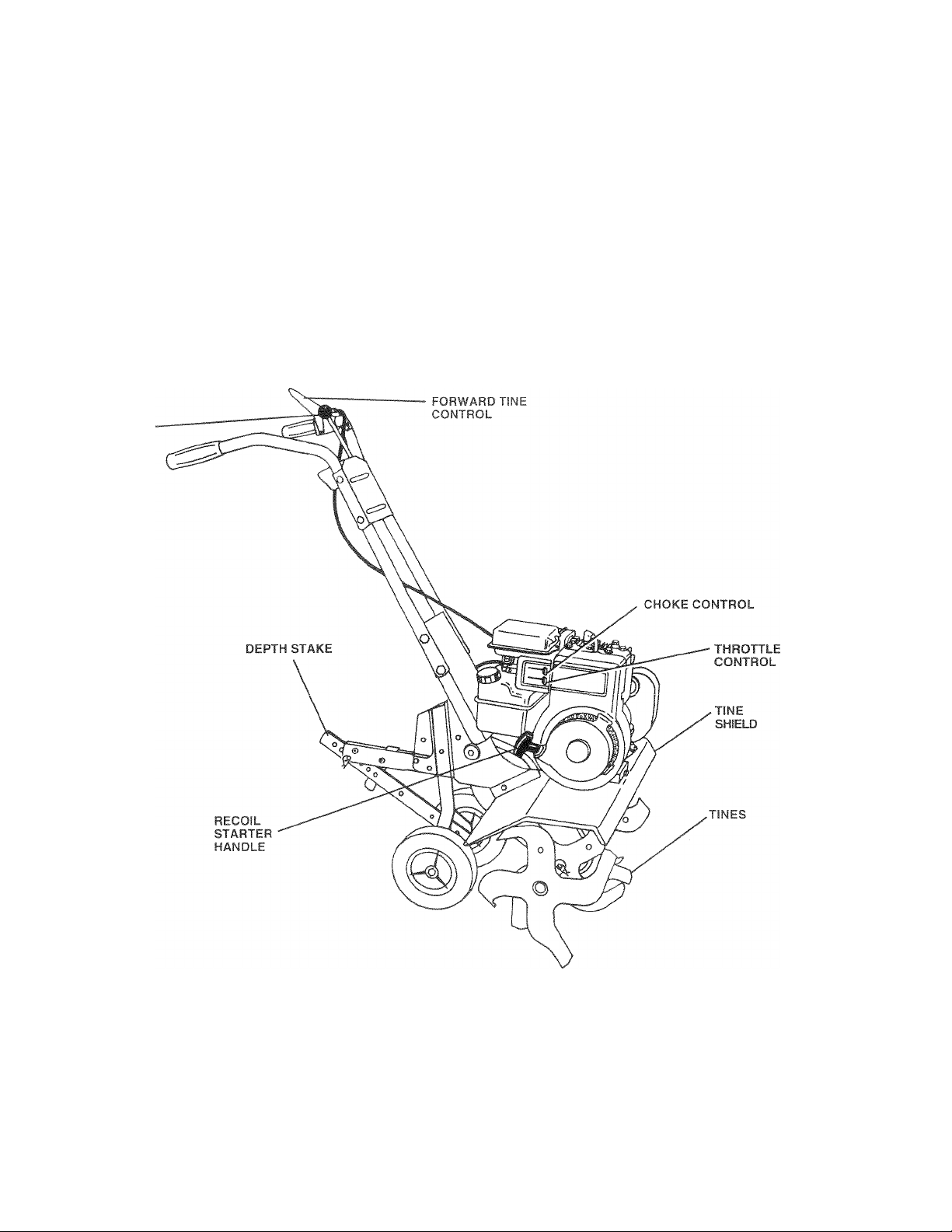
Forward tine control - Engages tines in forward
direction.
REVERSE TINE CONTROL - Engages tines in reverse
direction.
THROTTLE CONTROL - Controls engine speed.
FIG. 4
CHOKE Control - used when starting a cold engine.
DEPTH STAKE - Controls forward speed and the depth at
which the tiller will dig.
RECOIL STARTER HANDLE - Used to start the engine.
Page 8
OPERATION
The operation of any iilier car. recoi 11 i ‘^рун, ob;i t= ¡n ft -
f s*fCT?GussB j lesuit in severe eye damage. Alwr /s л/еа*' з‘"‘у gf e« c»r ey .lei i' t, i
your tilier and while tilling. We t •'■ irriit-io > w t- jKttrt o.c.i-iJ ,t« > f r
spccfacies or standaid e i. fy q> f -*
HOW TO USE YOUR TILLER
Know how to operate all controls before adding fuel and oil
or attempting to start engine.
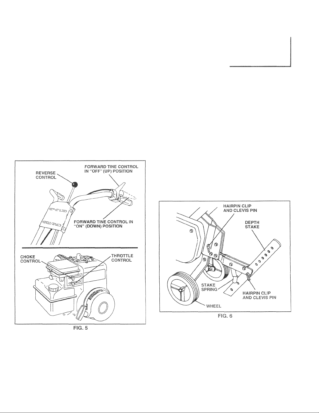
STOPPING (See Fig. 5)
TINES
• Release forward tine co n t r o l to stop forward move
ment.
• Release reverse tine control to stop reverse move
ment.
ENGINE
• Move throttle control to “STOP” position.
• Never use choke to stop engine.
TILLING
The speed and depth of tilling is regulated by the position
of the depth stake and wheel height.
The depth stake should always be below the wheels for
digging. It serves as a brake to slow the tiller’s forward
motion to enable the tines to penetrate the ground. Also,
the more the depth stake is lowered into the ground the
deeper the tines will dig.
DEPTH STAKE (See Fig. 6)
Adjust depth stake by removing the hairpin clip and clevis
pin. Change depth stake to desired position. Replace the
clevis pin and hairpin clip.
• For normal tilling, set depth stake at the second orthird
hole from the top.
WHEELS (See Fig. 6)
Adjust wheels by removing the hairpin clip and clevis pin.
Change wheel position. Replace the hairpin clip and clevis
pin.
• Fornormal tilling, set wheels at the second orthird hole
from the top.
>vi t
)ге starting
>r over the
TINE OPERATION (See Fig. 5)
FORWARD
• Squeeze forward tine control to handle.
REVERSE
• With forward tine control “OFF” (up) position, pull back
and hold reverse tine control.
8
Page 9

OPERATION
TO TRANSPORT
CAyJIOfJ- Before Ifftirtg er transpor!-
iog. allow erigitie arid muffler to
A
cool. Disconnect spat k plug #ire. Drain
gasoiiiie from fue! tank.
AROUND THE YARD
• Tip depth stake forward until it is held by the stake
spring.
• Push tiller handles down, raising tines off the ground.
• Push or pull tiller to desired location.
AROUND TO¥/N
• Disconnect spark plug wire.
• Drain fuel tank.
• Transport in upright position to prevent oil leakage.
BEFORE STARTING ENGINE
IMPORTANT: BE VERY CAREFUL NOT TO ALLOW DIRT
TO ENTER THE ENGINE WHEN CHECKING OR ADDING
OIL OR FUEL. USE CLEAN
IN APPROVED, CLEAN, COVERED CONTAINERS. USE
CLEAN FILL FUNNELS,
FILL ENGINE WITH OIL (See Fig. 7)
• With engine level, remove engine oil filler plug.
• Fill engine with oil to point of overflowing. For approxi
mate capacity see “PRODUCT SPECIFICATIONS” on
page 3 of this manual.
• Tilt tiller back on its wheels and then re-level.
• With engine level, refill to point of overflowing if neces
sary. Replace oil filler plug.
• For cold weather operation you should change oil for
easier starting (See “OIL VISCOSITY CHART” in the
Customer Responsibilities section of this manual).
• To change engine oil, see the Customer Responsibili
ties section of this manual.
OIL AND FUEL AND STORE
ADD GASOLINE
• Fill fuel tank. Use fresh, clean, regular unleaded
gasoline. (Use of leaded gasoline will increase carbon
and lead oxide deposits and reduce valve life.)
IMPORTANT: WHEN OPERATING IN TEMPERATURES
BELOW .32"F(0°C), USE FRESH, CLEAN. WINTER GRADE
GASOLINE TO HELP INSURE GOOD COLD WEATHER
STARTING.
WARNING F<oerience indicat-& ifiu* ^al* nfin' blended
fuels (callt-d ijasofiol or u mg rihat.ol ot m-^th uiol] can
attract moi'tur^whrh lec.J tc; sri ut ntion ..nd to’-mation of
acids nuriti j h I idic a ce n dari.t qt tfn- fuel
system cf vi ngir- wtiiL n ■'ton ge Tq avoid engine
problem' ( .el s*'*, u'd he »nptiecf before
storage of "*0 day^ or longer [>r < n the ''rj i '-■rp :f-rtthe
engine an'' W' ii run until the fuel line ird cj'Dur-Km are
empty. Use fresh fuel next season. See Storage section
of this manual for additional information. Never use engine
orcarburetorcleaner products inthe fuel tank or permanent
damage may occur.
CAUTION: Fill to within 1/2 inch of top
of fuel tank to prevent spills and to
allow for fuel expansion. If gasoline is
accidentally spilled, move machine
away from area of spill. Avoid creating
any source of ignition until gasoline
vapors have disappeared.
Do not overfill. Wipe off any spilled oil
or fuel. Do not store, spill or use gaso
line near an open flame.
TO START ENGINE (See Fig. 8)
CAUTION: Keep tine control in “OFF”
A
When starting engine for the first time or if engine has run
out of fuel, it will take extra pulls of the recoil starter to move
fuel from the tank to the engine.
• Make sure spark plug wire is properly connected.
• Place throttle control in “FAST” position.
• Move choke control to full “CHOKE” position. Grasp
recoil starter handle with one hand and grasp tiller
handle with other hand. Pull rope out slowly until
engine reaches start of compression cycle (rope will
pull slightly harder at this point).
• Pull recoil starter handle quickly. Do not let starter
handle snap back against starter. Repeat if necessary.
• If engine fires but does not start, move choke control to
half choke position. Pull recoil starter handle until
engine starts.
• When engine starts, slowly move choke control to
“RUN” position as engine warms up.
position when starting engine.
Page 10

OPERATION
NOTE: A warm engine requires less choking to start.
® Move throttle control to desired running position.
• Allow engine to warm up for a few minutes before
engaging tines.
NOTE: If at a high altitude (3000 feet) or in cold tempera
tures (below 32'T), the carburetorfuel mixture may need to
be adjusted for best engine performance. See “TO AD
JUST CARBURETOR” in the Service and Adjustments
section of this manual.
NOTE: If engine does not start, see troubleshooting points.
FIG. 8
BREAKING IN YOUR TILLER
Break-in your belt(s), pulleys and tine control before you
actually begin tilling.
• Start engine, tip tines off ground by pressing handles
down and engage tine c o n tr o l to start tine rotation.
Allow tines to rotate for five minutes.
• Check tine operation and adjust if necessary. See
“TINE OPERATION CHECK” in the Service and Ad
justments section of this manual.
TILLING HINTS
CAUTION: Until you are accustomed to
handling your tiller, start actual field
A
To help tiller move forward, lift up the handles slightly (thus
lifting depth stake out of ground). To slow down the tiller,
press down on handles.
If you are straining ortiller is shaking, the wheels and depth
stake are not set properly in the soil being tilled. The proper
setting of the wheels and depth stake is through trial and
error and depends upon the soil condition. (The harder or
wetter the ground, the slower the engine and tine speed
needed. Underthesepoorconditions, atfastspeedthe tiller
will run and jump over the ground),
A properly adjusted tiller will dig with little effort from the
operator.
use with throttle in slow position.
iq is diqqinq
Э clear th(
ill -I • I
De
sending c
ao
'isable to I
[0 l.irtn* I Ct.fiQUL Oil
Snikondition at imp .lantforfcoj/t rul!,iin 'r ill
ntl к idilv Pi nff'nir d i am '1 li V'hm.h rJ / (aitllpum 10 emejci'm и<ип( e and diffa ui* tiandl-na ut ynur
till-r. H ira Sill II iijid 1)0 t It i-rtonod bMon tiiimci;
novrevf r t xt MoO / wei Ч ii i)' / -¡1 nf, ,i - lurnp
during lillinq w n unul um oih m. „ w-w ■ > ij-r to
aci.icL ii,( l„ I , lit 'Vi n T ; ‘ - I ' , •
wncs nd I Hi )гг ‘ 1c i.ir ' -n h-o firm '« f pi j
around ihi lint Uuit md. lotonij y^u iibiMn opt r tian
You 1/Vi|i find lllhng r III' h оач-i f yOU I ) t tow
unTilled betv'Cf r p ^-m ГЬ«-п g i bacx ova fhr- f ntirc
area di lightanq.e t Fiq e) Thereareiw иостсао
for doing this РкМ \ 'id>- turns aie much (-awtr !c
negotiate than rocut fm pc Second ine tiller won t be
pulling t^di and''')U tov^sro il,e trw nedtr it
Set deptn stat' and vlmel height for stiallow tilling
v/hen vvo t Min ( xtieriii l> hud ooil oi -od Г hen v/orf
across tl la fir >f i ut nil mialfiepih
Гс 10 li
j jt.
„»D. ■ '.»■ ■ ,.«l "lUf ■ ■■
'("> turning over, ar
nting." Loose,
tilling depth is 4'
/anted vegetatic
. у i ,ble matter enr
^ . f,, I - III ^ Ui f V
I I ' ■ I I ■ I t L I U1 t It 'jl ‘Л I , ^tl
■'A- .................
i.
HniEELlfi:
aking up
eked" soi
"l!^ r vV|
Э decom-
the soil.
dt, it
nr 'txjr XI
YXZZl'lLX
FIG. 9
..
ж
CULTIVATING
Cultivating is destroying the weeds between rows to pre
vent them from robbing nourishment and moisture from
the plants. At the same time, breaking up the upper layer
of soil crust will help retain moisture in the soil. Best
digging depth is T'-3".
• You will probably not need to use the depth stake.
Begin by tipping the depth stake forward until it is held
by the stake spring,
• Cultivate up and down the rows at a speed which will
allow tines to uproot weeds and leave the ground in
rough condition, promoting no further growth of weeds
and grass (See Fig. 10).
10
Page 11

CUSTOMER RESPONSIBILITIES
MAINTENANCE
SCHEDULE
/■ /./ /
FILL IN DATES
AS YOU COMPLETE
REGULAR SERVICE
Check Engine Oil Level
Change Engine Oil
Oil Pivot Points
Inspect Spark Arrester / Muffler
Inspect Air Screen
Clean or Replace Air Cleaner Cartridge
Clean Engine Cylinder Fins
Replace Spark Plug
1 - Change mere often when operating under a heavy load or in high ambient temperatures.
2 - Service more often when operating in dirty or dusty conditions.
AO/
/A ^
✓
✓
r <0 / <^ / <0/
Av
7/§/§/ SERVICE DATES
/^/ A//
✓
<2
✓
✓
✓ 2
✓
✓
/77' 1
GENERAL RECOMWIENDATIONS
The warranty on this tiller does not cover items that have
been subjected to operator abuse or negligence. To
receive full value from the warranty, operator must main
tain tiller as instructed in this manual.
Some adjustments will need to be made periodically to
properly maintain your tiller.
All adjustments in the Service and Adjustments section of
this manual should be checked at least once each
season.
• Once a year you should replace the spark plug, clean
or replace air filter, and check tines and belts for wear.
A new spark plug and clean air filter assure proper airfuel mixture and help your engine run better and last
longer.
BEFORE EACH USE
• Check engine oil level.
• Check tine operation.
• Check for loose fasteners.
LUBRICATION
Keep unit well lubricated (See “LUBRICATION CHART”).
LUBRICATION CHART
ARM
‘ SAE 30 OR 10W-30 MOTOR OIL
** REFER TO CUSTOMER RESPONSIBILITIES “ENGINE” SECTION
11
Page 12

A
CUSTOMER RESPONSIBILITIES
Li!5Ci.mr>“ci Bpack pitsa wire petcre performing any maintenance (except carburetor adjustment) to prevent
t)CCKlent..if starting ct eng nt?.
P:£yr-ni firt's! Ke-to ihe rnginefree . ■ Ml, Ir ry. oil, oriuel. Remove fuel from tank before tipping
unit ior mointerrirtce. Clean muffle' *i - oiii. inc* debris.
Do not touch hot muffler or cylinder ‘tort, L'tos.
ENGINE
LUBRICATION
Use only high detergent oil rd^d with API service
classification £•“ ZC c ''C-1 -ct th - ~'l’s SAE viscosity
grade accoraing If 'u'li f.Ype* ted tr-mi'c-rature.
rEVFEP'^TURE H'-nr E AN S' FATED BEFORE I O T OIL CHi
FIG. 11
NOTE: Although multi-viscosity oils (5W-30,10W-30, etc.)
improve starting in cold weather, these multi-viscosity oils
will result in increased oil consumption when used above
32°F (0°C). Check your engine oil level more frequently to
avoid possible engine damage from running low on oil.
Change the oil after every 25 hours of operation or at least
once a year if the tractor is not used for25 hours in one year.
Check the crankcase oil level before starting the engine
and after each five (5) hours of continuous use. Add SAE
30 motor oil or equivalent. Tighten oil filler plug securely
each time you check the oil level.
AIR CLEANER (See Fig. 13)
Lf-r'ice -ir. leanercartridge every twenty-five hours, more
often ft f- ngine is used in very dusty conditions.
• Loosen air cleaner screws, one on each side of cover.
• Remove air cleaner cover.
• Carefully remove air cleaner cartridge. Be careful. Do
not allow dirt or debris to fail into carburetor.
• Clean by tapping gently on a flat surface.
• If very dirty or damaged, replace cartridge.
• Clean and replace cover. Tighten screws securely.
CAUTION: Petroleum solvents, such
as kerosene, are not to be used to clean
A
AIR
CLEANER
SCREW
cartridge. They may cause deteriora
tion of the cartridge. Do not oil car
tridge. Do not use pressurized air to
clean or dry cartridge.
COVER
AIR
CLEANER
CARTRIDGE
TO CHANGE ENGINE OIL (See Figs. 11 and 12)
Determine temperature range expected before oil change.
All oil must meet API service classification SF, SG or SH.
• Be sure tiller is on level surface.
• Oil will drain more freely when warm.
• Catch oil in a suitable container.
• Remove drain plug.
• Tip tiller forward to drain oil.
• After oil has drained completely, replace oil drain plug
and tighten securely.
• Remove oil filler plug. Be careful not to allow dirt to
enter the engine.
• Refill engine with oil. See “CHECK ENGINE OIL
LEVEL” in the Operation section of this manual.
FIG. 13
COOLING SYSTEM (See Fig. 14)
Your engine is air cooled. For proper engine performance
and long life keep your engine clean.
• Clean air screen frequently using a stiff-bristled brush.
• Remove blower housing and clean as necessary.
• Keep cylinder fins free of dirt and chaff.
Page 13

CUSTOMER RESPONSIBILITIES
MUFFLER
Do not operate tiller without muffler. Do not tamper with
exhaust system. Damaged mufflers or spark arresters
could create a fire hazard. Inspect periodically and replace
if necessary. If your engine is equipped with a spark
arrester screen assembly, remove every 50 hours for
cleaning and inspection. Replace if damaged.
SPARK PLUG
Replace spark plugs at the beginning of each tilling season
orafter every 50 hours of use, whichever comes first. Spark
plug type and gap setting are shown in “PRODUCT SPECI
FICATIONS” on page 3 of this manual.
SERVICE AND ADJUSTMENTS
CAUTION: Disconnect spark plug wire from spark plug and place wire where it cannot come into
A
TILLER
TO ADJUST HANDLE HEIGHT (See Fig. 15)
Factory assembly has provided lowest handle height. Se
lect handle height best suited for your tilling conditions.
Handle height will be different when tiller digs into soil.
• If a higherhandle height is desired, loosen the four nuts
securing handle panel to engine brackets.
• Slide handle panel to desired location.
• Tighten the four nuts securely.
contact with plug.
TRANSMiSSiON
Your transmission is sealed and will not require lubrication
unless servicrx'.
CLEANING
® Clean engine, wheels, finish, etc. of aii foreign matter.
• Keep finished surfaces and wheels free of all gasoline,
oil, etc.
• Protect painted surfaces with automotive type wax.
We do not recommend using a garden hose to clean your
unit unless the muffler, air filter and carburetor are covered
to keep waterout. Water in engine can result in a shortened
engine life.
TINE ARRANGEMENT
Youroutertinescan be assembled in several different ways
to suit your tilling or cultivating needs.
CAUTION: Tines are sharp. Wear
gloves or other protection when han
A
NORMAL TILLING - 26" PATH (See Fig. 16)
• Assemble holes “A” in tine hubs to holes “B” in tine
shaft.
dling tines.
13
Page 14

SERVICE AND ADJUSTMENTS
MID^WIDTH TILLING ^ 24“ PATH (See Fig, 171
• Assemble holes “A” in tine hubs to holes “C" in tine
shaft.
( .
O ; i O
o
J.jot
1
FIG. 17
NARROW TILLING/CULTIVATiNG ^ 12-3/4" PATH (See
Fig. 18)
» Remove outer tines.
iV
1
■ i "o' I
'
FINAL CHECK “ON” POSITION
With tine contro
on handle to ra
I' N 1/ LCM, > !l 1 I ti fi ( Ij '
11 es nr I ii(i 1 t<- 1 \'i .If i
liiP_ hr , n I|| f VKS ’ npliol ( role IS u n
lOose Lou-i-ti Cdtlf Clip idpuliuabK up lO lemove
siacK ana rengnien cup.
• Recheck in “ON” position and adjust if necessary.
NOTE: If “ON” position check required adjustment, re
check “OFF” position adjustment to insure tines do not
rotate when control is “OFF" (up).
FORWARD TINE CONTROL
hi (fir, '111 , n|pi
íes off the ground.
hdown
bservinq tines.
NOTE: When reassembling outer tines, be sure right tine
assembly (marked “R”) and left tine assembly (marked “L”)
are mounted to correct side of tine shaft.
TINE OPERATION CHECK (See Fig. 19)
WARNING: Disconnect spark plug wire
from spark plug to prevent starting
A
Forpropertine operation, forward tine control lever must be
against control body and all slack removed from inner wire
of control cable when control is in the “OFF” (up) position.
If lever and cable are loose, loosen cable clip at lower end
of cable. Pull up on cable to remove slack, without
extending spring on end of cable, and retighten cable clip.
FINAL CHECK “OFF” POSITION
• With tine control “OFF” (up), push down on handle to
raise tines off the ground.
• Slowly pull recoil starter handle while observing tines.
Tines should not rotate.
• If tines rotate, inner wire of control cable is too tight
which is extending lower spring and engaging tines.
Loosen cable clip and push down on cable only enough
to relieve spring tension. Tighten cable clip.
• Recheck in “OFF” position and adjust if necessary.
while checking tine operation.
CABLE
CLIP
FIG. 19
14
Page 15

SERVICE AND ADJUSTMENTS
r V F%{ Tt U -r.-*21)
lu I I, , ii , , r i( ( ,n id ,)t)i j ur if
rtif 11 W r J ^ s • I
••if-lts forwcird (ill
>■ K I'i ’»■H I L,si [' '■ T(
REMOVE BELT GUARD
NOTE: Observe carefully routing of both belts and location
of ail belt guides before removing belts.
BELT REMOVAL
• Remove reverse idler pulley from idler arm.
• Remove reverse (outside) V-belt.
• Remove forward (inside) V-belt from transmission pul
ley first and then from engine pulley.
BELT REPLACEMENT
• Install new forward (inside) V-belt to engine pulley first
then to transmission pulley. Be sure belt is positioned
on inside groove of both pulleys, inside ail belt guides
and rests on idler pulley.
• Before installing reverse (outside) V-belt, turn belt
“inside out”. Twist so wide, flat surface of belt is to
inside.
• Wrap V-belt around reverse idler pulley and reas
semble idler to idler arm. Tighten securely. Be sure
belt is between reverse idler pulley and idler arm pin.
• Install belt to outside groove of transmission pulley. Be
sure belt is inside all belt guides and rests on outside
groove of engine
CHECK TINE OPERATION
• See “TINE OPERATION CHECK” in this section of
manual.
REPLACE BELT GUARD
' V I r |i I i[|f
K Vi
/ed edge
nc It Vf t
'sd to service belts. See “TO
in this section of manual.
pulley.
There are two (2) Vjufside).
Page 16

SERVICE AND ADJUSTMENTS
TO REMOVE ‘JTRD {Se e Fig. 22)
» Remove t.vo(l) cap nutf,;-r..jwa -her’ from side of belt
guard.
• Loosen (do not remove) tine shield nut on underside of
tine shield.
* Pull belt guard out and away from unit.
» Replace belt guard by reversing above procedure. Be
sure slot in bottom of belt guard is under head of tine
shield bolt and all nuts are tightened securely.
c Vviti', t 111 r,id ,|I, I ■ '/”f,o' I, 1 ji,> 1 d ii'idl
, I r- i VI *- M , t I |. 1 f' 1 d| i| < I , J. I I
Cl. t (' I hi li '<1 >. ,M' i i ni)i| » ni,t KlIJ'I ' U'M
V'tl i( ih C <» 'I'l lliid.i' 13 : 1 J;i/r 1-11 'i . • ( tvvi p jc itl' If.
IDLE RPM ADJUSTMENT
• 'To adjust idle RPM, rotate throttle linkage counterclock
wise and hold against stop while adjusting idle speed
adjusting screw to obtain 1750 RPM. Release throttle
linkage.
ACCELERATION TEST
• Move throttle control lever from “SLOW” to “FAST”
position, if engine hesitates or dies, turn idle needle
valve out (counterclockwise) 1/8 turn. Repeat test and
continue to adjust, if necessary, until engine acceler
ates smoothly.
High speed stop is factory adjusted. Do not adjust or
damage may result.
IMPORTANT: NEVER TAMPER WITH THE ENGINE
GOVERNOR, WHICH IS FACTORY SET FOR PROPER
ENGINE SPEED. OVERSPEEDING THE ENGINE ABOVE
THE FACTORY HIGH SPEED SETTING CAN BE
DANGEROUS. IF YOU THINK THE ENGINE-GOVERNED
HIGH SPEED NEEDS ADJUSTING, CONTACT YOUR
NEAREST AUTHORIZED SERVICE CENTER/
DEPARTMENT, WHICH HAS THE PROPER EQUIPMENT
AND EXPERIENCE TO MAKE ANY NECESSARY
ADJUSTMENTS.
FIG. 22
ENGINE
TO ADJUST CARBURETOR (See Fig. 23)
The carburetor has a high speed fixed jet and has been
preset at the factory and adjustment should not be neces
sary. However, minor adjustments may be required to
compensate for differences in fuel, temperature, altitude or
load. If the carburetor does need adjustment, proceed as
follows.
In general, turning the idle needle valve in (clockwise)
decreases the supply of fuel to the engine giving a leaner
fuel/air mixture. Turning the needle valve out (counter
clockwise) increases the supply of fuel to the engine giving
a richer fuel/air mixture.
IMPORTANT; DAMAGE TO THE NEEDLES AND THE
SEATS IN CARBURETOR MAY RESULT IF SCREWS ARE
TURNED IN TOO TIGHT.
PRELIMINARY SETTING
• Air cleaner assembly must be assembled to the carbu
retor when making carburetor adjustments.
• With engine off, turn idle needle valve in (clockwise)
closing it finger tight and then turn valve out (counter
clockwise) 1-1/2 turns.
FINAL, SETTING
• Start engine and allow to warm for five minutes. Make
final adjustments with engine running at idle and tine
control lever in “OFF” position.
16
Page 17

STORAGE
Immediately prepare your tiller for storaqc et the end of the
season or if the unit wiil not t)0 used foi f.o d.i/-. or more.
CjàUTICN; ficrfer sioft lie iiller «■ Hi
gasoline in the tani* lOaicfe j building
'«here foiTie.s may reach a?’ open fiomc-
A
or spark Alio« the erigine lo oooi
before storing in any enclosure.
TILLER
® Clean entire tiller (See “CLEANING” in the Customer
Responsibilities section of this manual).
• Inspect and replace belts, if necessary (See belt re
placement instructions in the Service and Adjustments
section of this manual).
• Lubricate as shown in the Customer Responsibilities
section of this manual.
• Be sure that all nuts, bolts and screws are securely
fastened. Inspect moving parts for damage, breakage
and wear. Replace if necessary.
• Touch up all rusted or chipped paint surfaces; sand
lightly before painting.
ENGINE
FUEL SYSTEM
IMPORTANT: IT IS IMPORTANT TO PREVENT GUM
DEPOSITS FROM FORMING IN ESSENTIAL FUEL
SYSTEM PARTS SUCH AS THE CARBURETOR, FUEL
FILTER, FUEL HOSE, OR TANK DURING STORAGE.
ALSO, EXPERIENCE INDICATES THAT ALCOHOL
BLENDED FUELS (CALLED GASOHOL OR USING
ETHANOL OR METHANOL) CAN ATTRACT MOISTURE
WHICH LEADS TO SEPARATION AND FORMATION OF
ACIDS DURING STORAGE. ACIDIC GAS CAN DAMAGE
THE FUEL SYSTEM OF AN ENGINE WHILE IN STORAGE.
• Drain the fuel tank,
• Start the engine and let it run until the fuel lines and
carburetor are empty.
• Never use engine or carburetor cleaner products in the
fuel tank or permanent damage may occur.
• Use fresh fuel next season.
NOTE: Fuel stabilizer is an acceptable alternative in
minimizing the formation of fuel gum deposits during stor
age. Add stabilizer to gasoline in fuel tank or storage
container. Always follow the mix ratio found on stabilizer
container. Run engine at least 10 minutes after adding
stabilizer to allow the stabilizer to reach the carburetor. Do
not drain the gas tank and carburetor if using fuel stabilizer.
ENGINE OIL
Drain oil (with engine warm) and replace with clean oil.
(See “ENGINE” in the Customer Responsibilities section of
this manual).
CYLINDERS
Remove spark plug.
Pour 1 ounce (29 ml) of oil through spark plug hole into
cylinder.
Pull starter handle slowly several times to distribute oil.
Replace with new spark plug.
OTHER
Do not store gasoline from one season to another.
Replace your gasoline can if your can starts to rust.
Rust and/or dirt in your gasoline will cause problems.
If possible, store your unit indoors and cover it to give
protection from dust and dirt.
Cover your unit with a suitable protective cover that
does not retain moisture. Do not use plastic. Plastic
cannot breathe which allows condensation to form and
will cause your unit to rust.
IMPORTANT: NEVER COVER TILLER WHILE ENGINE
AND EXHAUST AREAS ARE STILL WARM.
17
Page 18

TROUBLESHOOTING POINTS
PROBLEM CAUSE
Will not start 1. Out of fuel.
2. Engi.ne not “CHOKED" properly,
3. Engine flooded.
4. Dirty air cleaner.
5. Water in fuel.
6. Clogged fuel tank.
7. Loose spark plug wire,
8. Bad spark plug or improper gap.
9. Carburetor out of adjustment.
Hard to start 1. Throttle control not set properly,
2. Dirty air cleaner,
3. Bad spark plug or improper gap.
4. Stale or dirty fuel.
5. Loose spark plug wire.
6. Carburetor out of adjustment.
Loss of power 1. Engine is overloaded.
2. Dirty air cleaner.
3. Low oil level/dirty oii,
4. Faulty spark plug,
5. Oil in fuel.
6. Stale or dirty fuel.
7. Water in fuel.
8. Clogged fuel tank.
9. Spark plug wire loose.
10. Dirty engine air screen.
11, Dirty/ctogged muffler.
12. Carburetor out of adjustment.
13, Poor compression.
CORRECTION
1. Fill fuel tank.
2. See “TO START ENGINE" in the Operation section.
3. Wait several minutes before attempting to siaP.
4. Clean or replace air cleaner cartridge.
5. Drain fuel tank and carburetor, and refill tank with
fresh gasoline,
6. Remove fuel tank and clean.
7. Make sure spark plug wire is seated properly on plug.
8. Replace spark plug or adjust gap.
9. Make necessary adjustments.
1. Place throttle control in '‘FA-ST” position.
2. Clean or replace air cleaner cartridge.
3. Replace spark plug or adjust gap.
4. Dram fuel tank and refill with fresh gasoline.
5. Make sure spark plug wire is seated properly on plug,
6. Make necessary adjustments.
1. Set depth stake and wheels for shallower tilling.
2. Clean or replace air cleaner cartridge.
3. Check oil leveLchange oil,
4. Clean and regap or change spark plug.
5. Drain and clean fuel tank and refill, and clean
carburetor,
6. Dram fuel tank and refill with fresh gasoline.
7. Drain fuel tank and carburetor, and refill tank with
fresh gasoline.
8. Remove fuel tank and clean.
9. Connect and tighten spark plug wire.
10. Clean engine air screen.
11. Clean/replace muffler,
12. Make necessary adjustments.
13. Contact an authorized service center/department.
Engine overheats 1. Low oil level/dirty oil,
Excessive bounce/
difficult handling
Soil balls up or clumps 1, Ground too wet.
Engine runs but tiller 1, Tine control is not engaged. 1. Engage tine control.
won’t move 2. V-belt not correctly adjusted.
Engine runs but labors
when tilling
2. Dirty engine air screen.
3. Dirty engine.
4. Partially plugged muffler.
5. Improper carburetor adjustment.
1. Ground too dry and hard.
2. Wheels and depth stake incorrectly adjusted.
3. V-belt Is off puileyjs).
1. Tilling too deep. 1. Set depth stake for shallower tilling.
2. Throttle control not properly adjusted.
3. Carburetor out of adjustment.
1. Check oil level/change oil.
2. Clean engine air screen.
3. Clean cylinder fins, air screen, muffler area.
4. Remove and clean muffler.
5. Adjust carburetor to richer position.
1. Moisten ground or wait for more favorable soil
condilions,
2. Adjust wheels and depth stake.
1, Wait for more favorable soil conditions.
2, Inspecf/adjust V-beit.
3. Inspect V-belt.
2. Check throttle control setting.
3. Make necessary adjustments.
18
Page 19

REPAIR PARTS
HANDLE ASSEK
TILLER - - MODEL NUMBER CHDF550C
1
^ /
V r>
KEY
NO.
10 10040500
11 73220500
12 98000129
13
1416674A150428
PART
NO.
1 131268X428 Bracket, Handle 17 106932X
2 72140512
3 9266R
4 153138 Handle, L.H.
5 73680500
19111116
6
7 19121414
8 74760516
9 74760512
72140506
153139
DESCRIPTION KEY
NO.
Bolt, Carriage 5/16-18 UNC x 1-1/2
Grip, Handle
Locknut. Crown 5/16-18
Washer 11/32 x 11/16 x 16 Ga.
Washer 3/8 x 7/8 x 14 Ga.
Bolt, Hex Hd. 5/16-18 X 1
Bolt, Hex Hd 5/16-18 x 3/4
Washer, Lock 5/16
Nut, Hex 5/16-18
Nut, Flanged 5/16-18
Bolt, Carriage 5/16-18 x 3/4 Gr, 5
Panel, Handle
Handle, R.H.
18 3066J Cable, Control, Tine
19
20
21
22 101248K Rod, Reverse, Upper
23
24 2613J
25 19131316
26 76020412 Pin. Cotter 1 /8 X 3/4
27 76020308 Pin. Cotter 3/32 X 1/2
28
29
NOTE: Allcomponentdimensionsare given in U.S. inc
PART
NO.
151229
154805
12000027 Ring, Klip
1778E
19131312
12000059 Retaining, Ring
19
DESCRIPTION
Knob, Control, Reverse
Lever, Control, Tine
Pin, Pivot
Pin, Retaining
Rod. Reverse. Lower
Washer 13/32 x 13/16 x 16 Ga.
Washer 13/32 x 13/16 x 12 Ga.
1 inch = 25.4 mm
Page 20

REPAIR PARTS
TILLER ^ MuUl. tIUJBER CHDF550C
BELT GUARD AND i c ' A iSEMLi
KEY PART
NO.
10
11
12
13
14 133035 V-Belt (Forward Motion)
15
16 12000028
17182649M
NO.
1 159268
9484R Clip. Cable
2
86777
3
74610812
4
73220600
5
19131316
6
7 2009J
127180X
8
9 74760628
156705X428 Guard, Beit
19091016 Washer 9/32 x 5/8 x 16 Ga.
104213X Nut, Cap 1/4- 20
72140405 Bolt, Carriage 1/4-20 x 5/8
2614J V-Belt (Reverse)
151236
DESCRIPTION
Assembly, Bracket, Belt Guard
Screw, Hex, Washer Hd., Slotted,
Thd. Cutting #10-24 x 1/2 Type D
Bolt, Hex 1 /2-20 x 3/4
Nut, Hex 3/8-16
Washer 13/32 x 13/16 x 16 Ga,
Pulley, Idler, Reverse
Assembly, Arm, Reverse Idler
Bolt, Hex 3/8-16 X 1-3/4
Ring, Retainer
Key, Square
Pulley, Flat, Trans.
KEY
NO.
19
20 12000036
21 73350600
22 161806
23
24 74760620
25
26
27
28 10040400
29
30
31
32 151223
33 73510400
34
PART
NO.
110550X
162290
106968X Shaft, Idler Arm
73350500
73220400 Nut, Fin Hex 1/4-20
109227X
23200404
101189L Sheave, Engine
19091416
DESCRIPTION
Bolt, Belt Guard
Ring. Klip
Nuti Hex, Jam 3/8-16
Pulley, Idler
Arm. Idler
Bolt, Hex 3/8-16 x 1-1/4
Nut, Hex, Jam 5/16-18
Washer LK Hvy Helical 1/4
Pad, Idler
Screw, Set, Socket, Headless
C.P. 1/4-20 X 1 /4
Pulley, V-Groove, Trans.
Nut Keps Hex 1/4-20
Washer 9/32 x 7/8 x 16 Ga.
NOTE; Ail component dimensions given in U.S. in
1 inch = 25.4 mm
20
Page 21

REPAIR PARTS
TILLER - - MQLH iti^BER CHDF550C
WHEEL AND DEPTH STAKE ASSEMBLY
KEY
NO.
10
11
12
13
PART
NO.
9194R Pin, Clevis
1
74760520
2
74760512
3
73220500
4
10040500
5
73800600
6
4921H
7
1952J
8
122233X
9
326J
74780628
74760524
1951J
DESCRIPTION
Bolt, Hex 5/16-18 X 1-1/4
Bolt, Hex 5/16-18 X 3/4
Nut, Hex 5/16-18
Washer, Lock 5/16
Locknut, w/washer 3/8-16
Clip, Hairpin
Support, Depth Stake, R.H.
Stake, Depth
Pin, Clevis
Bolt, Hex, Fin 3/8-16 x 1-3/4
Bolt, Hex 5/16-18 x 1-1/2 Gr. 2
Support, Depth Stake, L.H.
KEY
NO.
14
15 5388J
16 121117X Bolt, Shoulder
17 9188R
18 19131311 Washer 13/32 x 13/16 x 11 Ga.
19 9190R
20 73680600
21
22
NOTE: All component dimensions given in U.S. inch
PART
NO.
120958X
74760516 Bolt, Hex 5/16-18 X 1
73800500 Locknut, w/insert 5/16-18
1 inch = 25.4 mm
DESCRIPTION
Washer
Spring, Stake
Wheel
Bracket, Wheel
Locknut, Crown 3/8-16
21
Page 22

REPAIR PARTS
TINE ASSEMBLY
TILLEP, ^ ^
KEY
NO.
1 156934
2 3146R
3 156932
PART
NO.
DESCRIPTION
Tine, Outer, R.H.
Clip, Hairpin
Tine, Inner, R.H.
22
KEY
NO.
4
5
6
PART
NO.
156931
156933
4929H
DESCRIPTION
Tine, Inner, L.H.
Tine, Outer, L.H.
Pin, Clevis
Page 23

REPAIR PARTS
TRANSMISSION
TILLER ^ - MODEL NUMBFr, ' J4^/L550C
KEY
NO. NO.
10
11
12 151222
PART
74760524
1
74780652
2
19131311
3
73800600
5
9057R428 Shield, Tine
6
7
1949J
8 1948J
9 10040500
73220500 Nut, Hex 5/16-18
74760544 Bolt, Hex 5/16-18 X 2-3/4
DESCRIPTION
Bolt, Hex 5/16-18 X 1-1/2 Gr. 2
Bolt, Hex, Fin 3/8-16 x 3-1/4
Washer 13/32 x 13/16 x 11
Locknut, Hex, w/washer 3/8-16
Bracket, Engine, R.H.
Bracket, Engine, L.H.
Washer, Lock 5/16
Transmission
KEY PART DESCRIPTION
NO.
13
14
15
16
17
18
19
20
NO.
19171616 Washer 17/32 x1 x 16 Ga.
9173R Spacer, Split
73510500 Nut, Keps 5/16
19091412 Washer 9/32 x 7/8 x 12 Ga.
19092016 Washer 9/32 x 1-1/4 x 16 Ga.
10040400 Washer, Lock 1/4
74610412 Bolt, Hex 1 /4-28 x 3/4 Gr. 5
Engine, Briggs and Stratton, Model
No. 137202
NOTE: All component dimensions given in U.S. inches.
1 inch = 25,4 mm
23
Page 24

REPAIR PARTS
DECALS
"kLCTo -IVlvriF-L ^hn\hBth( hUiP350C
KEY
NO.
1 157377 Decal, Logo
2 157380
3
4
5 110614X
6
7 271948 Decal, Briggs & Stratton
8 120076X
9 157381 Decal, Hvy Duty
10 273721 Decal, 5 HP
11 162384 Decal, Warning Till
PART
NO.
157378 Decal, HP, Reverse
121753X Decal, Reverse, Tine Control
110612X
163760 Manual, Owner’s (English)
163761 Manual, Owner’s (French)
DESCRIPTION
Decal, Logo
Decal, Hand Placement
Decal, Caution
Decal, Warning, Rotating Tines
24
 Loading...