

Page 1
1>0 Mbt HGM O
\k.
■m i
OWNER'S MANUAL
MODEL NO. HD145H42H
14.5 HP 42 Inch
Lawn Tractor
Assembly
• Operation
• Customer Responsibilities
• Service and Adjustments
• Storage
• Troubleshooting
• Repair Parts
For Parts and Service, contact our authorized distributor; call 1-800-849-1297
For Technical Assistance: call 1-800-829-5886
HLE
COPY
Poulan
163022 11.13.97 RD
PRINTED IN U.S.A.
Page 2

SAFETY RULES
Safe Operation Practices for Ride-On Mowers
IMPORTANT: THIS CUTTING MACHINE IS CAPABLE OF AMPUTATING HANDS AND FEET AND THROWING OBJECTS.
FAILURE TO OBSERVE THE FOLLOWING SAFETY INSTRUCTIONS COULD RESULT IN SERIOUS INJURY OR DEATH.
A
GENERAL OPERATION
Read, understand, and follow all instructions in the manual
and on the machine before starting.
Only allow responsible adults, who are familiar with the
instructions, to operate the machine.
Clear the area of objects such as rocks, toys, wire, etc.,
which could be picked up and thrown by the blade.
Be sure the area is clear of other people before mowing. Stop
machine if anyone enters the area.
Never carry passengers.
Do not mow in reverse unless absolutely necessary. Always
look down and behind before and while backing.
Be aware of the mower discharge direction and do not point
it at anyone. Do not operate the mower without either the
entire grass catcher or the guard in place.
Slow down before turning.
Never leave a running machine unattended. Always turn off
blades, set parking brake, stop engine, and remove keys
before dismounting.
Turn off blades when not mowing.
Stop engine before removing grass catcher or unclogging
chute.
Mow only in daylight or good artificial light.
Do not operate the machine while under the influence of
alcohol or drugs.
Watch for traffic when operating near or crossing roadways.
Use extra care when loading or unloading the machine into
a trailer or truck.
II. SLOPE OPERATION
Slopes are a major factor related to loss-of-control and
tipover accidents, which can result in severe injury ordeath.
All slopes require extra
caution. If you cannot back up the
slope or if you feel uneasy on it, do pot mow it.
DO:
Mow up and down slopes, not across.
Remove obstacles such as rocks, tree limbs, etc.
Watch for holes, ruts, or bumps. Uneven terrain could
overturn the machine. Ta// grass can hide obstacles.
Use slow speed. Choose a low gear so that you will not have
to stop or shift while on the slope.
Follow the manufacturer’s recommendations for wheel
weights or counterweights to improve stability.
Use extra care with grass catchers or other attachments.
These can change the stability of the machine.
Keep all movement on the slopes stow and gradual. Do not
make sudden changes in speed or direction.
Avoid starting or stopping on a slope. If tires lose traction,
disengage the blades and proceed slowly straight down the
slope.
DO NOT:
• Do not turn on slopes unless necessary, and then, turn slowly
and gradually downhill, if possible.
• Do not mow near drop-offs, ditches, or embankments. The
mower could suddenly turn over if a wheel is over the edge
of a cliff or ditch, or if an edge caves in.
• Do not mow on wet grass. Reduced traction could cause
sliding,
• Do not try to stabilize the machine by putting your foot on the
ground.
• Do not use grass catcher on steep slopes.
III. CHILDREN
Tragic accidents can occur if the operator is not aiert to the
presence of children. Children are often attracted to the
machine and the mowing activity. Never assume that
children will remain where you last saw them.
• Keep children out of the mowing area and under the watchful
care of another responsible adult.
• Be alert and turn machine off if children enter the area.
• Before and when backing, look behind and down for small
children.
• Never cari^ children. They may fall off and be seriously
injured or interfere with safe machine operation.
• Never allow children to operate the machine.
• Use extra care when approaching blind corners, shrubs,
trees, or other objects that may obscure vision.
IV. SERVICE
• Use extra care in handling gasoline and other fuels. They are
flammable and vapors are explosive.
Use only an approved container.
Never remove gas cap or add fuel with the engine
running. Allow engine to cool before refueling. Do not
smoke.
Never refuel the machine indoors.
Never store the machine or fuel container inside where
there is an open flame, such as a water heater.
• Never run a machine inside a closed area.
• Keep nuts and bolts, especially blade attachment bolts, tight
and keep equipment in good condition.
• Never tamper with safety devices. Check their proper
operation regularly.
• Keep machine free of grass, leaves, or other debris build-up.
Clean oil or fuel spillage. Allow machine to cool before
storing.
• Stop and inspect the equipment if you strike an object.
Repair, if necessary, before restarting.
• Never make adjustments or repairs with the engine running.
• Grass catcher components are subject to wear, damage, and
deterioration, which could expose moving parts or allow
objects to be thrown. Frequently check components and
replace with manufacturer's recommended parts, when nec
essary.
• Mower blades are sharp and can cut. Wrap the blade(s) or
wear gloves, and use extra caution when servicing them.
• Check brake operation frequently. Adjust and service as
required.
Look for this symbol to point out im
portant safety precautions. It means
CAUTION!!! BECOME ALERT!!! YOUR
A.
SAFETY IS INVOLVED.
CAUTION: Always disconnect spark plug
wire and place wire where it cannot contact
spark plug in order to prevent accidental
ik
starting when setting up, transporting,
adjusting or making repairs.
A WARNING ^
The engine exhaust from this product con
tains chemicals known to the State of Califor
nia to cause cancer, birth defects, or other
reproductive harm.
Page 3

CONGRATULATIONS on your purchase of a new tractor.
It has been designed, engineered and manufactured to
give you the best possible dependability and performance.
Should you experience any problem you cannot easily
remedy, please contact your nearest authorized service
center/department. We have competent, well-trained tech
nicians and the proper tools to service or repair this tractor.
Please read and retain this manual. The instructions will
enable you to assemble and maintain your tractor properly.
Always observe the “SAFETY RULES”.
MODEL
NUMBER
HD145H42H
SERIAL
NUMBER
DATE OF PURCHASE.
THE MODELANDSERIALNUMBERSWILL BE FOUND
ON A PLATE UNDER THE SEAT.
YOU SHOULD RECORD BOTH SERIAL NUMBER AND
DATE OF PURCHASE AND KEEP IN A SAFE PLACÉ
FOR FUTURE REFERENCE. .
CUSTOMER RESPONSIBILITIES
• Read and observe the safety rules.
• Followa regular schedule in maintaining, caring forand
using your tractor.
• Follow the instructions under “Customer Responsibili
ties” and “Storage” sections of this owner’s manual.
PRODUCT SPECIFICATIONS
HORSEPOWER: 14.5
GASOLINE CAPACITY
AND TYPE:
OIL TYPE (API-SF/SG/SH): SAE 30 (above 32°F)
OIL CAPACITY:
SPARK PLUG:
(GAP: .030“)
VALVE CLEARANCE:
GROUND SPEED (MPH): FORWARD: 4.7
TIRE PRESSURE:
CHARGING SYSTEM: 3 AMPS BATTERY
BATTERY:
BLADE BOLT TORQUE:
WARNING: This tractor is equipped with an internal
combustion engine and should not be used on or near any
unimproved forest-covered, brush-covered or grass-cov
ered land unless the engine’s exhaust system is equipped
with a spark arrester meeting applicable local or state laws
(if any). If a spark arrester is used, it should be maintained
in effective working order by the operator. ■
A spark arrester for the muffler is available through your
nearest authorized service center/department (See RE
PAIR PARTS section of this manual).
In the state of California the above is required by law
(Section 4442 of the California Public Resources Code).
Other states may have similar laws. Federal laws apply on
federal lands.
2 GALLONS
UNLEADED REGULAR
SAE 5W-30 (below 32°F)
3.0 PINTS
CHAMPION RJ19LM
INTAKE: .005" - .007“
EXHAUST: .009"-.011"
REVERSE: 2.2
FRONT: 14PSI
REAR: 12 PSI
5 AMPS HEADLIGHTS
AMP/HR: 25
MIN. CCA: 190
CASE SIZE; U1R
27-35 FT. LBS.
Page 4

TABLE OF CONTENTS
SAFETY RULES.......................................................... 3
PRODUCT SPECIFICATIONS
CUSTOMER RESPONSIBILITIES
................................................ 3
........
.......................
3. 15-19
WARRANTY......................................................................... 50
ASSEMBLY
OPERATION
..........
.................................................................
.......................................................................
6-9
10-14
INDEX
A
Adjustments;
Brake.................................................22
Carburetor
Mower
Throttle Control Cable
Air Filter, Engine
Air Screen, Engine
Assembly
......................................
Front-To-Back
Side-To-Side
.................................................
............................
...............................
.....................
......................................
...................................
B
Battery:
Charging
Cleaning............................................17
Starting with Weak Battery
Storage..............................................26
Terminals
Belt:
Motion Drive
Mower Belt(s)
Biade:
Sharpening
Replacement.....................................16
Brake Adjustment
.............................................
..........................................
Rem ovat/Replacem ent
Removal/Replacement
......................................
....................................22
C
Carburetor Adjustment
Controls, Tractor
Customer Responsibilities
Engine:
Air Filter........................................
Air Screen
Cooling Fins
Engine Oil................................13,17
Fuel Filter......................................19
Spark Plug(s).............................. 19
T ractor:
Battery
..........................................
Blade
............................................
Lubrication Chart.........................15
Maintenance Schedule
Tire Care
Transaxle
Cutting Height, Mower
............................
.....................................
................
.....................................
.................................
................
...............................
......................................
.............................
E
Electrical:
Interlocks and Relays
Schematic
Wiring Diagram............................... 30
.........................................
......................
.............
.............
...............
15-19
7,16,23
25
21
21
24
18
18
6-9
23
17
22
22
16
25
11
18
18
18
17
16
15
17
12
24
29
Engine:
Air Filter
Air Screen....................................... 18
Cooling Fins................................. 18
Oil Change.....................................
Oil Level............................................13
Oil Type...........................;.. 13,17
Preparation
Starting
Storage
Filter:
Air Filter............................................18
Fuel
7
Fuel:
Type
Storage
Fuse..........................................................
Hood Removal/lnstallation
Leveling Mower Deck
Lubrication:
Chart
Engine...............................................17
Maintenance Schedule
Mower:
Adjustment, Front-to-Back
Adjustment, Side-to-Side
Blade Replacement
Blade Sharpening
Cutting Height
Installation........................................20
Operation..........................................13
Removal............................................20
Mowing Tips.............................................14
Muffler.......................................................19
Spark Arrester...............................3,40
Oil:
Cold Weather Conditions
Engine...............................................17
Storage
Operation.............................................11-14
Operating Mower
.........................................
.............................................
...........................................
...........
..................................................
.........................
.................................................
.............................................
MAINTENANCE SCHEDULE....................................
SERVICE AND ADJUSTMENTS
STORAGE................................................................... 26
TROUBLESHOOTING
REPAIR PARTS - TRACTOR
PARTS ORDERING/SERVICE...................BACK COVER
......................................
F
.....................................
i....
.......... 26
H
.....................
L
............................
M
...........................
............
...............
.........................
............................
..................................
O
..........
.....................................
18
17
26
:i9
21
21
21
13,17
26
13
14
13
24
24
15
15
16
16
12
13
15
............................
..........................................
.................................
Options:
Spark Arrester............................. 3,40
20-25
27-28
30-47
P
Parking Brake
Parts Bag
Parts, Replacement/Repair................30-47
Product Specifications
...................................
.............................................
.............................
11-12
5
R
Repair Parts
....................................
30-47
s
Safety Rules
Seat
...........................................................
Service and Adjustments .................
Carburetor
Tire Care
Slope Guide Sheet
Spark Plug(s)
Specifications
Starting the Engine
Steering Wheel
Stopping the Tractor
Storage....
Throttle Control Cable Adjustment
Tires
Troubleshooting Chart.......................27-28
T ransaxle............................................30-47
Warranty
Wiring Diagram
Wiring Schematic
...............................................
Fuse
Hood Removal/1 nstallation
Motion Drive Belt
Mower Belt(s)
Mower Adjustment
Mower Removal/lnstallation
....................
................................................
Removal/Replacement
Removal/Replacement
Front-to-Back.............................21
Side-to-Side
...................................
..................................
...........................................
............................................
............................
.....................................
...............................................
1..................25
...........
..............
..............
...............................
...........
...............................
T
..................................................
W
.....................................................
........................................
....................................
7
20-25
24
24
22
22
21
7,16,23
51
19
13-14
6,23
12
26
........
7,16,23
30
29
3
3
20
2
24
3
Page 5
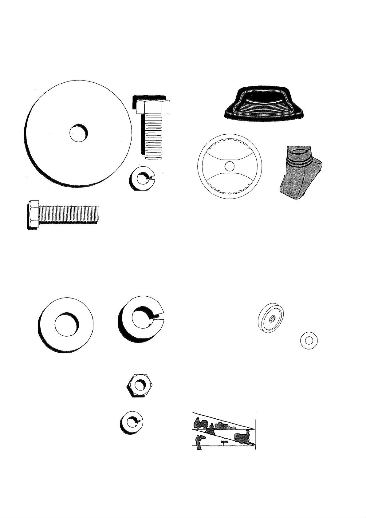
CONTENTS OF HARDWARE PACK
Parts Bag contents shown full size
(1) Hex Bolt
3/8-16 X 1
(1) Large Flat Washer
'' ' ^ (1) Lockwasher 3/8
(1) Locknut
5/16-18
o
(1) Hex Bolt 5/16-18 X 1-1/4
Parts packed separately in carton
Seat
Steering
Sleeve
Steering Wheel
(1) Shoulder Bolt 5/16-18 (1) Hex Bolt 1/2-13 x 1
(1) Lock Washer 1/2
(1) Washer 17/32 x 1-3/16 x 12 Gauge
(2) Hex Bolts 1/4-20 x 3/4
(2) Hex Nuts 1/4-20
(2) Lock Washers 1/4
Manual
Parts Bag
Parts bag contents not shown full size
(2) Shoulder Bolts
(2) Washers 17/32
X 15/16 X 12 Gauge
Steering
i ^ I Ipgg^
Wheel
(2) Gauge
Wheels
0
Steering
Extension
Shaft
o
(2) Center-
lock Nuts
(2) Washers 3/8
X 7/8 X 14 Gauge
—1 —,3—
Steering Wheel
Adapter
(2) Washers 9/32 x 5/8 x 16 Gauge
(2) Keys
Slope Sheet
Page 6
ASSEMBLY
Your new tractor has been assembled at the factory with exception of those parts left unassembled for shipping purposes.
To ensure safe and proper operation of your tractor all parts and hardware you assemble must be tightened securely. Use
the correct tools as necessary to insure proper tightness.
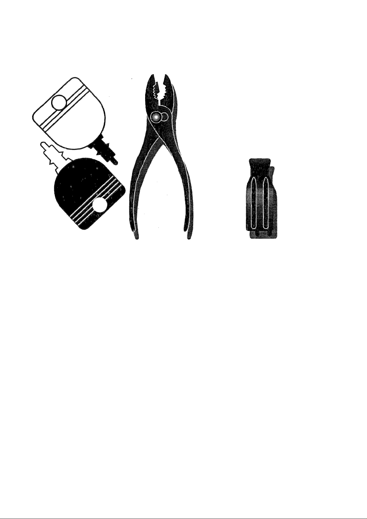
TOOLS REQUIRED FOR ASSEMBLY
A socket wrench set will make assembly easier. Standard
wrench sizes are listed.
(1) 3/4“ Socket w/drive rächet
(2) 7/16" wrenches
(2) 1/2" wrenches
(1) 9/16" wrench
When right or left hand is mentioned in this manual, it
means when you are in the operating position (seated
behind the steering wheel).
TO REMOVE TRACTOR FROM CARTON
UNPACK CARTON
• Remove all accessible loose parts and parts cartons
from carton (See page 5).
• Cut, from top to bottom, along lines on all four corners
of carton, and lay panels flat.
• Check for any additional loose parts or cartons and
remove.
Utility knife
Tire pressure gauge
BEFORE ROLLING TRACTOR OFF SKID
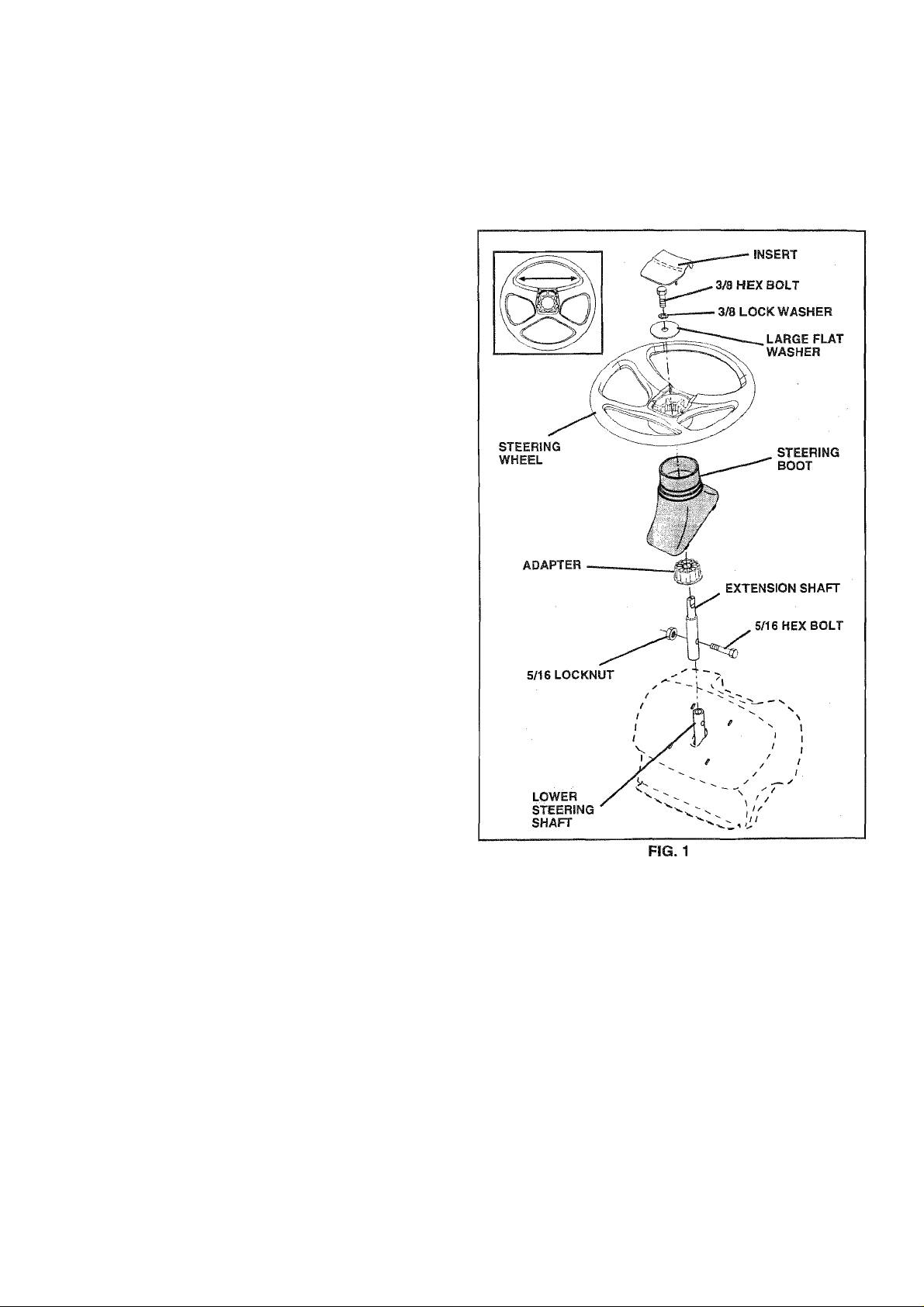
ATTACH STEERING WHEEL (See Fig. 1)
ASSEMBLE EXTENSION SHAFT AND BOOT
• Slide extension shaft onto lower steering shaft. Align
mounting holes in extension and lower shafts and
install 5/16 hex bolt and locknut. Tighten securely.
IMPORTANT; TIGHTEN BOLT AND NUT SECURELY TO
18-22 FT. LBS TORQUE.
• Place tabs of steering boot over tab slots in dash and
push down to secure.
INSTALL STEERING WHEEL
• Position front wheels of the tractor so they are pointing
straight forward.
• Slide steering wheel adapter onto steering shaft exten
sion.
• Position steering wheel so cross bars are horizontal
(left to right) and slide inside boot and onto adapter.
• Assemble large flat washer, 3/8 lock washer, 3/8 hex
bolt and tighten securely.
• Snap steering wheel insert into center of steering
wheel.
• Remove protective materials from tractor hood and
grill.
IMPORTANT: CHECK FOR AND REMOVE ANY STAPLES
IN SKID THAT MAY PUNCTURE TIRES WHERE TRACTOR
IS TO ROLL OFF SKID.
TO ROLL TRACTOR OFF SKID (See Opera
tion section for location and function of con
trols)
• Press lift lever plunger and raise attachment lift (ever to
its highest position.
• Release parking brake by depressing clutch/brake
pedal.
• Place freewheel control in freewheeling position to
disengage transmission (See “TO TRANSPORT in
the Operation section of this manual).
• Roll tractor backwards off skid.
• Remove banding holding discharge guard up against
tractor.
Page 7
ASSEMBLY
HOW TO SET UP YOUR TRACTOR
CONNECT BATTERY (See Figs. 2 and 3)
CAUTION: Do not short battery termi
nals by allowing a wrench or any other
A
object to contact both terminals at the
same time. Before connecting battery,
remove metal bracelets, wristwatch
bands, rings, etc.
Positive terminal must be connected
first to prevent sparking from acciden
tal grounding.
• Remove cardboard packing from seat pan and lift seat
pan to raised position,
• Open battery box door.
• Remove terminal protective caps and discard.
• If this battery is put into service after month and year
indicated on label (label located between terminals)
charge battery for minimum of one hour at 6-tO amps.
• First connect RED battery cable to positive (+) terminal
with hex bolt, flat washer, lock washer and hex nut as
shown. Tighten securely.
• Connect BLACK grounding cable to negative (-) termi
nal with remaining hex bolt, flat washer, lock washer
and hex nut. Tighten securely.
• Close battery box door.
Open battery box door for:
• Inspection for secure connections (to tighten hard
ware).
• Inspection for corrosion.
• Testing battery.
• Jumping (if required).
• Periodic charging .
DISCARD TERMINAL
PROTECTIVE CAPS
BATTERY
BOX DOOR
RG.3
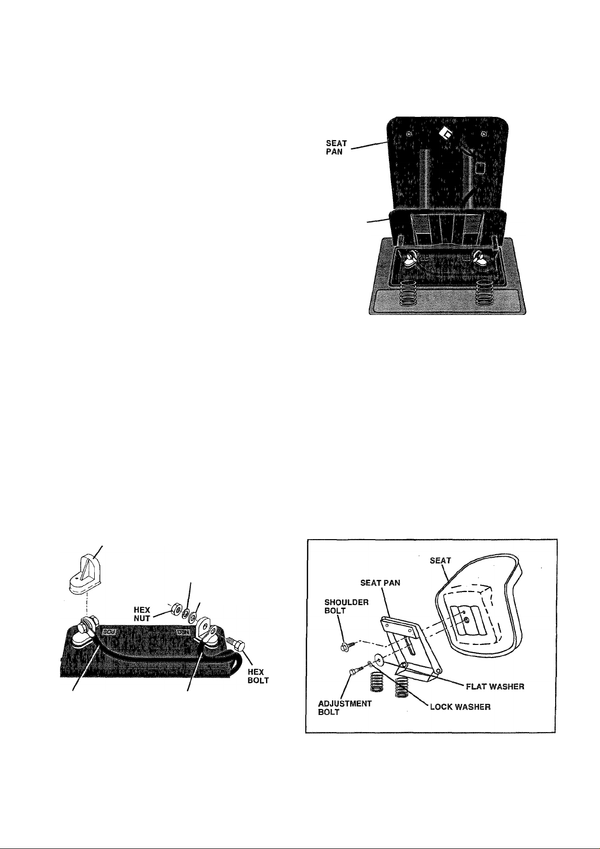
INSTALL SEAT (See Fig. 4)
Adjust seat before tightening adjustment bolt.
• Remove cardboard packing on seat pan.
• Place seat on seat pan and assemble shoulder
bolt.Tighten shoulder bolt securely.
• Assemble adjustment bolt, lock washer and flat washer
loosely. Do not tighten.
• Lower seat into operating position and sit on seat.
• Slide seat until a comfortable position is reached which
allows you to press clutch/brake pedal all the way
down.
• Get off seat without moving its adjusted position.
• Raise seat and tighten adjustment bolt securely.
POSITIVE
(RED) CABLE
LOCK
WASHER
FLAT
WASHER
NEGATIVE
(BLACK) CABLE
FIG. 2
FIG. 4
Page 8
ASSEMBLY
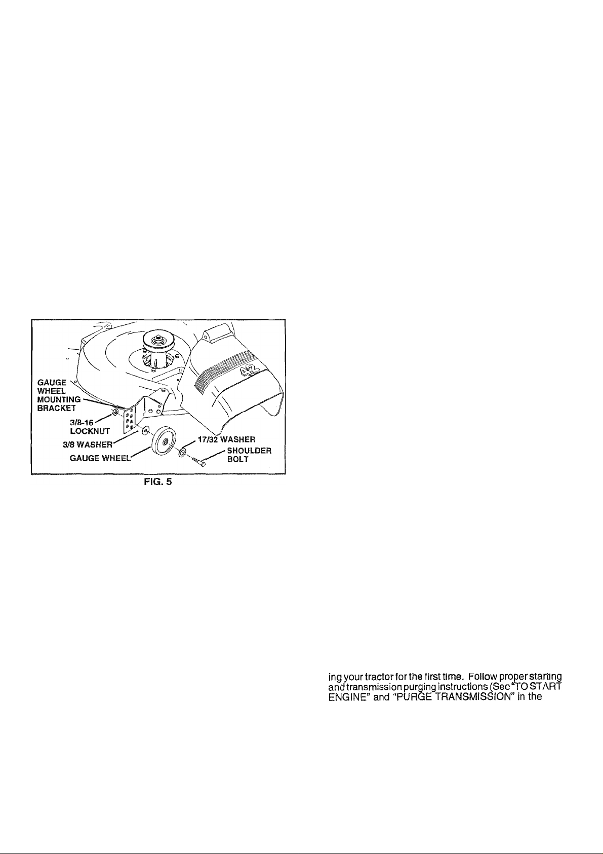
ASSEMBLE GAUGE WHEELS TO MOWER
DECK (See Fig. 5)
The gauge wheels are designed to keep the mower deck in
proper position when operating mower. Be sure they are
properly adjusted to ensure optimum mower performance.
• Assemble gauge wheels with tractor on a flat level
surface.
• Adjust mower to desired cutting height (See ‘TO AD
JUST MOWER CUTTING HEIGHT in the Operation
section of this manual).
• With mower in desired height of cut position, gauge
wheels should be assembled so they are slightly off the
ground. Install gauge wheel in appropriate hole with
shoulder bolt, 17/32 washer, 3/8 washer, and 3/8-16
' locknut and tighten securely.
• Repeat for opposite side installing gauge wheel in
same adjustment hole.
CHECK TIRE PRESSURE
The tires on your tractor were overinflated at the factory for
shipping purposes. Correct tire pressure is important for
best cutting performance.
• Reduce tire pressure to PSI shown in “PRODUCT
SPECIFICATIONS” on page 3 of this manual.
CHECK DECK LEVELNESS
For best cutting results, mower housing should be properly
leveled. See TO LEVEL MOWER HOUSING” in the
Service and Adjustments section of this manual.
CHECK FOR PROPER POSITION OF ALL
BELTS
See the figures that are shown for replacing motion and
mower blade drive belts in the Service and Adjustments
section of this manual. Verify that the belts are routed
correctly.
CHECK BRAKE SYSTEM
After you learn how to operate your tractor, check to see
that the brake is properly adjusted. See TO ADJUST
BRAKE" in the Service and Adjustments section of this
manual.
^CHECKLIST
BEFORE YOU OPERATE AND ENJOY YOUR NEW
TRACTOR, WE WISH TOASSURE THAT YOU RECEIVE
THE BEST PERFORMANCE AND SA TISFACTION FROM
THIS QUALITY PRODUCT.
PLEASE REVIEW THE FOLLOWING CHECKLIST:
/ All assembly instructions have been completed.
/ No remaining loose parts in carton.
/ Battery is properly prepared and charged. (Minimum
1 hour at 6 amps).
/ Seat is adjusted comfortably and tightened securely.
/ All tires are properly inflated. (For shipping purposes,
the tires were overinflated at the factory).
/ Be sure mower deck is properly leveled side-to-side/
front-to-rear for best cutting results. (Tires must be
properly inflated for leveling).
/ Check mower and drive belts. Be sure they are routed
properly around pulleys and inside all belt keepers.
/ Check wiring. See that all connections are still secure
and wires are properly clamped.
/ Before driving tractor, be sure freewheel control is in
drive position.
WHILELEARNING HOWTO USE YOUR TRACTOR, PA Y
EXTRA ATTENTION TO THE FOLLOWING IMPORTANT
ITEMS:
/ Engine oil is at proper level.
/ Fuel tank is filled with fresh, clean, regular unleaded
gasoline.
/ Become familiar with all controls - their location and
function. Operate them before you start the engine.
/ Be sure brake system is in safe operating condition.
/ It is important to purge the transmission before operat-
8
Op-
eration section of this manual).
Page 9

OPERATION
These symbols may appear on your tractor or in literature supplied with the product. Learn and understand their meaning.
a:
Q A
BATTERY
CAUTION OR REVERSE
WARNING
STOP
©
ENGINE ON ENGINE OFF OIL PRESSURE CLUTCH LIGHTS ON OVER TEMP
i
FUEL
l\l mif ^
CHOKE MOWER HEIGHT DIFFERENTIAL PARKING BRAKE UNLOCKED
FORWARD FAST SLOW
a| ©1
LIGHT
LOCK LOCKED
R N H L (®)|I
ÎL
REVERSE NEUTRAL HIGH
I
MOWER LIFT
DANGER, KEEP HANDS AND FEET AWAY
ATTACHMENT
CLUTCH ENGAGED
LOW
ATTACHMENT
CLUTCH DISENGAGED
PARKING BRAKE
0:
IGNITION
....
4-is
HYDROSTATIC FREE WHEEL
(Hydro Models only)
Page 10
OPERATION
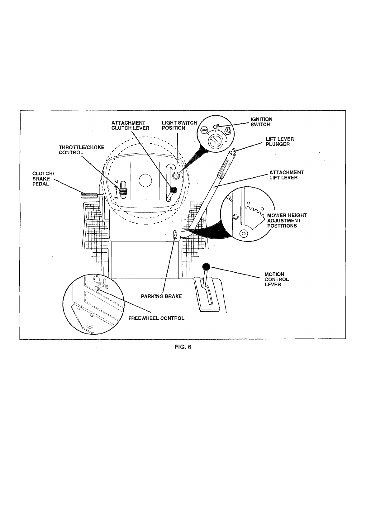
KNOW YOUR TRACTOR
READ THIS OWNER'S MANUAL AND SAFETY RULES BEFORE OPERATING YOUR TRACTOR
Compare the illustrations with your tractor to familiarize yourself with the locations of various controls and adjustments. Save
this manual for future reference.
Our tractors conform to the safety standards of the American National Standards Institute.
ATTACHMENT CLUTCH LEVER: Used to engage the
mower blades, or other attachments mounted to your
tractor.
LIGHT SWITCH: Turns the headlights on and off.
THROTTLE/CHOKE CONTROL - Used for starting and
controlling engine speed.
CLUTCH/BRAKE PEDAL: Used for declutching and
braking the tractor and starting the engine.
PARKING BRAKE: Locks clutch/brake pedal into the
brake position.
MOTION CONTROL LEVER: Selects the speed and
direction of tractor.
ATTACHMENT LIFT LEVER - Used to raise and lower the
mower deck or other attachments mounted to your tractor.
LIFT LEVER PLUNGER: Used to release attachment lift
lever when changing its position.
IGNITION SWITCH: Used for starting and stopping the
engine.
FREEWHEEL CONTROL - Disengages transmission for
pushing or slowly towing the tractor with the engine off.
10
Page 11
OPERATION
The operation of any tractor can result in foreign objects thrown into the eyes, which can
result in severe eye damage. Always wear safety glasses or eye shields while operating
your tractor or performing any adjustments or repairs. We recommend a wide vision
safety mask over the spectacles or standard safety glasses.
HOW TO USE YOUR TRACTOR
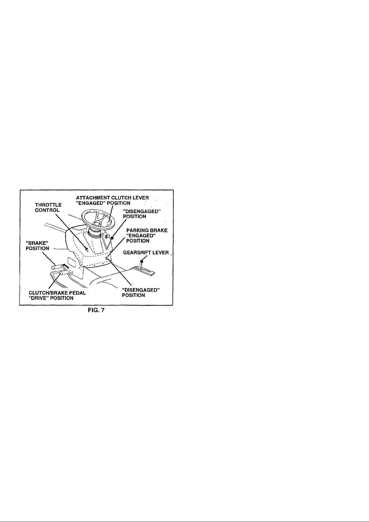
TO SET PARKING BRAKE (See Fig. 7)
Your tractor is equipped with an operator presence sensing
switch. When engine is running, any attempt by the
operator to leave the seat without first setting the parking
brake will shut off the engine.
• Depress clutch/brake pedal into full “BRAKE” position
and hold.
• Place parking brake lever in “ENGAGED” position and
release pressure from clutch/brake pedal. Pedal should
remain in “BRAKE” position. Make sure parking brake
will hold tractor secure.
STOPPING (See Fig. 7J
MOWER BLADES -
• Move attachment clutch lever to “DISENGAGED” po
sition.
GROUND DRIVE -
• Depress clutch/brake pedal into full “BRAKE” position.
• Move motion control lever to neutral (N) position.
IMPORTANT: THE MOTION CONTROL LEVER DOES
NOT RETURN TO NEUTRAL (N) POSITION WHEN THE
CLUTCH/BRAKE PEDAL IS DEPRESSED.
ENGINE-
• Move throttle control to slow position.
NOTE: Failure to move throttle control to slow position and
allowing engine to idle before stopping may cause engine
to “backfire”.
• Turn ignition key to “OFF” position and remove key.
Always remove key when leaving tractor to prevent
unauthorized use.
• Never use choke to stop engine.
NOTE: Under certain conditions when tractor is standing
Idle with the engine running, hot engine exhaust gases may
cause “browning” of grass. To eliminate this possibility,
always stop engine when stopping tractor on grass areas.
CAUTION: Always stop tractor com
pletely, as describe above, before leav
A
ing the operator's position; to empty
grass catcher, etc.
TO USE THROTTLE CONTROL (See Fig. 7)
Always operate engine at full throttle.
• Operating engine at less than full throttle reduces the
battery charging rate.
• Full throttle offers the best bagging and mower perfor
mance.
TO MOVE FORWARD AND BACKWARD
(See Fig. 7)
The direction and speed of movement is controlled by the
motion control lever.
• Start tractor with motion control lever in neutral (N)
position.
• Release parking brake and clutch/brake pedal.
• Slowly move motion control lever to desired position.
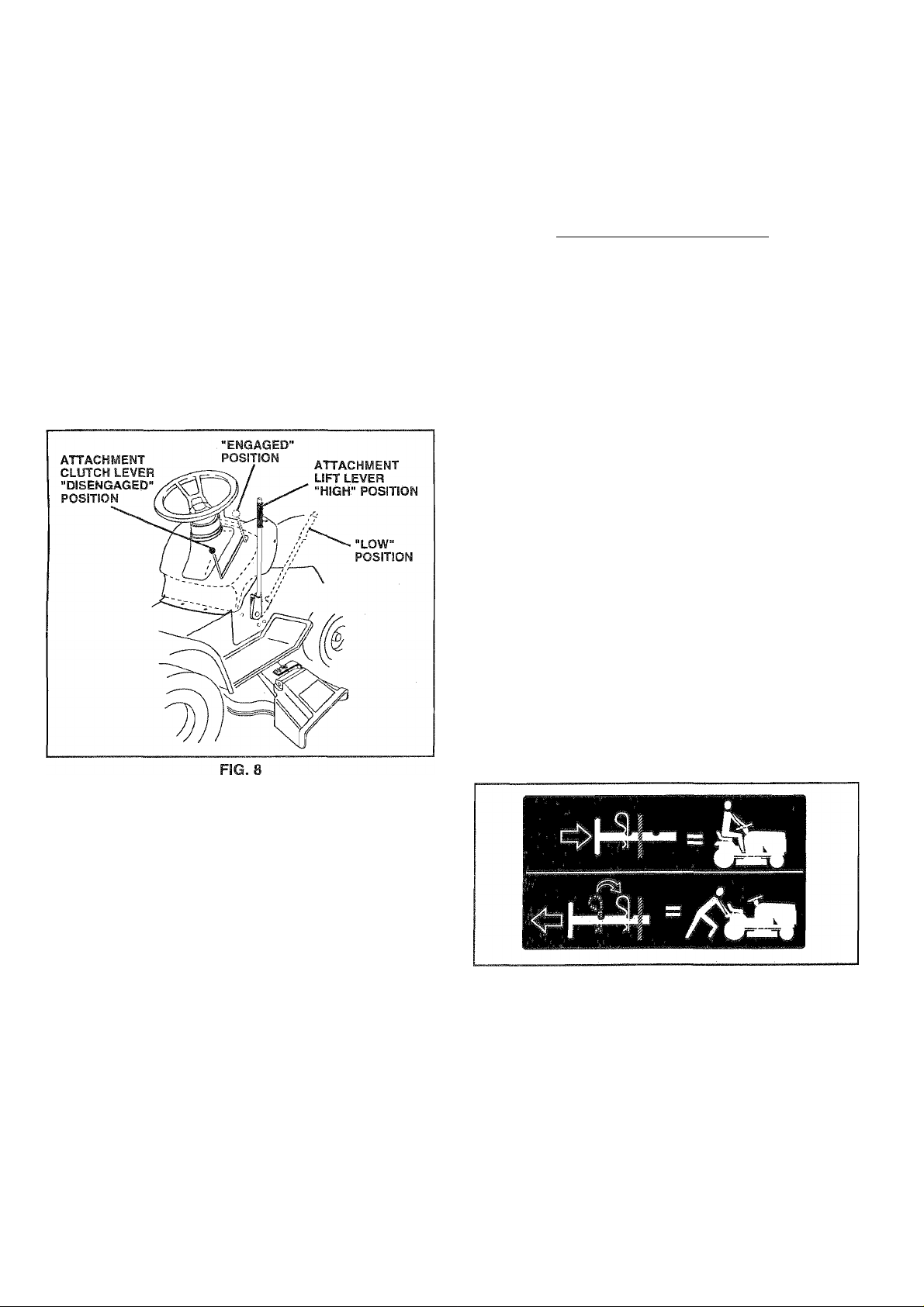
TO ADJUST MOWER CUTTING HEIGHT
(See Fig. 6)
The position of the attachment lift lever determines the
cutting height.
• Grasp lift lever.
• Press plunger with thumb and move lever to desired
position.
The cutting height range is approximately 1 -1/2 to 4". The
heights are measured from the ground to the blade tip with
the engine not running. These heights are approximate
and may vary depending upon soil conditions, height of
grass and types of grass being mowed.
• The average lawn should be cut to approximately 2-1/2
inches during the cool season and to over 3 inches
during hot months. For healthier and better looking
lawns, mow often and after moderate growth.
• For best cutting performance, grass over 6 inches in
height should be mowed twice. Make the first cut
relatively high; the second to desired height.
11
Page 12
OPERATION
TO OPERATE MOWER (See Fig. 8)
Yourtractor is equipped with an operator presence sensing
switch. Any attempt by the operator to leave the seat with
the engine running and the attachment clutch engaged will
shut off the engine.
• Select desired height of cut.
• Lower mower with attachment lift control.
• Start mower blades by engaging attachment clutch
control.
• TO STOP MOWER BLADES - disengage attachment
clutch control.
CAUTION: Do not operate the mower
without either the entire grass catcher,
on mowers so equipped, or the dis
A
charge guard in place.
TO OPERATE ON HILLS
CAUTION: Do not drive up or down
A
• Choose the slowest speed before starting up or down
hills.
• Avoid stopping or changing speed on hills.
• If slowing is necessary, move throttle control lever to
slower position.
• If stopping is absolutely necessary, push clutch/brake
pedal quickly to brake position and engage parking
brake.
• Move motion control lever to neutral (N) position.
IMPORTANT: THE MOTION CONTROL LEVER DOES
NOT RETURN TO NEUTRAL (N) POSITION WHEN THE
CLUTCH/BRAKE PEDAL IS DEPRESSED.
• To restart movement, slowly release parking brake and
clutch/brake pedal.
• Slowly move motion control lever to slowest setting.
• Make all turns slowly.
hills with slopes greater than 15° and
do not drive across any slope.
TO TRANSPORT (See Figs. 9 and 6 )
When pushing or towing your tractor, be sure to disengage
transmission by placing freewheel control in freewheeling
position. Free wheel control is located at the rear drawbar
of tractor.
• Raise attachment lift to highest position with attach
ment lift control.
• Pull freewheel control knob out and hold in position by
inserting retainer spring into forward hole of control
rod.
• Do not push or tow tractor at more than two (2) MPH.
• To reengage transmission, reverse above procedure.
NOTE: To protect hood from damage when transporting
your tractor on a truck or a trailer, be sure hood is closed
and secured to tractor. Use an appropriate means of tying
hood to tractor (rope, cord, etc.).
12
FIG. 9
Page 13

OPERATION
BEFORE STARTING THE ENGINE
CHECK ENGINE OIL LEVEL (See Fig. 12)
• The engine in your tractor has been shipped, from the
factory, already filled with summer weight oil.
• Check engine oil with tractor on level ground.
• Remove oil fill cap/dipstick and wipe clean, reinsert the
dipstick and screw cap tight, wait for a few seconds,
remove and read oil level. If necessary, add oil until
“FULL” mark on dipstick is reached. Do not overfill.
• For cold weather operation you should change oil for
easier starting (See “OIL VISCOSITY CHART in the
Customer Responsibilities section of this manual).
• To change engine oil, see the Customer Responsibili
ties section in this manual.
ADD GASOLINE
• Fill fuel tank. Use fresh, clean, regular unleaded
gasoline with a minimum of 87 octane. (Use of leaded
gasoline will Increase carbon and lead oxide deposits
and reduce valve life). Do not mix oil with gasoline.
Purchase fuel in quantities that can be used within 30
days to assure fuel freshness.
IMPORTANT: WHEN OPERATING IN TEMPERATURES
BELOW 32°F(0“C), USE FRESH. CLEAN WINTER GRADE
GASOLINE TO HELP INSURE GOOD COLD WEATHER
STARTING.
WARNING: Experience indicates that alcohol blended
fuels (called gasohol or using ethanol or methanol) can
attract moisture which leads to separation and formation of
acids during storage. Acidic gas can darnage the fuel
system of an engine while in storage. To avoid engine
problems, the fuel system should be emptied before stor
age of 30 days or longer. Drain the gas tank, start the
engine and let it run until the fuel lines and carburetor are
empty. Use fresh fuel next season. See Storage Instruc
tions for additional information. Never use engine or
carburetor cleaner products in the fuel tank or permanent
damage may occur.
CAUTION: Fill to bottom of gas tank
filler neck. Do not overfill. Wipe off any
A
spilled oil or fuel. Do not store, spill or
use gasoline near an open flame.
TO START ENGINE (See Fig. 7)
When starting the engine for the first time or if the engine
has run out of fuel, it will take extra cranking time to move
fuel from the tank to the engine.
• Be sure freewheel control is in the transmission en
gaged position.
• Sit on seat in operating position, depress clutch/brake
pedal and set parking brake.
• Place motion control lever in neutral (N) position.
• Move attachment clutch to “DISENGAGED” position.
• Move throttle control to choke position.
Note; Before starting, read the warm and cold starting
procedures below.
• Insert key into ignition and turn key clockwise to “START
position and release key as soon as engine starts. Do
not run starter continuously for more than fifteen sec
onds per minute. If the engine does not start after
several attempts, move throttle control to fast position,
wait a few minutes and try again. If engine still does not
start, move the throttle control back to the choke
position and retry.
WARM WEATHER STARTING (50° F and above)
• When engine starts, move the throttle control to the fast
position.
• The attachments and ground drive can now be used. If
the engine does not accept the load, restart the engine
and allow it to warm up for one minute using the choke
as described above.
COLD WEATHER STARTING ( 50° F and below)
• When engine starts, allow engineto run with the throttle
control in the choke position until the engine runs
roughly, then move throttle control to fast position. This
may require an engine warm-up period from several
seconds to several minutes, depending on the tem
perature.
HYDROSTATIC TRANSMISSION WARM UP
• Before driving the unit in cold weather, the transmis
sion should be warmed up as follows:
• Be sure the tractor is on level ground.
• Place the motion control lever in neutral.
Release the parking brake and let the clutch/brake
slowly return to operating position.
• Allow one minute for transmission to warm up.
This can be done during the engine warm up
period.
• The attachments can also be used during the engine
warm-up period afterthetransmission has been warmed
up.
NOTE: If at a high altitude (above 3000 feet) or in cold
temperatures (below 32 F) the carburetor fuel mixture may
need to be adjusted for best engine performance. See ‘TO
ADJUST CARBURETOR” in the Service and Adjustments
section of this manual.
13
Page 14
OPERATION
PURGE TRANSMISSION
CAUTION: Never engage or disengage
freewheel lever while the engine is run
A
To ensure proper operation and performance, it is recom
mended that the transmission be purged before operating
tractor for the first time. This procedure will remove any
trapped air inside the transmission which may have devel
oped during shipping of your tractor.
IMPORTANT: SHOULD YOURTRANSMISSION REQUIRE
REMOVAL FOR SERVICE OR REPLACEMENT, IT
SHOULD BE PURGED AFTER REINSTALLATION
BEFORE OPERATING THE TRACTOR.
• Place tractor safely on level surface with engine off and
parking brake set.
• Disengage transmission by placing freewheel control
in freewheeling position (See “TO TRANSPORT” in
this section of manual).
• Sitting in the tractor seat, start engine. Afterthe engine
is running, move throttle control to slow position. With
motion control lever in neutral (N) position, slowly
disengage clutch/brake pedal.
• Move motion control lever to full forward position and
hold for five (5) seconds. Move lever to full reverse
position and hold for five (5) seconds. Repeat this
procedure three (3) times.
NOTE; During this procedure there will be no movement of
drive wheels. The air is being removed from hydraulic drive
system.
• Move motion control lever to neutral (N) position. Shut
off engine and set parking brake.
• Engage transmission by placing freewheel control in
driving position (See ‘TO TRANSPORT” in this section
of manual).
• Sitting in the tractor seat, start engine. Afterthe engine
is running, move throttle control to half (1/2) speed.
With motion control lever in neutral (N) position, slowly
disengage clutch/brake pedal.
• Slowly move motion control lever forward, after the
tractor moves approximately five (5) feet, slowly move
motion control lever to reverse position. After the
tractor moves approximately five (5) feet return the
motion control lever to the neutral (N) position. Repeat
this procedure with the motion control lever three (3)
times.
• Your tractor is now purged and now ready for normal
operation.
ning.
MOWING TIPS
• Tire chains cannot be used when the mower housing is
attached to tractor.
• Mower should be properly leveled for best mowing
performance. See TO LEVEL MOWER HOUSING” in
the Service and Adjustments section of this manual.
• The left hand side of mower should be used for trim
ming.
• Drive so that clippings are discharged onto the area
that has been cut. Have the cut area to the right of the
tractor. This will result in a more even distribution of
clippings and more uniform cutting.
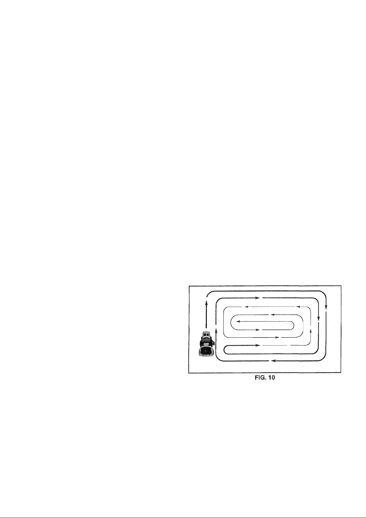
• When mowing large areas, start by turning to the right
so that clippings will discharge away from shrubs,
fences, driveways, etc. After one or two rounds, mow
in the opposite direction making left hand turns until
finished (See Fig. 10).
• If grass is extremely tall, it should be mowed twice to
reduce load and possible fire hazard from dried clip
pings. Make first cut relatively high; the second to the
desired height.
• Do not mow grass when it is wet. Wet grass will plug
mower and leave undesirable clumps. Allow grass to
dry before mowing.
• Always operate engine at full throttle when mowing to
assure better mowing performance and proper dis
charge of material. Regulate ground speed by select
ing a low enough gear to give the mower cutting
performance as well as the quality of cut desired.
• When operating attachments, select a ground speed
that will suit the terrain and give best performance of
the attachment being used.
14
Page 15
CUSTOMER RESPONSIBILITIES
MAINTENANCE SCHEDULE
FILL IN DATES
AS YOU COMPLETE
REGULAR SERVICE
Check Brake Operation
Check Tire Pressure
Check for Loose Fasteners
Shatpen/Replace Mower Blades
Lubrication Chart
Check Battery Level/Recharge
Clean Battery and Terminals
Check Transaxle Cooling
Adjust Blade Belt(s) Tension
Adjust Motion Drive Belt(s) Tension
Check Engine Oil Level
Change Engine Oil
Clean Air Filter
Clean Air Screen
Inspect Muffler/Spark Arrester
Replace Oil Filter (If equipped)
Clean Engine Cooling Fins
Replace Spark Plug
Replace Air Filter Paper Cartridge
Replace Fuel Filter
1 - Change more often when operating under a heavy load or in high ambient temperatures.
2 - Sen/ice more often when operating in dirty or dusty conditions.
3 - If equipped with oil fiiter, change oii every 50 hours.
4 - Replace blades more often when mowing in sandy soil.
✓ ✓
§/
t/
✓
✓
✓ 4
✓ ✓
l/e
✓
✓
✓
1^2,3
✓ 2
✓ 2
✓
SERVICE DATES
✓ 7
✓ 5
✓ s
i^.2
✓
✓
✓
§/"2
✓
✓
✓ 2
✓
5 - If equipped with adjustable system.,
6 - Not required if equipped with maintenance-free battery.
7 - Tighten front axle pivot bolt to 35 fL-lbs. maximum.
Do not overtighten.
GENERAL RECOMMENDATIONS
The warranty on this tractor does not cover items that have
been subjected to operator abuse or negligence. To
receive full value from the warranty, operator must maintain
tractor as instructed in this manual.
Some adjustments will need to be made periodically to
properly maintain your tractor.
All adjustments in the Service and Adjustments section of
this manual should be checked at least once each season.
• Once a year you should replace the spark plug, clean
or replace air filter, and check blades and belts for
wear. A new spark plug and clean air filter assure
proper air-fuel mixture and help your engine run better
and last longer.
BEFORE EACH USE
• Check engine oil level.
• Check brake operation.
• Check tire pressure.
• Check for loose fasteners.
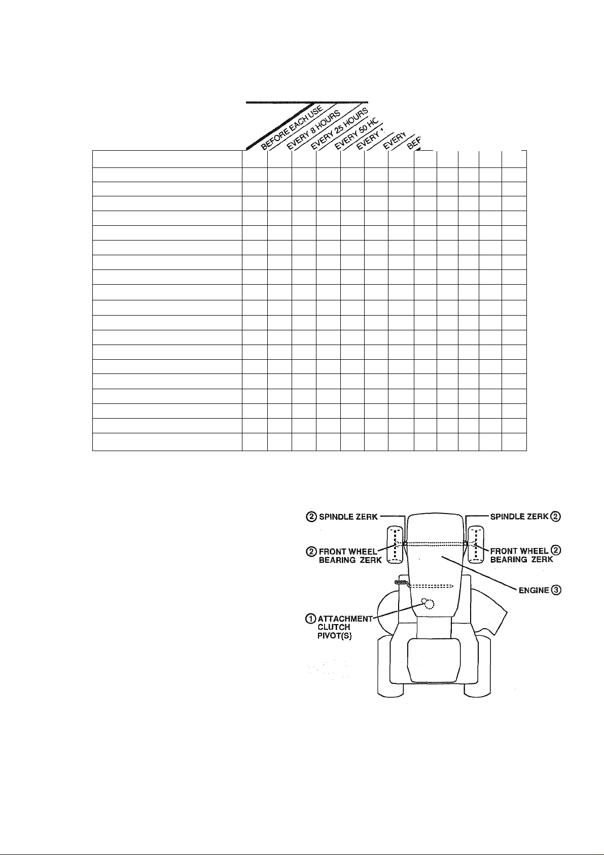
LUBRICATION CHART
0SAE 30 OR 10W30 MOTOR OIL
©GENERAL PURPOSE GREASE
©REFER TO CUSTOMER RESPONSIBILITIES “ENGINE” SECTION
IMPORTANT: DO NOT OIL OR GREASE THE PIVOT POINTS
VVHICH HAVE SPECIAL NYLON BEARINGS. VISCOUS LUBRI
CANTS WILL ATTRACT DUST AND DIRT THAT WILL SHORTEN
THE LIFE OF THE SELF-LUBRICATING BEARINGS. IF YOU
FEEL THEY MUST BE LUBRICATED, USE ONLY A DRY, POW
DERED GRAPHITE TYPE LUBRICANT SPARINGLY.
15
Page 16
CUSTOMER RESPONSIBILITIES
TRACTOR
Always observe safety rules when performing any mainte
nance.
BRAKE OPERATION
If tractor requires more than six (6) feet stopping distance
at high speed in highest gear, then brake must be adjusted.
(See ‘TO ADJUST BRAKE” in the Service and Adjust
ments section of this manual).
TIRES
• Maintain proper air pressure in all tires (See “PROD
UCT SPECIFICATIONS” on page 3 of this manual).
• Keep tires free of gasoline, oil, or insect control chemi
cals which can harm rubber.
• Avoid stumps, stones, deep ruts, sharp objects and
other hazards that may cause tire damage.
NOTE; To seal tire punctures and prevent flat tires due to
slow leaks, tire sealant may be purchased from your local
parts dealer. Tire sealant also prevents tire dry rot and
corrosion.
BLADE CARE
For best results mower blades must be kept sharp. Re
place bent or damaged blades.
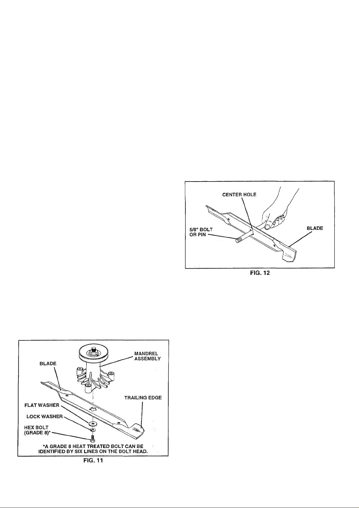
TO SHARPEN BLADE (See Fig. 12)
Care should be taken to keep the blade balanced. An
unbalanced blade will cause excessive vibration and even
tual damage to mower and engine.
• The blade can be sharpened with a file or on a grinding
wheel. Do not attempt to sharpen while on the mower.
• To check blade balance, you will need a 5/8“ diameter
steel bolt, pin, or a cone balancer. (When using a cone
balancer, follow the instructions supplied with bal
ancer).
• Slide blade onto an unthreaded portion of the steel bolt
or pin and hold the bolt or pin parallel with the ground.
If blade is balanced, it should remain in a horizontal
position. If either end of the blade moves downward,
sharpen the heavy end until the blade is balanced.
NOTE: Do not use a nail for balancing blade. The lobes of
the center hole may appear to be centered, but are not.
BLADE REMOVAL (See Fig. 11)
• Raise mower to highest position to allow access to
blades.
• Remove hex bolt, lock washer and flat washer securing
blade.
» Install new or resharpened blade with trailing edge up
towards deck as shown.
• Reassemble hex bolt, lock washer and flat washer in
exact order as shown.
• Tighten bolt securely (30-35 Ft. Lbs. torque).
IMPORTANT: BLADE BOLT IS GRADE 8 HEATTREATED.
NOTE: We do not recommend sharpening blade - but if you
do, be sure the blade is balanced.
BATTERY
Your tractor has a battery charging system which is suffi
cient for normal use. However, periodic charging of the
battery with an automotive charger will extend its life.
• Keep battery and terminals clean.
• Keep battery bolts tight.
• Keep small vent holes open.
• Recharge at 6-10 amperes for 1 hour.
TO CLEAN BATTERY AND TERMINALS
Corrosion and dirt on the battery and terminals can cause
the battery to “leak” power.
• Open battery box door.
• Disconnect BLACK battery cable first then RED bat
tery cable and remove battery from tractor.
• Rinse the battery with plain water and dry.
• Clean terminals and battery cable ends with wire brush
until bright.
• Coat terminals with grease or petroleurti jelly.
• Reinstall battety (See “CONNECT BATTERY" in the
Assembly section of this manual).
16
Page 17

CUSTOMER RESPONSIBILITIES
V-BELTS
Check V-belts for deterioration and wear after 100 hours of
operation and replace if necessary. The belts are not
adjustable. Replace belts if they begin to slip from wear.
TRANSAXLE COOLING
The fan and cooling fins of transmission should be kept
clean to assure proper cooling.
Do not attempt to clean fan or transmission while engine is
running or while the transmission is hot.
• Inspect cooling fan to be sure fan blades are intact and
clean.
• Inspect cooling fins for dirt, grass clippings and other
materials. To prevent damage to seals, do not use
compressed air or high pressure sprayer to clean
cooling fins.
TRANSAXLE PUMP FLUID
The transaxle was sealed at the factory and fluid mainte
nance is not required for the life of the transaxle. Should the
transaxle ever leak or require servicing, contact your near
est authorized service center/department.
ENGINE
LUBRICATION
Only use high quality detergent oil rated with API service
classification SF, SG, or SH. Select the oil’s SAE viscosity
grade according to your expected operating temperature.
TO CHANGE ENGINE OIL (See Fig. 13)
Determine temperature range expected before oil change.
All oil must meet API service classification SF, SG or SH.
• Be sure tractor is on level surface.
• Oil will drain more freely when warm.
• Catch oil in a suitable container.
• Remove oil fill cap/dipstick. Be careful not to allow dirt
to enter the engine when changing oil.
• Remove drain plug.
• After oil has drained completely, replace oil drain plug
and tighten securely.
• Refill engine with oil through oil fill dipstick tube. Pour
slowly. Do not overfill. For approximate capacity see
"PRODUCT SPECIFICATIONS" on page 3 of this
manual.
• Use gauge on oil fill cap/dipstickforchecking level. Be
sure dipstick cap is tightened securely for accurate
..........................;“Fr -
reading. Keep oil at “FULL” line on dipstick.
..........................
NOTE: Although multi-viscosity oils (5W30, 10W30 etc.)
improve starting in cold weather, these multi-viscosity oils
will result in increased oil consumption when used above
32°F. Check your engine oil level more frequently to avoid
possible engine damage from running low on oil.
Change the oil after every 50 hours of operation or at least
once a year if the tractor is not used for 50 hours in one year.
Check the crankcase oil level before starting the engine
and after each eight (8) hours of operation. Tighten oil fill
cap/dipstick securely each time you check the oil level.
17
Page 18

CUSTOMER RESPONSIBILITIES
AIR FILTER (See Fig. 14A)
Your engine will not run properly using a dirty air filter.
Clean the foam pre-cleaner after every 25 hours of opera
tion or every season. Service paper cartridge every 100
hours of operation or every season, whichever occurs first.
Service air cleaner more often under dusty conditions.
• Remove knob(s) and cover.
TO SERVICE PRE-CLEANER
• Slide foam pre-cleaner off cartridge.
• Wash it in liquid detergent and water.
• Squeeze it dry in a clean cloth.
• Saturate it in engine oil. Wrap it in clean, absorbent
cloth and squeeze to remove excess oil.
• If very dirty or damaged, replace pre-cleaner.
• Reinstall pre-cleaner over cartridge.
• Reinstall cover and secure with knob(s).
TO SERVICE CARTRIDGE
• Remove cartridge nut.
• Carefully remove cartridge to prevent debris from en
tering carburetor. Clean base carefully to prevent
debris from entering carburetor.
• Clean cartridge by tapping gently on fiat surface. If very
dirty or damaged, replace cartridge.
• Reinstall cartridge, nut, precleaner, cover and secure
with knob(s).
IMPORTANT: PETROLEUM SOLVENTS, SUCH AS
KEROSENE, ARE NOT TO BE USED TO CLEAN THE
CARTRIDGE. THEY MAY CAUSE DETERIORATION OF
THE CARTRIDGE. DO NOT OIL CARTRIDGE. DO NOT
USE PRESSURIZED AIR TO CLEAN OR DRY
CARTRIDGE.
ENGINE OIL FILTER (See Fig. 14B)
Replace the engine oil filter every season or every other oil
change if the tractor is used more than 100 hours in one
year.
• Unscrew old fiiter by turning counterclockwise. Use a
suitable container to catch oil.
• Apply a thin coating of new engine oil to rubber gasket
on replacement oil filter.
• Install replacement oil filter by turning clockwise until
rubber gasket contacts mounting surface, then tighten
filter an additional 1/2 to 3/4 turn.
• Fill crankcase with new oil (See “TO CHANGE EN
GINE OIL” in this section of this manual). For approxi
mate capacity see “PRODUCT SPECIFICATIONS” on
page 3 of this manual.
• Start engine and check for oil leaks. Correct any leaks
before placing engine into full operation.
ENGINE COOLING FINS (See Fig. 15)
Remove any dust, dirt or oil from engine cooling fins to
prevent engine damage from overheating.
• Remove screws from blower housing and lift housing
and dipstick tube assembly off engine.
• Cover oil fill opening to prevent entry of dirt.
• Use compressed air or stiff bristle brush to thoroughly
clean engine cooling fins.
CLEAN AIR SCREEN (See Fig. 14A)
Air screen must be kept free of dirt and chaff to prevent
engine damage from overheating. Clean with a wire brush
or compressed air to remove dirt and stubborn dried gum
fibers.
18
FIG. 15
Page 19

CUSTOMER RESPONSIBILITIES
MUFFLER
Inspect and replace corroded muffler and spark arrester (if
equipped) as it could create a fire hazard arld/or damage.
SPARK PLUGS
Replace spark plugs at the beginning of each mowing
season or after every 100 hours of operation, whichever
occurs first. Spark plug type and gap setting are shown in
“PRODUCT SPECIFICATIONS” on page 2 of this manual.
IN-LINE FUEL FILTER (See Fig. 16)
The fuel filter should be replaced once each season. If fuel
filter becomes clogged, obstructing fuel flow to carburetor,
replacement is required.
• With engine cool, remove filter and plug fuel line
sections.
» Place new fuel filter in position in fuel line with arrow
pointing towards carburetor.
» Be sure there are no fuel line leaks and clamps are
properly positioned.
• Immediately wipe up any spilled gasoline.
CLEANING
• Clean engine, battery, seat, finish, etc. of all foreign
matter.
• Keep finished surfaces and wheels free of all gasoline,
oil, etc.
• Protect painted surfaces with automotive type wax.
We do not recommend using a garden hose to clean your
tractor unless the electrical system, muffler, air filter and
carburetor are covered to keep water out. Water in engine
can result in a shortened engine life.
19
Page 20

SERVICE AND ADJUSTMENTS
CAUTION: BEFORE PERFORMINC3 ANY SERVICE OR ADJUSTMENTS:
• Depress clufch/brake pedal fully and set parking brake.
• Place motion control lever In neutral (N) position.
A
TRACTOR
TO REMOVE MOWER (See Fig. 17)
Mower will be easier to remove from the right side of tractor.
• Place attachment clutch in “DISENGAGED” position.
• Move attachment lift leverforward to lower mowerto its
lowest position.
• Roll belt off engine pulley.
• Disconnect clutch rod from dutch lever by removing
retainer spring.
• Disconnect anti-sway bar from chassis bracket by
removing retainer spring.
• Disconnect suspension arms from rear deck brackets
by removing retainer springs.
• Disconnect front links from deck by removing retainer
springs.
• Raise lift lever to raise suspension arms. Slide mower
out from under tractor.
IMPORTANT; IF AN ATTACHMENT OTHER THAN THE
MOWER IS TO BE MOUNTED TO THE TRACTOR, THE
R.H. AND LH. SUSPENSION ARMS MUST BE REMOVED
FROM TRACTOR.
TO INSTALL MOWER (See Fig. 17)
• Raise attachment lift lever to its highest position.
• Slide mower u nder tractor with discharge guard to right
side of tractor.
• Lower lift lever to its lowest position.
• Install mower in reverse order of removal instructions.
• Place attachment clutch in “DISENGAGED” position.
• Turn ignition key “OFF” and remove key.
• Make sure the blades and ail moving parts have completely stopped.
• Disconnect spark plug wire from spark plug and place wire where it cannot come in contact
with plug.
RETAINER
SPRINGS
(BOTH SIDES)
RETAINER
SPRINGS
(BOTH SIDES)
FIG. 17
20
Page 21

SERVICE AND ADJUSTMENTS
TO LEVEL POWER HOUSING
Adjust the mower while tractor is parked on level ground or
driveway. Make sure tires are properly inflated (See
“PRODUCT SPECIFICATIONS” on page 2 of this manual).
If tires are over or underinflated, you will not properly adjust
your mower.
SIDE-TO-SIDE ADJUSTMENT (See Figs. 18 and 19)
• Raise mower to its highest position.
• At the midpoint of both sides of mower, measure height
from bottom edge of mowerto ground. Distance “A” on
both sides of mower should be the same or within 1/4"
of each other.
• If adjustment is necessary, make adjustment on one
side of mower only.
• To raise one side of mower, tighten lift link adjustment
nut on that side.
• To lower one side of mower, loosen lift link adjustment
nut on that side.
NOTE: Three full turns of adjustment nut will change
mower height about 1/8“.
• Recheck measurements after adjusting.
FRONT-TO-BACK ADJUSTMENT (See Figs. 20 and 21)
IMPORTANT: DECK MUST BE LEVEL SIDE-TO-SIDE. IF
THE FOLLOWING FRONT-TO-BACK ADJUSTMENT IS
NECESSARY, BE SURE TO ADJUST BOTH FRONT LINKS
EQUALLY SO MOWER WILL STAY LEVEL SIDE-TOSIDE.
To obtain the best cutting results, the mower housing
should be adjusted so that the front is approximately 1 /8" to
1/2“ lower than the rear when the mower is in its highest
position.
Check adjustment on right side of tractor. Measure dis
tance “D” directly in front and behind the mandrel at bottom
edge of mower housing as shown.
• Before making any necessary adjustments, check that
both front links are equal in length. Both links should be
approximately 10-3/8".
• If links are not equal in length, adjust one link to same
length as other link.
• To lower front of mower loosen nut “E” on both front
links an equal number of turns.
• When distance “D” is 1/8“ to 1/2“ lower at front than
rear, tighten nuts “P against trunnion on both front
links.
• To raise front of mower, loosen nut “P from trunnion on
both front links. Tighten nut “E” on both front links an
equal number of turns.
• When distance “D” is 1/8" to 1/2" lower at front than
rear, tighten nut “P against trunnion on both front links.
• Recheck side-to-side adjustment.
21
Page 22

SERVICE AND ADJUSTMENTS
TO REPLACE MOWER BLADE DRIVE BELT
(See Fig. 22)
The mower blade drive belt may be replaced without tools.
Park the tractor on level surface. Engage parking brake.
BELT REMOVAL -
• Remove mower from tractor (See ‘TO REMOVE
MOWER” in this section of this manual).
• Work belt off both mandrel pulleys and idler pulleys.
• Pull belt away from mower.
BELT INSTALLATION -
• Install new belt in reverse order of removal.
• Make sure belt is in all pulley grooves and inside all belt
guides.
• Install mower in reverse order of removal instructions.
TO ADJUST BRAKE (See Fig. 23)
Your tractor is equipped with an adjustable brake system
which is mounted on the side of the transaxle.
If tractor requires more than six (6) feet stopping distance
at high speed in highest gear, then brake must be adjusted.
• Depress clutch/brake pedal and engage parking brake.
• Measure distance between brake operating arm and
nut “A” on brake rod.
• If distance is other than 1-3/4", loosen jam nut and turn
nut “A” until distance becomes 1-3/4". Retighten jam
nut against nut “A”.
• Road test tractorfor proper stopping distance as stated
above. Readjust if necessary. If stopping distance is
still greater than six (6) feet in highest gear, further
maintenance is necessary. Contact your nearest au
thorized sen/ice center/department.
WITH PARKING BRAKE “ENGAGED”
DO NOT TOUCH THIS NUT. IF FURTHER
BRAKE ADJUSTMENT IS NECESSARY
CONTACT YOUR NEAREST AUTHORIZED
SERVICE CENTER/DEPARTMENT
FIG. 23
TO REPLACE MOTION DRIVE BELT
(See Fig. 24)
Park the tractor on level surface. Engage parking brake.
For assistance, there is a belt installation guide decal on
bottom side of left footrest.
• Remove mower (See ‘TO REMOVE MOWER” in this
section of this manual.)
• Remove upper belt keeper.
• Remove belt from stationary idler and clutching idler.
• Pull belt slack toward rear of tractor. Carefully remove
belt upwards from transmission input pulley and over
cooling fan blades.
• Pull belt toward front of tractor and remove downward
from around engine pulley.
• Install new belt by reversing above procedure.
IMPORTANT: MAKE SURE UPPER BELT KEEPER IS
POSITIONED PROPERLY BETWEEN LOCATOR TAB.
22
FIG. 24
Page 23

SERVICE AND ADJUSTMENTS
TO ADJUST STEERING WHEEL ALIGNMENT
If steering wheel crossbars are not horizontal (left to right)
when wheels are positioned straightforward, remove steer
ing wheel and reassemble per instructions in the Assembly
section of this manual.
FRONT WHEEL TOE-IN/CAMBER
The front wheel toe-in and camber are not adjustable on
your tractor. If damage has occurred to affect the front
wheel toe-in or camber, contact your nearest authorized
service center/departmeht.
TO REMOVE WHEEL FOR REPAIRS
(See Fig. 25)
• Block up axle securely.
• Remove axle cover, retaining ring and washers to allow
wheel removal (rear wheel contains a square key - Do
not lose).
• Repair tire and reassemble.
• On rear wheels only: align grooves in rear wheel hub
and axle. Insert square key.
• Replace washers and snap retaining ring securely in
axle groove.
• Replace axle cover.
NOTE: To seal tire punctures and prevent flat tires due to
slow leaks, tire sealant may be purchased from your local
parts dealer. Tire sealant also prevents tire dry rot and
corrosion.
WASHERS
RETAINING
RING
AXLE COVER
SQUARE KEY
(REAR WHEEL ONLY)
FIG. 25
23
Page 24

SERVICE AND ADJUSTMENTS
TO START ENGINE WITH A WEAK BATTERY
(See Fig. 26)
CAUTION: Lead-acid batteries gener
ate explosive gases. Keep sparks, flame
and smoking materials away from bat
A
If your battery is too weak to start the engine, it should be
recharged. If "jumper cables” are used for emergency
starting, follow this procedure:
IMPORTANT; YOUR TRACTOR IS EQUIPPED WITH A 12
VOLT NEGATIVE GROUNDED SYSTEM. THE OTHER
VEHICLE MUST ALSO BE A 12 VOLT NEGATIVE
GROUNDED SYSTEM. DO NOT USE YOUR TRACTOR
BATTERY TO START OTHER VEHICLES,
TO ATTACH JUMPER CABLES -
• Connect each end of the RED cable to the POSITIVE
(+) terminal of each battery, taking care not to short
against chassis.
• Connect one end of the BLACK cable to the NEGA
TIVE (-) terminal of fully charged battery.
• Connect the other end of the BLACK cable to good
CHASSIS GROUND, away from fuel tank and battery.
TO REMOVE CABLES, REVERSE ORDER -
• BLACK cable first from chassis and then from the fully
charged battery.
• RED cable last from both batteries.
teries. Always wear eye protection
when around batteries.
TO REPLACE HEADLIGHT BULB
• Raise hood.
• Puli bulb holder out of the hole in the backside of the
grill.
• Replace bulb in holder and push bulb holder securely
back into the hole in the backside of the grill.
• Close hood.
INTERLOCKS AND RELAYS
Loose or damaged wiring may cause your tractor to run
poorly, stop running, or prevent it from starting.
• Check wiring. See electrical wiring diagram in the
Repair Parts section of this manual.
TO REPLACE FUSE
Replace with 30 amp automotive-type plug-in fuse. The
fuse holder is located behind the dash.
TO REMOVE HOOD AND GRILL ASSEMBLY
(See Fig. 27)
• Raise hood.
• Unsnap headlight wire connector.
• Stand in front of tractor. Grasp hood at sides, tilt toward
engine and lift off of tractor.
• To replace, reverse above procedure.
POSITIVE TERMINAL NEGATIVE TERMINAL
CHASSIS-
POSITIVE TERMINAL
FIG. 26
NEGATIVE TERMINAL
■ CABLES
CHARGED
BATTERY
24
Page 25

SERVICE AND ADJUSTMENTS
ENGINE
TO ADJUST THROTTLE CONTROL CABLE
(See Fig. XX)
The throttle control has been preset at the factory and
adjustment should not be necessary. Check adjustment as
described below before loosening cable. If adjustment is
necessary, proceed as follows;
• With engine not running* move throttle control lever
from slow to choke position. Slowly move lever from
choke to fast position.
• Check that holes “A” in governor control lever and hole
in governor plate line-up. If holes “A” are not aligned,
loosen clamp screw and move throttle cable until holes
are aligned. Tighten clamp screw securely.
PRELIMINARY SETTING -
• Air cleaner assembly must be assembled to the carbu
retor when making carburetor adjustments.
• Be sure the throttle control cable is adjusted properly
(see above).
FINAL SETTING -
• Start engine and allow to warm for five minutes. Make
final adjustments with engine running and shift/motion
controi lever in neutrai (N) position.
• Move throttle control lever to slow position. With finger,
rotate and hold throttle lever against idle speed screw.
Turn idle speed screw to attain 1750 RPM.
• While still holding throttle lever against idle speed
screw, turn idle mixture valve full travel clockwise then
counterclockwise until engine runs rough. Turn valve
to a point midway between those two positions. Re
lease throttle lever.
ACCELERATION TEST -
• Move throttle control lever from slow to fast position. If
engine hesitates or dies, turn idie mixture vaive out
(counterclockwise) 1 /8 turn. Repeat test and continue
to adjust, if necessary, until engine accelerates
smoothly.
High speed stop is factory adjusted. Do not adjust damage may result.
IMPORTANT: NEVER TAMPER WITH THE ENGINE
GOVERNOR, WHICH IS FACTORY SET FOR PROPER
ENGINE SPEED. OVERSPEEDING THE ENGINE ABOVE
THE FACTORY HIGH SPEED SETTING CAN BE
DANGEROUS. IF YOU THINK THE ENGINE-GOVERNED
HIGH SPEED NEEDS ADJUSTING, CONTACT YOUR
NEAREST AUTHORIZED SERVICE CENTER/
DEPARTMENT, WHICH HAS PROPER EQUIPMENT AND
EXPERIENCE TO MAKE ANY NECESSARY
ADJUSTMENTS.
TO ADJUST CARBURETOR (See Fig. 2B)
NOTE: The carburetor on this engine is low emission. It is
equipped with an idle fuel adjusting needle with a limiter
cap, which allows some adjustment within the limits al
lowed by the cap. Do not attempt to remove the lirhiter cap.
The limiter cap cannot be removed without breaking the
adjusting needle.
The carburetor has been preset at the factory and adjust
ment should not be necessary. However, minor adjust
ment may be required to compensate fordifferences in fuel,
temperature, altitude or load. If the carburetor does need
adjustment, proceed as follows:
In general, turning idle mixture valve in (clockwise) de
creases the supply of fuel to the engine giving a leaner fuel/
air mixture. Turning the idle mixture valve out (counter
clockwise) increases the supply of fuel to the engine giving
a richer fuel/air mixture.
IMPORTANT: DAMAGE TO THE NEEDLE VALVE AND
THE SEAT IN CARBURETOR MAY RESULT IF SCREW IS
TURNED IN TOO TIGHT.
25
Page 26

STORAGE
Immediately prepare your tractor for storage at the end of
the season or if the tractor will not be used for 30 days or
more.
CAUTION: Never store the tractor with
gasoline in the tank inside a building
where fumes may reach an open fiame
A
or spark. Allow the engine to cool
before storing in any enciosure.
TRACTOR
Remove mower from tractor for winter storage. When
mower is to be stored for a period of time, clean it thor
oughly, remove all dirt, grease, leaves, etc. Store In a
clean, dry area.
• Clean entire tractor (See “CLEANING” in the Customer
Responsibilities section of this manual).
• Inspect and replace belts, if necessary (See belt re
placement instructions in the Service and Adjustments
section of this manual).
• Lubricate as shown in the Customer Responsibilities
section of this manual.
• Be sure that all nuts, bolts and screws are securely
fastened. Inspect moving parts for damage, breakage
and wear. Replace if necessary.
• Touch up all rusted or chipped paint surfaces; sand
lightly before painting.
BATTERY
• Fully charge the battery for storage.
• After a period of time in storage, battery may require
recharging.
• To help prevent corrosion and power leakage during
long periods of storage, battery cables should be
disconnected and battery cleaned thoroughly (see ‘TO
CLEAN BATTERY AND TERMINALS” in. the Cu$-;
tomer Responsibilities section of this manual).
• After cleaning,'leave cables disconnected and place
cables where they cannot come in contact with battery
terminals.
• Be sure battery drain tube is securely attached.
• If battery Is removed from tractor for storage, do not
store battery directly on concrete or damp surfaces.
ENGINE
FUEL SYSTEM
IMPORTANT: IT IS IMPORTANT TO PREVENT GUM
DEPOSITS FROM FORMING IN ESSENTIAL FUEL
SYSTEM PARTS SUCH AS CARBURETOR, FUEL FILTER,
FUEL HOSE, OR TANK DURING STORAGE. ALSO,
EXPERIENCE INDICATES THAT ALCOHOL BLENDED
FUELS (CALLED GASOHOL OR USING ETHANOL OR
METHANOL) CAN ATTRACT MOISTURE WHICH LEADS
TO SEPARATION AND FORMATION OF ACIDS DURING
STORAGE. ACIDIC GAS CAN DAMAGE THE FUEL
SYSTEM OF AN ENGINE WHILE IN STORAGE.
« Drain the fuel tank.
• Start the engine and let it run until the fuel lines and
carburetor are empty.
• Never use engine or carburetor cleaner products in the
fuel tank of permanent damage may occur.
• Use fresh fuel next season.
NOTE: Fuel stabilizer is an acceptable alternative in
minimizing the formation of fuel gum deposits during stor
age. Add stabilizer to gasoline in fuel tank or storage
container. Always follow the mix ratio found on stabilizer
container. Run engine at least 10 minutes after adding
stabiIizer to allow the stabiIizer to reach the carburetor. Do
not drain the gas tank and carburetor if using fuel stabilizer.
ENGINE OIL
Drain oil (with engine warm) and replace with clean engine
oil. (See “ENGINE” in the Customer Responsibilities
section of this manual).
CYLINDERS
Remove spark plug(s).
Pour one ounce of oil through spark plug hole(s) into
cylinder(s).
Turnjgnitiqn key to “START position for a few seconds
to distribute oil.
Replace with new spark plug(s).
OTHER
Do not store gasoline from one season to another.
Replace your gasoline can if your can starts to rust.
Rust and/or dirt in your gasoline will cause problems.
If possible, store your tractor indoors and cover it to
give protection from dust and dirt.
Cover your tractor with a suitable protective coverthat
does not retain moisture. Do not use plastic. Plastic
cannot breathe which allows condensation to form and
will cause your tractor to rust.
IMPORTANT: NEVER COVER TRACTOR WHILE ENGINE
AND EXHAUST AREAS ARE STILL WARM.
26
Page 27

TROUBLESHOOTING POINTS
PROBLEM CAUSE CORRECTION
Will not start 1. Otrt of fuel. 1. Fill fuel tank.
Hard to start 1. Dirty air filter.
Engine will not turn over 1. Clutch/brake pedal not depressed.
2. Engine not “CHOKED" property. 2.
3.
Engine flooded.
4. Bad spark plug.
5. Dirty air filter.
6. Dirty fuel filter.
7.
Water in fuel.
Loose or damaged wiring. 8. Check all wiring.
8.
Carburetor out of adjustment.
9.
Engine valves out of adjustment. 10. Contact an authorized service center/department.
10.
2.
Bad spark plug.
3. Weak or dead battery. 3.
4. Dirty fuel filter.
5. Stale or dirty fuel.
6. Loose or damaged wiring.
7.
Carburetor out of adjustment.
8. Engine valves out o1 adjustment.
2. Attachment Clutch is engaged.
Weak or dead battery. 3.
3.
Blown fuse.
.4.
5. Corroded battery terminals.
6. Loose or damaged wiring.
7. Faulty ignition switch.
8. Faulty solenoid or starter.
9. Faulty operator presence switch(es).
See “TO START ENGINE” in Operation section.
3.
Wait several minutes before attempting to start.
4.
Replace spark plug.
5. Clean/replace air filter.
6.
Replace fuel filter.
7.
Drain fuel tank and carburetor, refill tank with fresh
gasoline and replace fuel filter.
9.
See "To Adjust Carburetor” in Service Adjustments
section.
1. Clean/replace air filter.
2. Replace spark plug.
Recharge or replace battery.
4. Replace fuel filter.
5. Drain fuel tank and refill with fresh gasoline.
6. Check all wiring.
7.
See “To Adjust Carburetor” in Service Adjustments
\ section.
8. Contact an authorized service center/department.
1. Depress clutch/brake pedal.
Disengage attachment clutch.
2.
Recharge or replace battery.
4.
Replace fuse.
5.
Clean battery terminals.
6. Check all wiring.
Check/replace ignition switch.
7.
8. Check/replace solenoid or starter.
9.
Contact an authorized service center/department.
Engine clicks but will not 1. Weak or dead battery.
start
Loss of power 1. Cutting too much grass/loo fast. 1. Set in “Higher Cut” position/reduce speed.
Excessive vibration 1,
2.
Corroded battery terminals.
3. Loose or damaged wiring.
4. Faulty solenoid or starter.
2. Throttle in “CHOKE” position.
3.
Build-up of grass, leaves and trash under mower.
4.
Dirty air filter.
5.
Low oil level/dirty oil.
6. Faulty spark plug.
7. Dirty fuel filter. 7. Replace fuel filter;
8. Stale or dirty fuel. 8. Drain fuel tank and refill with fresh gasoline.
9. Water in fuel. 9. Drain fuel tank and carburetor, refill tank with fresh
10. Spark plug wire loose. 10. Connect and tighten spark plug wire;
11.
Dirty engine air screen/fins.
12. Dirty/clogged muffler. 12.
13. Loose or damaged wiring. 13. Check all wiring.
14.
Carburetor out of adjustment.
15.
Engine valves out of adjustment.
Worn, bent or loose blade.
2.
Bent blade mandrel.
3.
Loose/damaged part(s).
1. Recharge or replace battery.
2. Clean battery terminals.
3. Check all wiring.
4.
Check/replace solenoid or starter.
2.
Adjust throttle control.
3. Clean underside of mower housing.
Clean/replace air filter.
4.
5.
Check oil level/change oil.
6.
Clean and regap or change spark plug.
gasoline and replace fuel filter.
Clean engine air screen/fins.
11.
Clean/replace muffler.
14.
See To Adjust Carburetor” in Service Adjustments
section.
15. Contact an authorized service center/department.
1.
Replace blade. Tighten blade bolt.
2.
Replace blade mandrel.
3.
Tighten loose part(s). Replace damaged parts.
27
Page 28

TROUBLESHOOTING POINTS
PROBLEM
Engine continues to run
when operator leaves seat
with attachment clutch
engaged
Poor cut - uneven
Mower blades will not
rotate
Poor grass discharge
CAUSE
1. Faulty operator-safety presence control system.
1. Worn, bent or loose blade.
2. Mower deck not level.
3. Buildup of grass, leaves, and trash under mower.
4. Bent blade mandrel.
5. Clogged mower deck vent holes from buildup of
grass, leaves, and trash around mandrels.
1. Obstnjction In clutch mechanism.
2. Wom/damaged mower drive belt.
3. Frozen idler pulley.
4. Frozen blade mandrel.
1. Engine speed too slow.
2. Travel speed too fast.
3. Wet grass.
4. Mower deck not level.
5. Low/uneven tire air pressure.
6. Worn, bent or loose blade.
7. Buildup of grass, leaves and trash under mower.
8. Mower drive belt worn.
9. Blades improperly installed,
to. improper blades used.
11. Clogged mower deck vent holes from buildup of
grass, leaves, and trash around mandrels.
CORRECTION
1. Check wiring, switches and connections. If not
corrected, contact an authorized service center/
department.
1. Replace blade. Tighten blade bolt.
2. Level mower deck.
3. Clean underside of mower housing.
4. Replace blade mandrel.
5. Clean around mandrels to open vent holes.
1. Remove obstruction.
2. Replace mower drive belt.
3. Replace idler pulley.
4. Replace blade mandrel.
1. Place throttle control in “FAST position.
2. Shift to slower speed.
3. Allow grass to dry before mowing.
4. Level mower deck.
5. Check tires for proper air pressure.
6. Replace/sharpen blade. Tighten blade bolt.
7. Clean underside of mower housing.
8; Replace mower drive belt.
9. Reinstall blades sharp edge down.
10. Replace with blades listed in this manual.
11. Clean around mandrels to open vent holes.
Headlight(s) not working
(if so equipped]
1. Switch Is “OFF”.
2. Buib(s) burned out.
3. Faulty light switch.
4. Loose or damaged wiring.
5. Blown fuse.
Battery will not charge
1. Bad battery cell(s).
2. Poor cable connections.
3. Faulty regulator (if so equipped).
4. Faulty alternator.
Loss of drive 1. Freewheel control in “disengaged" position.
2. Motion drive belt worn, damaged, or broken.
3. Air trapped in transmission during shipment
or servicing.
Engine “backfires”
when turning engine
1. Engine throttle control not set at “SLOW”
position for 30 seconds before stopping engine.
“OFF”
1. Turn switch “ON”.
2. Replace bulb(s).
3. Check/rèplace light switch.
4. Check wiring and connections.
5. Replace fuse.
1. Replace battery.
2. Check/clean all connections.
3. Replace regulator.
4. Replace alternator.
1. Place freewheel control in "engaged” position.
2. Replace motion drive belt.
3. Purge transmission.
1. Move throttle control to “SLOW” position and allow
to Idle for 30 seconds before stopping engine.
28
Page 29

SCHEMATIC
TRACTOR - - MODEL NUMBER HD145H42H
BLACK
IGNITION SWITCH
POSITION
OFF
RUN/LIGHT
RUN
START
CIRCUIT “MAKE”
G + M + L NONE
B + L+S
B + L
B + L
A + Y
NONE
NONE
NOTE
YOUR TRACTOR IS
EQUIPPED WITH A SPECIAL
ALTERNATOR SYSTEM.
THE LIGHTS ARE NOT
CONNECTED TO THE
BATTERY. BUT HAVE THEIR
L0-J
OWN ELECTRICAL SOURCE.
BECAUSE OF THIS, THE
HEADLIGHTS
BRIGHTNESS OF THE LIGHTS
WILL CHANGE WITH ENGINE
SPEED. AT IDLE THE LIGHTS
WILL DIM. AS THE ENGINE IS
SPEEDED UP, THE LIGHTS
WILL BECOME THEIR BRIGHTEST,
NON-REMOVABLE
CONNECTIONS
CONNECTIONS
WIRING INSULATED CLIPS
NOTE: IF WIRING INSULATED CLIPS WERE REMOVED FOR
SERVICING OF UNIT, THEY SHOULD BE REPLACED TO
PROPERLY SECURE YOUR WIRING.
29
BUCK I
rh
REMOVABLE
Page 30

REPAIR PARTS
ELECTRICAL
TRACTOR - - MODEL NUMBER HD145H42H
Page 31

REPAIR PARTS
ELECTRICAL
TRACTOR - - MODEL NUMBER HD145H42H
KEY PART
NO. NO. DESCRIPTION
1 144925 Battery 12 Volt 25 Amp
74760412
2
3 19091016 Washer 9/32 X 5/8 X 16 Ga
10040400
4
6 73220400 Nut Fin Hex 1/4-20 Unc
156417
8
153664
16
10090400
19
73350400 Nut Jam Hex 1/4-20 Unc
20
136850
21
22 4152J
4799J
24
146147'
25
108824X
26
4207J
28
121305X
29
140301 Switch Ign 4 Pos W/L P/L
30
31 12421IX
141226
32
122147X
33
40 156442
41
71110408
42 131563 Cover Terminal Red
43 145673 Solenoid
44 73640400
48 140844
52 141940 Protection Loop
140422 Harness Eng B&S 14 OHV Dual
70
Bolt Hex Hd 1/4-20unc X 3/4
Washer Lock Hvy Helical 1/4
Case Battery Mech Hinge
Switch Interlock Push-In
Washer Lock 1/4
Harness Socket Light
Bulb, Light # 1156
Cable Starter 6ga 11" Bed
Cable Battery 6 Ga Red w/16 wire
Fuse 30 Amp Auto Green
Cable Ground 6ga 12"black
Switch Plunger Nc Gray
Nut Ignition
Cover Sw Key
Key Ign Molded Generic
Harness Ign
Bolt Fin Hex 1/4-20uncx 1/2
Nut Keps BIk Fin Hex 1/4-20 Unc x 1/2
Adapter Ammeter Rectangular
NOTE: All component dimensions given in U.S. inches
1 inch = 25.4 mm
31
Page 32

REPAIR PARTS
TRACTOR - - MODEL NUMBER HD145H42H
CHASSIS AND ENCLOSURES
32
Page 33

REPAIR PARTS
TRACTOR - - ^ODEL NUMBER HD145H42H
CHASSIS AND ENCLOSURES
KEY
NO.
10
11 155927 Panel Asm. Dash Lh
12
13
14 17490608
15
16
17 159639X428
18 126938X
20 156437 Plate Mtg Battery/Fuel Tank
23 124028X
24 74780616 Bolt Fin Hex 3/8-16 Unc x 1 Gr. 5
25 19131312
26 73800600
28 157373 Grill Private Lable BIk
29 140273
30 157583X428 Fender Asm LT w/Shift MS-428
31 136619 Bracket Fender
33
34 105475X428 Footrest Pnt. Rh Ms-428
35 72110606 Bolt RdHd Sht. Sqnk. 3/8-16x 3/4
37
38 139886 Bracket Asm. Pvt. Lh Mwr. Rear
39 139887 Bracket Asm. Pvt. Rh Mwr. Rear
51
52 19091416 Washer 9/32 x 7/8 x 16 Ga.
53 144697 Bracket Grille LH
54 161464
55
57 74780412
58 150127 Air Duct Private Label
140
145
NOTE: All component dimensions given in U.S. inches
PART
NO.
1 160393 Chassis WIdmt.
2 140356
3 17490612 Screw Thdrol. 3/8-16 x 3/4Ty-Tt
4 19131216
5 155272
6 155923 Saddle Fender Shift Flat
8 155138
161937X011 Dash Private Label
9
72140608 Bolt RdHd Sqnk. 3/8-16 Line x 1
145660
155934X010
74180512 Screw Mach Trhd 5/16-18 Unc x 3/4
73510500 Nut Keps 5/16-18 Unc
105476X428
17490508
73800400 Nut Lock Hex W/lns. 1 /4-20
144696
158418
156524 Rod Pivot Chassis/Hood
5479J
1 inch = 25.4 mm
DESCRIPTION
Drawbar Stretch 94
Washer 13/32 x 3/4 x 16 Ga.
Bumper Hood/Dash
Clip Retainer Slide-On
Clip Tinnerman Grile P/L
Panel Dash Rh
Screw Thdrol. 3/8-16 x 1/2 Ty-Tt
Hood Pnt Steel Private Label
Bumper Hood
Bushing Snap Nyl. BIk Fuel Line
Washer 13/32 x 13/16 x 12 Ga.
Nut Lock Hex w/lnsert 3/8-16 UNC
Lens Grille Private label
Footrest Pnt. Lh Ms-428
Screw Thdrol. 5/16-18 x 1/2 Tyt
Screw hex Wshd 8-18 x 7/8
Bracket, Grille RH
Bolt Fin Hex 1/4-20 x .75
Bracket Suspension Front
Plug Btn BIk
33
Page 34

REPAIR PARTS
DRIVE
TRACTOR - ~ MODEL NUMBER HD145H42H
ri'
^ I
¡I ^
0’ 6^
Si-"
34
Page 35

REPAiR PARTS
DRIVE
TRACTOR - " MODEL NUMBER HD145H42H
KEY
NO.
10 76020416
15 74490544 Bolt Hex FLGHD 5/16-18 Gr. 5 73 141418
16 73800500 Nut, Lock Hex w/lns 5/16-18 UNC
18
19 73800600 Nut, Lock Hex w/Wsh 3/8-16 UNC 76
21 106933X
22 145627
24
25 106888X
26
27 76020412
28 145204
29
30 130807
32 74760512
34
35 120183X
36
37 1572H Pin, Roll
38 123674X
39 74760644
40 4470J Spacer, Split
41 154777
42 19131312
47 127783
48
49 123205X
50 74760624
51
52 73680500
53 10571 OX
55 105709X
56 74760620
57 161850
59
61 17490612
62
63
64 71170764
PART
NO.
140607 Transaxle (See Breakdown) Hydro 65
1
142431
2
144698
3
141003
8
74780616 Bolt Hex 3/8-16 UNC x 1 Gr.5
73350600 Nut 81
19131316
71673
155071
19211616 Washer 93
154407
73680600 Nut
140312
8883R
161399
DESCRIPTION NO.
Gr Model 0310-0500
Spring, Return, Brake
Pulley, Transmission
Rod, Shift
Pin, Cotter 1/8x1
Knob Rd. 1/2-13 Piste. Thds. BIk.
Rod, Brake
Spring, Rod, Brake
Washer 13/32 x 13/16 x 16 Ga.
Pin, Cotter 1/8 X 3/4
Rod, Parking Brake 86 157480
Cap, Parking Brake 87
Bracket, Transmission
Bolt Hex 5/16-18 UNC x 3/4
Shaft, Foot Pedal 91
Bearing, Nylon 92
Pulley, idler. Flat 95
Bolt 96 4479H
Keeper, Beit
Washer 13/32 x 13/16 x 12 Ga.
Pulley, idler, V-Belt
Beilcrank Clutch Grnd Drv Stv
Retainer, Belt 105
Bolt 106
Nut Crownlock 5/16-18 109 145098
Link, Clutch 116
Spring, Return, Clutch
Bolt, Hex 3/8-16 UNC x 1-1/4 148 159103
V-Belt, Drive 149 122052X
Keeper, Belt, Center 150
Screwj Thdrol 3/8-16 x 3/4 Type TT
Cover, Pedal
Pulley, Engine
Bolt Hex 7/16x4 Gr.5
KEY PART
NO.
10040700 Washer
66 161488
69
142432
70
134683
141417 Strap, Torque, Lh
71
19132012 Washer 13/32 x 1-1/4 x 12 Ga.
72
74 121199X
75 121749X
12000001
77 123583X
78 121748X
161081
82 123782X
83 19171216 Washer 17/32 x 3/4 x 16 Ga.
84
141423
19212016 Washer 21/32 x 1-1/4 x 16 Ga.
12000008 Ring, Clip
88
89 151147
74780536
74780524 Bolt Hex 5/16-18 UNC x 1-1/2
142564
94
140462
144643
144201
97
73510600 Nut Keps 3/8-16 UNC
98
19111216
100
73940800
103
104
141421
71070516
74780520
: 108
17541026
72110610
144 19111016 Washer 11/32 x 5/8 x 16 Ga.
150935
19133210
151
NOTE: All component dimensions give in U.S. inches,
1
inch =
DESCRIPTION
Keeper, Belt Engine Hydro
Screw
Guide, Belt, Mower Drive RH
Strap, Torque, Rh
Spacer, Split
Washer 25/32 x 1-1/4 x 16 Ga.
Ring, E
Key, Square
Washer 25/32 x 1-5/8 x 16 Ga.
Asm, Shaft
Spring, Torsion
Rod, Tie
Bushing, Steering Rod
Console, Shift
Bolt Hex 5/16-18x2-1/4
Line Fuel
Fanr
Control Asm Bypass Hydro
Spring, Retainer 1"
Keeper, Belt Rh
Washer 11/32 x 3/4 x 16 Ga.
Nut Hex Jam Toplock 1/2-20 UNF
Arm, Control Pump 500 Hydro
Bolt, Head Hex 5/16x18x1
Bolt H 5/16-18 UNC X 1-1/4
Screw Hex Wh Hd #10-24 x 1 -5/8
Adaptor Fan Hydro Lt Hyd Alum
Bolt Carriage 3/8-16x1.25
Spacer
Spacer Retainer Pm Mower
Bushing Nylon Collered
Washer 13/32 x2 x 10 Ga.
25.4 mm.
35
Page 36

REPAIR PARTS
STEERING ASSEMBLY
-L.
37-
TRACTOR - - MODEL NUMBER HD145H42H
-38
-11
-39
-41
-42
-37
--36
Page 37

REPAIR PARTS
STEERING ASSEMBLY
TRACTOR -^MODEL NUMBER HD14SH42H
KEY
NO.
10 156438 Link Drag Extended Stamped
11 10040600 Washer Lock Hvy Hid Spr 3/8
13 154779 Bearing /\xle
15 73901000 Nut Lock Flange 5/8-11 Unc
17
18 57079 Washer Thrust 515x 750x 033
19 124035X
20 126684X
22 71200410
23
25 154406
26 126847X Bushing Link Drag BIk LR
27
28
29 17490612 Screw Thdrol 3/8-16x3/4 Ty-tt
30 76020412 Pin Cotter 1/8 X 3/4 Cad
32 130465 Rod Tie Wire Form 19 75 Mech
36 155099 Bushing Steering
37 152927
38 140045 Cap Wheel Steer Ayp
39
40
41 100711L Adapter Wheel Strg
42 145054
43 121749X
44
46
47
51 73800500 Nut Lock Hex W/lns. 5/16-18 Unc P
54
62 156594 Kit Steering Assembly Service
63
65 154780 Spacer Axle
66 154404 Bearing Arm Pittman
67
68 154429 Brace /kxle
NOTE: All component dimensions given in U.S. inches
PART
NO.
1
140044 Wheel Steering Ayp/kelch BIk
2 154427
3 156483
4
157473 Spindle Asm RH
5
6266H
6 121748X Washer 25/32 X 1-5/8 X 16 Ga
7
19272016
8 12000029 Ring Klip #15304-75
9
3366R Bearing Col Strg BIk
156546' Shaft Asm Strg
127501 Shaft Asm Pittman
136874
19131416
19133808
781 OH
153720 Extension Steering
121232X Cap Spindle FrTop BIk
6855M Fitting Grease
74780520 Bolt Fin Hex 5/16-18 Unc P
74780616
74781044
1 inch = 25.4 mm
DESCRIPTION
Axle Asm Fr
Spindle Asm LH
Bearing Race Thrust Harden
Washer 27/32 X 1-1/4 X 16 Ga
Support Shaft
Washer Shim 1/4 X 5/8 X 062
Screw Hex Socket 1/4-20 x 5/8
Bracket Steering
Gear Sector 22 Teeth
Washer 13/32 X 7/8 X 16 Ga
Screw
Washer 13/32 x 2-3/8 x 8 Ga
Nut Lock Center 3/8-24 Unf
Boot Dash P/L Steering
Washer 25/32 X 1 1/4 X 16 Ga
Bolt Fin Hex 3/8-16unc x 1 Gr. 5
Bolt Fin Hex 5/8r11 Unc x 2-3/4
37'
Page 38

REPAIR PARTS
SEAT ASSEMBLY
TRACTOR - - MODEL NUMBER HD145H42H
KEY PART
NO. NO.
1 140116
2 140551
3 74760616
4 19131610
5
145006
73800600
6
124181X
7
17490616
8
19131614
9
10
155925
121246X
12
13 121248X
72050412
14
DESCRIPTION
Seat 2300/1316 BIk/bIk AYPPL
Bracket Pivot Seat 8 720
Bolt Fin Hex 3/8-16 Unc x 1
Washer Flat 13/32 x 1 x 10 Ga
Clip Push In Hinged
Nut Crownlock 3/8-16 Unc
Spring Seat Cprsn 2 250 Bik 2i
Screw Thdrol 3/8-16 X 1 Ty-tt
Washer 13/32X 1 X 14 Ga
Pan Seat
Bracket Mounting Switch
Bushing Snap BIk Nyl 50 Id
Bolt Rdhd Sht Nk 1/4-20x1-1/2
KEY
NO.
15 134300
16 121250X
17 123976X
18 124238X
21 153236
22 73680500
23 74780814
24 19171912
25 127018X
26 10040800
NOTE: All component dimensions given in U.S. inches
PART
NO.
1 inch = 25.4 mm
DESCRIPTION
Spacer Split 28x 96 Yel Zinc
Spring Cprsn 1 27 Bik Pnt
Nut Lock 1/4 Lge Fig Gr 5 Zinc
Cap Spring Seat
Bolt Shoulder 5/16-18 Unc BIkz
Nut Crown Lock 5/16-18
Bolt Fin Hex 1/2-13 X 7/8 Gr 5
Washer 17/32 X 1-3/16 X 12 Ga
Bolt Shoulder 5/16-18X62
Washer Lock Hvy Hid Spr 1/2
38
Page 39

REPAIR PARTS
DECALS
TRACTOR - " MODEL NUMBER' HD145H42H
KEY
NO.
11
16
17
18
PART
NO.
158181
1
158168
2
158037
3
158038
4
158167
5
7 158166
157141
8
141897
9
160396
158169
145005
158176
WHEELS AND
DESCRIPTION
Decal Saddle Inst. Oper Eng/Sp P/L
Decal Steering Wheel Insert
Decal Hood RH
Decal Hood LH
Decal Fender Sd Lawn
Decal Fender Logo
Decal Caution Fender Eng/Sp
Decal Clutch/brake Eng/Sp
Decal V-Belt Sch
Decal Mulch Bag Poulan
Decal Btry Dngr/Psn P/L Sym
Decal Seat Acc
11
KEY
NO.
19
Available accessories not included with tractor:
KEY PART
NO. NO.
10 7152J
11 104757X
-- 144334
PART
NO.
158172
138311
142341
163022
163023
LBD48
LSB42
LC05
C42
LA018
MK420
1 59192
2 65139
3 106222X
4 59904
5 106732X427
6 278H
7 9040H
8 106108X427
9 106268X
DESCRIPTION
Decal Repicment Engine
Decal Handle Lft Height Adjust
Decak Drawbar Cntrl Mvt Hyd LT
Manual Owner's English
Manual Owner's Spanish
42" Snow Blade
42" Snow Blower
Wheel Weights
Grass Catcher
Tire Chains
Mulch Kit w/Blades
DESCRIPTION
Cap Valve Tire
Stem Valve
Tire FTs 15X60-6 Service
Tube Front (Service Item Only)
Rim Asm 6" front White Service
Fitting Grease (Front Wheel Only)
Bearing Flange (Front Wheel Only)
Rim Asm 8" rear White Service
Tire R Ts 18 X 9.5-8 C Service
Tube Rear (Service Item Only)
Cap Axle BIk 1 50 X 1 00
Sealant, Tire (10 oz. Tube)
NOTE: All component dimensions given in U.S. inches
1 inch = 25.4 mm
39
Page 40

REPAIR PARTS
ENGINE
TRACTOR -- MODEL NUMBER HD145H42H
40
Page 41

REPAIR PARTS
ENGINE
TRACTOR — MODEL NUMBER HD145H42H
KEY
NO.
13 272293
14 13280324
15 13200300
16 11050600
23
29 137180 Kit Spark Arrestor (Flat Scrn)
31 161911 Tank Fuel Front
32
33
35
37 137040
38 Oil Drain Plug (Order From Engine
40 124028X
44
46
62 10040500 Washer Lock Hvy Hid Spr 5/16
72
78 17490620 Screw Thdrol 3/8-16x1-1/4 TYTT
81 128861 Nut Flange 1/4-20 Starter Nut
NOTE: All component dimensions given in U.S. inches
PART
NO. DESCRIPTION
1
140310
2
17720410 Screw Hex Thd Cut 1/4-20x5/8 T
..........
3
4 137352
159880 Shield Browning/Debris Guard
140527 Cap Asm Fuel
123487X Clamp Hose
17490512
17490412
19091416
71070512
1 inch = 25.4 mm
Control Th/ch LH Flag 23.5
Engine B&S 287707
Muffler Exhaust LT B&S 14HP 1C OHV
Gasket Eng 1 313 Id Tin Plated
Nipple Pipe 3/8 Npt X 3"
Elbow Std 90 Degree 3/8-18 Npt
Washer Lock Ext Tooth 3/8
Screw Thdrol 5/16-18 x 3/4 TYT
Line Fuel 20"
Manufacturer)
Bushing Snap Nyl BIk Fuel Line
Screw Thdrol 1/4-20 x 3/4
Washer 9/32 x 7/8 x 16 Ga
Screw Hex Hd Cap 5/16-18 x 3/4
41
Page 42

noe'-
v\0''*®
tlü'
42
Page 43

REPAIR PARTS
LIFT
TRACTOR " " MODEL NUMBER HD145H42H
KEY
NO.
4 12000002 E-ring Truarc #5133-62
11 139865 Link Lift LH
12
13 4939M Retainer Spring
15
16
17
18
19
20 3146R Retainer Spring
31
32
NOTE; All component dimensions given in U.S. inches
PART
NO. DESCRIPTION
1
159460
2 159471 Shaft Asm Lft
3 105767X
5 19211621
6 120183X Bearing Nylon
7
109413X
8 124526X
139866 Link Lift RH
127218 Link Front
73350800 Nut Jam Hex 1/2-13 Unc
130171
73800800 Nut Lock W/wsh 1/2-13unc
139868
140302
73540600 Nut Crownlock 3/8-24
1 inch = 25.4 mm
Wire Asm Inner W/Plunger
Pin Groove
WasherPltd 21/32 X 1 X21 Ga
Grip Handle Bicycle
Button Plunger Black
Trunnion BIk Zinc
Arm Suspension Rear
Bearing Pvt. Lift Spherical
43
Page 44

REPAIR PARTS
MOWER DECK
TRACTOR ~ - MODEL NUMBER HD145H42H
Page 45

REPAIR PARTS
MOWERDECK
TRACTOR - - MODEL NUMBER HD145H42H
KEY PART
NO.
10
11 138498
12
13
14 128774
15
16
17
18
19
20
21
22
23 131267
24
25 123713X
26
27
28
29
30
31
32
33 137266
34
35
36
37
40
41
43
44
45
46
48
49
5051131340
NO. DESCRIPTION NO. NO.
1
144393
2 72140506 Bolt Rdhd Sqnk 5/16-18unc X3/4 53
3
138017
4
138440
5
4939M
6
130832 Arm Suspension Rear
8
850857
9
10030600 Washer Lock Hvy 3/8
140296 Washer Hard Blade Mower Vented 68
129895
137645 Shaft Asm W/lower Bearing 73 127847
110485X
140329 Stripper Mower Vented 76
72110610 Bolt Rdhd Sqnk 3/8-16 X 1-1/4 77
72140505 Bolt Rdhd Sqnk 5/16-18 X 5/8 78
132827 Bolt Shoulder
136888
73680500
134753 Stiffener Bracket 42" deck 82 142028
105304X
110452X Nut Push Phos & Oil 92 73800600 Nut Lock Hex w/lns 3/8-16 Unc
130968
19111016
131491
157772
129963 Washer Spacer Mower Vented
153535
72110614
133835
131494
19131316
73680600
133551 Rod Pivot W/nibs
140083 Rod Clutch Secondary W/nibs
140088
4497H
137729
133944
155066
69180
Mower Housing
Bracket Asm Fr Sway Bar 38/42 54
Bracket Asm Deck 42" sway Bar 55
Retainer Spring
Bolt 3/8-24 X 1 1/4 59
Blade High Perf 42"
Bearing Bail
Housing Mandrel Vented
Bearing Ball Mandrel
Baffle Vortex 42 80 153701
NutCrownlock 5/16-18 UNC
Bracket Deflector Mower 42"
Cap Sleeve 80x 112 BIk Mower
Spring Torsion Deflector 2 52
Shield Deflector Mower 42" BIk
Washer 11/32 X 5/8 X 16 Ga
Rod Hinge 42" 6 75 Wig 113
Screw Thdrol Washer Head 114
Pulley Mandrel 42" 116 4898H
Nut 9/16 Top Lock FIng
Bolt Rdhd 3/8-16uncx1-3/4 Gr5
Fastner Christmas Tree 119
Pulley Idler Flat 3 060
Washer 13/32 x 13/16 x 16 Ga
Nut Crownlock 3/8-16 UNC
Guard Mandrel LH Black
Spring Retainer 1" Zinc/cad
Screw Hex Thd Cut
Washer Hardened Smaller
Roller Asm Cam Follower 42" dec
Bolt Shidr 10-24 Zinc Gr 5 42"
Nut Lock #10-24 Unc
KEY PART
DESCRIPTION
52 139888
131845X900
133943 Washer Hardened
155046 Arm Idler 42“ mower LT/YT
56 122052X
58
140086 Spring Torsion Brakes 42"
141043
67
162132
144200
71 142427 Rod Clutch Primary 38/42
72
131870
74
121748X
75 12000029 Ring Klip #t5304-75
128903
127845
160570
79
127498
81
73350600
83 120958X
84 156084
72140618
85
155197 Bracket Gauge Wheel Lh
111
155198 Bracket Gauge Wheel Rh
112
17490512
73510500 Nut Keps 5/16-18 Unc
72110504
115
117 105455X Wheel Gauge BIk
73930600 Nut Center!ock 3/8-16 Unc
118
19121414
-^120
19171512
121
143723 Bracket Extruded Gauge Wheel
128 153390
132 19132203
141 6266h Washer Thrust .75 x 1.230
- -
130794
144783 Deck Serv (Std. Deck - Order
NOTE: All component dimensions given in U.S. inches
1 inch = 25.4 mm
Bolt Shoulder 5/16-18 Unc BIkz
Arm Asm Pad Brake
Spacer Retainer Pm Mower
Guard TUV Idler
Knob Rd 7/16-14
V-Belt Mower
Spring Return
Arm Clutch Secondary
Washer 25/32 X 1-5/8 X 16 Ga
Bolt Shoulder 3/8-16 Unc 1 44
Keeper Spring 4 000
Lever Asm Clutch Primary P/L
Bushing 747 Od X 794 Lg Brass
Spring Clutch Mower
Nut Hex Jam 3/8-16 Unc
Trunnion Adj
Washer Sintered
Keeper Belt Idler
Bolt Rdhd Sqnk 3/8-16x2-1/4
Screw Thdrol 5/16-18x3/4
Bolt Carr 5/16-Uncx1/2
Bolt Shoulder
Washer 3/8 x 7/8 x 14 Gauge
Washer 17/32 X 15/16 X12 Gauge
Washer Felt
Washer 13/32 x 1-3/8 x 3 Ga.
Mandrel Asm Service (Includes Key
Nos. 8-10,12-15, 31 and 33)
seperately gauge wheel
components 111-121.)
45
Page 46

REPAIR PARTS
TRACTOR - - MODEL NUMBER HD145H42H
TRANSAXLE HYDRO GEAR - MODEL NUMBER 310-0500
46
Page 47

REPAIR PARTS
TRACTOR — MODEL MUWBER HD145H42H
TRANSAXLE HYDRO GEAR - MODEL NUMBER 310-0500
KEY PART
NO. NO.
1 142986
142987
2
142932
3
142928
4
142933
5
142934
6
7 142935
8 150771
9 142937
142938
13
142939
14
142940
15
17
142941
150772
18
150773
19
23 142944
24 142945
142946
25
26 150774
27 142948
142949
28
142950
29
150787
30
34 142951
142952
35
142953
36
142954
37
142955
38
150777
39
DESCRIPTION
Housing, Lower
Assembly, Upper Housing
Seal, Lip
Ring, Wire Retaining
Ring, Retaining
Bearing, Shaft Ball
Bearing, Cradle
Bearing, Thrust 30 x 52 x 13
Swashplate, Variable
Block, Cylinder Assembly
Arm, Trunnion
Seal, Lip
Guide, Slot
Shaft, Motor
Bearing, Thrust 42 x 68 x 16
Block, Cylinder Assembly
Seal, Lip 10 X 25 X 7
Actuator, Bypass
Center Section Assembly Kit
Seal, Lip 26 X 42 X 8
Ririg, Retaining
Washer 26 x 35 x 1
Nut, Jam
Oil Filter Element
Arm, Bypass
Ring, Retaining
Arm, Actuating
Pin, Actuating
Bolt 5/16-24 X 1-3/4
KEY PART
NO.
NO.
150778
40
142958
41
43 142884
44 142990
52 142991
53 142961
142963
56
58 142964
59 142965
62 142966
63 142967
64 142920
142969
68
144610
69
92 142977
93 142978
98 142993
142976
99
142917
113
142918
114
142980
119
144607
134
144608
135
139 150775
150776
140
NOTE: All component dimensions given in U.S. inches
1 inch = 25.4 mm
DESCRIPTION
Locknut, Hex 5/16-24 UNJC
Brake Rotor/Stator Kit
Washer 7/16 x 7/8 x .060
Differential Assembly
Washer 3/4 x 1.5 x .13
Seal .75 X 1.25 x .250
Shaft, Input
Bolt 1/4-20x1.38
Pin .5 OD x .43 ID X .750
Arm, Control
Puck, Dampener
Set Screw
Spring
Stud 5/16-24
Spring, Block
Washer, Block Thrust
Sleeve Bearing
Seal, Wiper
Cap, Vent Assembly
Fitting, 0-Ring Assembly
Spacer
Nut, Castle 5/16-24
Pin, Cotter
Spring, Compression
Nut, Hex 5/16-24
4T
Page 48

SERVICE NOTES
4$
Page 49

SERVICE NOTES
49
Page 50

LIMITED WARRANTY
The Manufacturer warrants to the original consumer purchaser that this product as manufactured is free from defects in
materials and workmanship. For a period of two (2) years from date of purchase by the original consumer purchaser, we will
repair or repiace, at our option, without charge for parts or labor incurred in replacing parts, any part which we find to be
defective due to materials or workmanship. This Warranty is subject to the following limitations and exclusions.
1. This warranty does not apply to the engine, other than AYR manufactured transaxle/transmission components, battery
(except as noted below) or components parts thereof. Please refer to the applicable manufacturer's warranty on these
items.
2. Transportation charges for the movement of any power equipment unit or attachment are the responsibility of the
purchaser. Transportation charges for any parts submitted for replacement under this warranty must be paid by the
purchaser unless such return is requested by American Yard Products.
3. Battery Warranty: On products equipped with a Battery, we will replace, without charge to you, any battery which we find
to be defective in manufacture, during the first ninety (90) days of ownership. After ninety (90) days, we will exchange the
Battery, charging you' 1/12 of the price of a new Battery for each full month from the date of the original sale. Battery must
be maintained in accordance with the instructions furnished.
4. The Warranty period for any products used for rental or commercial purposes is limited to 90 days from the date of
original purchase.
5. This Warranty applies only to products which have been properly assembled, adjusted, operated, and maintained in
accordance with the instructions furnished. This Warranty does not apply to any product which has been subjected to
alteration, misuse, abuse, improper assembly or installation, delivery damage, or to normal wear of the product.
6. Exclusions: Excluded from this Warranty are belts, blades, blade adapters, normal wear, normal adjustments, standard
hardware and normal maintenance.
7. In the event you have a claim under this Warranty, you must return the product to an authorized service dealer.
Should you have any unanswered questions concerning this Warranty, please contact;
American Yard Products In Canada contact:
Service Department American Yard Products
P.O. Box1687 1580 Trinity Drive, Units 5-8
Orangeburg, SC 29116 USA Mississauga, Ontario
L5T 1L6
giving the model number, serial number and date of purchase of your product and the name and address of the authorized
dealer from whom it was purchased.
THIS WARRANTY DOES NOT APPLY TO INCIDENTAL OR CONSEQUENTIAL DAMAGES AND ANY IMPLIED WARRAN
TIES ARE LIMITED TO THE SAME TIME PERIODS STATED HEREIN FOR OUR EXPRESSED WARRANTIES. Some areas
do not allow the limitation of consequential damages or limitations of how long an implied Warranty may last, so the above
limitations or exclusions may not apply to you. This Warranty gives you specific legal rights, and you may have other rights
which vary from locale to locale.
This is a limited Warranty within the meaning of that term as defined in the Magnuson-Moss Act of 1975.
50
Page 51

SUGGESTED GUIDE FOR SIGHTING SLOPES FOR SAFE OPERATION
T
ONLY RIDE UP AND DOWN HILL,
SIGHTING
GUIDE
NOT ACROSS HILL
'®”st5-p|°i:'A/es
oi
Operate your Tractor up and down the face of slopes (not
greater than 15°), never across the face. Make turns gradu
A
ally to prevent tipping or loss of control. Exercise extreme
caution when changing direction on slopes.
Page 52

Poulan
 Loading...