

Page 1

J)(j
OWNI =I'S MANUA
MODEL NO. HD145H42E
14.5 HP 42 Inch
Lawn Tractor
Assembly
• Operation
• Cystomer Responsibilities
• Serwice and Ad|ysiments
• Storage
• Troybieshootiiig
For Parts and Service, contact our authorized distributor: call 1-800-849-1297
For Technical Assistance: call 1-800-829-5886
• Rfepeiii’ Paits
160464 3.17.97 RH
PRINTED IN U.S.A.
Page 2

IMP'
FAIL
A
-.3 IVI Ai™.
POLL
SAFETY RULES
3per3tioii Practices for Ride-On ili
NE IS CAPABLE OF AMPUT.ATIMG HANDS A
/ING SAFETY INSTRUCTIONS COULD RES^
J4
'HROWING OBJECTS.
-RIC
G INJURY OR DEATH.
I. GEUERAL OPERATION
• Read, understand, and follow all instructions in the manual
and on the machine before starting.
• Only allow responsible adults, who are familiar with the
instructions, to operate the machine.
® Clear the area of objects such as rocks, toys, wire, etc.,
nil! 1. I . pK 1- 0 tit.u ' I L) the I lads.
I --u - f ,t I ()i if * I |sec{ ’f ' inDwing.-'loi
■ U itft- it. >1 -'ne ''It. o lOf area
• Never carry passengers.
. r<i. .< I >i> iA IS!.<1-- i’i> <: solutlv 1-.. s ry. AlWrW
I
, ,1 oo'^ fi vi‘ 1 or >iri'
! . < ir j‘ 'I. ,ce di'sciioii siifl (jo nei K-!iit
at V • - i t ? r. -t Optra.., ihe mou'-*t w<*TiOut eilhi r tr.€
. -k w j. I L ri.if lu nil Ip
• ¡it ^tL -li < I tij r.4,euiiailciKtej \lwavsiurnoff
f id.vs St; >1 i'i(j hi il-*', -lop engii.fc tivl lemov“ teys
1)' t |A o!-rc II . ng
1 an nil MaJ c'oils I >rt t v'ing.
rtop ™?,fjine ufiom temcvirni jrass ..atch^t ii unctog jing
chuie.
Mow only in daylight or good artificial light.
Do not operate the machine while under the influence of
alcohol or drugs.
VVaich for traffic when operating near or crossing roadways.
Use extra care when loading or unloading the machine into
a trailer or truck.
1!. SLOPE OPERATION
Slopes are a major factor related to loss-of-control and
tipover accidents, which can result in severe injury or death.
All slopes require extra caution. If you cannot back up the
slope or if you feel uneasy on it, do not mow it.
DO:
Mow up and down slopes, not across.
Remove obstacles such as rocks, tree limbs, etc.
Watch tor holes, ruts, or bumps. Uneven terrain could
overturn the machine. Ta// grass can hide obstacles.
Use slow speed. Choose a low gear so that you will not have
to stop or shift while on the slope.
Follow the manufacturer’s recommendations for wheel
weights or counterweights to improve stability.
Use extra care with grass catchers or other attachments.
I
hese can change the stability of the machine.
Keep all movement on the slopes slow and gradual. Do not
make sudden changes in speed or direction.
Avoid starting or stopping on a slope. If tires lose traction,
disengage the blades and proceed slowly straight down the
slope.
DO NOT:
• Do not turn on slopes unless necessary, and then, turn slowly
and gradually downhill, if possible.
• Do not mow near drop-offs, ditches, or embankments. The
mower could suddenly turn over it a wheel is over the edge
of a cliff or ditch, or if an edge caves in.
• Do not mow on wet grass. Reduced traction could cause
sliding.
• Do not try to stabilize the machine by putting your foot on the
ground.
• Do not use grass catcher on steep slopes.
r *:hf- arlfi* gu rd in i.,lacc
t< j j
and whip bicki i”
III. CHILDREN
Tragie accidents can occur if the operator is not alert to the
presence of children. Children are often attracted to the
machine and the mowing activity. Never assume that
children will remain where you last saw them.
ь . t '.ivli' ' I „ I c , WÄ ni, ft.л1, ' 'f If r:ne watchful
care of another responsible adult.
Ч ii ri and lu r i o( hh f >• 11> r hiHien ~i к rthe area.
r<( !■ «' rndwh I tn ' >■ !c i <i-ii П-* iH' down for small
1 n
' I >. J ( hit- t-r 0 , . w I-‘I nff i(,d be seriously
к , i 'Г Iti* ,f - -C.U i I- ,J|M. t ji ,,<iion.
> Nr t-1 л1к ’A fiT |t. I ') iP<, life- 'Лс ■ I Ih I--.
» ,,'ti ' • r -An appi ™ T. и Ы'||г1 ( omeis. shrubs,
10 il I ( ’ 11-1 t>'. ..ir
14 SERVILF
“ rV"- It h mnlingaib iint-.andotherfuels they are
fl.'iMi'iiahA nfrd 'VI ‘ art - -p* —i i‘-
' Ise 'Ply г . I rrt 't-'d 'ontPiner
fiw.c- remr I- gas ap o. add fuel with the engine
running. Allow engine lo cool before refueling. Do not
smoke.
Never refuel the machine indoors.
Never store the machine or fuel container inside where
there is an open flame, such as a water heater.
• Never run a machine inside a closed area.
• Keep nuts and bolts, especially blade attachment bolts, tight
and keep equipment in good condition.
» Never tamper with safety devices. Check their proper
operation regularly.
• Keep machine free of grass, leaves, or other debris build-up.
Clean oil or fuel spillage. Allow machine to cool before
storing.
• Stop and inspect the equipment if you strike an object.
Repair, it necessary, before restarting.
• Never make adjustments or repairs with the engine running.
» Grass catcher components are subject to wear, damage, and
deterioration, which could expose moving parts or allow
objects to be thrown. Frequently check components and
replace with manufacturer's recommended parts, when nec
essary.
• Mower blades are sharp and can cut. Wrap the blade(s) or
wear gloves, and use extra caution when sen/icing them.
• Check biakf -,nJ.ion frexjuently. Adjust and service as
required.
i oak .a. lifis syir.boi tc point out im-
p.vftij-'it '--aieiy piiicaatiun-s. It means
A
A
u-A.UiTJM!!! BECOME ALERT!!! YOUR
EAFETY IS INYOLYED.
CAUTiuN, Aiwaya riisccnnect spark plug
wire and piece wire where it cannot contact
spark plug in order to prevent accidental
'.larJny when setting up, transporting,
aUpsiing Vf makina lepairs.
A WARNING A
The engine exhaust from this product con
tains chemicals known to the State of Califor
nia to cause cancer, birth defects, or other
reproductive harm.
Page 3

ÎONGRATIJLATIONS on
)urc
wtracfor
t has been desiqned, en(
me ufc
^OU 61
xpenence any problem you cannot easih
>e contact your nearest authorized servict
pleas
3r/d€
I' j 1 i i ‘ ‘ • ir < >-,1 f ' I 1 1.Î,i 1 ' , • ,'!l
nent. We have competent, well-trained tech
3 oroDer tools to service or repair this tractor
anc
310 QC
irmance
-, I i! •<. ■ ! I ' • - !> ( i * r HI, i ihlil i J, >1 M I |i >t > . d ;
l4o, .L . I ilv '-PE Ì h FJHF:r
ivH .In L
NUMBER
HD145H42E
SERIAL
NUMBER.
D' rtuFP'lif H-' ‘ I
THEMODEl wULWr RiAf ! !!!ML£RSW!LLBEFOUND
ON A PL
YOU SHOl! 'J hLLORb iif j fH SERIAL NUMBER AND
DATE OF i'UP.LHAi F AND h 07* IN A SAFE PLACE
FOR FUTURE Bi FthErJGl
CUSTOMER RESPONSIBILITIES . ■
• Read anri observe the eWety rules.
' Follow a regular scht-dult in maintaining, caring for and
using your tractor.
* Follow the instructions under “Customer Responsibili
ties” and “Storage” sections of this owner’s manual.
(GAP; .030")
VALVE CLEARANCE: INTAKE: .005" - ,007"
FVHAII.CT- nno"- 011“
jSPnrDf 4PH) FORWARD: 0.0 -5.5
TIRE PRESSURE:
CHARGING SYSTEM:
BATTE RY:
BLADE BOLT TORQUE: 30-:* Fi ti' .
REVERSE: 0.0 - 2.3
FRONT: 14PSI
REAR: 10PSI
G / Hi ’ f. Î1 ^ 1
^TS
Mit- c. A 1 4 )
CA.'o:,! b . ih
WARNING: This tractor is equipped with an internai
combustion engine and should not be used on or near any
unimproved forest-covered, brush-covered or grass-cov
ered land unless the.engine’s exhaust system is equipped
with a spark arrester meeting applicable local or state laws
(if any). If a spark arrester is used, it should be maintained
in effective working order by the operator.
A spark arrester for the muffler is available through your
nearest authorized service center/depariment (See RE
PAIR PARTS section of this manual). ■
In the state of California the above is required by law
(Section 4442 of the California Public Resources Code),
Other states may have similar laws. Federal laws apply on
federal lands.
Page 4

T^riL •:=>- r
SAFETY RULES ........................................................ 3
PROOyCT SPECIFiCATIO« ..................................3
'■ f" L :p "■;r-Er;slT''^r •'
■tfwMriRAhi I ¥
.................. 3lj
..............
, ' r,Yi“i r „ ................. - ''
INDEX
A
Adjustments:
Brake
........................................
Carburetor.
.......
25
22
Mower
Front-To-Back
Side-To-Side
Throttle Control Cable
Air Filter, Engine.........
Air Screen, Engine
Assembly............
........................ 21
..........
................ 21
.................
....................
.........................
..............................
24
18
18
6-9
B
Battery:
Charging
Cleaning.
Starting with Weak Battery
Storage
Terminals
...................................
...................................
........ 23
...................................
.................................
7
17
26
17
Belt:
Motion Drive
Removal/Replacement
................
Mower Be!t(s)
Removal/Replacement
.........
22
Blade:
Sharpening
Replacement
Brake Adjustment
................................ 16
.............................
.............................
16
22
C
Carburetor Adjustment
Controls, Tractor................................. 11
Customer Responsibilities.....
Engine:
Air Filter
Air Screen .............................
Cooling Fins
Engine Oil
Fuel Filter
Spark P!ug(s)........................
T factor:
Battery...
Blade.....
Lubrication Chart........
Maintenance Schedule ...........
Tire Care .........................
Transaxle................................. 17
Cutting Height, Mower
.....................
......... 15-19
...............................
..........................
........................
..............................
..............................
................................
...........
7,16,23
......
..................12
25
18
18
18
13,17
19
19
17
16
15
15
E
Electrical:
Interlocks and Relays..
Schematic ...............................
Wiring Diagram .......................
..............
24
29
30
Enu rip
7ir '■ -ei i>. ................................. 18
( 0' ..I f i !‘r
( 41 ' hr-li'lL ...
Oil L,f‘.'P! ..
OilTyit- .............................. 13,17
F*rrp,_r-iiiin
Stpilnu .... 14
Storagp
................................... 26
Filter:
Air Filter................................... 18
Fuel........................................... 19
Fuel;
Type
........................................ 13
Storage ........................................ 26
Fuse ........................................... 24
Hood Removal/lnstallation ...............
22
Leveling Mower Deck......................
Lubrication:
Chart..................................... 15
Engine
.................................... 17
Maintenance Schedule
Mower:
Adjustment, Front-to-Back
Adjustment, Side-to-Side
Blade Replacement...................... 16
Blade Sharpening ..................... 16
Cutting Height........................... 12
Installation
Operation
Removal................................ 20
Mowing Tips
..................................... 14
Muffler........................................ 19
Spark Arrester..................
Oil:
Cold Weather Conditions........ 13,17
Engine..................................... 17
Storage
..................................... 26
Operation .................................. 11-14
Operating Mower...........
1AINTF“*"^= ei-ucniii c
SERVICE Al»' 'I
STORJ
i-. «E, 7 «-
REPAii
PARTS ORDERiNG/SER¥ICE
.
...................... 18
.....
.............. 18
.
.......................... 17
....
........................... 13
............................
13
F
H
24
L
21
M
....................
.............................. 20
.................................. 13
O
...................
......
....21
...........
......
3,40
15
21
13
1R
...............20-25
.
.................. 26
................27-28
»0 %!
bfitl- liWEh
Options:
Spark Arrester......................
....
3,40
p
Parking Brake
Parts Bag
Parts, Replacement/Repair
Product Specifications. ....................
.....
................................... 11-12
....
............................................... 5
..........
............
30-47
3
R
Repair Parts ..............................
30-47
S
Safety Rules.....................................
Seat
.................................................
Service and .Adjustments ............... 20-25
Carburetor.
..................................
Fuse........................................
Hood Removal/lnstallation
Motion Drive Belt
Removal/Replacement
Mower Belt(s)
Removal/Replacement
Mower Adjustment
Front-to-Back........................
Side-to-Side ........................
Mower Removal/lnstallation
Tire Care.............................
Slope Guide Sheet
Spark Plug(s)
Specifications
Starting the Engine
.............................
....................................
.....................................
........................
Steering Wheel ..........................
Stopping the Tractor
Storage.........
...........................12
..................................
3
7
25
24
...........
24
...........
22
................ .
21
21
........
20
7,16,23
51
19
2
13-14
.6,23
26
T
Throttle Control Cable Adjustment
Tires
.......................................
Troubleshooting Chart
Transaxle
Warranty......
..................................... 30-47
....................................... 3
Wiring Diagram
..................
W
...................................
Wiring Schematic ...........................
.......
7,16,23
27-28
30
29
24
22
Page 5

firs'" S' ; ■: :
Parts Bag contents shown fyll size
(1) Large Flat Washer Lockwasher 3/8
(1) Locknut
5/1608
(1) Hex Bolt 5/1608 X 1-1/4
(2-'
Parts packed separately in carton
(1) Shoulder Boit 5/16-18 (1) Hex Bolt 1/2-13x1
(1) Lock Washer 1/2
(1 ) Washer 17/32 x 1 -3/16x12 Gauge
(2) Hex Bolts 1/4-20x3/4
(2) Hex Nuts 1/4-20
(2) Lock Washers 1/4
(2) Washers 9/32 x 5/8 x 16 Gauge
Parts bag contents not shown fyll sizi
e
(2) Shoulder Bolts
(2) Washers 17/32
X 15/16 X 12 Gauge
steering
Wheel
Insert
Slope Sheet
(2) Gauge
Wheels'
n
Steering
b-**- rc vm
o
(2) Center-
lock Nuts
o
(2) Washers 3/8
X 7/8 X 14 Gauge
J,- 1
i
Steering Wheel
Adapter
(2) Keys
(o
Page 6

ths fBCtory with ©Xcsp
I o 6nsu
the corn
: prop
3ur tractor all parts an
3roper tightness.
rU.iU '.t y.JtNi t- i 4 ajn./
^ so* n ' ^" F h r{/'is> e M 1 ^ ‘ im ^' I
wrench sizes are listed.
/1. y/'J" Uu» t I .r'f. r'H tK T I li.lliv h(i*o
(2) 7/ib' wionct.eo 1 ire pressute gauge
(2) 1/2" wrenches
(1) 9/16" wrench
When right or left hand is mentioned in this manual, it
means when you are in the operating position (seated
behind the steering wheel).
TO NEMOVE TRACTOR FROM CARTON
UNPACK CARTON
• Remove all accessible loose parts and parts cartons
from carton (See page 5).
• Cut, from top to bottom, along lines on all four corners
of carton, and lay panels flat.
• Check for any additional loose parts or cartons and
remove.
tion of ihose pai
j hardware you ^
jft unassembled for shipping purposei
itoble must be tightened securely. Us
BEFORE ROLLING TRACTOR OFF SKID
ATTACH STEERING WHEEL (See Fig. 1)
ASSEMBl i h 1 LWSiON SHAFT AND BOOT
• Slide extension shaft onto lower steering shaft. Align
mounting holes in extension and lower shafts and
install 5/16 hex bolt and locknut. Tighten securely.
IMPORTANT: TIGHTEN BOLT AND NUT SECURELY TO
18-22 FT. LBS TORQUE.
• Place tabs of steering boot over tab slots in dash and
push down to secure.
INSTALL STEERING WHEEL
• Position front wheels of the tractor so they are pointing
straight forward.
• Slide steering wheel adapter onto steering shaft exten
sion.
• Position steering wheel and sleeve assembly so cross
bars are horizontal (left to right) and slide onto adapter.
• Assemble large flat washer, 3/8 lock washer, 3/8 hex
bolt and tighten securely.
• Snap steering wheel insert into center of steering
wheel.
• Remove protective plastic from tractor hood and grill.
IMPORTANT: CHECK FOR AND REMOVE ANY STAPLES
IN SKID THAT MAY PUNCTURE TIRES WHERE TRACTOR
IS TO ROLL OFF SKID.
TO ROLL TRACTOR OFF SKID (See Opera
tion section for location and function of con
trols)
• Press lift lever plunger and raise attachment lift lever to
its highest position.
• Release parking brake by depressing clutch/brake
pedal.
• Place freewheel control in freewheeling position to
disengage transmission (See ‘TO TRANSPORT” in
the Operation section of this manual).
• Roll tractor backwards off skid.
Page 7

^ ft li If4 I i^iis ; I Í iM
“ERY (See Fiqs. 2 an
'^isimasssmssimsi
IITION: Do not short battery teririi-
A
• D >1,1 \r I .1, - '| or ujinif pan and iiii {.at
pan to raised position.
• Open battery box door.
® Remove terminal protective caps and discard.
• i¡th¡, Pu'-f ■' i'v> Í dhci riK-ntfi arid year
iridif itd c,r <v,m| liiiwfsfj hoi'Aieen terminals)
chafpr ¡'‘.■rtf-n Í I i ,((!'oiviH.1 U»>•-hoiji at G-iO amps.
» Fir“'!t err,- fHt 1 R *' !/caMetjpfHii'/r.|-j-)|crfnina!
v>iy-h I 11 L ”'¡01 hi F «D--her and he'nut as
fhori! 1 int T( n 'rely
• C o'liifh btK jio..iifJinqcabittonegdtivei-)termi-,
rui Aiih i< rnr?tn nij pt. Puli, flat washer lock washer
and ilb liUi Ttih^ii LCufely.
» Clo-c f->3fTri/bf" door.
Open balk i-v ho' door lor
• !nspe(>'Oi fo( ¥C.utf connections (lo tighten hard
ware).
• Inspection for corrosion.
• Testing battery.
• Jumping (if required).
f u, e I. iili '1 'ui 1-. Í f't- I i/S ¥ Cl
ii i,' ¡i ,itO If.'.Í as r ifi»;;'!
> 4 j,r h-vitc<
I , L .1 ,i tit '*'0 , > ^
¥e metal bracelets, wristwatch
SEAT
PAN
BATTERY BOX DOOR
I
F!G. 3
INSTALL SE4T|.‘ fb )
Adjust seat bbk h iiol i m c ■ i-, tf .. ¡4 jili.
• Remove I iidbu jr> ■ r V *i . i i, n.
• Place iPit on £c I p 'll r no ' r il l< . houlder bolt.
• Assemble a{ijui:im»-rii h it, lo. p wash« r ind flat washer
loose!V Dor'oiii.hhn
• Tighten ‘ hould^' ’■•oit ureV
• Lower rerjl irifo olh * iti ig po: ijci, eri'J .crt on seat.
• Slide seat until a. liimiiab!« |h.- loni reachedwhich
allows vou to pp'ss dulrh/br. p. t!ai all the way
down.
» Get off seat without moving II dfliu'Jbii position.
• Raise seat and tighten adjuhm a ih ' <L ■ ecurely.
4)
FIG. 2
Page 8

.wmm'-'
' f t'TI ^ ~ 7a Hi ^,Vn r,
Dl
ECK (See Fia. 5)
Th© gauge wheels are designed to keep the mower deck ir:
If! |ii <1 I t j, jcl ii li ■ [<i .<ufe iiitiV aifci
property adjusted to ensure optimuni mower performance.
" ' i J ^ cl Wflh l( mi ='^n a flrtt iBvcf
surface.
AOji ♦ irc .-vc-r t < itf-'j CÜ ung h‘ighi (.-f-F ‘'*0 AD
JSJ‘ HD'WFh CiT"iiJm HFiGf i’in flic * )p'ranon
i> ' *it r f f ihi n 'HUJi)
rt W' n ir- fie r ae'sred noghi ut rut poviticn. yr ug^
'/'h ,i -houllm i-.i.biKj'■ ih<^i/aife-iigiit!v'ufttii
y imri is.t-nli qo’jgr. v-neel in epprnprrtc holt witfi
sh.iUldLr tr!t 17/31 washf-r 3/>i war tier r.ndGS-le
¡fCMT.t and <i>jhteii jeF'ureiv
- Rtf 6 0 fi.< ...ppuciiF cid»- II stai'mo fj-tuge ¥'hee! in
sanioddit' ur.f^nl Hülfe
CHECK TIRE PRESSURE
The tires on your tractor were overinflated at the factory for
shipping purposes. Correct tire pressure is important for
best cutting performance.
® Reduce tve pressure to PSI shown in “PRODUCT
SPECIFICATIONS’^ on page 3 of this manual.
CHECK DECK LE¥ELNESS
For best cutting results, mower housing should be properly
leveled. See “TO LEVEL MOWER HOUSING” in the
Service and Adjustments section of this manual.
CHECK FOR PROPER POSITION OF ALL
BELTS
See the figures that are shown for replacing motion and
mower blade drive belts in the Service and Adjustments
section of this manual. Verify that the belts are routed
correctly.
r'HFO RRLFF C, : n_U
t V ') ir >f 1 ii' I ■ <1i /t <11 t! i.oDi i’htik to see
ill ' .hr r-ml.
[TNT ,r, Ü.
s t la! fuoj.
;>■ rl HdiMcifed
I 'I' u. Adi J'i<
-ff- ro ADJUST
I* ./..ttiui of this
'WC^LISl
RtHfeWi :>U 0^ht~Aih ANi> kN.'uf fLfUR NEW
rH4t T, >H vVt I'Vi ‘.H / U.AF SURE TH4 i yQU RECEIVE
mt tFAi ,-f-RH Ri\,iAN( F -\NL> FAT ISh ACTION FROM
THISfRIALiTY PRODUCI
PLEASE REVIEW THE FOLLOWING CHECKLIST:
/ Ali assembly instructions have been completed.
/ No remaining loose parts in carton.
/ Battery is properly prepared and charged. (Minimum
1 hour at 6 amps).
/ Seat is adjusted comfortably and tightened securely.
/ All tires are properly inflated. (For shipping purposes,
the tires were overinflated at the factoly).
/ Be sure mower deck is properly leveled side-to-side/
front-to-rear for best cutting results, (Tires must be
properly inflated for leveling).
/ Check mower and drive belts. Be sure they are routed
properly around pulleys and inside all belt keepers.
/ Check wiring. See that all connections are still secure
and wires are properly clamped.
/ Before driving tractor, be sure freewheel control is in
drive position.
WHILELEARNING HOWTO USE YOUR TRACTOR, PAY
EXTRA ATTENTION TO THE FOLLOWING IMPORTANT
ITEMS:
/ Engine oil is at proper level.
/ Fuel tank is filled with fresh, clean, regular unleaded
gasoline.
/ Become familiar with all controls - their location and
function. Operate them before you start the engine.
/ Be sure brake system is in safe operating condition.
✓ It is important to purge the transmission before operat
ing your tractor for the first time. Follow proper starting
and transmission purging instructions (See‘TO START
ENGINE” and “PURGE TRANSMISSION” in the Op
eration section of this manual).
8
Page 9

OPERATION
These symbols may appear on your tractor or in literature supplied with the product. Learn and understand their meaning.
X *
Q
BATTERY
ENGINE ON
fl
FUEL
♦
CAUTION OR
WARNING
f'" N
STOF
ENGINE OFF
REVERSE FORWARD FAST
OIL PRESSURE CLUTCH LIGHTS ON
l\l
CHOKE MOWER HEIGHT
( a
fn\
W
DIFFERENTIAL PARKING BRAKE
LOCK
LOCKED
SLOW
LIGHTS OFF
UNLOCKED
R N
IL
REVERSE NEUTRAL
t
if
rr
MOWER LIFT
DANGER, KEEP HANDS AND FEET AWAY
ATTACHMENT
CLUTCH ENGAGED
1
H L (d
HIGH LOW PARKING BRAKE
HP
ATTACHMENT
CLUTCH DISENGAGED
-/¿I
HYDROSTATIC FREE WHEEL
(Hydro Models only)
»11
IGNITION
- i»
Page 10

OPERATION
KNOW YOUR TRACTOR
READ THIS OWNER'S MANUAL AND SAFETY RULES BEFORE OPERATING YOUR TRACTOR
Compare the illustrations with your tractor to familiarize yourseif with the locations of various controls and adjustments. Save
this manual for futures reference.
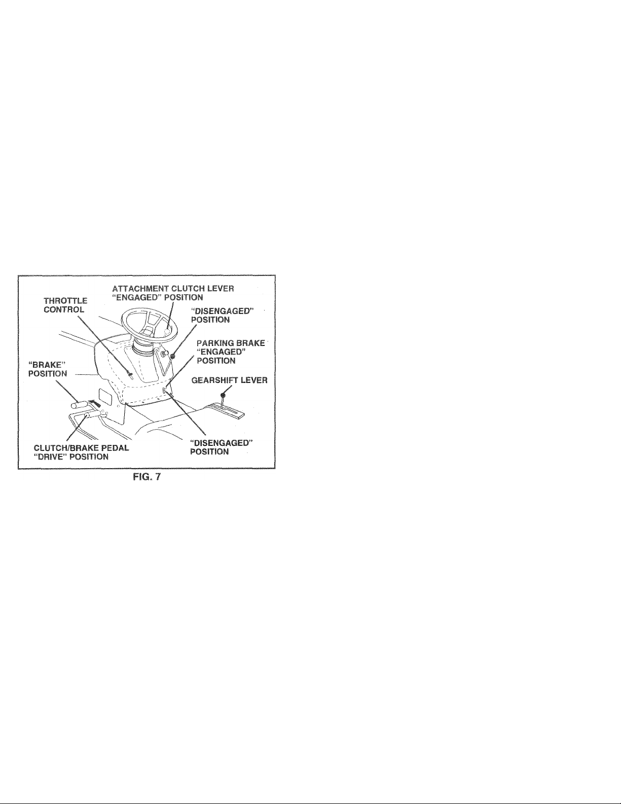
ATTACHMENT CLUTCH LEVER: Used to engage the
mower blades, or other attachments mounted to your
tractor.
LIGHT SWITCH: Turns the headlights on and off.
THROTTLeCriOhE control ^ Used for starting and
controlling engine speed
CLUTCH/BRAKE PEDAL: Used for declutching and
braking the tractor and starting the engine.
PARKING BRAKE: Locks dutch/brake pedal into the
brake position.
MOTION CONTROL LEVER: Selects the speed and
direction of tractor.
ATTACHMENT LIFT LEVER - Used to raise and lower the
mower deck or other attachments mounted to your tractor.
LIFT LEVER PLUNGER: Used to release attachment lift
lever when changing its position.
IGNITION SWITCH; Used for starting and stopping the
engine.
FREEWHEEL CONTROL - Disengages transmission for
pushing or slowly towing the tractor with the engine off.
10
Page 11
OPS ration
The operation of any tractor can result in foreign objects thrown into the eyes, which can
result in severe eye damage. Always wear safety glasses or eye shields while operating
your tractor or performing any adjustments or repairs. We recomme Me vision
safety mask over the spectacles or standard safety glasses.
aSti\CTOR
TO SET FT KKING BRAKE (See Fig. 7)
Yourtracior is equipped with an operator presence sensing
switch. When engine is running, any attempt by the
operator to leave the seat without first setting the parking
brake will shut off the engine.
® Depress clutch/brake pedal into full “BRAKE”, position
and hold.
• Place parking brake lever in “ENGAGED” position and
release pressure from clutch/brake pedal. Pedal should
remain in “BRAKE” position. Make sure parking brake
will hold tractor secure.
STOPPING (See Fig. 7)
MOWER BLADES -
• Move attachment clutch lever to “DISENGAGED” po
sition.
GROUND DRIVE -
• Depress clutch/brake pedal into full “BRAKE” position.
• Move motion control lever to neutral (N) position.
IMPORTANT: THE MOTION CONTROL LEVER DOES
NOT RETURN TO NEUTRAL (N) POSITION WHEN THE
CLUTCH/BRAKE PEDAL IS DEPRESSED.
ENGINE -
• Move throttle control to slow (*•) position.
NOTE: Failure to move throttle control to slow (««A)
position and allowing engine to idle before stopping may
cause engine to “backfire”.
• Turn ignition key to “OFF” position and remove key.
Always remove key when leaving tractor to prevent
unauthorized use.
• Never use choke to stop engine.
NOTE: Under certain conditions when tractor is standing
idle with the engine running, hot engine exhaust gases may
cause “browning” of grass. To eliminate this possibility,
always stop engine when stopping tractor on grass areas.
CAUTION: Always stop tractor com
plete ave, before leav
„
ing the operator's position; to empty
grass catcher, etc.
TO USE THR' QNTROL (See Fig. 7)
Always operate engine at full throttle.
• Operating engine at less than full throttle reduces the
battery charging rate.
• Full ffircftY- .offers the best bagging and mower perfor
mance
TO MOVE FORWARD AND BACKWARD (See Fig. 7)
The direction and speed of movement is controlled by the
motion control lever.
• Start tractor with motion control lever in neutral (N)
position.
• Release parking brake and clutch/brake pedal.
• Slowly move motion control lever to desired position.
TO ADJUST MOWER CUTTING HEIGHT (See Fig. 6)
The position of the attachment lift lever determines the
cutting height.
• Grasp lift lever.
• Fress plunger with thumb and move lever to desired
position.
The cutting height range is approximately 1 -1/2 to 4". The
heights are measured from the ground to the blade tip with
the engine not running. These heights are approximate
and may vary depending upon soil conditions, height of
grass and types of grass being mowed.
• The average lawn should be cut to approximately 2-1 /2
inches during the cool season and to over 3 inches
during hot months. For healthier and better looking
lawns, mow often and after moderate growth.
• For best cutting performance, grass over 6 inches in
height should be mowed twice. Make the first cut
relatively high; the second to desired height.
11
Page 12

iPERATIOf
tart mower blades b
)ntroL,
clutch control.
i *f*' b»»' i}-'f ri>
on mowers so equipped, or the dis-
harge juarb ir
ita
BL
itor io le
qinq att
lent dutch
RI
m
IE ENGINE
L (See Fig. 12)
»• i i '< i .Hoc
mer weight oil.
A level ground,
^ka
wipe clean, reinsert the
Hnh-
reme
li
hor C
03SÌ€
DnsngG engine oil, S9i
section in this manu«
insti
1>J W li until
• I avertili
f f! 'cof je O'i for
.'Of óH/,pT .iiihe
1 'ill mnuul)
VI i TK r r1t-SpOnSÌDÌ;Ì-
tCi i '•* TnrJ F ,1
I-|,ii ft'» 1 ' v'r i itA •!-?-di'engage
t'or f >r I, f‘ '■ n f; :5i/hee!ing
pork 'id- i! - I ( r, i ji i ¡T-I.itrs r-'crarawbar
of tractor.
® ','.1^ i 111 t.h ..•!,! ,t _t MOi-itioii With attach-
liiciT !|ii C Jilt ji
» Pull freewheel control knob out and hold in position by
inserting retainer spring into fonward hole of control
rod.
* Do not push or tow tractor at more than two (2) MPH.
• To reengage transmission, reverse above procedure.
NOTE: To protect hood from damage when transporting
your tractor on a truck or a trailer, be sure hood is closed
and secured to tractor. Use an appropriate means of tying
hood to tractor (rope, cord, etc.).
TO OPERATE ON HILLS
CAUTION; Do not drive yp or down
A
» Choose trie rrtowesi speed beic-'e startinq up or down
hills,
» A.vcid stopping oi chsngir'ig speed on hills.
• if CGwmg is necessaiy, move tnrottle control lever to
Slower position.
® If sfopping is .-ibsolutely necessary, push clutch/brake
pedal quickly to brake position and engage parking
brake.
• Move rnotion control lever to neutral (N) position.
IMPORTANT: THE MOTION CONTROL LEVER DOES
NOT RETURN TO NEUTRAL (N) POSITION WHEN THE
CLUTCH-'BPAKE PEDAL IS DEPRESSED.
• To restart movement, slowly release parking brake and
dutch/brake pedal.
® Slowly move motion control lever to slowest setting.
• Make all turns slowly.
hills with slopes greater than 15' and
do not drive across any slope.
AH
FIG. 9
12
Page 13

operation
ADD GASOLINE
® Fill fuel tank. Use fresh,
gasofine with a minimum of ^
QBSolinG will incressB CHibC
and reduce valve iife). Do
Purchase fuel in quantifies i
)T mix 0!i
it can be
days to assure fuel freshne
IMF FPU r tlbi*
BEI ' L „ I ¡ ■
- UL I V 1 I'l (
^T/r^ni-ir
1 ^ ^ ' W “ w t L /s oF mL d [
F'F Ì1 L'"ANi/Wfir£HGP-,DE
' ‘1^1 .'/T' . C'i t
WARHINC UquM.. ~ U hisiirlrd
■‘■jeh., ( a'U i t • uu* g <^.t ai '• o. pie'.'r‘fioli ran
strm't 'u I ' ,i|- I?;, nUiinationof
di-'dC -*UrO'. -t^r It VCldl' jO. <- 1 Qcli'Ugf- ihf it'J
syG'.'-n <f .r r.g.ft p rrci: ri-Uvay^ Tc ^/C'd e'~g‘'O
prub*'n.‘ 11.' iiw-f /Uu I t.uui U'^e emprieO b°tore ;io« •
age U _c u,/_ w ’ongas Diain f.ie gas tank seri the
er.gn,- an'i Ut >i un 'Ji.kl tha fue! ines and carburetor are
empty Udfc hi-¿h fuel nryi season Fee Storage Instfuctions for additional information. Never use engine or
carburetor cleaner producís in the fuel tank or permanent
damage may occur.
CAUTION: Fill to bottom of gas tank
filler neck. Do not overfill. Wipe off any
spilled oil or fuel. Do not store, spill or
A
use gasoline near an open flame.
TO START ENGINE (See Fig. 7)
When starting the engine for the first time or if the engine
has run out of fuel, it will take extra cranking time to move
fuel from the tank to the engine.
• Be sure freewheel control is in the transmission en
gaged position.
• Sit on seat in operating position, depress dutch/brake
pedal and set parking brake.
• Place motion control lever in neutral (N) position.
• Move attachment dutch to “DISENGAGED” position.
• Move throttle control to choke (|\() position.
Note; Before starting, read the warm and cold starting
procedures below.
• Insert key into ignition and turn key clockwise to “START’
position and release key as soon as engine starts. Do
not run starter continuously for more than fifteen sec
onds per minute. If the engine does not start after
several attempts, move throttle control to fast (%)
position, wait afew minutes and try again. If engine still
does not start, move the throttle control back to the
choke (i\l) position and retry.
jlsr unl©3cl©cl
Lise of leaded
)xide deposits
with gasoline.
K ■' V"' r. !•
-' h
.V. ' ' f ) U U t.U I ( f
* When engine starts, move the throt
Ì tn0 Issi
(•#) position.
• The attachments and ground drive
the engine does not accept the loac
' ft to warm up fc
)fi
:th€
using i
•sen
V ULu Vi'r ' - I ‘UifIJU m ‘ . .1 1 '
‘V'fici I il Jif - i ,ii .11 X I ,!1<- t 'll I ' .
ft '
> I O,
G.run*! n !'• - *'h. t >1« I) flurr, .*4¡ til- mill, n '
I ji I I >!,-■ i V - ■htrtile .uruUi ,'j L I
rhi_ >1 ^ , t»g>r- <H’>p t'■-II' " ’-I’l
50 - . '■ ( LO't K iP-r-1 O' tí I If - ’ -j I r II ill
temperature.
If i ,/v pfi »
• E'ct^ite in ii'M
111
'- 111
it
1'' I f Ip wt If. I ii 11 .n I nr
Í '('ri bfouL. b* v.a‘iTk-a up fcinw;
* Be :jib me tractor is on level orm-i-d
* Place th.. fTsotion coritioi levct in ney:r,,l
Release the parking brake and let the dutch/brake
slowly return to operating position.
* Allow one minute for transmission to warm up.
This can be done during the engine warm up
period,
• The attachments can also be used during the engine
warm-up period afterthe transmission has been warmed
up.
NOTE: If at a high altitude (above 3000 feet) or in cold
temperatures (below 32 F) the carburetor fuel mixture may
need to be adjusted for best engine performance. See “TO
ADJUST CARBURETOR” in the Service and Adjustments
section of this manual.
13
Page 14
PURG
iNSMISSIO^
IJTlOf^: Newer
ingage or di!
tile the sfioiti srun
A
d that the transmis
tractor for
trapped ai
I Of-( I .
{, M< • *-' f ' h . f ' / r L i/!l , I i
Hd'i i > M - r. , f L" T 'Ll If M
t EF' r.AJ . I rfl- rr ,v K.-r
“• f I ;< > M' rr , ipl |, I I- I iinccc i-lfil ' Ox,I I- ifl.'lid
f ,l • «0 0 ' t '
•> L'l'! hgagt, Uc•i-:r..:c!cr oy gbtii.a ffteAheci c 'ntml
in rit. whtPÍTig Djiioori TO Tl-^fJ~F*Cib f” in
thi.'. of iTidiiual)
• Sitting in the tractor seat, start engine. Atterthe engine
With motion control lever in neutral (N) position, slowly
disengage clutch/brake pedal.
• Move motion control lever to full forward position and
hold for five (5) seconds. Move lever to full reverse
position and hold for five (5) seconds. Repeat this
procedure three (3) times.
NOTE: During this procedure there will be no movement of
drive wheels. The air is being removed from hydraulic drive
system.
• Move motion control ieverto neutral (N) position. Shut
off engine and set parking brake.
• Engage transmission by placing freewheel control in
driving position (See “TO TRANSPORT” in this section
of manual).
• Sitting in the tractor seat, start engine. Afterthe engine
is running, move throttle control to half (1/2) speed.
With motion control lever in neutral (N) position, slowly
disengage clutch/brake pedal.
® Slew'/ rrcvt, rnoi'on {onh(-l bver io'watd, after the
liaJti m- ve* ap|.rox!ii aTi / fi't (5) *cet, ¿lowly move
mc'icf. c-mt'f.! ir ei m n-.- r c povticn. After the
írdí r.i fTicvf appKximat'iv ti''*-- (5i ffft return the
moiic iiccntrui level ic tne i s-uttal (,N) os don. Repeat
this procedure with th^ control lever three (3)
times.
® Your tractor is now purged and now ready for normal
operation.
0 > r prr '-f ‘ ,r ’raciot
is running, move throttle control to slow (<^) position.
tim
I •! Jf '--ii'li t U'*t r*l l1 <
■ ■ ;h mav have
- . u
-ff %p!-li.'-ipp 1 t it ‘fr f,,i f-t.ir,
} IS
1 for best
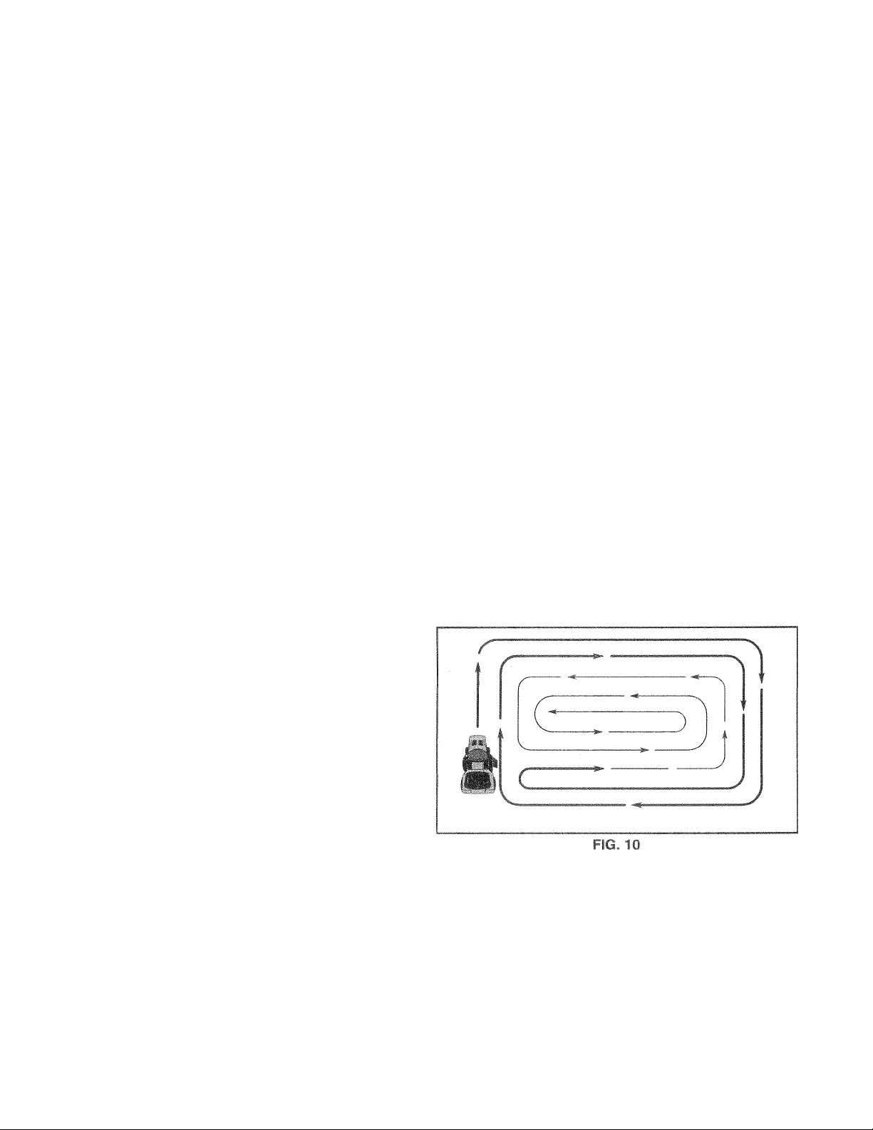
MFpj HOU
3f thi:
ft he jld b d to tnm-
mir
o d V ' i,| I ,n s >, ill « pemro me the-area
dWi itaC tw-ii.Dr f aitar'-jv ihf righto! if.fc
I r. 'f. i i<- ill i _ i‘.j> -Jo iboiion f
'I'or I'j '"c '• V min.ioit . .■iti-nQ
V.’r^r. rr< i irig 1' .V li'--'- "i I'l r p V! ning to tight
.. lUnt (iipp.rg 'iiil ijicof’v'ge iway from shrubs,
i'( > 'irivtw..V' h*i Atte! "•rir- Cl Twe rounds mmv
I! ih. ¡pp., dif. ‘"Ill mchno Icfi hano tu no until
fi<ii-(vd F'p, Id)
IT d! i. is A4'ctni-ly tall II shoiilc be mowed twice to
reduce ¡Add uiiJ pc mibifc fire hazard from dried clip
pings Make firci cut reldiiveiw high: the second to the
de^”iied heiaft
Do not rriow gra'*- when it is wet A/et grass will plug
rn&’ver and loom unde^iratte clumps Allow grass to
drv before tn..wir>g
AivVayS operate engr.c d* full ihroTle when mov/ing to
d'^sure betier mowing peiformance and proper dis(ha’'qo of TirtHial. Regulate ground speed by selectinc 3 low p-noug'' gear to give t^e mower cutting
p-rfer'” :n'fr a>- welfas the qualitv of cut desired
When operating attachments, select a ground speed
that will suit the terrain and give best performance of
the attachment being used.
lowing
IS!NG”in
manual.
14
Page 15

^’Wf/*^fOEni «H i ^c p><
* FILL IN DATES
AS YOU COMPLETE
!
FfilJI AR SFRVICF
I
—
> ^ L hi I 'H
Check Tire Pressure
ill- ‘ r I, ' - i-e rri
p
p
-I-- '-r-i-s't ■ I-1' .
Lubrication Chart
lie i-^i I -I F -'Me
. feC'l F.'l ' V! r • I'
y
B
Ch-_k 1 j'l 1 ' jlin'j
—
VT<-r
ik'
r
-
----
—
1
—
---------
'Ik-
,
1
V^7
....
y 1
.....
______
> 1
^ j
I.....
iS
j
✓ 1
1 J
diu.tp. 1-H hf') 7an='!iri
Ai |L=( Ma cri Crive Peit(3> Tensif f>
'-Lc k ErtJic- 1!' /0
Change Engine Oil
Clean Air Filter
C.
Clean Air Screen
N
inspect Muffier/Spark Arrester
G
✓
I Replace Oil Filter (If equipped)
N
Clean Engine Cooling Fins
t
Replace Spark Plug
Replace Air Filter Paper Cartridge
Replace Fuel Filter
1 - Change more often when operating under a heavy load or in high ambient temperatures. 5 - If equipped with adjustable system.
2 - Service more often when operating in dirty or dusty conditions.
3 - If equipped with oil filter, change oil every 50 hours.
4 - Replace blades more often when mowing in sandy soil.
✓
✓
^2,3
✓
^2
✓ 2
✓
^,2
✓ 2
✓
✓
✓ 2
✓
6 - Not required if equipped with maintenance-free battery.
7 - Tighten front axle pivot bolt to 35 ft.-lbs. maximum.
Do not overtighten.
if-RvICt-
——
1
p
ZI
___
p_——-
______
,
1 1
r 11
......
n
__ J
1 1
H
1
1
1
I
GENERAL RECOMMENDATIONS
The warranty on this tractor does not cover items that have
been subjected to operator abuse or negligence. To
receive full value from the warranty, operator must maintain
tractor as instructed in this manual.
Some adjustments will need to be made periodically to
properly maintain your tractor.
All adjustments in the Service and Adjustments section of
this manual should be checked at least once each season.
• Once a year you should replace the spark plug, clean
or replace air filter, and check blades and belts for
wear. A new spark plug and clean air filter assure
proper air-fuel mixture and help your engine run better
and last longer.
BEFORE EACH USE
• Check engine oil level.
» Check brake operation.
® Check tire pressure.
• Check for loose fasteners.
LUBRICATION CHART
@ SPINDLE ZERK
@ FRONT WHEEL'
BEARING ZERK
©ATTACHMENT-
CLUTCH
PIVOT(S)
® SAE 30 OR 10W30 Mu I OR OIL
©GENERAL PURPOSE CREASE
©REFER TO CUSTOMER RESPONSIBILITIES “ENGINE” SECTION
IMPORTANT; DO NOT Oil OR GREASE THE PIVOT POINTS
WHICH HAVE SPECIAL NYLON BEARINGS, VISCOUS LUBRI
CANTS WILL ATTRACT DUST AND DIRT THAT WILL SHORTEN
THE LIFE OF THE SELF-LUBRICATING BEARINGS. IF YOU
FEEL THEY MUST BE LUBRICATED, USE ONLY A DRY, POW
DERED GRAPHITE TYPE LUBRICANT SPARINGLY.
SPINDLE ZERK@
FRONT WHEEL®
■ BEARING ZERK
15
ENGINE®
Page 16
TRACTC
Always obsí5R3rve safety rules when performing a
nv rr
BRAKECJPERATION
It tractor rec
at high spee
(See “TO A
ments sectilon of this manual).
juires more than six (6) feet stoppir
j 1 •!(I'ji 1 -.1 4« ii i i 11 1 ‘1 i ,.i ) ' b
iDJUST BRAKE” in the Service a
ance
TIRES
> S/'.n ii I p’i’i 1-r II fr u' ' r _il t:r - (''-t ‘PP 'L‘-
UCT SPECIFICATIONS” on page 3 of this manual).
» i*«'fi II ‘ <q '^lií! '<i' a in£t f"! •'mtrtj chrmi-
Cdl' Í ( I ‘li'hi fillT -
• fii-jih <'r'<T !• P'h-, !>-e; ruts -h^io ooi-rts and
■dri* I h-/srr|' ihjT n >v ' 5‘i;'F [,r- daf'iape
NOTE, T i sea! tire punctures and prevent flat tires due to
slow is-sks. Tire sealant 'Way oe purchased from your local
parts rieaiei Tire se-aiant also prevents tire dry rot and
corrosion
)SHARPEN
,re should be f
balanced blade
The blade car1 be she!
wheel. Do no
To check blacle balan.
steel bolt, pin,
li ( '• 1 f( Ч
ar A.
>• ‘ 1 ! j .'f .,11' -3, uil'Cr.</1 the steel bolt
t,' (.1,1I. .If t ill I |j|! pSi-ilv I viltti the gruind.
if ! I d( I h.l • d I? h'luid lomain in e hfiisontal
. u, 'iuii I.. " I end 'j fht t latJe mo/es downward,
n -rp.-r, F." t,i M I iTtii th<- blade I- bcthriitd
IJCJIF iJf.ii.d'W- iviinji bjileoi my blade ihtloDesof
ihe . e.ite hul' tf bv centered but are not.
1 BLAC
! vvill CSÜ'
! attemp
or a cor
ow the
CENTER HOLE
12)
'3-
le blade balanced. An
iSive vibration and even-
u engii
•pened
iiith a file or on a grinding
narpen while on the mower.
v ou Will Hoed 0 5/8 diameter
ancer. (When using a cone
i isu Ljctions supplied with bal-
/
\
BLADE CARE
For test msults mcwer blades must be kept sharp. Re
place bent or damaged blades.
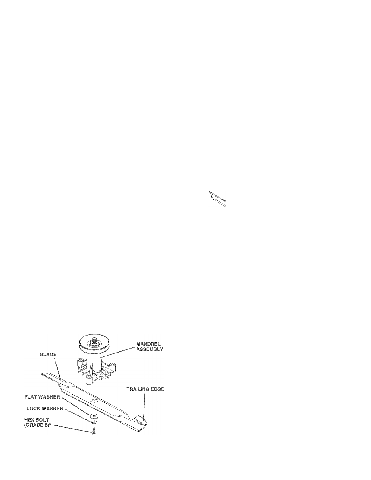
BLADE REMOVAL (See Fig. 11)
• Raise mower to highest position to allow access to
^ blades,
• Remove hex bolt, lock washer and flat washer securing
blade.
® Install new or re harpti i. d blade with trailing edge up
towards der I* a- -hown
• Reassemble hex belt lock we->her and flat washer in
exact order a- ,-howii
• Tighten boft sef urel/ (30 35 Ft, Lbs. torque).
IMPORTANT: HI Aü¡- B"'L T IS GRADE 8 HEAT TREATED.
NOTE: Wedonc-i -mmend sharpening blade - but if you
do, be sure the biant, is baianceu
*A GRADE 8 HEAT TREATED BOLT CAN BE
IDENTIFIED BY SIX LINES ON THE BOLT HEAD.
~ ^ RGm
\
5/8" BOLT
OR PIN
FIG. 12
BLADE
BATTERY
Your tractor has a battery charging system which is suffi
cient for normal use. However, periodic charging of the
battery with an automotive charger will extend its life.
• Keep battery and terminals clean.
• Keep battery bolts tight.
• Keep small vent holes open.
• Recharge at 6-10 amperes for 1 hour.
TO CLEAN BATTERY AND TERMINALS
Corrosion and dirt on the battery and terminals can cause
the battery to “leak” power.
• Open battery box door.
• Disconnect BLACK battery cable first then RED bat
tery cable and remove battery from tractor.
• Rinse the battery with plain water and dry.
• Clean terminals and battery cable ends with wire brush
until bright.
• Coat terminals with grease or petroleum jelly.
• Reinstall battery (See “CONNECT BATTERY” in the
Assembly section of this manual).
16
Page 17

RESPONSiBiLiTies
V-BELTS
Check V-belts for deterioration and wear after 100 hours of
operation and replace if necessary. The belts are not
adjustable. Replace belts if they bOQin to slip from wear.
TRANSAXLE COOLING
mo 'fi i „ .‘H .j ft ..i‘i ji ' i> 'iiO rkept
cle It u, - '.n ¡. iu ^ > niin-j
Dr I'ul r*ne c f I*" '1 -ri .t r< I .sionwhi’e spqine IS
rurininq Oi vvli le tf - iirr.^ntc-ioii C' het
• in-fjt- li'noDi I i- f.'-Vi. pf'«je.s jfeirfe^iand
clean.
® lr.£p=ci lOC'iifo liv fo liti ■ j'S'i-ri.ppings and Other
fiì-ir T" j. . ,1 tViriopt le itròls do not use
'-.rip, fj ai" " hijh \ rrr iir' opnyer tr rlf'jn
cooling fins.
TRANSAXLE PUMP FLUID
The transaxle was sealed at the factory and fluid rhaintenance is not required forthe life of the transaxle. Should the
transaxle ever leak or require servicing, contact your near
est authorized service center/department.
ENGINE
TO CHAN
Determine temp«
All oil must meet
# p
sure tractor is on level surface.
Oil will drain more freely when warm.
Catch oil in a suitabte container.
H„nr.’ I C I till -P tvi £T' ‘ 3 't' I ti >1 f , Jlo ‘■ rirs
ti Ciitor Itic mcir-' cfie tli"r mijui!
RfetTiove hr j r ' luc
AtifruJI Itari— a.iplrt.rly. iliin. • plug
and tighten securely.
Ht,ill»-rc V with s'th.fl'yti • 'I -idi|Sf' " ' ‘ ' <r
slomly L ) '„I 0v6dii F nr 3p| r nimyi- <" if r'
‘PROD AT -c:FCiF'-“AV' fV th . » ir.>
manual.
Use gauge on oii fill cap/dipstick for checking level. Be
sure dipstick cap is tightened securely for accurate
reading. Keep oil at “FULL” line on dipstick.
NGINE OIL (f
»erature ranae
LUBRiCATION
Only use high quality detergent oil rated with API service
classification SF, SG or SH. Select the oil’s SAE viscosity
grade according to your expected operating temperature.
SAE ViSCOSITY GRADES
0° 30° 32° 40° 80“ 100“
»C -30” 20° -10° 0° 10° 20° 30° 40°
TEMPERATURE RÄNGE ANTICIPATED BEFORE NEXT OIL CHANGE
NOTE: Although multi-viscosity oils (5W30, 10W30 etc.)
improve starting in cold weather, these multi-viscosity oils
will result in increased oil consumption when used above
32°F. Check your engine oil level more frequently to avoid
possible engine damage from running low on oil.
Change the oil after the first two hours of operation and
every 50 hours thereafter or at least once a year if the
tractor is not used for 50 hours in one year.
Check the crankcase oil level before starting the engine
and after each eight (8) hours of operation. Tighten oil fill
cap/dipstick securely each time you check the oil level.
'"eo“-20°
17
Page 18

r I r* iCif K, , '- ¡'I. V
AIR FILTER (See Fig. 14A)
Your engine will not run properly using a dirty air filter.
Clean the foam pre-cleaner after every 25 hours of opera
tion or every season. Service paper cartridge every 100
hours of operation or every season, whichever occurs first.
Service air cleaner more often under dusty conditions.
• Remove knob(s) and cover.
TO: LF .-I t “'HL-.O ! / M' h
• Slide foam pre-cleaner off cartridge.
® Vv'rti ii i.i inoiid Orr iQf-n! si. p'f.i' I.
/ly'(-. > H Ji" 'll - ' Ojh c 111
‘ . a;ui /1 T i>i > nu" L il .'V 4 !■ <n , i :i, -ih ,0 beiif
< luih rd - f' ■ * tit. ( ii
^ P "t Jliy U On *1- ISpL-Li- t“"Ci-c-FI.
® HeinOai! iirt-^l'-ona o/c-r cattiidyr
• ric.Fisr.gi 1..0/0 and cm urc with knob(^).
TO SERVICE CARTRIDGE
• Remove cartridge nut.
• Carefully remove cartridge to prevent debris from en
tering carburetor. Clean base carefully to prevent
debris from entering carburetor.
• Clean cartridge by tapping gently on flat surface. If very
dirty or damaged, replace cartridge.
• Reinstall cartridge, nut, precleaner, cover and secure
with knob(s).
IMPORTANT: PETROLEUM SOLVENTS, SUCH AS
KEROSENE, ARE NOT TO BE USED TO CLEAN THE
CARTRIDGE. THEY MAY CAUSE DETERIORATION OF
THE CARTRIDGE. DO NOT OIL CARTRIDGE. DO NOT
ENGINE OIL FILTER (See Fig. 14B)
Replace the engine oil filter every season or every other oil
‘ ‘ I t I ' ■ ‘ I . . , ( f I , ( WJ
} counterclockwise. Use a
ibl
!;S
»ii I ■ 'libber pdol-etApply a thin coating of r
on replacement oil filtei
In rtrif ^Fr-.ti 1.1 Til -• ‘ ; n.iiiii g do( kwise until
r.jbl V'or-C I " iii i ; (ii-tivj ".ii'-Gre then tighten
filter an additional 1/2 to 3/4 turn.
i ill i! - r>i i • 'I ,—V. 1.1 lO (-RANGE EN1 i«i[ JIL .1, ir . .1., • rt. .i.jiiLwi) Forapprovimar- (ir.i t, , i'H 1.1. i SPECIF If. ATIONS’ on
f) O' i i f d, I i
iw'' . h ‘ I. r . Cjtrecionvleaks
bt futt p!r U t<j(r I I'.T • t'j'l "OOMlnri
OIL FILTER
FIG. 14B
ENGINE COOLING FINS (See Fig. 15)
Remove any dust, dirt or oil from engine cooling fins to
prevent engine dan.age from overheating.
• Remove sroews fiom bcwet housing and lift housing
and dipstick tube assembly off engine.
• Cover oil fill opening to prevent entry of dirt.
• Use compresseo air or stiff bristle brush to thoroughly
clean engine cooling tins
• To reassemble, reverse above procedure.
FIG. 14A
CLEAN AIR SCREEN (See Fig. 14A)
Air screen must be kept tree of dirt and chaff to prevent
engine damage from overheating. Clean with a wire brush
or compressed air to remove dirt and stubborn dried gum
fibers.
18
Page 19

CUSTOMER RESPONSIBILiTIES
MUFFLER
Inspect and replace corroded muffler and spark arrester (if
. >t'i i|f* ' ate . tire ha li mi1;»1 Jiimo'
f “pL - |j i i.)U f't'- l"cyii'"rg ut'^^-'1 >~i'. oing
I f r-t. i- K,l h" „ s, pernt>'/i
yruur- iimt '^pdrk D.uq type dii«f gap seiting ai6 sho*ii ii i
f-RCC'Uh ! tsPEh'FlOfJa on i)dqe2 >ii if(K fnaiiuril
IN-LINE FUEL FILTER (See Fig. 16)
The fuel filter should be replaced once each season. If fuel
filter becomes clogged, obstructing fuel flow to carburetor,
replacement is required.
• With engine cool, remove filter and plug fuel line
sections.
• Place new fuel filter in position in fuel line with arrow
pointing towards carburetor.
• Be sure there are no fuel line leaks and clamps are
properly positioned.
• Immediately wipe up any spilled gasoline.
FIG. 16
CLEANING
• Clean engine, battery, seat, finish, etc. of all foreign
matter.
• Keep finished surfaces and wheels free of all gasoline,
oil, etc.
• Protect painted surfaces with automotive type wax.
We do not recommend using a garden hose to clean your
tractor unless the electrical system, muffler, air filter and
carburetor are covered to keep water out. Water in engine
can result in a shortened engine life.
19
Page 20

CAUTION: BEFORE PERFORMIMG ANY SERYiCE OR ADJUSTMENTS:
• Depress clutch/brate pedai fylif Sis'm sm. parking brake.
• Place motion control lever in neutral (N) position.
A
• Place attachment clutch in “DISENC3AC3ED” position.
• Turn ignition key “OFF” and remove key.
® Make sure the blades and all moving parts have completely stopped.
• Disconnect spark plug wire from spark plug and place wire where it cannot come in contact
with plug.
TRM -CiP
*^0 hEPGVr I (Om Piif. 1TI
MCWi v'dili ) - i I. .i-fi nil'. r..”ilector.
ittactimc ilute
“DiSENG. L‘ u _iiion.
^ Ml c t4idcl-.n< i.tict I' .^,ilMVv''mu lowei ('lowerto its
• Roll belt off engine pulley.
• Disconnect clutch rod from clutch lever by removing
retainer spring.
• Disconnect anti-sway bar from chassis bracket by
removing retainer spring.
® Disconnect suspension arms from rear deck brackets
by removing retainer springs.
• Disconnect front links from deck by removing retainer
springs.
• Raise lift lever to raise suspension arms. Slide mower
' out from under tractor.
IMPORTANT: IF AN ATTACHMENT OTHER THAN THE
MOWER IS TO BE MOUNTED TO THE TRACTOR, THE
R.H. AND L.H. SUSPENSION ARMS MUST BE REMOVED
FROM TRACTOR.
TO INSTALL MOWER (See Fig. 17)
• Raise attachment lift lever to its highest position.
• Slide mower undertractorwith discharge guard to right
side of tractor.
• Lower lift lever to its lowest position.
• Install mower in reverse order of removal instructions.
CLUTCH ROD
SUSPENSION
ARMS ^
RETAINER
SPRING
ANTI-SWAY BAR
CLUTCH LEVER
RETAINER
SPRING
ENGINE
PULLEY
RETAINER
SPRINGS
(BOTH SIDES)
RETAINER
SPRINGS
(BOTH SIDES)
FIG. 17
20
Page 21

SERVICE AND AD.IiiSTi»4EfS'r-^
Adjust tli6 mowsr whif0 trsctor is psrkscf on l©¥s! QrouncJ or
toi,r*ivr ' di"" r ' ' I u I I ^f-
"PRODUCT SPECIFICATIONS” on page 2 of this manual).
If tires are over or underinflated, you will not properly adjust
yuui 11 luvvei.
Sir- ‘ i'T -[Ml ' ^ -id 19)
• P'-ji se mow L-. li- h.u htst t- j-ition
• At the nidpu nl uJ -oth side.- o- mower measure height
from bottom edge of mo /srto ground Distance “A” on
uurti side-. "I
fj each _thcr
• IT ad uotnent i- no- or, rn-te :djii*^iRtrnt on one
side
of
rruwe.
• To raise one side of mower, tighten lift link adjustment
nut on that side.
• To lower one side of mower, loosen lift link adjustment
nut on that side.
NOTE: Three full turns of adjustment nut will change
mower height about 1/8".
•' Recheck measurements after adjusting.
ifiowt.
only
:ujid
be
ihe c.ame tr within 1/4"
IT i
IMPORTANT: I
THE FOLLOWl
NECESSARY, E
EQUALLY
U IRP TO .
iTH F
) MC ¡VVER WILL STA' Y LEVEL
SIDE
SIDE.
To obtain
should bee
|)0 lit! ■!
Checl" ooju i/t'e a ih I 'U - ‘i‘.
tapceii fly .. s r 1
best cutting results, t he rfiowe r hoL
steels,o that the front is approximat
1 the
rear when the mo wer is in f is hia
eiy 1/
iure dist bottom
edge n ^ - ■ r h.i m' .g ;■ r
• Before making any necessary adji
botl 1 ti If! i' JU y' . I - i ‘.
lents, check that
h links should be
cippiC V‘t ia'( I' f (H
» It link ■ -<Y ii a -r i'Mf ill,. ^ ,1! 11 r!<-ill.i-i ; r^'
lenuth .»hi ti'f''
» To inwei f.oiit t)‘ .I'lwu li>j'l I't.i “E" cu both irurl
links a' -quel i»oTiber cf lurtis
• When Oiatarice D la ' A »o b_" L'Wer ui fiont thcii
real, tighten nuts F ag-nnm trjr.r i,-»n on both from
links.
• To raise front of mower, loosen nut “F” from trunnion on
both front links. Tighten nut “E” on both front links an
equal number of turns.
• When distance “D” is 1/8" to 1/2“ lower at front than
rear, tighten nut “F” against trunnion on both front links.
• Recheck side-to-side adjustment.
SUSPENSION ARM
FIG. 19
LIFT LINK
ADJUSTMENT NUT
21
FIG. 21
Page 22

REPLACE MOWER BLADE DRI¥E BELT
(See Fig. 22)
The mower blade drive belt may be replaced without tools.
Park the tractor on level surface. Engage parking brake,
BELT REMOVAL -
• Memove mower irom iractor (aee "ou htiviuvE
ifV'.iM' ’■ >f' i' H, !'‘< ( I .-iiid 0l> I f' dl.-y .
• Puii bei! away from mo¥#er,
bELi IM-TV I TP N
'f, L1 I ' V' I f It II or ' I I. ’ Cl , jl
VrT - . t-r'i i ,ri-<0. jH., .• ' iiOiu-rill belt
guides.
' ir t„<i .,]f (,/< >1 . ^-1 ‘ r '.t rof-v
Road test iractorfor proper stopping distance as stated
above. Readjust if necessary. If stopping distance is
still greater than six (6) feet in highest gear, further
mainteriance is necessary. Contact your nearest au
thorized service center/department.
I •, < T t I L
Iv-e«* ^ fi. ‘-Aj
f rii h- ii r'f.i .
II W .rtofii'f- ilFr' ■
, O' HELT
R wl !!• ” f , ngage parking brake.
ition guide decal on
NA < tn ■id- - .f ipfr r: ft =
Remove mower
section of this n
inual.)
VE MOWER" in this
• hi 'i I . [ 0 f II I F. ij ‘
• Rtnit >• Чч .И11 > ii'cv ■ hr and clutching idler.
» Hi|!| bf ii bC f- L vva (i IP-. oi if-Uor. Carefully remove
1 e!t uf WrVub fmrii i чп vni'.'-ifin input pulley and over
ГО ,l!tq fan
• Full belt toward ft '1 ч tf traf tci- and remove downward
from aro' nd encinp pulley
• Ih'.tall пел bc-l! t / ifcvrrbing above procedure.
IMPOnrANT MAkF SURE UPPER BELT KEEPER IS
POSiriONEf. PRr.ppfl. / BFTWEEri LOCATOR TABS.
TO ADJUST BRAKE (See Fig. 23)
Your Ldctor I r luipoed ^ sd(> st'Die brake system
which !■ - rroi'ntteJ <“'n s'd- f. the tra'sa'Ic.
Iftrarif' '■^gu-'ei: ¡0're that -i/iLi feet =t(pping distance
athighrf.fci-u iL i ,= ibicke‘nustbeadjusted.
• DeprF-':f lijt''hTbr.'sFepP09i ind-'nfj^gp perking brake.
• MeasLtt distance between b"ikn cperaiing arm and
nut on brake rod
• If di'ienct IS othe tnan i 'O' L-ormn jam nut and turn
nut’ u.vii c. b-eomf t c/gg Retighten jam
nUl dO'TlIWt t ‘t
22
Page 23

SERVICE AND ADJUSTMEN'f
ro ADJUi
Fig, 25)
The motion control
adjustment should
If for any reason tf
position while at as
friction pack locate
« y j \ Ticii tOI >
ignition Key to
Li aKc.
• Adjust motion control lever by tightening adjustment
locknut one half (1/2) turn.
NOTE: If for any reason the effort to move the motion
control lever becomes too excessive, reverse the above
adjustment procedure by loosening locknut 1/4 to 1/2 turn.
Road test tractor after adjustment and repeat procedure if
necessary.
Miijif.ri aiiThui iStt
lever has been preset at the factory and
not be necessary.
10 .motion control lever will r lot hold its
elected speed, it may be adju i ,
' r h- ’ '1 , O'- '1 ti". ission.
1- ' i>r.' -0 rrp tr-cir>r
r r 1 i dii S'"" - pf rf-incj
turn ng
TRANSMISSION REMOVAUREPLACEMENT
Should your transmission require removal for service or
replacement, it should be purged after reinstallation and
before operating the tractor. See “PURGE TRANSMIS*
SION” in the Operation section of this manual.
"O REteo^^t MH ft i s i K itt f
(See Fig. 26)
« R innï t f in Ovis tf
* DIUL>t\ up ciAlt? tsfeiOui
* Fismov© 3x1© cov©r,
Af'-'inU 1 1
not lose).
• t iji |IK
a 'j,> 1 1 1 t-c-»., ,1
anc Cxi- 1 r f 1 qi
NOTE: To seal tire punctures and prevent flat tires due to
slow leaks, tire sealant may be purchased from your local
parts dealer. Tire sealant also prevents tire dry rot and
corrosion.
WASHERS
RETAINING
RING
- 1
H r -
eiv.
retaining ring
■ wheel conta
»semble.
r. align groo:
in rt
writ
TO ADJUST STEERING WHEEL ALIGNMENT
If steering wheel crossbars are not horizontal (left to right)
when wheels are positioned straightforward, remove steer
ing wheel and reassemble per instructions in the Assembly
section of this manual.
FRONT WHEEL TOE-IN/CAMBER
The front wheel toe-in and camber are not adjustable on
your tractor. If damage has occurred to affect the front
wheel toe-in or camber, contact your nearest authorized
service center/department.
AXLE COVER
SQUARE KEY
(REAR WHEEL ONLY)
FIG. 26
Page 24

r- ijjr. ilIMPPrJTS
whe
timail
WEAK BATTERY
iri€
srotectic
fr I If! be
ro START
A
If your battery is too weak to s' lari the snginei
ifl.tl-t' J- 'i k ’ lt( ' 1.1 Bra Lissd for
rr.sfiinj -v, if 1. < .r
IV!»-* -p fU'J 1 ■ H ' 1 !/ 1 '
VOLT NEGATIVE GROUNDE D SYSTEM. T
fl IS EQUIPPEC
•L eiHti
.'FHICI L ,il t ' G M A 12 VOLT i
.RvlUH . [ jTI
BATTERY TO STARTO
:R VEHICLE
II . 4'r 1 Pn ' f-lf
TO ATTACH JlJyPER C
* Connect each end o
Irli t'lidlos Ol I
..1 I f • the i-Ri.l iIjE“
jI i i<i . le not 10 shore
LI I n
* It-nnecicne -no i ih- * t r-LI-to the NEGA-
TI\/[ o, terriiK m <jt fuHi/ H ]f ! L' ti >/
® ('onneri tne >-ih I rf !i I Lo(i cable to good
( H'Si: IS ' 1 *r r ti,. . lU^J tiiik and battery.
TO REMOTE C«H1 t ‘ r->0 ^ V OHtTR ■■
* BL T c Ì .'nr • 1 'jiid to n from the fully
CrifTJ ribc:tt-
* RLn<abOi'i- II i.,| ,th b iVine:
Si ¿*:i yrAi-t\ ijui
Pul! bulb holdof 1
out of th.e hoi
iid@ of th6
oriiL .
1 uuiu III 1 IU8UGG at
back into the hot
0 In the !
iU pL
» ■■ T
Close hood.
INTEai CCKS AMP REl AYS
• z-LZ- zi y.-nia'>d ‘iiriro rrec uauEC vutr trocOr t.j run
p' r.rlv ' lor. •'onn-nq Of I r-o r-nf jt ffom starting
® { oFi I jvirin.j '~ffc FiHftrrai 'Ainna diagram in the
Fiepan Barts ci* zi on of ihi- menual ’
TO REPLACE FUSE
hepOc- witii A' at-ip autjniotiv'F lype plug-.n fuse The
fuse holder L lorair-d behind the dash
TO REMOVE HOOD AND GRILL ASSEMBLY
(See Fig. 28)
• Raise hood.
• Unsnap headlight wire connector.
• Stand in front of tractor. Grasp hood at sides, 1
engine and lift off of tractor.
» To replace, reverse above procedure.
PCSIIR'E "FPStiilf I.
'x
ULi-WJL TERMINAL
CHARGED
Page 25

9.; :Srs-
ENGIf
T*0 &
1 he fhrc
MUST THRC
ittle control has
adjusirntjnt should not be
describe
d below before
necessa ry, proceed as fi
• With engine not run
from
level
® ChOi
in gc
Ij f 1 ‘ ^ f
;k that holes “A”
ivernor plate line
- fO 1
loos^an clamp screw £
iligned. Tighter
are c
ITTLE CONTROL CABLE
been preset at the factory and
■ necessary. Check adjustment as
1 , 1 !,i I* 1 •' 1 .
Dliows:
1 ■( 1 t L-i JO- t" * 1 />-r
i.y
-
i| 1/ poyi
1 t 'it,' M
i< J',.. > 'hmh!'. ^-1 ir i!rir!l holt s
, ' ,, f :■ -w •
I ,
' Jf wly u " '
, , t
fi hid Ir I ; -,i ’ 1 (Is
j. I'd- ",c w rrl aliqrt'i,
. If .
h<
Final
Ifni
line
3K
holdl
I urn luie bpeeo surev
8 /Ur
11 1 ,
. ,1,
<|v . 'lii >
turn idle mixture valvi
gins to die and then tur
girie runs rough. Turr
bei
ri those two positions
throttle le
!
• Ft
i ', ti; h ^ r.- ',11 1 I r
poi
, il >11... > «'•I. r-.i' 1 m L'l
rorn slow
coiK'h'j' _ii,v i it *<■ c-_ m( ' .
cites b! HuOil ily.
tr
n idle
speatl
igirie c
iier-
High speed stop is factory adjusted. Do not adjust -
damage may result.
IMPORTANT: NEVER TAMPER WITH THE ENGINE
GOVERNOR, WHICH IS FACTORY SET FOR PROPER
ENGINE SPEED. OVERSPEEDING THE ENGINE ABOVE
THE FACTORY HIGH SPEED SETTING CAN BE
DANGEROUS. IF YOU THINK THE ENGINE-GOVERNED
HIGH SPEED NEEDS ADJUSTING. CONTACT YOUR
NEAREST AUTHORIZED SERVICE CENTER/
DEPARTMENT, WHICH HAS PROPER EQUIPMENT AND
EXPERIENCE TO MAKE ANY NECESSARY
ADJUSTMENTS.
TO ADJUST CARBURETOR (See Fig. 30j
The carburetor has been preset at the factory and adjust
ment should not be necessary. However, minor adjust
ment may be required to compensate fordifferences in fuel,
temperature, altitude or load. If the carburetor does need
adjustment, proceed as follows;
In general, turning idle mixture valve In (clockwise) de
creases the supply of fuel to the engine giving a leaner fuel/
air mixture. Turning the idle mixture valve out (counter
clockwise) increases the supply of fuel to the engine giving
a richer fuel/air mixture.
IMPORTANT: DAMAGE TO THE NEEDLE VALVE AND
THE SEAT IN CARBURETOR MAY RESULT IF SCREW IS
TURNED IN TOO TIGHT.
PRELIMINARY SETTING -
• Air cleaner assembly must be assembled to the carbu
retor when making carburetor adjustments.
• Be sure the throttle control cable is adjusted properly
(see above).
• With engine off turn idle mixture valve in (clockwise)
closing it finger tight and then turn out (counterclock
wise) 1 full turn.
25
Page 26

¡rnmediately
the season o
)ur trac
:ior will
■for
‘NOINE
CAUTION’ Never store the tractor with
gasoline in the tank inside a building
wr -'"'p if *f7-Ax / »' a'"h • V I*'*», *
'► -pii-rti ihiow the er»iJ«nr tu -a.
,Htrriii>s ifi -in»' em
!HAI rc^H
pA.jit , (|,r,s rr i jtr. i'j t It i'v! iiA when
«riiv.ii f'l i> ,tx I !• ■ px II.'J . t (irit>x (.Car. !i ¡nor
>iiL|li!. i-rru aÌ iJitf ijr iw [ ' tf«-. 'Z’jic ina
clean, dry area.
Cif^aiiAii r Vifidu'iC ' > ‘L/fJ||iC i.iii c C Link rner
ill ‘ |hx . C.|,i|t;0 Wii n . I òii_ iKdhJtjf}
« liiApect tnrl replce b'^lts n riecesser/ (oee belt ri -
placement in Tructiotw iti *ni oc. nee and AdiustmeiAts
section of this manual)
• Lutroste db "-hotfin ,n the Customer Responsibilities
iictiou (if (hit riii-iruai
• Be sure that all nuts, bolts and screws are securely
fastened. Inspect moving parts for damage, breakage
and wear. Replace if necessary.
• Touch up all rusted or chipped paint surfaces; sand
lightly before painting.
BATTERY
• Fully charge the battery for storage.
• After a period of time in storage, battery may require
recharging.
• To help prevent corrosion and power leakage during
long periods of storage, battery cables should be
disconnected and battery cleaned thoroughly (see “TO
CLEAN BATTERY AND TERMINALS”
tomer Responsibilities section of this manual).
• After cleaning, leave cables disconnected and place
cables where they cannot come in contact with battery
terminals.
• Be sure battery drain tube is securely attached.
• It battery is removed from tractor tor storage, do not
store battery directly on concrete or damp surfaces.
in the Cus
ilv1t
DEPOSITS
SYSTEM PA
FUEL HOSE
EXPERIENCE IN
FUELS (CALLED
I'V T r '-f.fii 1 „I
'-t F .‘Oil dD', I hrMdlCli OF AUDS DURING
< '/• M i"!C ' f TJ D' M' Gb fuel
>' r 11r ' 11 Ids’ vH ' I lij - '"orame
I :
-OB
■ • I ' ILi f . Mi Ml! r I TF>,
I* ( 1!, I .IJ'U», Ll.R^-r-b iloO
IT,
a 11 - |i-*r “lCOHuL BLENDEü
-H 'L ■ )- iMIfir -PHAilOi. OR
FRa.m i/Hr-TijHF A'l-nCh LEADS
lEVENl
S > I. ■ i , I limi 'UL'
51
iVi
» Drain the fuel tank.
' I t ii.‘_ tup' T, I Lj I ui uiif'l lie tuci lineo and
Ot III* ( r *rt Mil M
“ I ijx b . ,1 jr)ijiL*..r* leaner ptuducts mthe
)ij'. 'if |.uirii 4i» .it cMiTHge may occur
® IJ i.- h iutLi iH /f Ar MWiri
NOTE Fuel 'Mbili/ef .& an acceptable alternative in
rr.inirriiz.ing ttie fcrmatior 1 fuei aum deposits during stor
d'3f lij anbilMM to gasoline m fuel tank or storage
container A|wa,= tjiiew tic mir ratio found on stabilizer
container. Run engine at least 10 minutes after adding
stabilizer to allow the stabilizer to reach the carburetor. Do
not drain the gas tank and carburetor if using fuel stabilizer.
ENGINE OIL
Drain oii (with engine warm) and replace with clean engine
oil. (See “ENGINE” in the Customer Responsibilities
section of this manual).
CYLINDERS
• Remove spark plug(s).
» Pour one ounce of oil through spark plug hole(s) into
cylinder(s).
• Turn ignition key to “START” position for a few seconds
to distribute oil.
• Replace with new spark plug(s).
OTHER
• L I ■ t -(')> < osnlin T(... cn eason to another.
• r { h,- /r,m ( ^ uiiriF f ai. it sour can starts to rust.
Re i it>r or i>111 yv.ni qd'jcline will cause problems,
® h f I ■ibk t ,r^ /oi't l. r k f indoors and cover it to
yi I, pi. ic cix-n fmr ’ duM in 1 Jirt.
• ■ ( > * yruilM'iLi vilh A uitable protective cover that
d( .X not rt iihfiioiiur . Du n't use plastic. Plastic
tMiiutbn o' if whirlialk w^toiidensationtoformand
'\r*''r'U”- oi'M'jtt.'t t '•'jxt
IMPGFTLi'r neVED COVER TRACTOR WHILE ENGINE
AN VARM.
'26
Page 27

FSHOOTING POINTS
PROBLEM
Will not start
Hard to start
Engine will not turn over
LISE
1, Out of fuel.
Engine not “CHOKED” property. 2. See “TO START ENGINE” in Operation section.
2,
3. Engine flooded.
4, Bad spark plug.
Dirty air filter. 5. Clean/replace air filter.
5.
6. Dirty fuel filter. 6.
7. Water in fuel.
Loose or damaged wiring.
8.
Carburetor out of adjustment. 9.
9.
Engine valves out of adjustment. 10.
10.
1. Dirty air filter.
Bad spark plug.
2.
Weak or dead battery. 3.
3.
4. Dirty fuel filter.
5. Stale or dirty fuel.
6. Loose or damaged wiring.
7. Carburetor out of adjustment.
Engine valves out of adjustment.
8.
Clutch/brake pedal not depressed.
1,
2. Attachment clutch is engaged.
Weak or dead battery.
3.
Blown fuse.
4.
5. Corroded battery terminals.
Loose or damaged wiring.
6.
7. Faulty ignition switch.
8. Faulty solenoid or starter.
9. Faulty operator presence switch(es).
CORRECTION
1. Fill fuel tank.
3, Wait several minutes before attempting to start.
4,
Replace spark plug.
Replace fuel filter.
7.
Drain fuel tank and carburetor, refill tank with fresh
gasoline and replace fuel filter.
8. Check all wiring.
See To Adjust Carburetor” in Service Adjustments
section.
Contact an authorized service center/department.
1. Clean/replace air filter.
2. Replace spark plug.
Recharge or replace battery.
4. Replace fuel filter.
Drain fuel tank and refill with fresh gasoline.
5.
6. Check all wiring.
7. See To Adjust Carburetor" in Service Adjustments
section.
8. Contact an authorized service center/department.
1. Depress clutch/brake pedal.
2, Disengage attachment clutch.
3. Recharge or replace battery.
4, Replace fuse.
Clean battery terminals.
5.
6. Check all wiring.
Check/replace ignition switch.
7,
8. Check/replace solenoid or starter.
Contact án authorized service center/department.
9.
Engine clicks but will not
start
Loss of power
1. Weak or dead battery.
2. Corroded battery terminals.
Loose or damaged wiring. 3.
3,
4. Faulty solenoid or starter.
1. Cutting too much grass/too fast. 1.
1. Recharge or replace battery.
2. Clean battery terminals.
Check all wiring.
4. Check/replace solenoid or starter.
Set in “Higher Cut” positlon/reduce speed.
2. Throttle in “CHOKE” position. 2. Adjust throttle control.
3. Build-up of grass, leaves and trash under mower. 3.
4. Dirty air filter.
Clean underside of mower housing.
4.
Clean/replace air filter.
5. Low oil level/dirty oil. 5. Check oil level/change oil.
6, Faulty spark plug. 6.
Dirty fuel filter. 7.
7.
Stale or dirty fuel. 8.
8.
Water in fuel. 9.
9.
10. Spark plug wire loose.
11. Dirty engine air screen/fins.
12. Dirty/clogged muffler. 12. Clean/replace muffler.
13. Loose or damaged wiring. 13.
14. Carburetor out of adjustment. 14.
Engine valves out of adjustment. 15. Contact an authorized service center/department.
15.
Clean and regap or change spark plug.
Replace fuel filter.
Drain fuel tank and refill with fresh gasoline.
Drain fuel tank and carburetor, refill tank with fresh
gasoline and replace fuel filter.
10, Connect and tighten spark plug wire.
11. Clean engine air screen/fins.
Check all wiring.
See “To Adjust Carburetor” in Service Adjustments
Section.
Excessive vibration 1. Worn, bent or loose blade. 1. Replace blade. Tighten blade bolt.
2. Bent blade mandrel. 2. Replace blade mandrel.
3. Loose/damaged part(s). 3. Tighten loose part(s).. Replace damaged parts.
27
Page 28

TROUBi FííHOOTfNG RnsHTS
PROBLEM CAUSE
Engine continues to run
when operator leaves seat
with attachment clutch
engaged
Poor cut - uneven
Mower blades will not
rotate
Poor grass discharge
1. Faulty operator-safety presence control system.
1. Worn, bent or loose blade.
2. Mower deck not level.
3. Buildup of grass, leaves, and trash under mower.
'4. Bent blade mandrel.
5. Clogged mower deck vent holes from buildup of
grass, leaves, and trash around mandrels.
1. Obstruction in clutch mechanism.
2. Worn/damaged mower drive belt.
3. Frozen idler pulley.
4. Frozen blade mandrel.
1. Engine speed too slow.
2. Travel speed too fast.
3. Wet grass.
4. Mower deck not level.
5. Low/uneven tire air pressure.
6. Worn, bent or loose blade.
7. Buildup of grass, leaves and trash under mower.
8. Mower drive belt worn.
9. Blades improperly installed.
10. Improper blades used.
11. Clogged mower deck vent holes from buildup of
grass, leaves, and trash around mandrels.
CORRECTION
Check wiring, switches and connections. If not
corrected, contact an authorized service center/
deparlmeni.
1. Replace blade. Tighten blade bolt.
2. Level mower deck,
3. Clean underside of mower housing.
4. Replace blade mandrel.
5. Clean around mandrels to open vent holes.
1. Remove obstruction.
2. Replace mower drive belt.
3. Replace idler pulley.
4. Replace blade mandrel.
1. Place throttle control in “FAST” position.
2. Shift to slower speed.
3. Allow grass to dry before mowing.
4. Level mower deck.
5. Check tires for proper air pressure.
6. Replace/sharpen blade. Tighten blade bolt.
7. Clean underside of mower housing.
8. Replace mower drive belt.
9. Reinstall blades sharp edge down.
10. Replace with blades listed in this manual.
11. Clean around mandrels to open vent holes.
Headlight(s) not working
(if so equipped)
Battery will not charge
Engine “backfires”
when turning engine
“OFF”
1. Switch is “OFF”.
2. Bulb(s) burned out.
3. Faulty light switch.
4. Loose or damaged wiring.
5. Blown fuse.
1. Bad battery cell(s).
2. Poor cable connections.
3. Faulty regulator (if so equipped).
4. Faulty alternator.
1. Engine throttle control not set at “SLOW”
position for 30 seconds before stopping engine.
Turn switch “ON”.
Replace bulb(s).
Check/replace light switch.
Check wiring and connections.
Replace fuse.
1. Replace battery.
2. Check/clean all connections.
3. Replace regulator.
4. Replace alternator.
1. Move throttle control to “SLOW” position and allow
to idle for 30 seconds before stopping engine.
28
Page 29

SCHEMATIC
MODEL NUMBER HD145H42E
SLACK
IGNITION SWITCH
POSITION CIRCUIT
OFF G ^ M + L NONE
RUN/LIGHT B + L A +Y
RUN B + L
START
B + L+S
“MAKE”
NONE
NONE
NOTE
YOUR TRACTOR IS
EQUIPPED WITH A SPECIAL
ALTERNATOR SYSTEM.
THE LIGHTS ARE NOT
CONNECTED TO THE
BATTERY BUT HAVE THEIR
OWN ELECTRICAL SOURCE.
BECAUSE OF THIS, THE
BRIGHTNESS OF THE LIGHTS
WILL CHANGE WITH ENGINE
SPEED, AT IDLE THE LIGHTS
WILL DIM. AS THE ENGINE IS
SPEEDED UP, THE LIGHTS
WILL BECOME THEIR BRIGHTEST.
WIRING INSULATED CUPS
NOTE: IF WIRING INSULATED CLIPS WERE REMOVED FOR
SERVICING OF UNIT, THEY SHOULD BE REPLACED TO
PROPERLY SECURE YOUR WIRING.
NON-REMOVABLE
CONNECTIONS
29
REMOVABLE
CONNECTIONS
Page 30

REPAIR PARTS
ELfcCÏRiCAL
TRACTOR - - mmhl dumber HD145H42E
22
Page 31

REPAIR PARTS
ELECTRICAL
TRff'-TL-F FCODFI NUMBER HD145H42E
KEY PART
NO. NO.
1
144925
2 74^60412
3 19091016
4 10040400
6 732204007 109238X Tube Plastic 12"
8 156417
9 109596X
15 147688
16 153664
19 10090400
20 73350400
21 136850
22 4152J
24
4799J
146147 Cable Battery 6 Ga Red w/16 wire
25
26 108824X
4207J Cable Ground 6ga 12"black
28
29 121305X
30
140301
31 12421IX
32 141226
33 122147X
40 156442
41
71110408
42 131563
43 145673
44
73640400
48 140844
52
141940
70 140422
DESCRIPTION
Battery 12 Volt 25 Amp
Bolt Hex Hd 1/4-20unc X 3/4
Washer 9/32 X 5/8 X 16 Ga
Washer Lock Hvy Helical 1/4
Nut Fin Hex 1/4-20 Unr
Case Battery Mech Hinge
Clamp Hose Olive
Fastener Snap-tn
Switch Interlock Push-In
Washer Lock 1/4
Nut Jam Hex 1/4-20 Unc
Harness Socket Light
Bulb, Light# 1156
Cable Starter 6ga 11" Red
Fuse 30 Amp Auto Green
Switch Plunger Nc Gray
Switch Ign 4 Pos W/L P/L
Nut Ignition
Cover Sw Key
Key Ign Molded Generic
Harness Ign
Bolt Fin Hex 1/4-20uncx 1/2
Cover Terminal Red
Solenoid
Nut Keps BIk Fin Hex 1/4-20 Unc x 1/2
Adapter Ammeter Rectangular
Protection Loop
Harness Eng B&S 14 OHV Dual
NOTE: All component dimensions given in U.S. inches
1 inch = 25.4 mm
31
Page 32

REPAIR PARTS
CHASSIS AND ENC
R - - MODEL NUMBER HD145H4:?i
Page 33

ñEPMñPmis
CHASSIS AND ENCLOSURES
KEY PART
NO.
■■Í
2
4
c
6 1559- 1
u 155136
9
10
11 :ГГ92
li. 456ü0 Clip Tirinerrnan Griie P/L
13
14
15
16 73510500
1/
IP
20
23 124028У Bushing Snap Nyl. BIk Fuel Line
24
25 1S131212
26 73800600
28 157373 Grill Private Lable BIk
29 140275 Lens Grille Private label
30 140001X428 Fender Asm LT w/Shift MS-428
31
33
34
35 72110606
37
38 139886
39
51 73800400
52
53 144697 Bracket Grille LH
54
55
57 74780412 Bolt Fin Hex 1/4-20 X.75
58 150127 Air Duct Private Label
71
140
145
147
NO.
. . J . 2 íj.assis v'v'ldir.t.
140356
1 '490PI2
Ы K. •//33her 13/32 X 3/4 X 16 Ga.
155^7-,
1 г/'ел'-^оц
7, Oh.
1ссдз4Х01(,
1749060<-i
74130512
1393Э4Х4"8
126938X
156437
7478061В
136619
105476X428
105475X428
17490508
139887 Bracket Asm. Pvt. Rh Mwr. Rear
19091416
17030814
144696 Bracket, Grille RH
73680400
158418
156524
74760412
5479J
tíESCRir-TiCifl
С'гадаЬас Stretch 94
Screw f'hdro! 3/8- 16x3/4 Ty-Tt
Bumper Hcod/Dash
Saddle Fender Shift Flat
Cip Retainer Slide-On
Dash Pfi'/ste Label
Bolt R(JH(J Sqnk. 3/8-16 Unc X 1
Panel Assn, Dash Lh
Panel Dash Rh
Screw Thdrol, 3/8-16 x 1/2 Ty-Tt
Screw Mach Trhd 5/16-18 Unc x 3/4
Nut Keps 5/16-18 Unc
Hood Pnt Steel Private Label
Bumper Hood
Plate Mtg Batiery/Fuel Tank
Bolt Fin Hex 3/8-16 Unc x 1 Gr. 5
Washer 13/32 x «N« x 12 Ga.
Nut Lock Hex w/lnsert 3/8-16 UNC
Bracket Fender
Footrest Pnt. Lh Ms-428
Footrest Pnt. Rh Ms-428
Bolt RdHd Sht. Sqnk. 3/8-16x3/4
Screw Thdrol. 5/16-18 x 1/2 Tyt
Bracket Asm. Pvt. Lh Mwr. Rear
Nut Lock Hex W/lns. 1/4-20
Washer 9/32x7/8 X 16 Ga.
Screw Lock Spider #8 x 7/8
Nut Crownlock 1/4-20 Unc
Bracket Suspension Front
Rod Pivot Chassis/Hood
Bolt Hex Hd 1/4-20 Unc X 3/4
Plug Btn BIk
NOTE: All component dimensions given in U.S. inches
1 inch = 25.4 mm
33
Page 34

REPAIR PARTS
DRIVE
- - MODEL NUMBER HD145H42E
34
Page 35

REPAIR PARTS
DRI¥F
.p/B# -mm wL mm m f ьт'^^\тЕ
KBf
NO.
2
10 76020416
15
16 73800500
18 74780616
19
21
22
24
25
26
27
28 145204
29 71673
30
32 74760512
34 155071
35
36 19211616
37
38
PART
DESCRiPTION
il , 1 c 1 cry bfcakdown) Hydro fo4 71170/54 Bolt Hex 7/'¡6 X 4 Gr. 5
Mcdf 1 '>110-0500 65 10040700 Washer
1 ‘ i'j ! Jifi, t.i&i'S 66 154778 Keeper, Belt Engine
Pl.lle; ".dil mi£ lOll 69 142432 Screw
r. d ~ 0 f* 70 134683
1
3
8
WO.
140607
142431
144698
141003
Fin, i nt.(-r 1 'P X 1
74490544
tniihM, Fir-HO 5/16-18 Gr. 5 72 19132012
fjui Lu. 1 IF-. */ins r/16-18 UNC 73 141418 Strap, Torque, Rh
b--It P'-. 1/8-if- UNO < 1 Gr.5
73800600
Nut O i i le'( w/W&h 3/8-16 UNC 75 121749X
106933X t- ri'jb hd 1/2 13 Piste. Thds. BIk.
145627 Rod Pi ik>73350600
Nuf
106888X Spring, Rod, Brake
19131316
76020412
Washer 13/32 x 13/16 x 16 Ga.
Pin, Cotter 1/8 X 3/4 ■ 83
Rod, Parking Brake
Cap, Parking Brake
130807 Bracket. Transmission
Bolt Hex 5/16-18 UNC X 3/4
Shaft, Foot Pedal 89
120183X Bearing, Nylon
Washer
1572H Pin, Roll
123674X Pulley, Idler, Flat
39 74760644 Bolt
4470J Spacer, Split
40
154777 Keeper, Belt 97 144201 Keeper, Belt Rh
41
42 19131312
Washer 13/32 x 13/16 x 12 Ga. 98
47 127783 Pulley, Idler, V-Belt
154604 Asm, Bell Crank 103 73940800
48
123205X Retainer, Belt
49
50 74760624 Bolt
51 73680600
52
73680500
10571 OX Link, Clutch 109 145098 Adaptor Fan Hydro Lt Hyd Alum
53
105709X
55
56 74760620
141416
57
140312 Keeper, Belt, Center
59
61 17490612
8883R
62
Nut 106 74780520
Nut Crownlock 5/16-18
Spring, Return, Clutch
Bolt, Hex 3/8-16 UNC X 1-1/4 118 154774 Spacer, Bellcrank
V-Belt, Drive
Screw, Thdrol 3/8-16 x 3/4 Type TT
Cover, Pedal
63 140186 Pulley, Engine 1 inch =
KEY PJART
NO.
NO. DESCBIPTiON
Guide, Belt, Mower Drive RH
71 141417
Strap, Torque, Lh
Washer 13/32 x 1-1/4 x 12 Ga.
74 121199X
Spacer, Split
Washer 25/32 x 1-1/4 x 16 Ga.
76 12000001 Ring, E
77 123583X Key, Square
121748X Washer 25/32 x 1-5/8 x 16 Ga.
78
81 156048 Asm, Shaft
82 123782X Spring, Torsion
19171216 Washer 17/32 x3/4x 16 Ga.
84 141423 Rod, Tie
86 71208 Bushing, Steering Rod
87 19212016 Washer 21/32 x 1-1/4 x 16 Ga.
88 12000008
151147
91 74780536
92
74780524 Bolt Hex 5/16-18 UNC x 1-1/2
93 142564
Ring, Clip
Console, Shift
Bolt Hex 5/16-18x2-1/4
Line Fuel
94 140462 Fan 7”
95 144643 Control Asm Bypass Hydro
96 4479H Spring, Retainer 1”
73510600 Nut Keps 3/8-16 UNC
100 19111216
Washer 11/32 X 3/4 X 16 Ga.
Nut Hex Jam Toplock 1/2-20 UNF
104 141421
105 71070516
Arm, Control Pump 500 Hydro
Bolt, Head Hex 5/16 x 18 x 1
Bolt H 5/16-18 UNC X 1-1/4
108 17541026 Screw Hex Wh Hd #10-24 x 1-5/8
116 72110610 Bolt Carriage 3/8-16 x 1.25
121 154419 Nyliner, Clutching StI
NOTE: All component dimensions give in U.S. inches,
25.4 mm.
35
Page 36

REPAIR PARTS
ING ASSEMBLY
^—~——41
37-
TRAC MODEL NUMBER HD145H42E
~38
-63
-11
— 39
-42
Page 37

REPAIR PARTS
STEERING ASSEMBLY
T-= .1,^ _ MODEL и 'Ш5Н42Е
KEY
NO.
2 154427
3 156483
4
9 3366R
10 156438
11
13 154779
15 73901000
17 156546
18 57079
19 124035X
20 126684X
22 71200410
23 127501
25 154406
26 126847X
27 136874
28 19131416
29 17490612
30 76020412
32 130465
36 155099 Bushing Steering
37 152927
38 140045
39 19133808
40 781 OH
41
42
43 121749X
44 153720
46 121232X Cap Spindle Fr Top BIk
47 R355M Fitting Grease
51
54
62 156594
63 74780616
65 154780
66 154404
67
68
PART
NO.
1 140044 Wheel Steering Ayp/kelch BIk
157473
5 6266H
6 121748X .
7
19272016
8 12000029
10040600
100711L
145054
■^3800500
■’4780520
74781044
154429
PESCRIPTiOW
Axle Asm FSpindle Asm LH
Spindle Asm RH
Bearing Race Thrust Harden
Washer 25/32 X 1-5/8 X 16 Ga
Washer 27/32 К 1-1/4 X 16 Ga
R.iig Klip «5304-75
Bearing Col Strg BIk
Unk Drag Extended Stamped
Washer Lock Hvy Hid Spr 3/8
Bearing Axle
Nut Lock Flange 5/8-11 Unc
Shaft Asm Strg
Washer Thrust 515x 750x 033
Support Shaft
Washer Shim 1/4 X 5/8 X 062
Screw Hex Socket 1/4-20 x 5/8
Shaft Asm Pittman
Bracket Steering
Bushing Link Drag BIk LR
Gear Sector 22 Teeth
Washer 13/32 X7/8X 16Ga
Screw Thdrol 3/8-16x3/4 Ty-tt
Pin Cotter 1/8 X 3/4 Cad
Rod Tie Wire Form 19 75 Mech
Screw
. Cap Wheel Steer Ayp
Washer 13/32 x 2-3/8 x 8 Ga
Nut Lock Center 3/8-24 Unf
Adapter Wheel Strg
Boot Dash P/L Steering
Washer 25/32 X 1 1/4 X 16 Ga
Extension Steering
Nut Lock Hex W/lns. 5/16-18 Unc P
Bolt Fin Hex 5/16-18 Unc P
Kit Steering Assembly Service
Bolt Fin Hex 3/8-16unc x 1 Gr. 5
Spacer Axle
Bearing Arm Pittman
Bolt Fin Hex 5/8-11 Unc x 2-3/4
Brace Axle
NOTE: Al! component dimensions given in U.S. inches
1 inch = 25.4 mm
3?
Page 38

REPAIR PARTS
S ÌEMBLY
1 Hxcron MODEL NUMBER HD145H42E
KEY
NO.
10 155925 Pan Seat
1213121246X
14
PART
NO.
1 140116
2 140551
3 74760616
4
19131610
5 145006
6
73800600
7 124181X
8 17490616
9 19131614 Washer 13/32 X 1 X 14Ga
121248X
72050411
DESCRIPTION
Seat 2300/1316 Blk/blk AYPPL
Bracket Pivot Seat 8 720
Bolt Fin Hex 3/8-16 Unc x 1
Washer Flat 13/32 x 1 x 10 Ga
Clip Push In Hinged
Nut Crowniock 3/8-16 Unc
Spring Seat Cprsn 2 250 BIk Zi 23
Screw Thdrol 3/8-16 X 1 Ty-tt
Bracket Mounting Switch
Bushing Snap BIk Nyl 50 Id
Bolt Rdhd Sht Nk 1/4-20x1-3/8
38
KEY
NO.
15
16
17
18
21
22
24
25
26
PART
NO.
134300
121250X
123976X
124238X Cap Spring Seat
153236
73680500
74780814 Bolt Fin Hex 1/2-13 X 7/8 Gr 5
19171912
127018X Bolt Shoulder 5/16-18X62
10040800 Washer Lock Hvy Hid Spr 1/2
NOTE: All component dimensions given in U.S. inches
1 inch = 25.4 mm
DESCRIPTION
Spacer Split 28x 96 Yel Zinc
Spring Cprsn 1 27 BIk Pnt
Nut Lock 1/4 Lge Fig Gr 5 Zinc
Bolt Shoulder 5/16-18 Unc BIkz
Nut Crown Lock 5/16-18
Washer 17/32 X 1-3/16 X 12 Ga
Page 39

DECALS
MODEL Lj^LLlIL'L
KEY
NO. NO.
11 136832 Decal V-Belt Sch
16
17 145005
18 158176
PART
1 158181
2 158168
3 158037
4
158038
158167
5
7 158166
8 157141
9 141897
158169
DESCRIPTION
Decal Saddle Inst. Oper Eng/Sp P/L
Decal Steering Wheel Insert
Decal Hood RH
Decal Hood LH
Decal Fender Sd Lawn
Decal Fender Logo
Decal Caution Fender Eng/Sp
Decal Clutch/brake Eng/Sp
Decal Mulch Bag Poulan
Decal Btry Dngr/Psn P/L Syrn
Decal Seat Acc
WHEELS AND TIRES
KEY
NO.
19
Available accei
KEY PART
NO. NO.
10 7152J
11 104757X
PART
NO.
158172
138311
160359
160360
142341
LBD48
LSB42
LC05
C42
LA018
MK420
1 59192
2 65139
3 106222X
4 59904
5 106732X427
6 278H
7 9040H
8 106108X427
9 106268X
144334
DESCRIPTION
Decal Repicment Engine
Decal Handle Lft Height Adjust
, Manual Owner's English
Manual Owner's Spanish
Decak Drawbar Cntrl Mvt Hyd LT
es not included with tractor:
42" Snow Blade
42” Snow Blower
Wheel Weights
Grass Catcher
Tire Chains
Mulch Kit w/Biades
DESCRIPTION
Cap Valve Tire
Stem Valve
Tire F Ts 15 X 6 0 - 6 Service
Tube Front (Service Item Only)
Rim Asm 6" front White Service
Fitting Grease (Front Wheel Only)
Bearing Flange (Front Wheel Only)
Rim Asm 8" rear White Service
Tire R Ts 18 X 9.5-8 C Service
Tube Rear (Service Item Only)
Cap Axle BIk 1 50 X 1 00
Sealant, Tire (10 oz. Tube)
NOTE: All component dimensions given in U.S. inches
1 inch = 25.4 mm
39
Page 40

REPAIR PARTS
ENGINE
TRACTOR--MODE'L NuMBl
I145H42E
40
Page 41

REPAIR PARTS
ENGINE
TRACTOR - - MODEL'NUMBER HD145H42É
KEY
NO.
13
14
15
16
23 156123
29
31
32
33
35
37
38
40
44
46
62
72
78
81
PART
NO.
140310
1
17720410 Screw Hex Thd Cut 1/4-20x5/8 T
2
3
i37352 ■ Muffler Exhaust LT B&S 14HP 1C C
4
272293 Gasket Eng 1 313 Id Tin Plated
13280324 . Nipple Pipe 3/8 Npt X 3"
13200300
11050600 Washer Lock Ext Tooth 3/8
137180 Kit Spark Arrestor (Flat Scrn)
140280 Tank t-uel Front
140527 Cap Asm Fuel
123487X Clamp Hose
17490512 Screw Thdrol 5/16-18 x 3/4 TYT
137040
-
------ -
124028X Bushing Snap Nyl BIk Fuel Line
17490412
19091416 Washer 9/32 x 7/8 x 16 Ga
10040500 Washer Lock Hvy Hid Spr 5/16
71070512 Screw Hex Hd Cap 5/16-18 x 3/4
17490620 Screw Thdrol 3/8-16x1-1/4 TYTT
128861■
DESCRIPTION
Control Th/ch LH Flag 23.5
Engine B&S 287777
Elbow Std 90 Degree 3/8-18 Npt
Shield Browning
Line Fuel 20"
Oil Drain Plug (Order From Engine
Manufacturer)
Screw Thdrol 1/4-20 x 3/4
Nut Flange 1/4-20 Starter Nut
NOTE: All component dimensions given in U. S. inches
1 inch = 25.4 mm
41
Page 42

Page 43

REPAIR PARTS
.LIFT
TRACTOR - - MODEL nÜMBEr
KE'Y' PART
NO.
NO tlfc-T BiPiiON
1 159460
2 159471
105767X Pm Groove
3
4 12000002
19211621 Washe. Pltd 21/5? X 1 X 21 Ga
5
6 120183X Bearing Nylon
7 109413X Grip Haiidle Bicycle
8 124526X
11
139865
12 139866 Link Lift RH
13 4939M
15 127218 Link Front
16 73350800 Nut Jam Hex 1/2-13 Unc
17 130171
18 73800800
19 139868
20 3146R
31 140302
32 73540600
NOTE: All component dimensions given in U.S. inches
1 inch = 25.4 mm
Wite Acm innei W/Plunger
rh'-n Airi Lft
L png T' uarc 133-62
Button Plunger Black
Link Lift LH
Retainer Spring
Trunnion BIk Zinc
Nut Lock W/wsh 1 /2-13unc
Arm Suspension Rear
Retainer Spring
Bearing Pvt. Lift Spherical
Nut Crownlock 3/8-24
43
Page 44

REPAIR PARTS
42" MOWER DECK
rRAC T^iO MODEL NDMBEri
■|9_—^
44
Page 45

REPAIR PA
42" MOW! Civ
lACTOR - - MODEL NUMBER НШ45Н42Е
KEY
NO. NO
1 14*4393
72140506
2
138017
3
4
138440
5 4939M
130832
6
850857 Bolt 3/8-2-i X 1 1/4 58 140086
8
9 10030600
140296
10
11 138498
12 129895
137645
13
14 128774
15 110485X
16 140329
17 72110610
18
72140505
19 132827
20 136888
21 73680500
22 134753
23 131267
24 105304X
25
123713X
26 110452X
27 130968
28 19111016
29
131491
30 138776
31
129963
32
153535
33 137266
34 72110614 Bolt Rdhd 3/8-16uncx1-3/4 Gr5
35
133835
36 131494 Pulley Idler Flat 3 060
37
19131316
40
73680600
41 133551 Rod Pivot W/nibs 128
43 140083
44
140088
45
4497H
46
137729
48
133944
49
155066
50
131340
Ufc'YC.HfP'fiiiil
Mower HousirG
Bolt Rdhu Sqrk D/ie-'Sunc x3/4
Bracket Abci Fr Sway Bar 38/42
Bracket Asm Deck 42" sway Bar
. Retamef Sprr.g
Arrti Susperibion Rear
Washer Lock H'/y 3/8 59
V/asher Hard Blade Mower Vented
Blade High Pert 42"
Bearing Ball
Shaft Asm W/iower Bearing 72
Housing Manoiei Vented
Bearing Bali Mandrel
Stripper Mower Vented ■ 75
Bolt Rdhd Sqnk 3/8-16 X 1-1/4 76
Bolt Rdhd Sqnk 5/16-18 X 5/8
Bolt Shoulder
Baffle Vorte'/. 42
fJbt Giownicck R'1C-18 UNC
Stiflener Bracket 42' deck
Bracket Deflectoi Mower ^2"
Cap Sleeve 8Gx 112 BIk Mower
Spring Torsion Deflector 2 52 84
Nut Push Phos 8i Oil 85
Shield Deflector Mower 42" BIk 92
Washer 11/32X5/8X16 Ga 111
Rod Hinge 42" 6 75 Wig 112
Screw Thdrol Hex Head Zinc Mwr 113
Washer Spacer Mower Vented
Pulley Mandrel 42“
Nut 9/16 Top Lock FIng 116
Fastner Christmas Tree
Washer 13/32 x 13/16 x 16 Ga 120
Nut Crownlock 3/8-16 UNC 121
Rod Clutch Secondary W/nibs 132 19132203
Guard Mandrel LH Black
Spring Retainer 1' Zinc/cad
Screw Hex Thd Cut
Vi/asher Hardened Smaller
Roller Asm Cam Follower 42" dec
Bolt Shidr 10-24 Zinc Gr 5 42"
Ktf
NO
51 69180
52 139888
53
54 133943
55 155046
56
67
68 144200
71 142427
73
74 121748X
77 127845
78
79 127498
80
81 73350600 Nut Hex Jam 3/8-16 Unc
82 142028
83
114
115
117
118 73930600
119
NOTE: All component dimensions given in U.S. inches
PART
NC
131845X900 Arm Asm Pad Brake
122052X Spacer Retainer Pm Mower
141043
106932X Knob Rd
131870
127847
12000029 Ring Klip #15304-75
128903
154809
153701
120958X
156084 Keeper Belt Idler Fixed
72140618
73800600
155197
155198 ' Bracket Gauge Wheel Rh
17490512 Screw Thdrol 5/16-18 x 3/4
73510500
72110504 Bolt Carr 5/16-Unc x 1/2
4898H
105455X Wheel Gauge BIk
19121414 Washer 3/8 x 7/8 x 14 Gauge
19171512 Washer 17/32 x 15/16x12 Gauge
143723
153390
130794 Mandrel Asm Service (Includes Key
159469
1 inch = 25.4 mm
DESCRIPTION
Nut Lock #10-24 Line
Bolt Shoulder 5/16-18 Unc BIkz
Washe'’ Hardened
Arm Idler 42" mower LT/YT
Spring Torsion Brakes 42"
Guard TUV Idler
V-Belt Mower
Rod Clutch Primary 38/42
Spring Return
Arm Clutch Secondary
Washer 25/32 X 1-5/8X16 Ga
Bolt Shoulder 3/8-16 Unc 1 44
Keeper Spring 4 000
Lever Asm Clutch Primary P/L
Bushing 747 Od X 794 Lg Brass
Spring Clutch Mower
Trunnion Adj
Washer Sintered
Bolt Carriage 3/8-16 x 2-1/4
Nut Lock Hex w/lns 3/8-16 Unc
Bracket Gauge Wheel Lh
Nut Keps 5/16-18 Unc
Bolt Shoulder
Nut Centerlock 3/8-16 Unc
Bracket Extruded Gauge Wheel
Washer Felt
Washer 13/32 ID x 1-3/8 x 3 Ga.
Nos. 8-10, 12-15, 31 and 33)
Deck Serv (Std. Deck - Order
seperately gauge wheel
components 111-121.)
45
Page 46

REPAIR PARTS
TRACTOR - - MODEL NUMBER HD145H42E
IRAMSAXLE HYDRO ULAH ■ «DEL NUMBER 310-0500
46
Page 47

rAilTS
rnS mih tH %^H42b
TRANSAX 10 GEAR - MODEL NUMBER 310-0500
KEY
NO.
NO
142986 Housing, Lower
1
142987
2
142932 Seal, Lip
3
142928 Ring, Wire Retaining
4
142933
5
142934
6
7 142935
150771
8
142937 Swashplate, Variable
9
142938
13
14 142939
142940 Seal, Lip
15
142941 Guide, Slot
17
150772 Shaft, Motor
18
150773
19
142944
23
24 142945
142946
25
150774
26
27 142948
28 142949
29 142950
150787 Nut, Jam
30
34 142951 Oil Filter Element
142952
35
36 142953
37 142954
38 142955
150777
39
DESCRIPTION NO. NO.
Assembly, Upper Housing
Ring, Retaining
Bearing, Shaft Ball ' .
Bearing, Cradle
Bearing, Thrust 30 x 52 x 13
Block, Cylinder Assembly
Arm, Trunnion
Bearing, Thrust 42 x 68 x 16
Block, Cylinder Assembly
Seal, Lip 10 X 25 X 7
Actuator, Bypass
Center Section Assembly Kit 113
Seal, Lip 26 X 42 X 8
Ring, Retaining
Washer 26 x 35 x 1
Arm, Bypass
Ring, Retaining
Arm, Actuating
Pin, Actuating
Bolt 5/16-24x1-3/4
KEV PART
DESCRIPTION
150778
40
41
142958
43 142884
44 142990 Differential Assembly
52 142991
53 142961
56 142963
142964
58
59 142965
62 142966 Arm, Control
142967
63
64 142920
142969
68
144610
. 69
142977
92
93 142978
98 142993
142976 Seal, Wiper
99
142917 Cap, Vent Assembly
114 142918
119 142980
134 144607
144608 Pin, Cotter
135
139 150775
140 150776
NOTE: All component dimensions given in U.S. ir
1 inch = 25.4 mm
Locknut, Hex 5/16-24 UNJC
Brake Rotor/Stator Kit
Washer 7/16 x 7/8 x .060
Washer 3/4 x 1.5 x .13
Seal .75 x 1.25 x .250
Shaft, Input
Bolt 1/4-20 X 1.38
Pin .5ODx.43IDx.750 -
Puck, Dampener
Set Screw
Spring
Stud 5/16-24
Spring, Block
Washer, Block Thrust
Sleeve Bearing
Fitting, u-Hing Assembly
Spacer
Nut, Castle 5/16-24
Spring, Compression
Nut, Hex 5/16-24
47
Page 48

SERVICE NOTES
48
Page 49

SERVICE NOTES
49
Page 50

LiPiTED MARRANI ¥
Di
'he Manuf3ctur vamants to
naterials a
lefective dt
. This warranity c
(excep
ii©ms.
1 Trancn
purcha
1 Mich-
Drkrnans
nd Wi
spiaci3, a1 ou
ma1ieriaIs or WO'
je to
Joes
10t€id slow) or
I as !
©itation
rha*
s©r. Ti£
ser unies>S SI
ship. Fo!
r option, without c:harge
not api
rQOS lOfthe mov
ortation
the origioial con
r a period
rkmanship
3ly to the engln«3othe
coiTipone
charges 1
'fi is reque
SIimer
1 /
of twe
u This
nts ps
ernont
2) ye "S 1
i fi
or pa
\N
irti3 the
is di 1
for an’/parts
■y
sled b
:has6ir that this f oroduct as manuf actured is free from defect: 5 in
*'t 1 ( 1 ,
f m
base b)f the original
irtis c)r labior incurred in repicicing parts, a
if
1 subjc
iH^
reof.
y
pc
s;Ub
an Yard
ic
ict to the fol
m AYP manufaci
Pierjse refer to
iwer (
aquipment unit or attachment <
mil*“-'
i for replac ement
pT-ilH t
lowing
limitations an*
insaxie/transiTlission components, batt
:ured tn
the apiplicable mam
under this w;irranty must be paid by
umer purchaser, we VI1
illy part which we find to be
j excfusions.
ifactijrer's warranty on thi 8se
ire t he responsibility of the
sery
It.M
3 i/ia.' 3" ' pr'lii <•- f"-|Jtf,pe'1 v»fr i- Ba*f^ry ,tml |>-| Mith'^Lif ¡"a 1o 70L‘ - > !>.jttf=-ry yji- Ith JVf flHi
t'he defertivi,'ti fnarittac*ur-= i-jnra !■ rt nir-sy (¥n Ja/s er o ¥riCf h'p ii n^-n (‘■0}>J-/ ^iil'r--< hanne th^
Battery I harqiog /nu i/^I of he price of a >ife -v Battei/ fci -ach full r lor ih frorn the riait t the uigi le! & Je f-atteiy must
be mair.iuirsd iti accordance //ith the incliuctioris furri&hed.
! he Warranty perioa for any proaucis used tor rental or commercial purposes is limited to 90 days frorn the date of
original purchase.
5. This Warranty applies only to products which have been properly assembled, adjusted, operated, and maintained in
accordance with the instructions furnished. This Warranty does not apply to any product which has been subjected to
alteration, misuse, abuse, improper assembly or installation, delivery damage, or to normal wear of the product.
6. Exclusions: Excluded from this Warranty are belts, blades, blade adapters, normal wear, normal adjustments, standard
hardware and normal maintenance.
7. In the event you have a claim under this Warranty, you must return the product to an authorized service dealer.
Should you have any unanswered questions concerning this Warranty, please contact:
American Yard Products In Canada contact:
Service Department American Yard Products
P.O. Box 1687 1580 Trinity Drive. Units 5-8
Orangeburg, SC 29116 USA Mississauga, Ontario
L5T1L6
giving the model number, serial number and date of purchase of your product and the name and address of the authorized
dealer from whom it was purchased.
THIS WARRANTY DOES NOT APPLY TO INCIDENTAL OR CONSEQUENTIAL DAMAGES AND ANY IMPLIED WARRAN
TIES ARE LIMITED TO THE SAME TIME PERIODS STATED HEREIN FOR OUR EXPRESSED WARRANTIES. Some areas
do not allow the limitation of consequential damages or limitations of how long an implied Warranty may last, so the above
limitations or exclusions may not apply to you. This Warranty gives you specific legal rights, and you may have other rights
which vary from locale to locale.
This is a limited Warranty within the meaning of that term as defined in the Magnuson-Moss Act of 1975.
50
Page 51

SUGGESTED GUIDE FOR SIGHTING SLOPES FOR SAFE OPERATION
1
ONLY RIDE UP AND DOWN HILL,
I
SIGHTING
GUIDE
m
Cut
OU T,
NOT ACROSS HILL
À
Operate your Tractor up and down the face of slopes (not
greater than 15°), never across the face. Make turns gradu
ally to prevent tipping or loss of control. Exercise extreme
caution when changing direction on slopes.
Page 52

Poulon
 Loading...