

Page 1

1
; 'm
mm m
a/£î> r ,
/ ¿)
OWNER'
14.5 HP lr,v. h
Lawn Tra/:to8
Assembly
• Operation
• Customer Responsibilities
For Parts and Service, contact our authorized distributor; cal! 1-800-849-1297
For Technical Assistance: call 1-800-829-5886
i
F
• Servie» f?e<i Acfjwstments
• Storage
eshooting
• Repair Parts
\
160462 3.24.97 RH
PRINTED IN U.S.A
Page 2

IMFOi
FAILÜ
M.
SAFETY RULES
Qppfgflpll PractiCSS for RÍCÍ0“Oll PJ
A
:fc i ANU i Í
ir-IJURYOR DEATH.
arid on the machine ben
Only allow responsible
instructions, to operatij
e f itn ' i .
which could be picked i
Be sure the area is dear
machine if anyone ente
Never carry passengers
Do not mow in reverse u
look clown and behind t
L.i . i‘ /* r
s, who are familiar with ih
■( . lOLK. '• .. W').* , ,W
thrown by the blade.
srv. Alwavss'is absolutely necesi
.lire and while backing.
'r i to Of■> ¡.orI
: » “'/''I I' r"~, ‘ ' !ii .iTFiki'C h
entire grass catcher or the guard In place.
® Ekw fi r, > ,
• Fit- '-•'[< -a . I ‘ all' "liaiMuC . , T/Ltuiij if
hi. i. . I, oi 1'" nyi i-- -ii.r i tiT'vi-k- >
Is It . I jt nil'! ;
^ '! urn I fi uLC'n «iif I 1« '' iriO'V'M I
• stop f In jit.', t loic I', >i(. I.''->ji r: '.li tit' (i I'nf.loggir'u
chute.
I Mow onL 11 i'/iiylti 1 p( j milicianighi
'' Do no! cps-i t *hr-I. hiN* > .nilr, urc'u #■ induepcf .
alcohol or JfL>_..
• Watch for irptfk; w.heri ■»per. in .r- neat oi crossing loadwaj Use extra caiS w,ie ri leading or u.iiiaot'iiic ihc iriccl in« intu
a trailer or truck.
II. SLOPt OPhR/.'lO J
Slopes are a rr,a|ot ¡e* ted i.j ios. -ni control and
tipoven ryordeath.
All siopi rack up the
slope 0
DO:
• Mow up and down slopes, not across.
• Remove obstacles such as rocks, tree limbs, etc.
• Watch for holes, ruts, or bumps. Uneven terrain could
overturn the machine. Tall grass can hide obstacles.
• Use slow speed. Choose a tow gear so that you will not have
to stop or shift while on the slope.
• Follow the manufacturer’s recommendations for wheel
weights or counterweights to improve stability.
• Use extra care with grass catchers or other attachments.
These can change the stability of the machine.
• Keep all movement on the slopes slow and gradual. Do not
make sudden changes in speed or direction.
• Avoid starting or stopping on a slope. If tires lose traction,
disengage the blades and proceed slowly straight down the
slope.
DO NOT:
• Do not turn on slopes unless necessary, and then, turn slowly
and gradually downhill, if possible.
• Do not mow near drop-offs, ditches, or embankments. The
mower could suddenly turn over if a wheel is over the edge
of a cliff or ditch, or if an edge caves in.
• Do not mow on wet grass. Reduced traction could cause
sliding.
• Do not try to stabilize the machine by putting your foot on the
ground.
• Do not use grass catcher on steep slopes.
ur if the operator is not alert to the
hildren are often attracted to the
machine and the mowf.
children will remain whe
• Keep children out of th<
care of another respor
• Be alert and turn mad'
• Before and when bact
children.
-I' a ■!' ’ I r ‘>n.yc 'sd md be seuously
injured or interfere with safe machine operation.
- (n *. • 1 .- r >1 =1.’ - tl «■ rf.i,nh.i U '.I 1 u t. ¡.r .V ii'i'y b‘i 11 f ornéis, shrubs,
. i I I. , I'w r. -> jrt Vi lOi.
ig activity. Never assume that
■e you last saw them.
I V mo end I (If I “nRv'atchtul
sible adult.
ii.' ! hii’cJmn enmi fii area.
M , ... ...i hi.id dri'J town lor small
I¥. SER¥iCE
‘ ii'ci '' c .( 'IÍ jr Ji.if’-n jlir fuels. They are
llr'Oiri I ,1 p'.' If -xj t-
' nC ,in . "j,. f < f r.ar.m.rio'
I . I nr. Vi iaf O' oOd foal with the engine
‘ Alio'v ( uc.oc-tc 'ool bf-iciT refueling. Do not
! I i I I’ i I .t 1. ‘-'nf i; doc.ru.
. .-I f r- ' Í ! ror-i'[f «-■ ifsids where
I’lio !i.ar:o|' 1 iki.i ‘ .w.m'i, ,j w-ff&r neater
• Never run a machine inside a closed area.
f I lit iiof I • ¡ ti<„ilvMj' tt' nmentbults,tight
M« , 1 m p >1 I >0'i c n JiiK I
operation regularly.
n,’t.t. i f 'bc r Other debris build-up.
^ ,311 I ! Ill« \ii V/ n.acnrie to cool before
storing.
Stop and inspect tl
Repair, if necessary
Never make adjustrr
Grass catcher comp«
I ■- A!ch ii.raiirif iuih's'■mmeided parts, when nec-
equipment if you strike an object,
efore restarting.
Its or repairs with the engine running,
s-nts are subject to wear, damage, and
/1. I < k r p-Et, nioving parts or allow
eck their proper
>' ick components and
f'is-.srv
I g,f,ve, and i fe fe, im caution when servicing them.
required.
Wrap the blade(s) or
djust and service as
[ f ok f r rhr yritb'^'i to point out im«
i.ií#í - fi'f pnE.,.uiwjns. It means
• >Lif rL^C-KL ALERT!!! YOUR
‘ M IHYOIvID
t spark plug
ansporting,
A
IÜTION
> > V vht iC it cannot contact
w ‘t SI Í ¥snt accidental
adjusting or making repairs.
A WARi SiNG A
8 of Califor-
[I n; tn V IÍAA cTfipt-i TíHh ¥®í«ícts, or other
2
Page 3

fi§ '5jt ; 0!' r-'i i '
It has been designed, engineered and manufactui
yive yoLi the best possible dependability and perforrn
Ik 'il' / u ' II' it' ■ > / i - /i,-\ . If. i
i ' ¡1 ,!< . I . i r ... . f- , >1 r> ' '
center/department. We have competent, well-trainee
nicians and the proper tools to service or repair this tr
Please read and retain this manual. The iristructioi
enable you to assemble and maintain your tractor pro
r •/» ’i‘ y . I “I''j' hof f i ‘i r ,li> -
MODEL
NUMBER
SERIAL
NUMBER
DATE0FPURCH4 F
THE MODEL^rJbStHiALNUMBERSWILLBE FOUND
ON A PLATE UIIDER THE SEAT.
YOU SHOULD RECORD BOTH SERIAL NUMBER AND
DATE OF PURCHASE ArJD KEEP IN A SAFE PLACE
FOR FUTURE REFERENCE,
HD145H42D
PRODUCT SPEC
¡GASOLINE CAPACITY
AND TYPE:
OIL TYPE |A.PI-SF/SG/cjr
IL CAPAdl
.'•PARK PLUG
(GAP: .030“)
VALVE CLEARANCE:
GROUND SPEED (MPH): FORWARD; 0.0 -5.5
TIRE PRESSURE: FRO - PSI
CHARGING SYSTEM:
;IC
ÎATIONS
NLEADED R
\E 5W-30 (b
CHAMPION R.Jt'-i M I
INTAKE: .004" - .006“
EXHAUST: .007" .003“
REVERSE: 0.0 - 2.3
REAR; 10 PSi
3 AMPS iY
5 AMPS HEADLIGHTS
CUSTOMER RESPONSIBILITIES
• Read and observe the safety rules.
» Foliowa regularschedule in maintaining, caringforand
using yourlractor.
» Follow the instructions under “Customer Responsibili
ties” and “Storage” sections of this owner’s manual.
BATTERY:
BLADE BOLT TORQUE: 30-35 FT. LBS.
WARNING; This tractor is equipped with an internal
combustion engine and should not be used on or near any
unimproved forest-covered, brush-covered or grass-cov
ered land unless the engine’s exhaust system is equipped
with a spark arrester meeting applicable local or state laws
(if any). If a spark arrester is used, it should be maintained
in effective working order by the operator.
A spark arrester for the muffler is available through your
nearest authorized service center/department (See RE
PAIR PARTS section of this manual).
In the state of California the above is required by law
(Section 4442 of the California Public Resources Code).
Other states may have similar laws. Federal laws apply on
federal lands.
AMP/HR: 25
MIN. CCA: 190
CASE SIZE: U1R
Page 4

CUSTOMER RESPONSIBILITIES .................
WARRANTY ......................................................... 50
ASSEMBL
OPERATIC
INlirX
I
Adj.:o I - is.
M> » .1
Thiuitlfc ( ufiirol Cable
Air Filter, Enci ic- .......... 18
Air Screen, Engine ..............................
Assembly.............................................. 6-9
Batteiy: ■
Charging ...................................... 7
Cleaning........................................
Starting with Weak Battery
Storage ......................................
Terminals ................................... 17
Belt:
Motion Drive
Mower Belt(s)
Blade:
Sharpening.......
Replacement
Brake Adjustment
Carburetor Adjustment
Controls, Tractor
Customer Responsibilities.............. 15-19
Engine:
T factor:
Cutting Height, Mower.............
Electrical:
Interlocks and Relays..
Schematic .................................. 29
Wiring Diagram ............................ 30
... ... ......'......................22
. A- Lack......................... 21
InCjc io LitJe............................
............................25
............. 24
18
B
17
..............
26
Removal/Replacement.
Removai/Repiacement...............22
............................
......
.......................
...
............................
...
.........
16
16
22
C
...
...................... 25
.......
............................
Air Filter
Air Screen ...............................
Cooling Fins
Engine Oil ............................
Fuel Filter..................
Spark Plug(s)
Battery............
Blade......................................... 16
Lubrication Chart...................... 15
Maintenance Schedule ............ 15
Tire Care........................
Transaxle ................................
...............................
..
.............................
..............
...........................
........................
...............
11
18
18
13,17
19
19
17
7,16,23
17
E
......... 24
21
23
22
18
12
CONTENTS
MAINTEf-IAMCE SCHEDULE .................................... 15
SERVICE AND ADJUSTMENTS ............................ 20-25
REPAIR PARTS - TRACTOR ............................... 30-47
3RDERING/SERV1CE................ BACK COVER
Engine:
Air Filter........................................ 18
Air Screen
Cooling Fins...
Oil Change................................... 17
Oil Level....................................... 13
Oil Type....
Preparation .................................. 13
Starting........................................
Storage .....................................
Filter:
Air Filter.........
Fuel............................................ 19
Fuel:
Type......................................... 13
Storage .......................................
Fuse ....................................................
Hood Removal/lnstatlation .................
Leveling Mower Deck.....................
Lubrication:
Chart
Engine...
Maintenance Schedule ....................
Mower:
Adjustment, Front-to-Back........... 21
Adjustment, Side-to-Side............. 21
Blade Replacement...................... 16
Blade Sharpening .......................
Cutting Height.............................. 12
installation
Operation..................................... 13
Removal........................
Mowing Tips......................................... 14
Muffler.................................................. 19
Spark Arrester........................... 3,40
Oil:
Cold Weather Conditions........ 13,17
Engine......... 17
Storage ........................................ 26
Operation ....................................... 11-14
Operating Mower.....
.....................................
.........
.....................
....... 13,17
F
...............................
H
L
.......
.....................................
.......... 17
U
.................................... 20
...............
O
............................
.......
18
18
14
26
18
26
24
24
21
15
15
16
20
13
STORAGE ............................................................ 2i
TROUBLESHOOTING ...................................... 27-28
Options;
Spark Arrester.........................3,40
P
1 tt/.r >. r take .. .. ......................... 11-12
F.-ft Er-i_ .. 5
f rt ri tLccmenTRepair...
Produci fc'ptcificaiipns.
.................
...
......................
....30-47
3
R
Repair Parts
.................................... 30-47
S
Safety Rules
Seat.............
Service and Adjustments
Carburetor........
Fuse...........................................
Hood Removal/lnstaflation........... 24
Motion Drive Belt
Mower Belt(s)
Mower Adjustment
■ . Front-to-Back
Mower Removai/lnstallation
Tire Care............................. 7,16,23
Slope Guide Sheet
Spark Plug(s) ....................................... 19
Specifications
Starting the Engine
Steering Wheel ............................... 6,23
Stopping the Tractor
Storage...........
.........................................
.......................................
...
..............
.............................
Removal/Replacement.
Removal/Replacement
Side-to-Side ...........................
................................
...
.........................
.........................................
...
......................
....
......................... 12
....................................
..............
...............
............
13-14
3
7
20-25
25
24
22
22
21
21
20
51
2
26
T
Throttle Control Cable Adjustment
Tires............................................ 7,16,23
Troubleshooting Chart
Transaxle ....................................... 30-47
...
................
W
Warranty
Wiring Diagram
Wiring Schematic................................ 29
............................................. 3
...................................
.....
27-28
....
30
24
Page 5
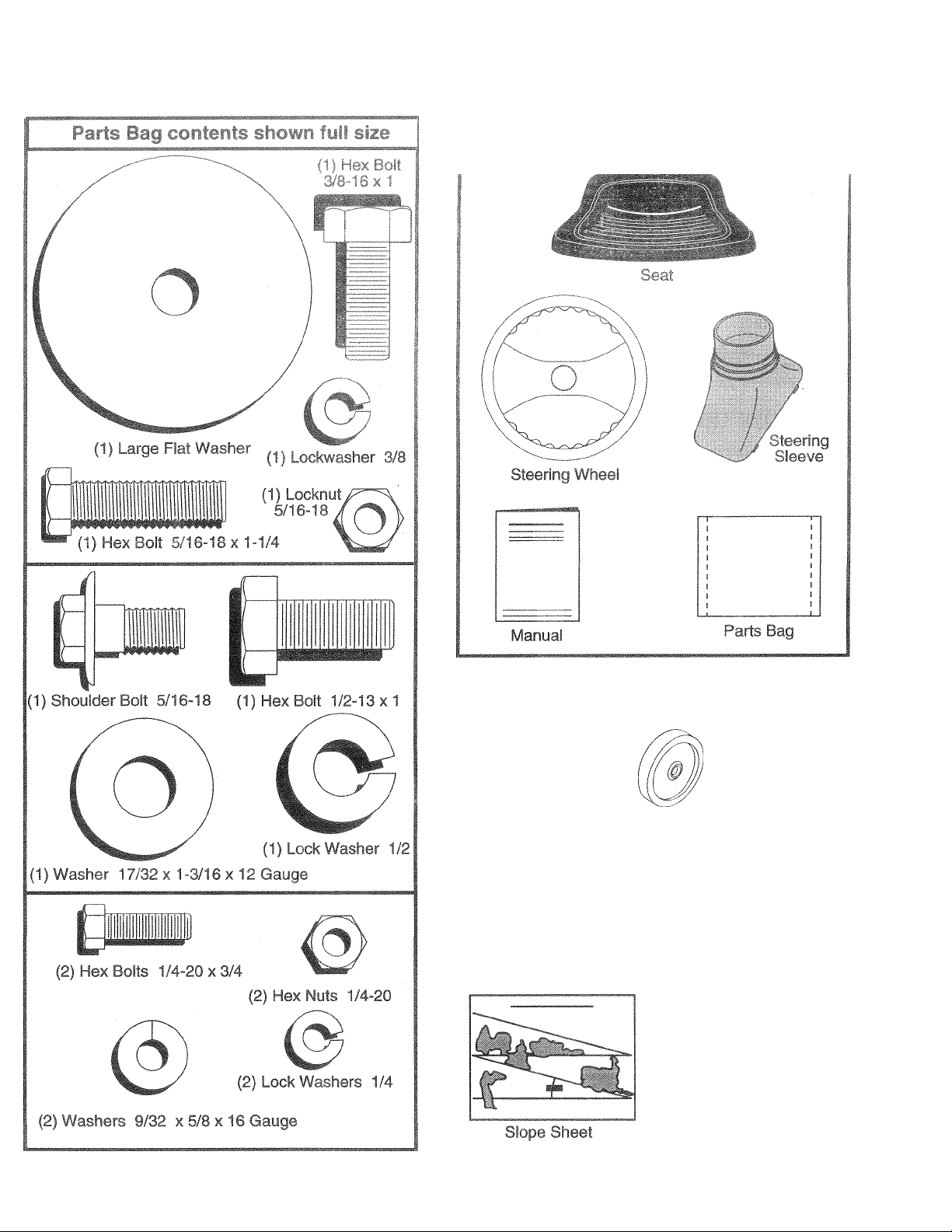
Parts bag contents not shown full size
S
(2) Shoulder Bolts
(2) Washers 17/32
X 15/16 X 12 Gauge
(2) Gauge
Wheels
(2) Center-
lock Nuts
@
(2) Washers 3/8
X 7/8 X 14 Gauge
Steering
Wheel
Insert
Steering
Extension
Shaft
o
Tznznr
steering Wheel
Adapter
(2) Keys
Page 6
'5 . t-Lait'ii
TOOLS REQUIRED FOR ASSEMBLY
/ •• P- b -1 p'i 1 , , . . , :
K‘l nch SI, L -,h *
3/d" y^Lk;! i I " I < litt till, y Hills
(2) 7/16" wrenches Tire pressure gauge
(2) 1/2" wrenches
(1) 9/16" wrench
When right or left hand is mentioned in this manual, it
means when you are in the operating position (seated
behind the steering wheel).
TO REMCj¥t 1 Hht TUR FROit CARTON
UNPACK r ASTON
• Remove al! accessible loose parts and parts cartons
from carton (See page 5).
• Cut, from top to bottom, along lines on al! four comers
of carton, and lay panels flat
® Check for any additional loose parts or cartons and
remove.
eption of th'
and hardwa
il I > f dl~ ’ ! |.l' l( i'jSO>
amble must be iiqhtened securely. Use
BEFORE ROLLING TRACTOR OFF SKID
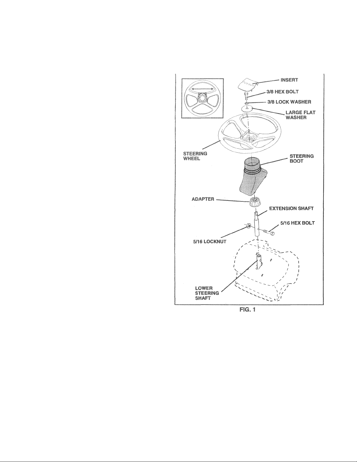
ATT*w*,H TTFF.PiPC WHFFb Fig. 1)
L it V-L N Sil/CT Ai.u L’> Hi
e ori '.hah Oi'f- Vs/V ifc iipg.>-hifl /-lign
nrmii.ro II ' shat'', t^nd
-t.shiil O, I , i I, ,',t (l t , 'T t. .’•cru II SL- Ul'ly.
IMPORIAMi TH HT. .i Bt.LT/f<r» i\iUr i hCl'Rl I - TO
16-2.. FI. Lb.1 I„RQLL.
• Place tabs of steering boot over tab slots in dash and
push down to secure.
INSTALL STEERING WHEEL
• Position front wheels of the tractor so they are pointing
straight forward.
• Slide steering wheel adapter onto steering shaft exten
sion.
• Position steering wheel so cross bars are horizontal
(left to right) and slide onto adapter.
• Assemble large fiat washer, 3/8 lock washer, 3/8 hex
bolt and tighten securely.
• Snap steering wheel insert into center of steering
wheel.
• Remove protective materials from tractor hood and
gri.L
IMPORTANT: CHECK FOR AND REMOVE ANY STAPLES
IN SKID THAT MAY PUNCTURE TIRES WHERE TRACTOR
IS TO ROLL OFF SKID.
TO ROLL TRACTOR OFF SKID (See Opera
tion section fot location and function of con
trols)
• Press lift lever plunger and raise attachment lift leverto
its highest position.
® Release parking brake by depressing clutch/brake
pedal.
• Place freewheel control in freewheeling position to
disengage transmission (See ‘TO TRANSPORT” in
the Operation section of this manual).
» Roll tractor backwards off skid.
• Remove banding holding discharge guard up against
tractor.
Page 7
HO^
CONNECT BATTERY (See Figs. 2 and 3|
CAUTION: Do not short batterf termi
nals by al ¡owing a wrench or any other
object to contact both terniiiials at the
same time. Before connecting battery,
remove metal bracelets, wristwatch
A
< t > *1 I t, n
first to prevent s
tal qrounding.
TKM
SEAT
PAN
BirTERYBOX DOOR
lire
p.i.i to ; I '. I 'tt .I
® C'pf ri i»{> J< i .(h wiii i.i- f t< 1i. r I ¡riSiic.
¡it! ai• H i-c ^ 1?.' I
• R- ft Ji- : nn -,^1 f fct f fi I ' u vrt ' f •']
• l‘'ih. h-*Ter. .' |.i!: ,11 fc ^ir 'll ' I a.f.ver
irdsta!. a on l-t-> iinL«-! .uoateo r.-tu'cen i-tr,'na*s)
chaty' b. tif n- fo' ,aiiH‘r!iiim ot or<- noyrdtC-'Cj .-mps.
• First ccnnect ril-[ 10 ittcivcc.blpt( fo.itn (+) leirninal
With tiex bC’lt 1at luc> Wu. h‘o' -.nd hex nut as
sh? T rpht'> .a!/
• Co» nect BLAGF yr>un>Jrg cabi- to negative {) termi
nal with rcrmininy b-\ bait, flat vasher. iock washer
and hex nut Tight'-; i r,t< ureiy
• Close battery box door.
Open battery box door for:
• Inspection for secure connections (to tighten hard
ware).
• Inspection for corrosion.
» Testing battery.
• Jumping (if required).
• Periodic charging .
DISCARD
TERMINAL
PROTECTIVE
CAPS
LOCK
WASHER
FIG. 3
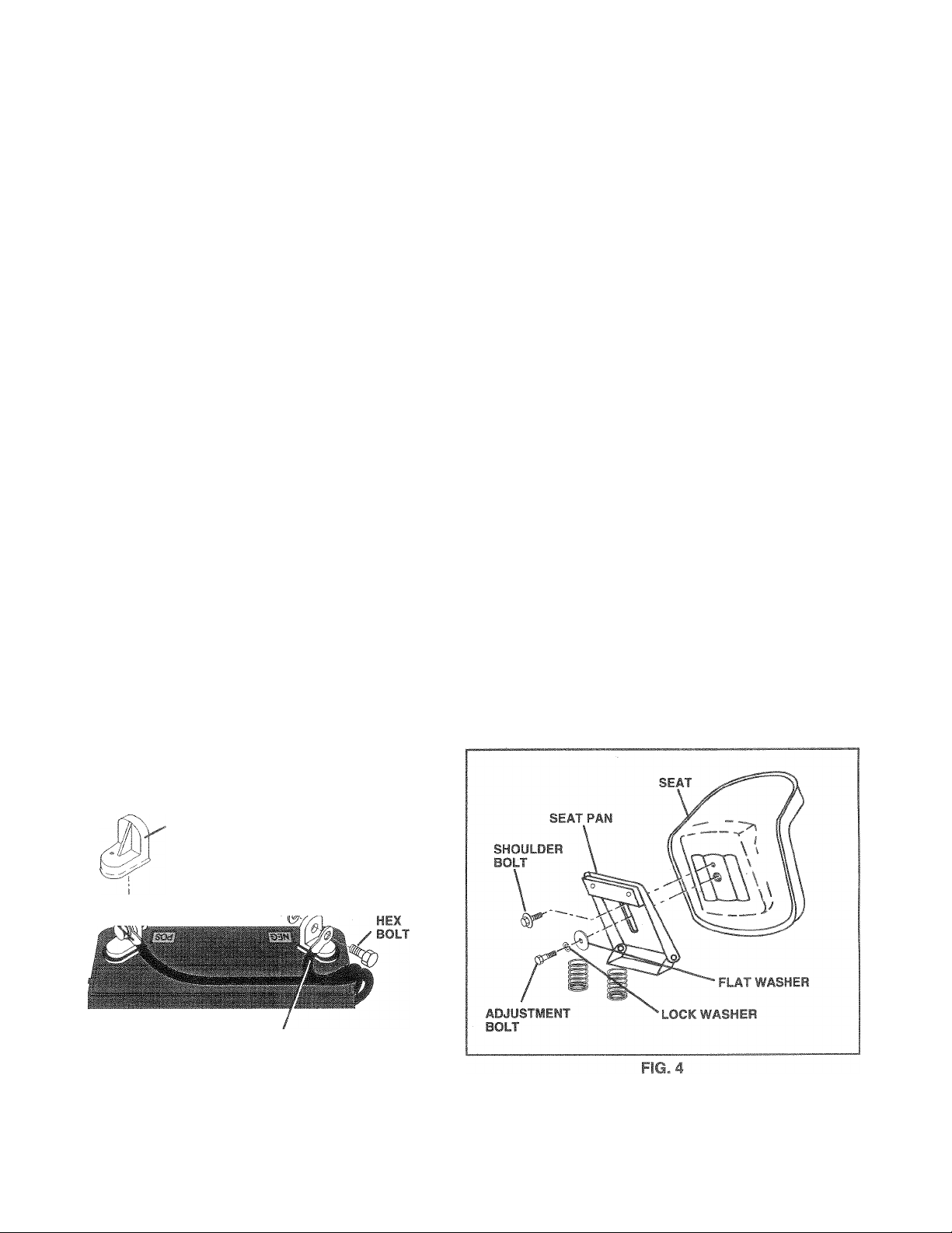
INSTALL SEAT (See Fig. 4|
Adjust seat before tightening adjustment bolt.
• Remove cardboard packing on seat pan.
• Place seat on seat pan and assemble shoulder bolt.
• Assemble adjustment bolt, lock washer and flat washer
loosely. Do not tighten.
• Tighten shoulder bolt securely.
• Lower seat into operating position and sit on seat.
• Slide seat until a comfortable position is reached which
allows you to press clutch/brake pedal all the way
down.
• Get off seat without moving its adjusted position.
• Raise seat and tighten adjustment bolt securely.
POSITIVE
(RED) N
CABLE
HEX
NEGATIVE
(BLACK) CABLE
FIG. 2
/ FLAT
/ / WASHER
Page 8
t
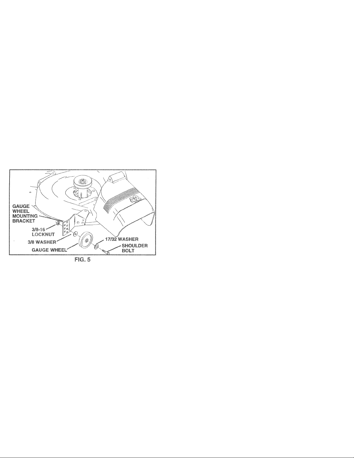
ASSEMBLE
S TO MOWER
DECK (See F
Th6 gauge wheels are designed to keep the mower deck in
proper position when oporHiing mower. Be sure they ar©
properly adjusted to ensure optimum mower performance.
“ eriir'k icMr* v^n<-m i.i!!'- i,,jf i:- on a Tk-.i le^ei
surface.
^ Adju r wei n i uni'*' f''ight iGte B ’ AD
JU ! vDiAf--- o‘J'r.-'ID td k s f”iiiih< Di^diic.H
seciior uf ihb rriariuai'
Wit i i.w-r ii. 'i.-j , ,1) .s dipt .itiori, ('myp
wifm A'hf.uidL^. Lit Ju ait/di' lignPyoff tiie
uio ml ¡0 *f! {^ai ,w I -pprrpfi ie hfk with
TiuiLcriiJi 1 f.f / * *i,i ,aod3/.i it?
lorKiiiit ! J tipi. < *. t. • i -ly
® Repeat i(.i ,,M .t -iJf inslalliiip gauqe wheel ¡n
same adjustment nose
CHECK TIRE PRESSURE
The tires on your tractor were overinflated at the factory for
shipping purposes. Correct tire pressure is important for
best cutting performance.
• Reduce tire pressure to PSI shown in “PRODUCT
SPECIFiCATiONS” on page 3 of this manual.
CHECK DECK LEVEL NEC >
Forbesk uiiing itít-uIR mnwe. luu'icj í.-jüiíJ be properly
leveled. Fee "Tf < 11 to L MC W. . ■ ICfSiNG” in the
Service and *diuctmr h seciic i r i ’hss manua!.
;he "EM
After you learn how to operate your tfHCtor, check to
that the brake is properly adjusted. See “TO ADJI
BRAK
manui
BEFORE 'Ai wJR and EMJO) yOUR NEVV
.. ^ o , i W A D.f -. >A1 SL'ftt I HAT YOU RECEIVE
ih!t Of - I f LhK: TViu./AV INlfYAilEFAC NON FROM
TN! m.-i /iCcTilif I
Fit - ’ ^UOyi‘h • / . •!' s 4T/Mw C hb\ hi li F
/ Mu r*-fii 'i'll,II. parl.T in rartoo
A lirtif ri 1 iirupcit, pippoff-j ahu charged (yinimum
/ dealt 3djiictea-'Oinforiably and tightened securely.
/ tiie* are properly inflated (For shipping purposes,
/ be ,-ui6 rnowet deck is properly leveled side-to-side/
/ Cheer mower and drive belts Be sure they are routed
✓ Check wiring. See that all connections are still secure
✓ Before driving tractor, be sure freewheel control is in
WHILE LEARNING HOWTO USE YOUR TRACTOR, PA Y
EXTRA ATTENTION TO THE FOLLOWING IMPORTANT
ITEMS:
/ Engine oil is at proper level.
/ Fuel tank is filled with fresh, clean, regular unleaded
/ Become familiar with all controls - their location and
/ Be sure brake system is in safe operating condition.
/ It is important to purge the transmission before operat
n the Sen/ice and Adjustments sectiori of
,.i< ' ,r t ly tii 1“ bi-F", f ruripleiMj
the fires wer-“ overinflated at the factoiy).
ftor.Ho-et-ar tor Do't CiJtdng results. (Tires must be
nrrpArly inflated tr.- ievniing)
piopfciiy a>our.d pulleyo :itiu in^kje ail belt keepers.
and wires are properly damped.
drive position.
gasoline.
function. Operate them before you start the engine.
ing your tractor for the first time. Follow proper starting
and transmission purging instructions (See‘TO START
ENGINE” and “PURGE TRANSMISSION” in the Op
eration section of this manual).
CHECK FOR PROPER POsITS TN OF ALL BELTS
See the figures that are shown for replacing motion and
mower blade drive belts in the Service and Adjustments
section of this manual. Verify that the belts are routed
correctly.
8
Page 9

These symbols may appear on your tractor or in literature supplied with the product. Learn and understand their meaning.
1.
BATTERY CAUTION OR
WARNING
REVERSE
FORWARD FAST
Tt (J-
r-;
ENGINE ON
fi
FUEL CHOKE MOWER HEIGHT DIFFERENTIAL PARKING BRAKE
ENGINE OFF
.^l
R
OIL PRESSURE
N
CLUTCH LIGHTS ON LIGHTS OFF
^ ©
LOCK LOCKED
H L (®)|I
la
REVERSE
NEUTRAL
HIGH LOW PARKING BRAKE
SLOW
a
UNLOCKED
t
if
MOWER LIFT ATTACHMENT
CLUTCH ENGAGED
*
m
■
r
DANGER, KEEP HANDS AND FEET AWAY
ATTACHMENT
CLUTCH DISENGAGED
I—
— =/<»*
HYDROSTATIC FREE WHEEL
(Hydro Models only)
IGNITION
= im
Page 10
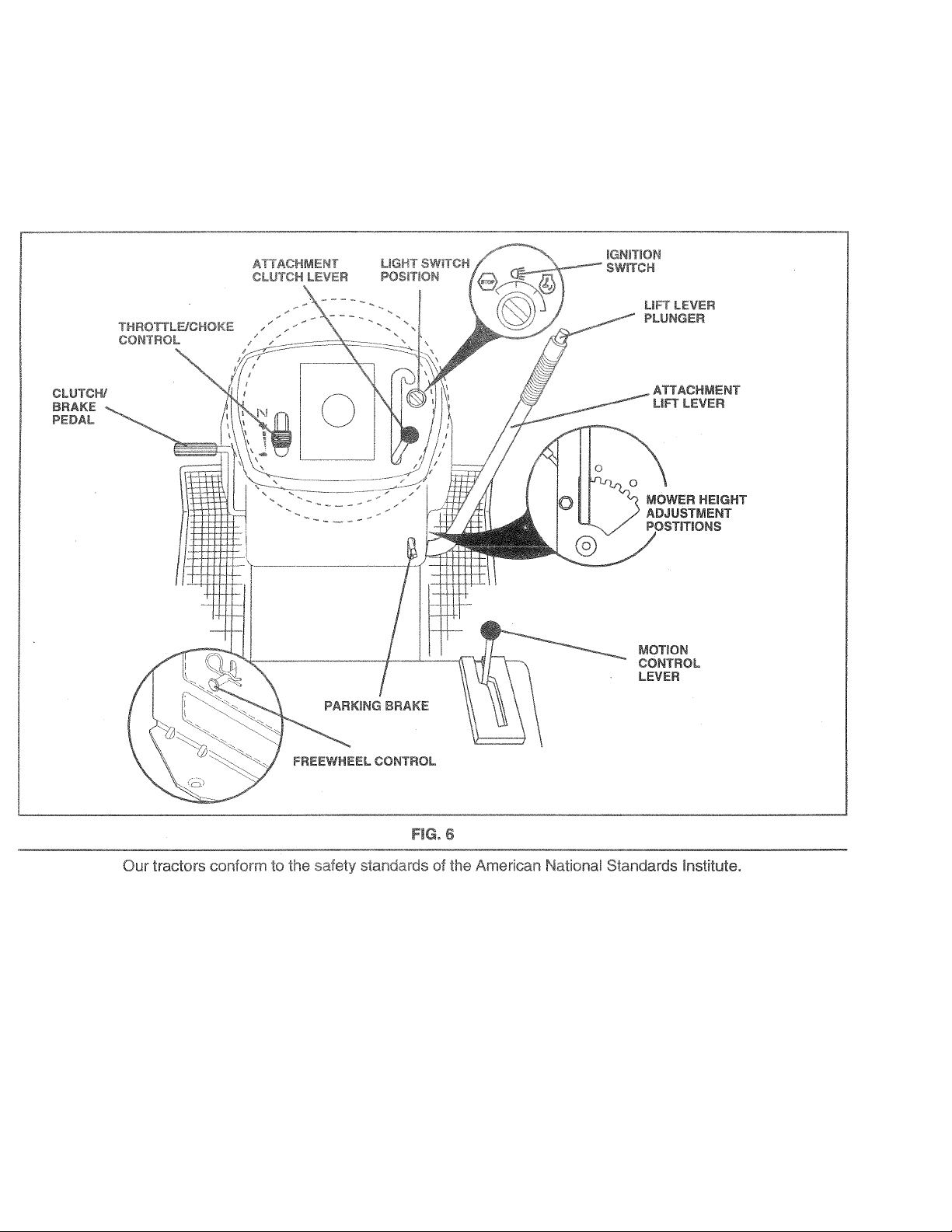
KNOW YOL
OPERATION
ATTACHMENT CLUTCH LE¥ER: Used to engage the
mower blades, or other attachments mounted to your
tractor.
LIGHT SWITCH; Turns the headlights on and off.
THROTTLE/CHOKE CONTROL • iJsed fcr staling and
controlling engine speed.
CLyTCH/BRAKE PEDAL; Used toi -JteiLtching and
braking the tractoi and starting trie engine.
PARKING BRAKE: Locks dutch/brake peda! into the
brake position.
MOTION CONTROL LE¥ER: Selects the speed and
direction of tractor.
ATTACHMENT I ¡FT LE¥ER ■■ Used to raise and lower the
mower deck or other attachments mounted to your tractor.
LIFT LEYER PLUNGER; Used to release attachment lift
lever when changing its position.
iGNiTlON SWITCH: Used for starting and stopping the
engine.
FREEWHEEL CONTROL - Disengages transmission for
pushing or slowly towing the tractor with the engine off.
10
Page 11
^3
i riATrr^-f-!.
The operation of any tractor can result in foreign objects thrown into the eyes, which can
result In sewere eye damage. Alwe fety glasses or eye shields while operating
your tractor or performing any adjustments or repairs. We recomme ide ¥lsion
safety mask ower the spectacles or standard safety glasses.
... H. y
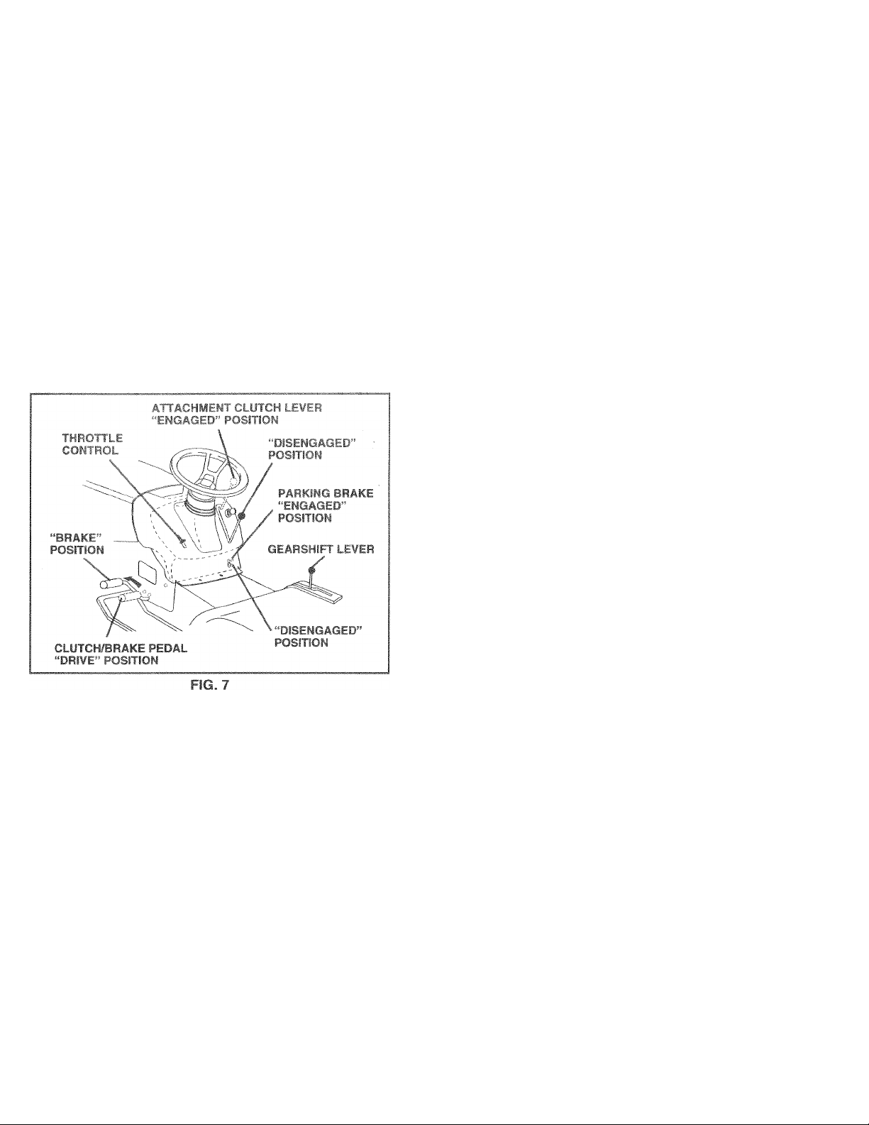
w-mif ^ J caking . :K , ‘ g. 7|
Yourtractor is equipped with an operator presence sensing
switch. When engine is running, any attempt by the
operator to leave the seat without first setting the parking
brake will shut off the engine.
* Depress clutch/brake pedal into full “BRAKE”, position
and hold.
• Place parking brake lever in “ENGAGED” position and
release pressure from clutch/brake pedal. Pedal should
remain in “BRAKE” position. Make sure parking brake
will hold tractor secure.
STOPPING (See Fig. 7)
MOWER BLADES -
• Move attachment clutch lever to “DISENGAGED” po
sition.
GROUND DRIVE -
• Depress clutch/brake pedal into full “BRAKE” position.
• Move motion control lever to neutral (N) position.
IMPORTANT: THE MOTION CONTROL LEVER DOES
NOT RETURN TO NEUTRAL (N) POSITION WHEN THE
CLUTCH/BRAKE PEDAL IS DEPRESSED.
ENGINE-
• Move throttle control to slow {«^) position.
NOTE: Failure to move throttle control to slow
position and allowing engine to idle before stopping may
cause engine to “backfire”.
• Turn ignition key to “OFF” position and remove key.
Always remove key when leaving tractor to prevent
unauthorized use.
• Never use choke to stop engine.
NOTE: Under certain conditions when tractor is standing
idle with the engine running, hot engine exhaust gases may
cause “browning” of grass. To eliminate this possibility,
always stop engine when stopping tractor on grass areas.
CAUTION: Always stop tractor com
plete 3ve, before leav
A
ing the operator's position; to empty
grass catcher, etc.
Gi USE , Ki Y • ,1.1 wKd iTROL (See Fig. 7)
Always operate engine at full throttle.
• Operating cingine at less than full throttle reduces the
battery charging rate.
• Full throttle offers the best bagging and mower perfor
mance.
” PmVI Fi SRWARD AND BACKWARD
(O« Flq. 'I
The direction and speed of movement is controlled by the
motion control lever,
• Start tractor with motion control lever in neutral (N)
position.
• Release parking brake and clutch/brake pedal.
• Slowly move motion control lever to desired position.
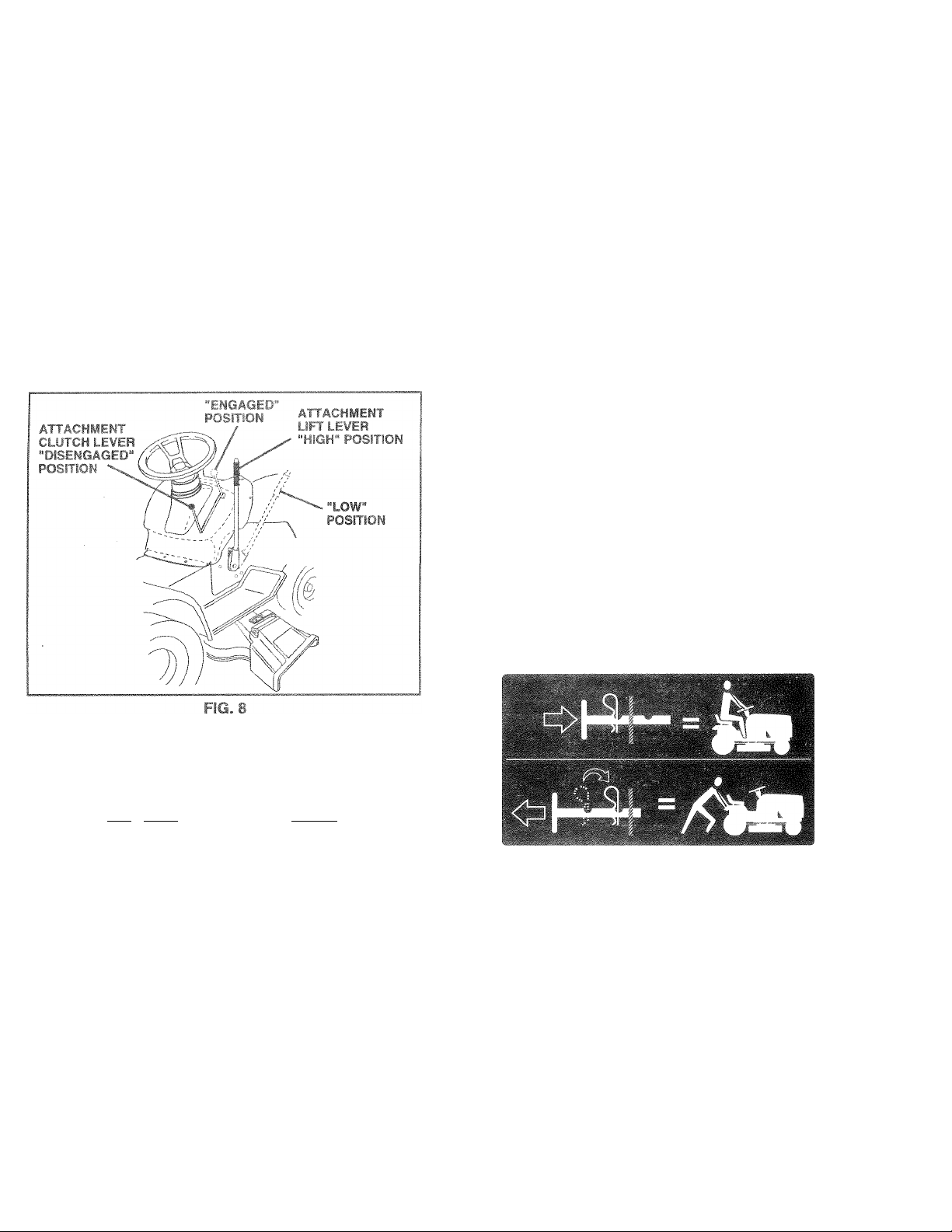
TO ADJUST MOWER CUTTING HEIGHT (See Fig. 6)
The position of the attachment lift lever determines the
cutting height.
• Grasp lift lever.
• Fress plunger with thumb and move lever to desired
position.
The cutting height range is approximately 1 -1/2 to 4". The
heights are measured from the ground to the blade tip with
the engine not running. These heights are approximate
and may vary depending upon soil conditions, height of
grass and types ot grass being mowed.
• The average lawn should be cut to approximately 2-1/2
inches during the cool season and to over 3 inches
during hot months. For healthier and better looking
lawns, mow often and after moderate growth.
• For best cutting performance, grass over 6 inches in
height should be mowed twice. Make the first cut
relatively high; the second to desired height.
11
Page 12
»ERATE MOWEP
'.ЭХХ rnower
то STOP MOWER E
лОм f-4i '
'„•i'O* L.r
)'<,R i.iíf"-( -Г,- ‘ ! Л» - cjfrhe-
\Á
L- ‘‘Q-1'^Зтт ^ '■A
] ne
witf
. . . >'ll< 1^ * * llCf!
• , « , ' Ч- Esti ni
_
1É«‘
¡ "Л T«'-
^GINL
*1
)if with tractor on level ground.
-' <R > ( , . >11 i i^r
removí
i
To
tie
ь ^ 'F: E i 44 h .rja. R dl«, w |
WMЧ.'jM-Tih. , > I i,. ,. nil liw-4.twt.ur t •dteongage
triiii..i, . I 1 i.io -M 4 ¡,4-1 4JI 411 .-1 ireewneeling
|{i£i. .. n--I i. r>'> и,'-. 1И'J - lii'6 iw i drawbar
Ui tini
‘ i : ' I ‘ I s Л,. Ii I t 4 . F 1 position w'lth attach-
• ‘ . 1* к - ill I
■' I :r'dhi!(l ih position by
r-. ii44 t 1 и ' i.-n I ,n f'-ijA-rd h'^le of control
i d
'• i 1 . Jl t ,44 . , i W, , d ¡.|>'> - th'»n two ( \ЛРН.
> ■ i (/-' i ; f •! . ' ..ds opl until
J, t./ _*•
> i. V . V'.. ■ a . s T ilnr monua!).
I . r , i> ' •■w .rrtf f R--p'nsibili-
his manual.
' nSjll I z )( \ .^kLOIld..,
4 .1! 0 u Ji ,1. uvjnge oil fc"'
” i ^ ' -E-RT in thfc
e Fig. 12)
31J
shipped, from the
! J.i .¡i
W
1 [ -it . I i- h, v'f picK edure.
NOlr. , ( '< ' s , i, ‘,'iijOF worn transporting
your!-" ^ I * n-' ' 4 i .'f , W 'J4 os .d IS closed
n>J ' 1 ' " . 1 --it lop.1-4 • I-.n-uf tying
iiOoJ . I ■ , I ,
ТО OPERATE ON HILLS
caution 00 11, drivF up or down
Á
» • hoij ' tri! w I I. !’ i fift! tir f down
hills,,
• / ti J Id, f il'< 't > ' < • 'is h!'l
» 1 itrf'inp !► ' s, 1/ * ' n i f' •' erto
Id %r r I O'ilr '
• f "-to^piiiq ic D< i|, d|^ii , f If’!,! itdn/hrake
pedfcl qu'ckl) h hr e pc iiiii ano » < laCft- parking
brake.
» flit v'l r'*tir.i3 t.ji.i f i lo'< I I Ik ./ifS!'R* j caiiu >.
IMPORT i". IHr MOliO WOMiTiOL WVL, i OES
NOT HEIU! (J Tr) .JEU7-V L 'K- : «,'* > i ,> it'' wribR THE
CLUTOH/F RAI- F i H'^i- RT ht Fu
» fn fM ihmoveifirn siovi <'leds-p kiiigbiakeand
clutch/brake pedal.
« iaiowiy move rrioiion coniroi lever lo siowesi selling.
» Make all turns slowly.
hills with slopes ^iieoifei than 15° and
_Jo rtL.t driVL £ ? tope.
12
Page 13

fet'âî
•D G
m
SOLINE
Fill
fU6
oasc
and
Pure ise fuel in i
days5 IC
ORT
ow
BE
ï. "J i-ii
SOLINE. TO HELF^ INSURE C
STARTiNG.
tU' ■■' -f t 4 •' L-i I<1 <n:.f' ■ I r<-K. «I“'' ' rJi
1. k . vk/ gas t J'- 'î' >r. ><jî s» i
il tank. 1
llir lewitham
le wi!l inerì
rpi
due© vslvc
ì assuro ft le! freshnes
IT* WHE^
32''^F(0°C), U
' ' t ' (If - >tij. -1' - ilj, i - ' >h , *■ K f d
' !'>lt r vil I' ;'i t'< 'i ,r^íh~, r. <‘ ¡1'.!. I
Jse fresh, clean, regular unleaded
inifiium of 8 7 octane. (Use of ieaded
1 and lead oxide deposits
ì fife). Do ì
QuantitiBS II
4 OPERATING IN TEMPERATURES
SE FRESH,
not mix oil with gasoline.
lat can be used within 30
■ t 'l-.il ‘IS . 1 /'. i
300D COLD WEATHER
oyStCn li -.n r» '51 .s Vk'lç in 'J-raÇ; 1_. •_!<'- jMf
pi'Urn,' a t,. „,-cl=!<i vt Oui-) btCI ■ I.Jun i i
acjt J f if.aqei. l/talr'ff^^ îjc.. t ni' i tie
trifji« ^ ~rii 1' If iTi untii [lif* in'-f Hif V .«lu .-'rtt.'.' ' . e
urfip{> Ij^u re^f inai 1,^/1 iea&i'p kac Ctar.«.3 !ri î'uc
tioria tor :oiitiGii3Î Ttforrnaiior. Kfcva: uto r-iior! or
carbnrer.i dtarier p'u'jsiots iri tne îue! kn» oi s «erri i aient
damagt- la, occ'Jt
CÄÜTIOH- FÜI to bottoi« of gas tank
filier r»ecl< DonoiowerfilL Wipeoffany
A
spiiieo oii Ol fsjei, Co not ¿tore, spiii or
use gasoiine near an open Harne.
TO START ENGINE (See Fig. 7)
When starting the engine for the first time or if the engine
has run out of fuel, it will take extra cranking time to move
fuel from the tank to the engine.
• Be sure freewheel control is in the transmission en
gaged position.
• Sit on seat in operating position, depress ciutch/brake
pedal and set parking brake.
• Place motion control lever in neutral (N) position.
• Move attachment clutch to “DISENGAGED” position.
• Move throttle control to choke (|\|) position.
Note: B
procedur
• inser
tion an
posit
not fl
onds
sev8
in -
.i .. ....
t ?P it--.
diok
VVA' > f ’
i/f. m f(
I ‘ pi ti-
The attachments and ground drive can now be used. If
:'K ,I.;I i ‘3 ' t U. . f.TF‘< ' , t_ ! t , t- G. ,!i't
in'i '¡A '*'.11 r'r* up i( rc t. --iiiM I F, tfii'- hth
*1 ADH !l IN { ',o f ,a
e Whi-rn I'Uir .stall -Jl ruit '«!i' Ti fhmttle
icftfoh- I = chok.. f|.« i) p'/iAu-uoti tti'-uig'ot mi s
rougfily. illon I.' evn ffir tilt iTc'tiol t« I -a i%) pocition.
Thio reguiff an tugin«. Act.ii up pp«tio>J from
i-e/pial teccrios h -tvomTniir tnes depending nr, the
tempeiaiijr*-
HYDROS’^* ' '*d ' I *F
• Before drivinq the unit ir cold weather the transmis
sion 5rn.-uicf Of j.orm.id jp roilov^i
• Be sure the tractor c on level ground.
- PldCb the motion conliol lever ii« rieutral.
Release the parking brake and let the ciutch/brake
slowly return to operating position.
• Allow one minute for transmission to warm up.
This can be done during the engine warm up
period.
• The attachments can also be used during the engine
warm-up period afterthe transmission has been warmed
up.
NOTE: If at a high altitude (above 3000 feet) or in cold
temperatures (below 32 F) the carburetor fuel mixture may
need to be adjusted for best engine performance. See “TO
ADJUST CARBURETOR” in the Service and Adjustments
section of this manual.
starting, read the ws starting
)r© îriân îfîi©©n
joes noî start
tnroltic
I Try aga
I i t ‘t 1 ji di I s 1.1 i. ' I
rts, move the throttle control to the fast
/ •' € • 31 / II •'
alf
#)
{^)
Û etili
Page 14
PIJRCsE
lUTIOD
I "
To ensure profзег ope!
mended that ttle transi
tractor for the
trapped air inside the I
> f.ec d JH,.G .
itel'DI-1 i in rO ,
RLc/<
SHR ‘ r L ^ PURG
EEH.toA fH- i THE TRACTOR.
• Place tract
[JuRlhp r.i rU ( 1
D[ etnn. lission
in rt-t
ir<i: sfcc.»i j 11 f man m¡i
wstt'li s in ifciClli tBái OcU’
ifiurriin^ «Tio-e ihraill- , ■• it j’i-j •,! л pjsiiinii.
\N>*h moti')..f r,iitrol i. '0 ni> ii= >/t 'li !| pi-sii'o i biowiy
diben>*!iyr . I Ich't A <i .
» Move nofiLP cj’^i 'J !•_ 00, ‘ 1 ■ Mr /-ic p sri in and
hu.d lu. i . ^ p-, M • 1 ■ 1 « mo I' V) uli •' /erse
posilicn 3iid • f.lo f',r ii\i. Г'} ' -/■ r. *0 Reporf this
proM -Ui' idi. I m ft -* ■
NOTE:') rifipR! p'O"«-c< i-m n irio/ementof
drivew'-m-ls •'■’o mi' >' ii-:-ulicdnve
system.
® i 1; ' v'i.ri,vii. •- ;i i'r rR|H)i.i. ton .Rnul
afleriiiii- r.m г-1 p'! !' ’M :
• t ,<y jf ii-II.Ml к ' ' pi 'dlfcCb,fjnirt!| ii'
dri-'-ru-JOS Ouf \ •_ S "R ei titCA: ir. ch - section
Ol П tea! ilidl
• Sitting i.dhtJu'c-ic. .o-mit ; s • pi.i'-. A-tu Iheengine
is running, ills.“ mfOiilr t' i' tc hall speed.
W'lth not ((I f 'n'lrn^^vtf » I'cuiibl (П) posit.on, siowiy
discriU'uie cJumh/bi k~''Ю J
• Snwiy iTOiV'-t tTioiion m iif i к /ei fom ... i after the
tractormovi' apf.riKi.nalii, л- (i. leei &,owiyrnove
motion foniro! к лег to r< >■ r*. i' i юг. After the
traUi I rrioves apfroximai ,S n-e f i feei return the
rr*o ion control R'/f I to ii le Ч 'Fmj (1'!лЮы1'оп. Repeat
this procedure with the motion control lever three (3)
times.
• Your tractor is now purged and now ready for normal
operation.
riQ*
first tirni
lipping c>f yOUi
DR SE RVICI
or safe!)
«ling p<
1“
'0r 0ilQ3Q© or diS€
I ievei“While tile engine
’âîlOn «
snd porforrnsncB
rfiissìOn be purged befor-e operating
В, Thi is procedure will n emove any
ransmission which msy t lave devel-
D YOURTRANSMISSIOt
lED / ATER REINSTr fLLATION
/on le^/ei surface with eni
3sîtîon
tfrirtor
E OR REPLACE WENT, IT
' i J U '
' H ‘ n
.
....
' p
it is recfjm-
•J REQUIRE
line off and
-t-R ,1 Trol
D! f . r ii,
ií., m,, '^iig ne
ШШШ
Tire d when 1 nq IS
B
min
Огл
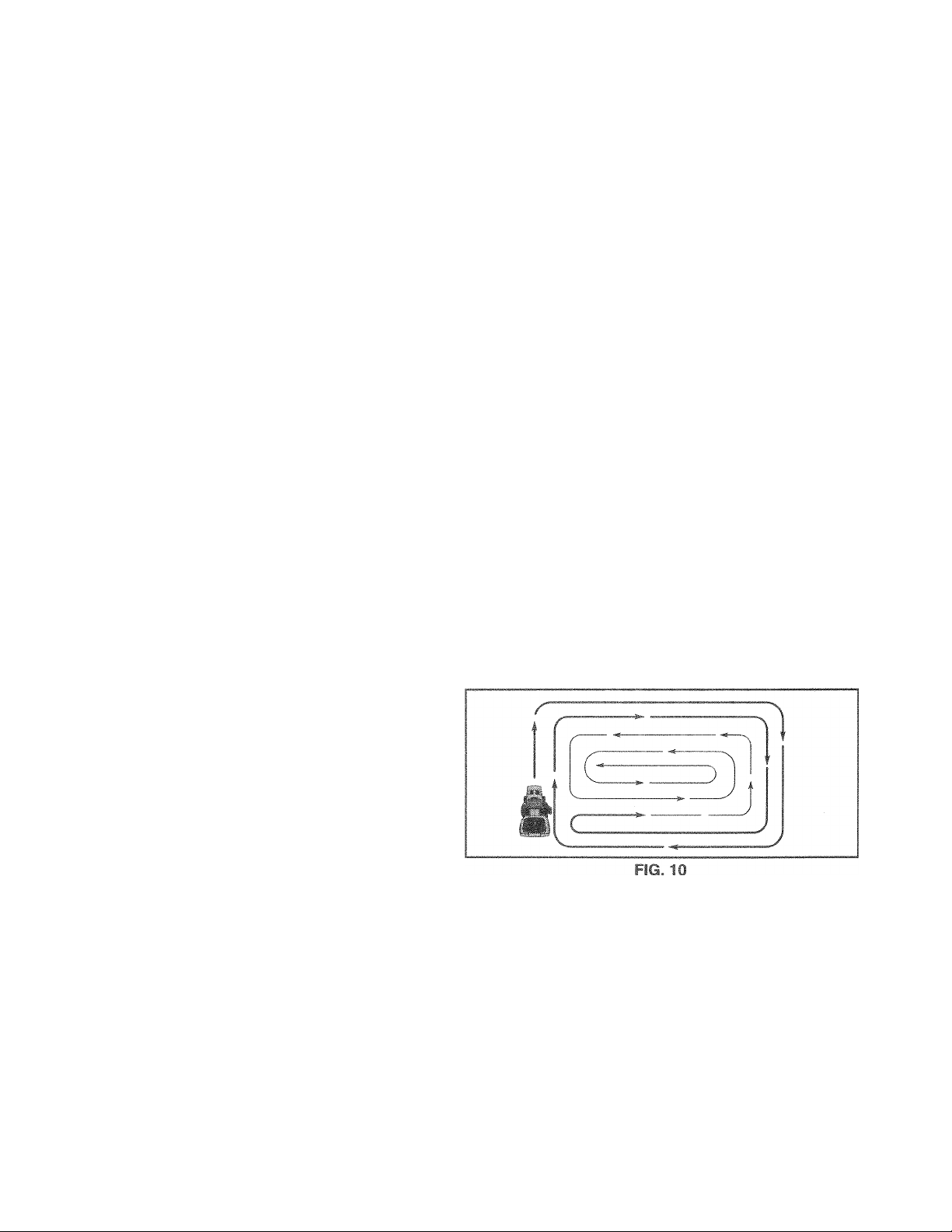
.. ,i I , p- f n ,|. 1-1 ihf-, L’' -ir-d '0 thp right of the
'J 111 1 ill u'l T. . I! o ' evrii P.stnbution rf
ii r m, »1 mo o (1* r'm, r ihr-g
I ij| . kpproi Will di?rh'-tgs away from shrubs,
,»ro- r-/- Hfti or e cr two riiUiids, mow
-1 tm pp">„te direc tiun mak'ng Iftt hand turns until
W h> d f ‘ I j 10)
|] grass i oi-ht i. w.v tali, it shi iiid be rriowtd iwicp to
r&ciK *'■ lo,.d .-..i f cssible tire ha...ard fron. dried clip
pirg. Maro f r-t mj- ■'elath'ely high, the second to the
desired height.
Do not mow grass when it is wet. Wet grass will plug
mower and leave undesirable clumps. Allow grass to
dry before mowing.
Always operate engine at full throttle when mowing to
assure better mowing performance and proper dis
charge of material. Regulate ground speed by select
ing a low enough gear to give the mower cutting
performance as well as the quality of cut desired.
When operating attachments, select a ground speed
that will suit the terrain and give best performance of
the attachment being used.
)ulci b
left hand
Id >1 I !if' inq j J. • i<-r.jpd i,nm the ima
p
4
r ‘ »vfi /iF.iHR.'- T!f. in
Adjustments
Í- , -íH'i'i'lbt Ifif intri-
lici- .ir-M- o.-art lyming tuifie nghi
*► I f ■ Iji il.uV'ltiCj
ition of this manual.
14
Page 15
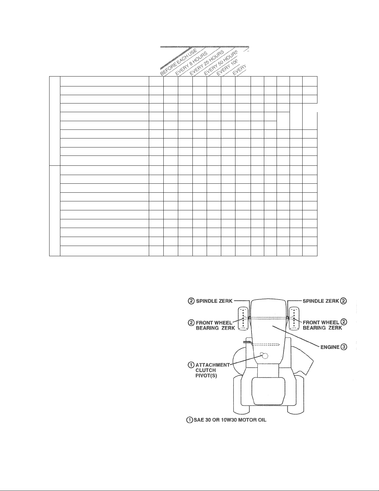
IIAINTENAWCE SCHEDULE
FILL IN DATES
AS YOU COMPLETE
REGUi^n SERVICE
Check Brake Operation
Check Tire Pressure
T
Check for Loose Fasteners
R
Sharpen/Replace Mower Blades
A
Lubrication Chart
C
Check Battery Level/Recharge
T
Clean Battery and Terminals
0
R
Check Transaxle Cooling
Adju.st Blade Belt(s) Tension
Adjust Motion Drive Belt(s) Tension
Check Engine Oil Level
Change Engine Oil
Clean Air Filter
E
Clean Air Screen
N
Inspect Muffler/Spark Arrester
G
1
Replace Oil Filter (If equipped)
N
Clean Engine Cooling Fins
E
Replace Spark Plug
Replace Air Filter Paper Cartridge
Replace Fuel Filter
1 - Change more often when operating under a heavy load or in high ambient temperatures. 5 2 - Service more often when operating in dirty or dusty conditions. 6 3 - if equipped with oil filter, change oil every 50 hours. 7 4 - Replace blades more often when mowing in sandy soil.
✓
✓
✓
✓
✓ 4
✓
✓
✓
✓ 5
✓ s
✓
✓
1^2,3
✓ 2
✓
✓ 2
✓
SERVICE DATES
✓
1
✓
✓
—
—
—
✓
✓
✓
If equipped with adjustable system.
Not required if equipped with maintenance-free battery.
Tighten front axle pivot bolt to 35 ft.-lbs. maximum.
Do not overtighten.
GENERAL RECOMMENDATIONS
The warranty on this tractor does not cover items that have
been subjected to operator abuse or negligence. To
receive full value from the warranty, operator must maintain
tractor as instructed in this manual.
Some adjustments will need to be made periodically to
properly maintain your tractor.
All adjustments in the Service and Adjustments section of
this manual should be checked at least once each season.
• Once a year you should replace the spark plug, clean
or replace air filter, and check blades and belts for
wear. A new spark plug and clean air filter assure
proper air-fuel mixture and help your engine run better
and last longer.
BEFORE EACH USE
• Check engine oil level.
• Check brake operation.
• Check tire pressure.
• Check for loose fasteners.
LUBRICATION CHART
©GENERAL PURPOSE GREASE
©REFER TO CUSTOMER RESPONSIBILITIES “ENGINE” SECTION
IMPORTANT: DO NOT OIL OR GREASE THE PIVOT POINTS
WHICH HAVE SPECIAL NYLON BEARINGS. VISCOUS LUBRI
CANTS WILL ATTRACT DUST AMD DIRT THAT WILL SHORTEN
THE LIFE OF THE SELF-LUBRICATING BEARINGS. IF YOU
FEEL THEY MUST BE LUBRICATED. USE ONLY A DRY, POW
DERED GRAPHITE TYPE LUBRICANT SPARINGLY.
15
Page 16

TRACTOR
Always obsep/e safety rules wh
BRAKE OPERATION
if tractor requires more than six
at high speed in highest gear, th<
(See “TO ADJUST BRAKE* ir
f!if UÍS .xe>4ip ti .-i! i.i.MiUa/
11NE,;
*' Mi • i n qf lO'- S ; Í. . 1
UCT SPECIFICATIONS” oi
Keep tires free of ¡
cals which can hs
soline, c
■ih
A\c-d ..iiiip'^ tnrr I
OÍhí-r If'.. . id (f r It.r
NOTE To .fcO'iiL pijivju CL li. TC .iJfl OiL du^ to
slowleeO .n'-; if„;v O ru» h iron, v )ur local
parts dfc.3!er. iim '^-clí£<nt ¡. t t/eiib lift u.y rot and
corrosion.
BLADE CARE
For best ir.juiif. rnowffer Uhqhs bf kept sharp. Re
place ben: i T 'nibj ;d .Ld> i
зепс
t ri IÍ -< 1Д'- 'fc
Service and Adjus'
I 0!, lit. TO J Р''|‘Л(
•L ■
I I. ... hi .1Ü. I/
'Ч 11 , f . ' '»llpid 4ii-
ruts, sharp objects and
^ > - .-ihioqt
TO SHARPEN BLADE (See Fig. 12)
Care should be taken to keep the blade balanced. An
, i , ■ t . ‘ hr -h, I J ¡1 ' 11-
tual damage to mower and engine.
i . ‘ ' h _i*- ‘0 .-.i I ) III. • " I' I u ;ri‘J'rif|
Vi ( ! ', I .<it .. I If h.<i[ '-III' h.i( or. (1 if mcf.vM
I ' i is to' ■ L ’,.f u-xr) .„'--d 3 t'e" diamstor
^ Th ■' ri - !toj.*toii.tr 'yvhenucngaco'ie
■ I i<,lk « ir,' iii.tmi tiLfi supplied with bal«1 ‘ i
> / -u. f i ..ti.ii *j sL.c.,tapG.iiuiuj!ilifetoeeibolt
M,> . ", h i, pin parallei v*ith the ground,
ii u ' ! L'i "‘<0, >1 J . !J teinain in .toioViaopta!
I>i Ht /’ I oiirioi one f'l ttie bedt moveTi rl.oAinward,
1, 'h' I, in 'y oiio unif the oladt is balanced.
Nc 'h i .1 Ì-* 'ciifm boCriringb'ode Fhelobesof
th', f -i.-j t‘.i h I, ' .ciitoj lO ht f tntcred but are not.
BLADF BEIiO'/AL fSet • I- lu 111
• Rai '(■ mower fc- hiybesc fics 'lion to How access to
. bldf '-if..
® Remm''Tie? ro!t. led war hi s riodct washersecuring
blade,
» Ir'd’ HU (':■ -^ri. f ned hit I r with trailing edge up
tOv> Vrm fW, „ I, n
• 'bTiblf l( hr It ¡ori w U tr tind flat washer in
ex..,a Jidi^r uj she ah.
• Tiqh f 1 boll -- Ji-i'f' ly t30- i m I bs. torque).
IMPORTANT Blrtf.t PCLTL ( i • U T 8 HEATTREATED.
NOTE. VVi-do nt.rv commend sht rp*- ning blade-but if you
do, be sure rhe tfk'dc is baldireu
BATTERY
Your tractor has a battery charging system which is suffi
cient for normai use. However, periodic charging of the
battery with an automotive charger will extend its life.
• Keep battery and terminals clean.
• Keep battery bolts tight.
• Keep small vent holes open.
• Recharge at 6-10 amperes for 1 hour.
TO CLEAN BATTERY AND TERMINALS
Corrosion arid dirt on the battery and terminals can cause
the battery to “leak” power.
• Open battery box door.
» Disconnect BLACK battery cable first then RED bat
tery cable and remove battery from tractor.
» Rinse the battery with plain water and dry.
• Clean terminals and battery cable ends with wire brush
until bright.
• Coat terminals with grease or petroleum jelly.
• Reinstall battery (See “CONNECT BATTERY” in the
Assembly section of this manual).
16
Page 17

V-BELT
operation and repiace if necessary, i ne
adjustable. Replace belts if they begin to sii
TO CHAI
Determin
All oil mu
ENGINE
iperatur
rane
jrvici
)!i Change
siifcatic
TRAiSAXLE COOLING
The fan and cooling fins of transmission sr
clean to assure proper cooling.
Do not attempt to clean fan or transmission w
n ni . ,f' 4 1 ‘,|h 0,r I. . f'<|.f • f >
® Inspect cooling fan to be sure fan blades
9 1 Cf-* I . . 4 I' _).>'• ' fE 'T' . . ‘j Í
if " Í h -iM'.f.f“ I !.
< r ) ' Í, I *ii Í I n gh pici iff.
Cci iiiiU iiii
als, do not use
)rayer to clean
;t ana
other
TRAN;:/i>xr PUMt FLUiLi
Tne trdi'SfL.r't wjc fcs- *ed at »he fact: iv me f|i i'' mainte
nance isi oTn:quir:fdtortnfclite.'ft!ittran': txle * houidthc-
trancadec/“ leer ,, “-ou..< >fr/.ciiig. c» nlact jout near
est cUthr,t:c‘-d sei"Viio ente-/departm* ni
ENGINE
LUBRiCATiON
Only use high quality detergent oil rated with API service
classification SF, SG, or SH. Select the oil’s SAE viscosity
grade according to your expected operating temperature.
SAE VISCOSITY GRADES
Oil will drain more freely when
Catch oi! in a suitable containei
I' ¡»-.r' I Oi il ‘ /( -Jl' к Ft
f>! r • V dirt
to enter the engine when chanc
I ':ii ( V- dO)i. oO '
/>\^.rui '! Ji&'i-ec* ojri.pL't-(
f ^ ..r I
h-lili ■ I qifi ,'iTf Oil tfiroijyb ( il ?,ii d'f Ai'.r OL< Pc>ur
' !ov/h sK* :* errill F ir otpi.')o'.p-.riiy ree
h' r rii-' iF ,f AT'Of I .>1 CO JO » -f this
r -tnoal
io'~ C''(;j.„G»..*iifii!r-;f/dipAirr:icrthi-tHncH 'oL Be
sure dtpsrAl- rap i'- lightened securely tc>i a.'xurate
r-adiri(j Kaci: s)<| at 'Fi ILL liiv cn dipstick
◄
■ ■ -h
=F -20“ 0“
°C -30°
TEMPERATURE RANGE ANTICIPATED BEFORE NEXT OIL CHANGE
20” -10“ 0” 10“ 20° 30° 40°
30° 32° 40°
60° 80° 100°
NOTE: Although multi-viscosity oils (5W30, 10W30 etc.)
improve starting in cold weather, these multi-viscosity oils
will result in increased oil consumption when used above
32°F. Check your engine oil level more frequently to avoid
possible engine damage from running low on oil.
Change the oil after every 50 hours of operation or at least
once a year if the tractor is not used for 50 hours in one year.
Check the crankcase oil level before starting the engine
and after each eight (8) hours of operation. Tighten oil fill
cap/dipstick securely each time you check the oi! level.
Page 18

11
■ r.' !;nrs
1 FIO
AIF
ir onoif
1 OL
3,n tho 1 m preHcleaner a 25 hours of opera-
Clef
tion
hours of op
vice aif
Ser
®
TO
•
a
•
• Heii'isiaii pre-cieaner over eaririage.
• Reinstall cover and secure with knob(s).
TO SERVICE CARTRIDGE
• Remove cartridge nut.
• Carefully remove cartridge to prevent debris from en
• Clean cartridge by tapping gently on fiat surface. If very
• Reinstall cartridge, nut, precleaner, cover and secure
IMPORTANT: PETROLEUM SOLVENTS, SUCH AS
KEROSENE, ARE NOT TO BE USED TO CLEAN THE
CARTRIDGE. THEY MAY CAUSE DETERIORATION OF
THE CARTRIDGE. DO NOT OIL CARTRIDGE. DO NOT
rCj
or 0V€ify seasi3fL Son/fc
ieriation !
’ eli
Remo'/e :knob(
SERVI
tering carburetor. Clean base carefully to prevent
debris from entering carburetor.
dirty or damaged, replace cartridge.
with knob(s).
CE
Slide f' TI pre
it ir
Squee it dry
kth -
no
.14/ -1 ‘
It vf,r>
00 'Pim t
will n
ot run oro perly usirig a dirtv air fillet
or 0V0fV S0
saner more otte!n under d usty conditions.
s) snd cov er.
: PRE
TCLEAMEI
-cleaner of
4)
& paper c
;arti1dge every 100
chever occurs first.
1 liqui li and wal
in a clean cloth.
it in eìngine oil.
i ^ 0 t. o mi
sque
Wrap it il . ck- i> I dbcorbenc
iove exce
replace p
,‘C 4i
-t~ fifaner
c LEAN AIR S( CREENI
r screen must b le kept fre<e of di
0fiigine damage fre)m overheiating.
or compressed aii ' to remove
fibers.
El
NGINE COOi iS (S
iiTiovo any dust dirt or oi
prievent engine da
*
Sir in ,.T ,ftW; fiiuii Liuwer L GUring and lift
ariQ dipstick !ijbe assem cl Oit ''(¡gino
• Tovoi jiipiii., CC-r.iriQ ft. .lEC /60it entP) id ijirt
&
h f f ipr c: ^0 aii Oi iiT bii
J^:ri ertpirie ,-ir|inn »'•'
^ i casjft. r, it I If iCm. jtlO /t ' p iCtdur*.-
. T J- .. .
1
iSC6
irt and chaff to previ
Clean with a wiire brt
3i (iirt g
ind stubborn di led gi jm
-//C 1C|
• KOin
bnoirc tOcl'ri 4 ir.-
1 over!
-fie L rush 10 thor<j jghly
w
It /
to
housing
FIG. 14
18
Page 19

cyS'TOMEff RfeSPONSIBSimES
MUFFLER
Inspect and replace corroded muffler and spark arrester (if
equipped) as it could create a fire hazard and/or damage.
SPARK PLUGS
Replace
S0SSOn 0
: n
ut urs di~- ~jz^.4 pluci tvoe a> <i g-^p sfiiing lu -h^*zr. n
FR'JU i.'T 'Ff "Prtc uTis" Ni rripayc/ minimi.
iN-LiNE FUEL FILTER |3ee Fig. 16| ■
The fuel filter should be replaced once each season. If fuel
filter becomes clogged, obstructing fuel flow to carburetor,
replacement is required.
• With engine coo!, remove filter and plug fuel line
sections.
• Place new fuel filter in position in fuel line with arrow
pointing towards carburetor.
• Be sure there are no fuel line leaks and clamps are
properly positioned.
» Immediately wipe up any spilled gasoline.
if I I, rl« -j! iPlf .r > f i i w fig
it.i ' , (U‘j ii jUiu ot jperoi on, whichever
CLAMP
FUEL
FILTER
FIG. 1§
WP
CLEANING
• Clean engine, battery, seat, finish, etc. of all foreign
matter.
• Keep finished surfaces and wheels free of all gasoline,
oil, etc.
• Protect painted surfaces with automotive type wax.
We do not recommend using a garden hose to clean your
tractor unless the electrical system, muffler, air filter and
carburetor are covered to keep water out. Water in engine
can result in a shortened engine life.
19
Page 20

'.nr 'h-'i atil. ¿.rs.niSTMrNTP.
CAUTION: BEFORE PERFORMING ANY SERYICE OR ADJUSTMENTS:
• Depress cluich/brake pedal fully and set parking brake.
• Place motion control lever in neutral (N) position.
A
• Place attachment clutch in “DISENGAGED” position.
• Turn ignition key “OFF” and remove key.
• Make sure the blades and all moving parts have completely stopped.
• Disconnect spark plug wire from spark plug and place wire where it cannot come in contact
with plug.
TR/%f T"r
TO I iiOiiT T : 'rr,
Mo#'i r tun iti f,oinTheri'iriiid*-ctiir t.<r.
Pi I'f dfir • I nt( ri ‘1)1'-1 ,fh' Cm ' ition.
f.i'Dtia'h. t iii'ii /1 i> r/art i l jl> ' H./k« rtoits
|fi4<- ^ t j. *tSi '•!
Roll belt off engine pulley.
Disconnect clutch rod from clutch lever by removing
retainer spring.
DiSLOiineci ami-swrty bar from chassis bracket by
leit’uvihg leteinei spring.
Disconnect suspension arms from rear deck brackets
by removing retainer springs.
Disconnect front links from deck by removing retainer
springs.
Raise lift lever to raise suspension arms. Slide mower
^ out from under tractor.
IMPORTANT: iF AN ATTACHMENT OTHER THAN THE
MOWER IS TO BE MOUNTED TO THE TRACTOR, THE
R.H. AND L.H. SUSPENSION ARMS MUST BE REMOVED
FROM TRACTOR.
TO INSTALL MOWER (See Fig. 17)
• Raise attachment lift lever to its highest position.
• Slide mower undertractor with discharge guard to right
side of tractor.
® Lower lift lever to its lowest position.
• install mower in reverse order of removal instructions.
FIG. 17
20
Page 21

го LEVEL MOWER HOUSÌNC
er while tractor is deAdjust the r
driveway.
“PRODUC
if tires are c
' • U' >
I) '
ik
)NS” on page 2 of this manual).
derinflatec
SIDE-TO-SIDE ADJUSTMENT (See Figs. If
F 1 It , .^t< E ' h.ijf«" ;i po-iti'.'i
« A'idt- lOldpOii P f Wild ' dc'- I ',r tvV i 1 i el .IV«“- ' f !■ hi
irMObttfont-fn-'-'.f rnuAW-> it ir,( r3ii;mhce‘'/' ,,n
hoih '■d'-: .'»f inc'.v^a • hfiiln r- thi' t'wiw • -»Thiri Pd"
of fcao!- < -her
• 1, II ^.wr/ ITi" !-'> i 1 li Itll' On one
‘-№ o* rnnwer «trili
“ T'lO "-'or,»- :k ifn.ovi-n fghti r< liii ii yj; tmeni
Ilia n f'Ct ..idt
• To vjWfci one sifiL f rnowt!. bosctt iii' lir I- rdjastment
f'ut on that side
NOTE !hffe9 tu*l iiirnc of adjustment nut will change
mower height about 1/8".
• Recheck measurements after adjusting.
Ked on level ground or
iS are properly infiated (See
..II * iroperly adjust
Arili I
d 19)
FRONT-T O-BA
IMPORTANT: I
WIN
iTMEN"^
Fic
ilDI
JECE
tow
To IobiBill theЭ 1
sho!uid beadji
1/2“ iO'■/1 ihrtri
DOS!ilO
C'tLck s-gij-h
0 0
и d'"'-
1 tr > \
tane
edoi
Before making a,ny necessary acJjustmenis, check that
Pithfri rcliiib -'c-ya'CII I ii’ii , k I Oi.iikJhe
BppfoxiffistBly 10'"3/8".
SiiTF,<3-t»- S' 11.'ngtii, ad|iict.jn l if t< n’me
li.rvjth io > *i '-I P -
Tr Is.wii • '‘I’l rr->to-‘ ! ' (. i tp T'' nn both fr mt
linb -- co'j; ‘ fifirritBi (’I i ■ u
When distance "D" is i/8“ lo i/z" tower at iron! than
rear, tighten nuts “F” against trunnion on both front
links.
To raise front of mower, loosen nut “F” from trunnion on
both front links. Tighten nut “E” on both front links an
equal number of turns.
When distance “D” is 1/8" to 1/2“ lower at front than
rear, tighten nut “F” against trunnion on both front links.
Recheck side4o-side adjustment.
30st cutting 1
:ed so that the
the rear whei
jnt on right s
"ПС
у in front and i
3tl’
housing as sf
3W8f housing
iTiately 1/8'‘ to
in its highest
• p.-_t i - its-
. bit it.lT)
ENT li
21
FIG. 21
Page 22

CCI
‘О REPLACE Mi
Clrt
MOWER” in this seetior. of this manual),
• Work belt off both mandrel pulleys and idler pulleys.
' t L.i- I 'I № I 111 'll I >
BELilMol iLWfb
Insccaii b ^il 1 tf 1 1 i ' 1 mi I ^
- Sinfcl '„’i*' 1» 1 a :sif bOit
guides.
1DÌI#P ЙР1 1
!,lSi i’i ' »‘IV-> I' 1 I'I I> 'f r,' '•!, 'i, .rtons.
nee IS other than
’ until distance b€
ainst nut A .
^03.d t©st It3ctorforp
above. Read just if 111
still greater if lan six
naintensnee IS nece 'il '..bt'.t ‘ ,ul 1 flCdlt :jI all-
:horized servi
ce center/eJepartment.
■ 1II ' > 1 1 . f ¡1 у i ' I (' f -fl
il , 1 -f''Ji‘-(ai't fe is
V , ' Г! Ii! higl- S St C, f-inrei
I. '■ '-Г im.'l .4> Hlitl'L'in
s 1-1/2". Retiqhten jam
TO htPl.AiL ulUliOrl DRl^E BELT
('Sec l-ig. 24S
Poik ill., li..'to or ¡c.'U iiitjoe E ngaqe parking brake,
for tr..:r<' IS belt .rut.ilfijtion guide decal on
btib 'll _iA, ol i I f' iTi .ti
j W rr-r, , \r-fco 1 A' ROdOcT MOWE»^’ in this
SBCtiofi of this rnanual.)
’ li^,t . Y'tWspfcr
• Ron > 'O bell tfcm stationaiv idler and clutching idler.
• i Liil btiisleck reward rear of tractor Carefully remove
toll upwards frern transmission input pulley and over
cooling fan blades.
• Pull belt toward front of tractor and remove downward
from around engine pulley.
• Insrali f-t A 1. k cv rf-iit'-.iny above ptocedure.
iMPOR'.AN/' P./g a sUHf UPPER BELT KEEPER IS
PO. Ih >. n - f ^ l-urei / Bi-TWEEN i.OCATOR TABS.
TO ADJUST BRAKfc Pi» ГЗ-
Yout frtoi I'"' epi rmd o.h. r- acji. v4-i biake system
which li i4.i it-'I ’П и ,u ‘ I ,1. tvt-.
If trarto'teouirf" n>'r-ill , ь m ^ _t ,tt nf,ing distance
athighijpeed .nh! j!.< a.j j '■-r b> - t .nurfbeadjusted.
• [tepressclutm f'lJ'ir r>d i.gag parking brake.
• Measure disiaimt betwe iiO,<ki opt rating arm and
nui “A” on br^ki toil
Wtlh .Y> ' Ilio ■'h , I ACAuED”
/" ^ \ NUT “A”
MENT IS NECESSAH ' • оЛ . Ut as'.EST AUTHO
RIZED SERVICE
_____ t[-Cp ___
FiG. 24
22
Page 23

Ann £.n-ni'i■« mru t''
TRANSMISSION REMOVAUREPLACEMENT
Should your transmission require removal for service or
replacement, it should be purged after reinstaliaiion and
before operating the tractor. See “PURGE TRANSIvlISSION” in the Operation section of this manual.
ru ADJUST STEERING WHEEL AUGNiiEKT
If steenng vvhevJ t.tossbars are not fsoriioritai (ieA to ngrrt)
when wnsets are positioned straightfcrwara remove steer
ing wheel and reassemble per instructions ¡n the Assemb'y
section of this manual.
FRONT WHEEL TOE-IN/CAMBER
The frt.iii wf’fce! ioeari and oamb<=r ii» • ad '>-rtabl8 n
yoi I ttvioi |r ' rtiagf has o'Cii-rei to t'nt front
wheel to«' ir- or ( amhoi < rmao /uur near^-s' -..nth >ii/Ki
service tfcniar/depdrtfner.t.
TO REMOVE WHEEL FOR REPAIRS
g. 25)
» Block up axle securely.
* Remove axle cover, retaining ring and washers to allow
wheel removal (rear wheel contains a square key - Do
not lose).
RefOi' (itf- i'i' 'fn“^
(,It, <hev( Tp[y diior. :¡-
and «•»I*- !n-s-it -fiiHi '
Repiat - w '«li“-.,' lu '-.-D • .
aUe ci-J
- Rr-pio t e (. e t. t,
NOTE* 1Sr c*l fift; per,dun,,- urid | a i» at ‘ • Im di> *.)
blow um *0'Wf'ta ' pur h' pH-ter , .n k,f,.!
parts nt-aler. Tire sc-r^h'-t il-'^ t, < .a / m.¡ nrid
corrosion.
RETAINING
RING
wheel hub
ecurelv in
AXLE COVER
SQUARE KEY
(REAR WHEEL ONLY)
FIG. 25
23
Page 24

miMEm
from
REPLACE HEADLIGHT BULB
• Raise hood.
of the
ariit,
curely
f , < > . ■ >-i i 'I. >T I h if tm 01' I
If ,'i‘i). I, .,1
recharged. I
i^ri. ,• i .>
Mfrf riC, ,• . . I
\, l i , ¡> -C i L i , i
7tH.f L[ •: j i. ' '■
g.'t( L I I",.'. I •
F - ' ¡7 F . T' i g ■ t rC , ‘
I .i i I i ;. • . -t .c-'i-f '
•!> C‘‘fi .f' '• e v‘i ;i I , '
( 1 ; It- I il fiei <i li 11. i I •
audi-itt I l''C.-.r.
“ Gc.nne>t.;ne tnocdthi I l ■
TiVE H ieri! >ia< • ' !' *!\ '
^ ( onfiSCi'h-. ■ ih£i .. !..
CHGSS'E E ■ M tf ■ c - (
TO REMOVE C^-bi Ed ■ f ..E' i
e E L.b^ E t..' M 'I. ' i . I. I,
CEErC 1 brdC.r.,
e RE U •'•-»Lie *' iiE / li.
POf fWi r. FEF'E.
\
engine, it should be
sed for emergency
■' I r T| if
' 1 Ì ! ftr
' ' Ei lOl
i d tT'-'R
.. : , hi ' 'E ‘E
‘ >m . !i fu n
. ■ ' die riEfiA=
' at '
• ' I 'able fo good
' - k and batter/
E-
.( t 1. II fern iheiuliy
■ ,■ ,uc tr.F'iwiNAi ~1
I
'-rrEfiOf^li^ AMD RELAYS
i ii’ ^ '“II .. .iiriI Ihuy ..si yuui tlaCiOs tO fUn
cor.li, ’ I •' I'l-r J ■!. pie eni li horn starting
* ! -cr r iHif, uct- t-le vi'irinq diay'^m in the
H‘p;i f rm iLi,rio., of ihis rrianudl
“10 RtbLACE FUSE
H-piot • with ao dnijj irutornotiveyvDG plug-sn fuse. The
fu u h(J:. rL lu.ateu bt hind the da^f'
TO REMOVE HOOD AND GRILL ASSEMBLY
(See Fig. 27)
* Raise hood.
* Unsnap headlight wire connector.
® Stand in front of tractor. Grasp hood at sides, tilt toward
engine and lift off of tractor.
* To replace, reverse above procedure.
I
CH...
POSITIVE TERMINAL
V
NEGATIVE TERMINAL
FIG. 26
24
Page 25

ENGINE
FINAL SETTING -
The throttle control nas been preset at the factory ana
adjustment should not be necessary. Check adjustment as
described below before loosening cable. If adjustment is
necessary, proceed as follows:
Alii , i i 1 !i, !• i I i ni • ‘e’/nr
¡1 ,!ii t ' ( ' li«iS 'i |, p ■ iti -n ii > w iiiDve
! I ; I, r '•'»'1 i d l|'f. 1, i ( m, , > if I
* Check that holes “A” in governor control lever and hole
in governor plate line-up. If holes “A" are not'aligned,
!'■ ii r.i!.f ' I'.1-j'Mr.i •' Ihi .pi: ' ' ok-‘tuil h-!'7
Hr ''i.ig, f' '' ih,.- . kmp ri ■ Hint.
® Move '
SCf0^¥.
•
AC
* |\Л li/h
1 S III 1
Higf. • p. ,4 stop is
dai
throttle COntrol iever
finger,
rotate anc
Turn idle
J hold thro
■ to slow {• positic
tîle lever.
f0wr 10 aîicîin 17S0 П
still holdi ng ihrottif 3 iever a<
' i. ~ '
turn idle mixture Vialve in (cil
joins to dil
gi.'U,
until etigine runsi rough. T
betwet
. !l . 1
sand then turn OUt((
urn valve to a point i
wo positic
ms. Relec
ATIOM Tl
ihrotfie CO
n. Ifengii
If il * s
ne hesitat
from slow / to fé
es or dies , turn"idle
valve €ml (countierclockwii ( 1 i'.< •
lA-'Hh
ates SI
je to adju
K hi,'
st, if nece
factory c
SSârv uni gIOO
.dit r . > ■
jIt.
0Ck¥i/1SG) l
TQA
1.^ Ftepeati
Do not с
in. 'With
speed
inW enskwise)
nidway
. {
mixture
:es! and
id just “
IMFCRTANf NL-H? *.-fC i*ih FNf.ilil
GO'/ERfJuFi WhIcH id F;GiuP. , O! i PChYTT
ENCIHF f.f'F. f!. ■ c/ypcf i.L^! I i"Hf LflTINn \B Gb
THE FACTORY HIGH SPEED SETTING CAN BE
DANGEHijUS If /01 ih"Jb N1“. Lib'.lfiE /I hNW»
HIGH SprFD NEED i ALHIj;-iiNG .ijjlT/. i f vj['
NEAREST /Uifir-MliE«' f_Ei''iLR/
DErAfi I MHi I '#r!l( H 4A„ F'H'. iF Lk r< ».‘li Ml Ik AND
EXPERIENCE TO MA!F \NV IIF C Ef CART
ADJUSTMENTS.
TO AfylJJ? i (Sc. nq
1 ho I rtiL.i tv! fiv >f t tht *a m / ^ !> f nJjustnitiit ■'hou(I fioi I’l ii '' riov^ .{I iiii.Li d|iist(nenim i/!i* ri-g'Jii iioi oh'fi. t,w jiniuel,
i( mpi r tiFf 1 I'fC. '• 'on! 'ftho'aruu ‘o: loc: need
(,f I I K -t I , ‘ i< I i'W
!n ij > iiw y idl (ii> i Ji V «! If ly -I [«w'l t) de
creases the supply of fuel to the engine giving a leaner fuel/
an m ijji' > .iftii ,.j *ht idl rci-tiitf cl - oyi y ouiiier-
kiLi w> I 11 1!. - tti- uj. ph r-i ii'* 11 kr riijine giving
a richer fuel/air mixture.
'i iw loMhwh i iHt..'LG«i! '/'¡YE AND
Till l!M H FiA.'He U> li CRE/V iS
TUMlItl. III 1 ■ I HI
PRi LhkiiiH , I iri
o WKP irirr Li iiiH> Vi'S i X , r-!.U i i( the CaiDU-
rptc;f < fi fi nakir-' "rt I'll tf I <fli ''TtiII pt~
• Be sure the throttle control cable is adjusted properly
(see above).
* With engine off turn idle mixture valve in (clockwise)
closing it finger tight and then turn out (counterclock
wise) 1 full turn.
25
Page 26

iilON: Ы
w: inside a
тасЬ ari^ op^
tli0 enQioe
un
A
wiiere fui
or spark
before St
TRACTOR
Remove mower from tr:
I/1< W^ ' I i' |i 'i 1
oughly, remove all dirt,
^ l{ ""h ’ V / t ‘
sP III I|
bi I 'VI t , >,
Í. |r,cpf(_i jí.'liepií'ii hC li Í.-,' Í ,.iy( f l-til lO
piaOt-l!li •difivli« i-> ) Wi ifiL 't,i‘ - M,' - <i|irf ; 'onls
' Ctrl'0 of All (ii.piiiHL
Í iibnvtiK thowi I Pit- • ' P’lii'i h- рои if.,!dCb
T< ti' Ii ;hi ill all' i!
• pi ^ ' L; r J' i't: ' _ e ' ^ ‘ ' Limi'/
MW Jill.d, ¡..да f I fi p.iiui. d ifi-.v| Lrt okaoc
and wear. Replace if necessan/.
® И‘И L ii(i d!i I V It a Ml i.t.ipp 'i 1 ;,,t up satiJ
■И h I. L íoPt f. ..¡'i. P' .
BATTERY
• Fully charge the battery for storage.
• After a period of time in storage, battery may require
recharging.
• To help prevent corrosion and power leakage during
long periods of .storage, battery cables should be
disconnected and battery cleaned thoroughly (see “TО
CLEAN BATTERY AND TERMINALS” in the Cus
tomer Responsibilities section of this manual).
• After cleaning, leave cables disconnected and place
cables where they cannot come in contact with battery
terminals.
• Be sure battery drain tube is securely attached.
• If battery is removed from tractor for storage, do not
store battery directly on concrete or damp surfaces.
ЗГ for w! Pite г
period of tir
ase leaves
' (See “CLEANING” in the Customer
iction of this manuai).
ciQe„ When
rlean it thor-
Store in a
DSITS FROM FORMING IN ESSENTIAL FUEL
FUE
iTof ’ll T'bli -I I' n -"fpoLk .Jernative in
h!.i (iiiiLihp tip It Htirjlii« i 'ft til.' fjiim 'WpT !ir during storr p- /.Li I iuiii (. I !i. gdioliii- If t3tiK or storage
.fill ill . Nil' iiui ii it if-dit Tj iiiii.ijttc after adding
...IcL llO I P. .1 :г t.il, Г. to macL th mrbureior. Do
iofcL i i T. !_• .iji'it -ji<Jc<.rDiir( lor it lining fuel stabilizer.
. f 'W. 1' JUII , , _,r ALSO,
. ■ i ' ' ii [ it • 11 Mi ,1 f f ,t(.i BLENDED
I ' I t . Ill < 'miw' ;|.FA AHICH LEADS
i ' i!-m FwhMF i!‘TJ OF 'D DURING
r / Ui i ‘ ,L , II < t/ ! HE FUEL
I ! 4
...............................
Jrafn the fuel tank.
Jtart the enqine and lei it
irbureior
ever usei
se fresh f
i ... i.i L ih,-. ttif rrii/ idtio It'tniil un stabilizer
' d <t .f ' 14. ^ I H \NOL OR
, N'f.l • ;lf r t .
impt\
etor cleaner products in the
nage may occur.
j| next season.
'ENT GUM
ELFILTER,
lines and
ENGINE OIL
jii fit •!. ./V frn)and i( pia; ewithdeanengine
'»il * •‘UiJf ' in the i u..iomer Responsibilities
section of this manual).
ЭС
CYi G
f 1 !■ ' ‘-j. "k |)l
Pour one 01jnee (
cylinder(s).
1 M ryi.ili
to distribute oil.
ii' pf >- Will new ..Mil |. iu(i(, I
OTHER
® f- I.' I . fja 'll ii I- .Inont m Wiin t-1'another.
11' j'l.v . ... ‘I 1‘liriA .11 -I y 'Ll! c'li marts to rust.
“ I '.•• ii > I , It I hci t'i indofi;) inri rover it to
iI I 1 fi< If i.'im J‘i I )P(J .firt
• 1 . ir,,i to. fjith j I >fi-itilr príitííti/c rover that
• i.f III !' 1,.» m li. tiiii Iti' not L-cs plastic. Plastic
...... I f A i£ ■1. ivhid. all..n jndfc,nfctiontoformand
will cause your tractor to rust.
ANij E j Ai! I “f . Í !t ' ri! ! '/VAfiM.
1 key t'
/ I I'sG , ;j 1 j r.lifr Will > Ml ' problems.
ii A vFf -FA. TOPWHILEENGINE
;TART” position fora few seconds
26
Page 27

f ?i
Will not start
1 Cj
VUSE
i—
Out of fuel.
1.
Engine not “CHOKED” properly.
1 2,
«II
Engine flooded.
Bad spark ptua.
1 ^
.Jin < ill till -1
If Í ^ tc' Í' f
1 6.
7.
Water in fuel.
L'lO f '1 1 I'l
I ^
toll '111 >11 if 'll r.e.ii
1 y
ORRECTION
I,;
T~
>■ M:!
See “TO START ENGINE" in Operation section.
1
Wait several minutes before attempting to start.
1 4,
Replace spark plug.
1 5
1 c
Replace fuel filter.
1 7.
‘ 1 ( , *1 ' 1 aetji rriii'tatil ri,i ii &h
fi
gasoHr-is and replace fuel filter.
1 g_
'• '1
1 . , ‘ ■ rt 1 lO 1.1..1VI.!. iidiuttitients
10. Engine valves out of adjustment.
Hard to start 1, Dirty air filter.
Engine will not turn over
2
Bad spark plug.
3. Weak or dead battery.
4.
Dirty fuel filter.
5. Stale or dirty fuel.
6.
Loose or damaged wiring. 6.
7.
Carburetor out of adjustment. 7.
8. Engine valves out of adjustment.
1. Clutch/brake pedal not depressed.
2.
Attachment clutch is engaged.
3. Weak or dead battery.
4,
Blown fuse.
5. Corroded battery terminals.
6.
Loo.se or damaged wiring.
7.
Faulty ignition switch. 7.
8. Faulty solenoid or starter.
9.
Faulty operator presence switch(es).
Engine clicks but will not 1. Weak or dead battery.
start 2.
Corroded battery terminals.
3. Loose or damaged wiring.
4. Faulty solenoid or starter.
1.1 >11,1 , ;|t, 11,r ) I iilf nt
il
Cfean/replacB sir fitter.
1.
1 o
I
I 4-
r
1 2.
O'* ' 1 ' •
Recharge or replace battery.
it ri II
5. D 1, . 1 11.« 1 i( ill' t 1 h g . line
N f* ii' 111 <
8.
1 irit.i, ..ill. luio r. ic . Gtmer/depariment
L p. ^ ' 1 f( i 1 T t ki I dal
, ‘ r j 1! hiTi 1 * luich
Ht- h Kia II mi ia> e L mtei >
4, Replace ruse.
5. Clean battery terminals.
6, Check ail wiring.
Check/repiace ignition switch.
8.
Check/replace solenoid or starter.
9. Contact an authorized service center/department.
1.
Recharge or replace battery.
2, Clean battery terminals.
3.
Check all wiring.
4.
Check/replace solenoid or starter.
t 'o, 1 . ( t . lu, ’ 1, t -rviL Adjuccrr.enfs
Loss of power 1.
10. Spark plug wire loose.
11.
12.
13.
14. Carburetor out of adjustment.
15. Engine valves out of adjustment.
Excessive vibration 1.
Cutting too much grass/too fast.
2.
Throttle in “CHOKE” position.
3.
Build-up of grass, leaves and trash under mower. 3.
4.
Dirty air filter. 4,
5. Low oil level/dirty oil.
6.
Faulty spark plug.
7.
Dirty fuel filter.
8.
Stale or dirty fuel.
9. Water in fuel.
Dirty engine air screen/fins.
Dirty/clogged muffler.
Loose or damaged wiring.
Worn, bent or loose blade.
2. Bent blade mandrel.
3. Loose/damaged part(s).
27
1.
Set in “Higher Cut” position/reduce speed.
2.
Adjust throttle control.
Clean underside of mower housing.
Ciean/replace air filter.
5.
Check oil level/change oil.
6. Clean and regap or change spark plug.
7. Replace fuel filter.
8. Drain fuel tank and refill with fresh gasoline.
9. Drain fuel tank and carburetor, refill tank with fresh
gasoline and replace fuel filter.
10. Connect and tighten spark plug wire.
11.
Clean engine air screen/fins.
12.
Ciean/replace muffler.
13.
Check all wiring.
14.
See “To Adjust Carburetor” in Service Adjustments
section.
15. Contact an authorized service center/department.
1.
Replace blade. Tighten blade bolt.
2.
Replace blade mandrel.
3. Tighten loose part(s).. Replace damaged parts.
Page 28

PROBLEM
CAUSE CORRECTION
Engine continues to run
when operator leaves seat
with attachment clutch
engaged
Poor cyt - uneven
1. Faulty operator-safety presence control system. 1, Check wiring, switches and connections. If not
1. Worn, bent or loose blade.
2. Mower deck not level,
3. Buildup of grass, leaves, and trash under mower.
' 4. Bent blade mandrel.
5. Clogged mower deck vent holes from buildup of
grass, leaves, and trash around mandrels.
Mower blades will not
rotate
1. Obstruction in dutch mechanism.
2. Worn/damaged mower drive belt.
3. Frozen idler pulley.
4. Frozen blade mandrel.
Poor grass discharge 1. Engine speed too slow.
2. Travel speed too fast.
3. Wet grass.
4. Mower deck not level.
5. Low/uneven tire air pressure.
6. Worn, bent or loose blade.
7. Buildup of grass, leaves and trash under mower.
8. Mower drive belt worn.
9. Blades improperly installed.
10, Improper blades used.
11, Clogged mower deck vent holes from buildup of
grass, leaves, and trash around mandrels.
corrected, contact an authorized service center/
department.
1. Replace blade. Tighten blade bolt,
i 2. Level mower deck.
' 3. Clean underside of mower housing.
: 4. Replace blade mandrel.
' 5. Clean around mandrels to open vent holes.
1. Remove obstruction.
2. Replace mower drive belt.
3. Replace idler pulley.
4. Replace blade mandrel.
1. Place throttle control in “FAST” position.
2. Shift to slower speed.
3. Allow grass to dry before mowing.
4. Level mower deck.
5. Check tires for proper air pressure.
6. Replace/sharpen blade. Tighten blade bolt.
7. Clean underside of mower housing.
8. Replace mower drive belt.
9. Reinstall blades sharp edge down.
10. Replace with blades listed in this manual.
11. Clean around mandrels to open vent holes.
Headlight(s) not working
(if so equipped)
Battery will not charge 1. Bad battery cell(s).
1. Switch is “OFF”.
2. Bulb(s) burned out.
3. Faulty light switch.
4. Loose or damaged wiring.
5. Blown fuse.
2. Poor cable connections.
3. Faulty regulator (if so equipped).
4. Faulty alternator.
Engine “backfires”
when turning engine
“OFF”
1. Engine throttle control not set at “SLOW”
position for 30 seconds before stopping engine.
1. Turn switch “ON”.
2. Replace bulb(s),
3. Check/replace light switch,
4. Check wiring and connections.
5. Replace fuse.
1. Replace battery.
2. Check/clean all connections.
3. Replace regulator.
4. Replace alternator.
1. Move throttle control to “SLOW” position and allow
to idle for 30 seconds before stopping engine.
28
Page 29

SCHEMATIC
ni; 1"' — MODEL 42D
IGNITION SWITCH
POSITION CIRCUIT “MAKE”
OFF G + M + L
RUN/LIGHT B + L
RUN B + L
START
B + L + S
NONE
A +Y
NONE
NONE
YOUR TRACTOR
EQUIPPED With A SPECIAL
alternaior System.
THE LIGHTS ABE fJOT
CONNECTED TC-’ THE
BATTERY. BUT HAVE THEIR
OWN ELECTRICAI SOURCE.
BECAUSE OF THIS, THF
BRIGHTNESS OF THE [YWTS
WILL CHANGE WITH L NG!t ‘L
SPEED. AT IDLE THL I .CHTS
WILL DIM. ASTHE Er'(',ir:F |P
SPEEDED UP, THE LiGrITt
WILL BECOME THEIR BRIGHTEST.
NON^REMOVABLE
CONNECTIONS
WIRING INSULATED CLIPS
NOTE: !F WIRING INSULATED CUPS WERE REMOVED FOR
SERVICING OF UNIT, THEY SHOULD BE REPLACED TO
PROPERLY SECURE YOUR WIRING.
29
REMOVABLE
CONNECTIONS
Page 30

REPAIR PARTS
ELECTRICAL
. t r''> - MODEL ' . mCL'l L:i45H42D
22
X /
/
Page 31

REPAIR pmi H
E :al
‘ ’'»‘ODEL rc L 5H42D
KEY PART
NO. NO. r-1^ h.rnm
1 144925
n
74760412
4
19091016
4 10040400
6 73220400 ' JUT ^ ÍÍI It, ! 7 _ * >ll‘
7
10923?:<
156417
e
& 1095y6X > 1 > , Ho t ( I.VÍ-
IE- 147688 Fastener Snap-In
16 153664 .'V l !l 1,1^ -If) ‘ r J''h-ln
19
10090400
20 73350400 Hot ,.2 1| ri-< T ^ 20 Unc
21 136850 ''-iH kei Light
22 4152J
24 4799J
25 146147 Habit bailo /6L'i Red w/16 wire
26 108824X Fuso '0 4',.p Auto f Jieen
28 4207J
29 121305X ; wit.'h Mijnoo Ñ Gray
30 140301
31 12421IX
32 141226
122147X
33
40 156442 Harness Ign
41
71110408
131563
42
145675
43
44
73640400 Nut Keps B!k Fin Hex 1/4-20 Unc x 1/2
140844
48
52 14194C
70 140422
Í lb r , St ^
Í' - , !>* • Qurr X V4
vj',.n* K ,->i A ih f a
i7 1 h-, 1 i-'K' f- i.\ 1/4
Tube Plastic 12“
< < 7 4,1-I j ¡4« th Hinge
, S,-. 1 i,4
ruit ügr.t4 1i26
CabH Sfari-»r oga 11" Red
• 7li Sittf.u Cyn 12'oiack
Oii.'ltrh 4 Fos Vi/L P/L
Nut Ign'tion
- w L c-y
Key Ign MolJed Generic
Bolt Fin Hex 1/4-20uncx 1/2
Cover Terminal Red
Solenoid
Adapter Ammeter Rectangular
Protection Loop
Harness Eng B&S 14 OHV Dual
NOTE: Al! component dimensions given in U.S. inches
1 inch = 25.4 mm
31
Page 32

REPAIR PARTS
TRACTOR--llC'bF[ '-riTCFr*: ^Tì4iH42D
CHASSIS ÄIID EPICLOSÖRES
32
Page 33

mpMB pAF^s
CHASSIS AND EN „ ._._OSURES
KE'i PART
NO. NO. DESCRIPTION
■"t
140356
i / 1 'u' r
4
1 H i T t 'lo 5 Ga.
5
155272
1CCQpO
6
8 1 5 I 1C
9 147627X011 Dash Private Label
10
72140608
11
155927 Panes Asm. Dash Lh
iv
145660 1 iii • T'l I 1 i.'" P/_
13 l5faif 1 010 Panel Dash Rh
14
' ' 4 ^Ub0^>
1 5 ’4i80f. A i -i' 1 T'h ^ 3/16 18 Unc X 3/4
Id 3510500
17
(3S3J4X k'8 Hci d F nt '4fc' 1 Pm lie Label
18 12d93cX
1564^-
20
23
124028/ Bu hi)'«' imp M/i Bit Fuel Line
24
7 1780611- L It f P» I'd 16 iJi.' X 1 Gr. 5
25 19131 .U
7 ,300600
2f>
28
157373
29 140 - 5
3t
i40f.OiX428
r 1
1;ob i t
10C47GX42&
1054 .OX 128
34
72110606 P ifRoHd'k 3/8-16x3/4
3"
17490508
38
1¿9886 ..rd‘ < rvt Lh Mwr. Rear
39 1593c7 fa tdi‘-rii K a i/iMvr. Rear
51
/ ¿80t >40(* 1 !ijf f 14 1 HdX Vl/ !ri; i/i-20
I9{j6i4if:
far
53 144697
54
17030814
55 144696
57
74780412
58 150127 / li Du( t Pri at'' Labe!
71
73680400
140 158-118 bf dc’ d..p( ii'_; *r, r 'ont
145 156524 pfidFiii -r/Hojd
147
74760412 Doit ri *, H(! Ui "0 Uric X 3/4
5479J Plug Btn BIk
NOTE; Ail component dimensions given in U.S. inches
1 inch = 25.4 mm
ro ' inBELMl:\r-\ - ' - \sm42B
Chassis WIdmt.
Drawbar Stretch 94
3/4 Ty-Tt
Bumper Hood/Dash
_ ! 6 ''1 r '' ' 1 r bf
Clip Retainer Slide-On
f. k t (,*' 'ie Unc X 1
72 Ty-Tt
f “ » 1 i,i(
cHJI 1 »m HduJ
F D*- . 1t,j L.dtt:*7c id 1 ank
A ",i 1 • / 1 >*• - 12 Ga.
f„ t L. . - w/|r, i rt 3/8-16 UNC
' nil ‘ II. I> [ Die t 'h
i m ,iiL ‘ .1 ■•C iibef
1 1 fi> • , r, lT w/Shiii MS-428
1 M-1 it -iidc-r
Foniii-l i hi i h Ms 42^
1 rn J , i . Rh M 47d
:nW I tiHfi i ‘/16 lb < 1/2 Tyt
Gh.
Pidi Fbi InlP 1 ! i
id'-/ 1 <-•( F Spi'J^-r 48/7/8
Air* kd ( iillb RH
•” oit F it, hf 1/1 ,, .75
r >ii Ciown.- "k i/'1 1(1 Unc
33
Page 34

REPAIR PARTS
DRIVE
f’V/v --MODEL HfVJiSH42D
34
Page 35

ВЕШИ PARTS
<EY
■iÚ.
NO.
DESCRIPTION
р ^ • --MODEL “ >:■ ' '
NO.
NO. DESCRIPTION
1
Transaxle (See Breakdown)
Peerless Model 205O27B
146682
5
121520X Strap Torque
17490512
6
141003
8
'10
76020416
Spring, Return Brake
1 r U 1 h'ti' Í '!>■ In'* i/1
hi.!•' Pifi 1 u'c.i. ; 1
Pin Cotter 1/8x1 CAD .
74550412 Bolt 1/4-28 Uni Gr. 8 W/Patch
18
74490544
74780616
1Й ''^!'('06П0
PI
106933X
?2
130804
í - )Гл uOÜ
24
ЭК
1068884 ‘Jpi.i.q H'r'‘trar; 76
Bolt Hex FIghd 5/16-18 Gr. 5
3f. 5
Unc
Knob, Round 1/2-13
i j. ■ ■ r.i
Huí H-/ 1 Jr
•6 191 )1'316 W-“ net
760201 i>
11520 ‘
28
29 7167
i JOPO Bra* M 1 Frans ivife
ü
7 1 Y 05 ¡2 BdfHf- Hd f/i6-18 Uiio ^.'V4
32
Pill • nti(-r «/& X 3H 6AD
R 1 f5«kiriq Prei<f
« u Parking F3 ok.
34 ' ‘ h jh id'Oi ° dal
35 1 lliPjX
19211616 Washer
36
37 1572H
38 123674X
74760644 Bolt
39
10 4470J
11
154777
19131312 Washer 13/32 x 13/16 x 12 Gauge
12
Of ai'i j Nyloii
Fin, Fioli
Pulley, Idler, Flat
Spacer, Split
Keeper, Belt, Idler
17 127783 Pulley, Idler, V-Groove
154604 Bellcrank Assembly
18
19 12320SX
74760624
50
Retainer, Belt
Bolt
51 73680600 NutCrownlock 3/8-16 UNC
52 73680500 Nut, Crownlock 5/16-18 Line
53 105710X Link, Clutch
55 105709X
Spring, Return, Clutch
56
156971
Bolt Hex 3/8-16 X 1-1/4
V-Beli, Ground Drive
140312 Keeper, Center Span
61 1/490612
8883R Cover, Pedal
63 140186
71170764 Ы ' ' MT 1 ■'.1. 5
64
Pulley, Engine
10040700 Wssher
66 "154 //8 Keeper Beit Engine
Screw
/1: !i
134683
Keeper Belt Engine
191-32012 . I 1/4 A 12 Gauge
156Q7?
75 121749X
' .li M. L,' 4' /' -1/4 X 16 Gauge
12000001 E-Ring
/',/ 123583X
i p i "УДА V
78
Key, Square
81 158461
L" '
123782X
19171216
83
158286
84
86 71208
19212016 'ft? hi, s/ - 1 i/nx16Ga.
87
Ml -c Tic
88
151147 Console, Shift
89
1
LG TO
4чЧ 1
96
19111216
100
127285X II .p 1 »rciuc ! H L !
113
116 72110610
11 154774
121 154419
1 zz 0 ^
1'7>f ih
123
124- F 9t
125
74780516
126 1685H
sr AP GMifipunent dimensions give in U,S. inches.
NOT
’ I'Cy < •> j.-.H LA
'O . ' ) . > lu Ga.
, , It j (<1 M»L i ! 1
'biH (V. H И* '-i'lg C7J/632 ID
t .t, f rill' f! k' , i
1 d,:lf. Opu f VST
-luni-r •[ rCq 1" Cinc/Cad
T. ■ iis 1 1 1, 3a г , Д X 16 Ga.
- 4. FMhd ' q ГТ- f 3/8-16 X 1.25
tbr^ E b'-1' r *‘T
gii> rS ' Inf' hill I ' TL
i’i h-jn‘ f vCi
■u < c r c., ^ -,/M / ib fja.
Spring Return PVST
i i if f i 111 X Г/16 11 Unc X 1
‘ 5"i 1 ,, 1 t /1Ь ib ! irit
5.4 mm.
i/4 Ту. TT
W i 3' • i L/8 16 Gauge
18" Tires
35
Page 36

REPAIR PARTS
STEERING ASSEMBLY
vtA/.e,. I - MODEL NUi»h-^Kh H“1UW42D
-38
41
Page 37

lEPAIR P,#RTS
TEERiNG ASSEMBLY
’ ,,r MODEL NU/tt^Y, .0..42D
KE"
NO.
> PS •
154427
156483 Spindte Asm LH
157473 Spindli0 Asm Rri
fu JC ’ 1
1_ U Zj *■
19272016. Wssh€ .3'7i6Ga
izuoai 9
o
i.'fOri Bearin
9
..64 .
10
11
.0040600 Washe
13
154779 Bearin
745fn OOO
15
17
156546 Shaft /
13
1240354
19
12666V
20
Oi
100~104."0
“1100H0
I275'i1
1544 Of*
Z''
1.^4^ K
zt
27
I IrZ-'l
i9l31 116
28
I "=’430012
29
3D
76020412
1304b-
3^
155r.9<-
3f
152927
37
1400J5
33
39
1912:608
78iriri
40
100"'! iL
41
145tir%
42
121749K
43
44
153720
46
UILjzX
47
eF55M
73800500
51
7368fiir 00
53
74.75r,t H}
54
ir«3G34
62
63
74780d1o
15-1 li
65
I544t
66
74 7S->
67
15442Q
68
63
70
16C361
74/806j6
Axle A
sm Fr
Bearin
WJatiHf
Ring Ki‘|. ; .( - r
g Col Strg Blk
Link D'i
Q Axte
Nut Lo
\sm Strg
5,. hr I i7.ir. ‘It/ 'f Ox 033
.LI4*
0' : ‘Oil. 4 ' 5/8X062
WastScrew uap
Shsft Asm
L ' t i /irif
BiJSri!
ig Lir
3ecto
Gear
'SJr r - • X /7' 7 16 Ga
' .r i f // I nrc .I 3/8-1 bx3/4 Ty-tt
1 .» _4t f > iH / 3/4 Cad
i
‘J Fi iVfff forni 19 75 Mech
B »-'WKi ilbi ring
'»t '/
I , '/'4, , I ,/p
4 V-i,* 1 _ . 1 7b <8Ga
fttK I I f. > .-I r .'5-j4 ynf
7 j '^l.. vl’h* * til
ba« f i./a711 L-Hp'ring
h ‘Gt.sion ,'icerng
y 4 ^5pi idi“ i't 'op 6Ik
< xt;-! I CrtHze
iJb.LcClG rW/ln. 5/16-18UncP
ffin rcM>' o 3/'> *6 Unc
p( It ^ .nH-- t/u >&bncP
I li ‘ 1-Piir ■ s6*Tii.l> Sewice
R .[ i 111 F(, •' 3/S 13unr > 1 Gr. 5
Spacer Axle
f/ (I'lg 6f[|i Pittman
I
E'J- Fin Hex 5/8-11 Unc X 2-3/4
F r ' c Ax'e
5| -C' 5 Hrace A 'ie
ft ,..[inHb/ 3/i-16 Unc X 2-1/4
li 7 /D/ze Ion Blk
. B.ri; t Harden
t " ’ 76X16Ga
*•' hi 010b 5/M- ! 1 Unc
fr
L >i! rV, • ..I 1/4
et Head Phos & Oil
•’¡timan
I ]
1 i/4X16Ga
iped
ir 3/8
Blk LR
eth
NOTE: All component dimensions given in U.S. inches
1 inch = 25.4 mm
37
Page 38

BEPMB
SEAT ASSEMBLY
, - MODEL NUW;pLL
KEY PART
NO. NO.
1
140116
2 140551
3 74760616
4
19131610
5
145006 Clip Push in Hinged
6
73800600
7
124181X Spring Seat Cprsn 2 250 BIk Zi
8 17490616 Screw Thdrol 3/8-16 X 1 Ty-tt
9 19131614 Washer 13/32 X 1 X14Ga
10 155925 Pan Seat
12
121246X
13 121248X Bushing Snap BIk Nyl 50 Id
14 72050411 Bolt Rdhd Sht Nk 1/4-20x1-3/8
DESCRIPTION
Seat 2300/1316 BIk/bIk AYPPL
Bracket Pivot Seat 8 720
Bolt Fin Hex 3/8-16 Unc x 1
Washer Flat 13/32 x 1 x 10 Ga
Nut Crownlock 3/8-16 Unc
Bracket Mounting Switch
KEY
NO.
15
16
17
18
21 153236
22 73680500
23
24
25 127018X
26
38
PART
NO.
134300 Spacer Split 28x 96 Yel Zinc
121250X
123976X
124238X Cap Spring Seat
74780814
19171912
10040800
NOTE: All component dimensions given in U.S. inch«
1 inch = 25.4 mm
DESCRIPTION
Spring Cprsn 1 27 BIk Pnt
Nut Lock 1/4 Lge Fig Gr 5 Zinc
Bolt Shoulder 5/16-18 Unc Blkz
Nut Crown Lock 5/16-18
Bolt Fin Hex 1/2-13 X 7/8 Gr 5
Washer 17/32 X 1-3/16 X 12 Ga
Bolt Shoulder 5/16-18X62
Washer Lock Hvy Hid Spr 1/2
Page 39

3ECALS
r MODEL .--b» '
[EY
10.
11
I6
I7
18
VHEELS AND TIRES
PART
NO. DESCRIPTiON
1
158181 Decal Saddle Inst. Oper Eng/Sp P/L 19 158172
2 158168
3 158037 Decal Hood RH 160462
4 158038
5 158167 Decal Fender Sd Lawn
7
158166 Decal Fender Logo
8 157141 Decal Caution Fender Eng/Sp
9 141897
136832
158169 Decal Mulch Bag Pouian
145005
158176 Decal Seat Acc
Decal Steering Wheel Insert 138311
Decal Hood LH 160463
Decal Clutch/brake Eng/Sp LTB42
Decal V-Be!t Sch LC05
Decal Btry Dngr/Psn P/L Sym
KEY
NO.
Avaiiabit 'tcce:
KEY
NO.
10 71.62J
11 104757X
PART
Ю.
142341
LbD48
C42
LC06
MK420
PART
NO.
1 591'j2
2 6b^ 19
3 ioe ’?2K
4 59P34
5 106732X427
6 278H
7 9040H
8 1UL108X427
9 10f268X
144334
DESCRIPTiON
Decal Replcment Engine
Decal Handle Lft Height Adjust
, Manual Owner's English
Manual Owner's Spanish
Decak Drawbar Cntrl Mvt Hyd LT
tccessories not included with tractor:
4'" Snow Blade
42" Snow Blower
V'heei Weights
rass Catcher
I ire Chains
Mulch Kit w/Blades
DESCRIPTION
Cap Valve Tire
Stem Valve
Tire F Ts 15 X 6 0 - 6 Service
Tube Front {Service Item Only)
Rim Asm 6" front Yellow Service
Fitting Grease (Front Wheel Only)
Bearing Flange (Front Wheel Only)
Rim Asm 8" rear Yellow Service
Tire R Ts 18 X 9.5-8 C Service
Tube Rear (Service Item Only)
Cap Axle BIk 1 50 X 1 00
Sealant, Tire (10 oz. Tube)
NOTE: All component dimensions given in U.S. inches
1 inch = 25.4 mm
39
Page 40

REPAIR PARTS
LIFT
‘A )DEL i^P42D
42
Page 41

EPAIR PARTS
FT
■".^'ODELNUIff"'^ .D >’‘442D
KE¥ PART
NO. NO. DESCRIPTION
15946{) Wire Asm Inner W/Plunger
1
2 1594/! Shaft Asm Lit
10571 7v
3
12000U02
4
5 192116?'. Washer Pltd 21/32 X 1 X 21 Ga
1201337 Bearing Nylon
6
10941"
7
8 124526K Button Plunger Black
11 139865
13986c
12
13 4939M
127218
15
16 73350800 Nut Jam Hex 1/2-13 Unc
130171 Trunnion BIk Zinc
17
18 73800800
139868 Arm Suspension Rear
19
20
3146R
31 140302 Bearing Pvt. Lift Spherical
32 73540600 Nut Crownlock 3/8-24
Pin Groove
E-ring Truarc #5133-62
Grip Handle Bicycle
Link Lift LH
■ Link Lift RH
Retainer Spring
Link Front
Nut Lock W/wsh 1/2-13unc
Retainer Spring
NOTE; All component dimensions given in U.S. inches
1 inch = 25.4 mm
43
Page 42

REPA
MOWER
MODEL NU
68
44
Page 43

:EPA!R mRTS
OWf CK
jR - - MODEL NUifl
144393
72140506
138017
138440
130832
f)‘ I <h't I
10030600
140296
i iMr
!
137645
i c ' 7 ^
11 n li-r X
140 i,’0
/2110r><0
72140505
12/OiT
I
I jftBUSOO
!34*5 S
ill b/
■’Ob 4)4,i
i'' i' I 5X
1 10452X
1309to
191 I ifJl6
111491
1 {5,'7(
12W'
I 53935
1 i“ 'Ob
72 I.1614
1
11i 494
( ‘i.j! >1G
7 /'5.1600
133551
1-<O0} !
14(x ibd
4^071 I
1
153944
1
13124C
69180
fvlOWGr He
Bolt Rdhd
Bracket A
Bracket A
Retainer i
5 if 1
Bolt 3/8-2
Washer L
Washer H
Blade I
Bearing
Shaft Ai
H..JI
Ipring
snsion Rear
1X11/4
y 3/8
^ Hard B
ade Mov
liqh Pert 42“
Ball
111 W/lv *! I « .5 nincj
X3/4
8/42
! Bar
HoMbi.iii I W r.it- 1
P> ijri'j h, il M idn I
‘xf per N.tW' I iont-d
pelt Fidhd 9 4 V8 15 < i i/4
e»!!! RtJhd iji'l ^/'6 liS ' 5/8
Bolt Shoulder
rsr tie \/ ii it j
f iut * i>jfl/‘111>l1- t >. IS UnC
Silent r L'MI fe. 2 ‘J f I
El 11 et tXileef i tw 4
Lip ‘Il .-I'e rfy.' 112 Bik M. wer
I j r.fiy I ur If ri lifiit (Iki ^2
Nil r'l, h Phfi X i t|i
f lucid '1-4. ti' idev-c.! 42* BIk
We'I 6f I ■ 3 ' ' r/B > !6 Ga
Red H!ri(37 4' “ 6 /5 Wig
lew Ti'droi H*- X Hend ^inc Mwr
Wnh>^( ''I a> c I rJowf r Vv nted
Fuliex Wtri'Jrt-i
Nut 0 ifc. ^fp l(Xt 0|nq
Eiiii Idhi '/3 If.i ti. , '/4 Gr5
Edstiiei Lliii'tin Irea
F'l'Pt/ !iJI< r *• I t (»r.O
V/.iJi-t 1.2’'’ I! !’'/ibi% iGGa
Hut { K4 hill. I IS Uf‘>C
Rod Pivot W/nibs
RtcSI lilt rvW/nios
(lU II1 f 4r r.'ir i I h lat k
f f rir.'i s X*' •. > ' mc/ra'^
‘ ( Ei ihd < (Jt
Washer Hardened Smaller
ill.lit r s- ( 1 .m I ollovvet 1!" dec
R.'F ohldi 5i 4 me Or 5 12“
' ii If I ick tt i 0 4 i fit
52 139888 Bolt Si
53 131845X900 Arm A
f < 1 IW- ■ 0 1
55 155046 Arm Ic
56 122052X Spacer Retainer P
58 140086 Springi Torsion Bre
59 141043 Guard TUV Idler
106932
144'20C
^84/
I “7AC
7K
12000029
76
128903
T'/B r
78
154809
i'*' W5,
70
dfi
|55/U1
81 73350600
82
142028
83 120958X
15bt 'P
L 85 /31 tut' 1 ^1
92
’ J80(it!ii)
11 1
ihbTI'
112
i / W(i' T
f! 3
7 GO* go
i ‘ t
115 G GO" (>4
116
4898H
155 A' K
1 I '
118 7 »/O'XIC
19 i' W 14
11 >
120 19171512
121
143723
i''Cf iH
128
1 M 1 ^ " W I«w Ji
I %J §
132
130794
144783
rIOVE- n|i C('.fr»|.
1 inch i=
hoLilder 5/16
sm Pad Brai
18 Un
ke
5r Hardened
Her 42" mow
U' jvp>r
Knob Rci 3/8-16
V-Belt Mower
Rod Clutch Primary 38/42 '
Spring Return
Arm Clutch Secondary
'W) CM ‘52. / i '< « iG Ga
' I'lij * II, #i Vm 5
I 4'1,0 ji.'k I ¡/6 H' i liii- 1 44
1 t j O' jfitil y t biX»
Lever Asm Clutch Primary P/L
fS'tS’rii i *'•(1 ‘'4 I p Brass
Nut Hex Jam 3/8-16 Unc
Trunnion Adj
Washer Sintered
Ei I jV f 74 ¡1 I ilcr
;v.|*i 4,9'-. ink -/8-<6 X 2-1/4
* Jjl I .. M i v/i i5 J/&-16 Unc
i f.. (* i X M I. V¥h; fcl Lh
If 11 ^1 _r ii.j'’ 'Nht fc' Rh
(If jv ! i.nrf I X 3/4
Nj! ' 0 iN io Unc
•If li C If ' 56 ill ( X 1/2
Bolt Shoulder
Wheel Gauge BIk
Nut Centerlock 3/8-16 Unc
Wi h* I .4 X '/,' / 1/ Gauge
z/.'l'i t s Gp ■ 15/fe- X li Gauge
oi .NN £ RiiiiJt d Cauu6 Wheel
Washer Felt
W hf , 7 ,* 1 ./B X 3 I la.
h(<‘ io I - <• ,< iniJ 33)
1. ► H ' r - i t ^ ^ K 5 I ™ f%jcl0|"
separately gauge wheel
components 111-121.)
.4 mm
luii ti L'iio,i
des Key
5fOnS QIV'Gn in Li
Page 44

REPAIR PART?
75fAtVCK 77)D7L A fp i^5H42D
TRANSAXLE PEERLESS - MODEL NUMBER 205-027B
19
190
189
208B
MODEL and SERIAL
NUMBERS HERE
REF PART
NO. NO.
36
790075 Brake Disc
37
790007
38 799021
39
786026
39B
798033
40
792076A Flat Washer
41
790085
42
792073
42A
792085A
43
792075
44
790025
45 786066
46
790086
71 788069
DESCRIPTION
Brake Pad Plate
Brake Pad (pkg of 2)
Dowel Pin
Belt Guard
Brake Lever
Screw, 1/4-20 X M/4"
Screw, 1/4-20 x 2-1/4"
Locknut, 5/16-24
Brake Pad Holder
Spacer
Brake Lever Bracket
Square Cut Ring
/
39
46V
46
/
42A
REF PART
NO. NO. DESCRIPTION
71A 792162
79 792144
87 788035 Oil Seal, 5/8"
180 730229A Gear Oil 80W90
189 792168
189A 7Э2169
190 792150 Lockwasher
191 792151 Nut, 7/16-20
208B 798025
209 798024
Parts must be ordered from Tecumseh Products Co.
NOTE: Al! component dimensions given in U.S. inchi
1 inch = 25.4 mm
Pushnut, 9/16"
Spring
Drive Screw #6 x 1/2"
Screw, 10-32 X 1/2"
Fan/Coupling (Incl. 189 & 189A)
Control Lever
43
42
46
Page 45

Page 46

SHìv^-rr r\^OTF-.
Page 47

Lllfll I to ШЛШЫт
The Manufacturer warrants to the original consumer purchaser that this
¡Tiateríals and workmanship. For a period of two (2) years frorn date of pure
f , ', f и t Í s , t i Í d ' X « . Í Í i i » » , X O fn I f » s aa , . ' " I , . '1 a
1-f S| 4 -41 i ( Hi ¡<"'.-1' ,-l V '»‘krii; Ii ilj , III! I ' (I. ' 0 I
i Tm л vfrjniy'1< n ;i df'piy <1 fir &n i! ; i ’ - »i
(p ■ ytt »! notfc- ti'low) Of corrpofl ni: i ...i, > ' . > i
nems.
2. Transportation charges for the movement of any power equipment unit or attachment are the responsibility of the
purchaser. Transportation charges for any -parts submitted for replacement under this warranty must be paid by the
purchaser unless such return is requested by American Yard Products.
3. Battery Warranty: On products equipped with a Battery, we will replace, without charge to you, any battery which we find
to be defective in manufacture, during the first ninety (90) days of ownership. After ninety (90) days, we will exchange the
Battery, charging you 1/12 of the price of a new Battery for each full month from the date of the original sale. Battery must
be maintained in accordance with the instructions furnished.
4. The Warranty period for any products used for rental or commercial purposes is limited to 90 days frorn the date of
original purchase.
5. I his Warranty -rpf Ik г nly к. ptjouíK <'1,к t w и u i -íly г ni
^.cotdtnft- with the m iiuciioiif mri i li« ¡ if к «t, ir «lUi» *i >- is« i|)|w .
altoration t.il U'I kbU'F li.ipiops I « -inrl» l i : i!u* • !■ ) IW W'toi-. t,
6. Fxciusur'' F arri t-fv-i'i ip < <ai r»
liade
ì ‘tdwau and iiOiiTiii tu jititc iBiiw
7. in the e mnt you t j'/c ^ ' mini und' »hi Jé m na .> u/m ,ii‘tii r< r uiif.
Should you have am uriiiiKMt rqjb-! in‘ Í or« m mir Ac > ,iy, nli -s
Americari Yard Frodiicis r-.ru-;--.Service Departmera .. , ,tir.cri-.. i
P.O. Box 1687
Orangeburg, SC 29116 USA
fig limitations and exclusions.
i transaxle/iransmission components, battery
applicable fTianufactyrer's warranty on these
'di! к • il» 'J I 0 I" <||||-*1Пс- j III
product
ih has been subje
ai w
э1 the product
al adiustments
juthoi
1580 Trinity Drive, Units 5-
' 1' _ . ÜO' •' !|||",U
. !w
I
I
jh'ir.g th^ mrr'''i r-ur-Y'^i, rfriil n • ,bi! rind o fi .v u~ t
li alcr fiC'in whx III it w I utrf. ■ 'J
я I jl (j III ■' о it -)! 1,
nd addi. of the authorized
HID WARRAfrT , itoL.. Ntot AFM f "J !!J( i'Y Ml'I wii > • *Mto r ' i[ • 111 4 I U> t, rii > ¡M) W,‘UHArJ
IIE„ ARt I iMiTtlj to UIE oAMl- iiML FLfrI'4 1 ¡H , .Ff . il < m 1. > i. r ■ y - . ■ Ai.,(».) /d i r>F oi ;r j-j-
to n..i ...iini’ tiis .< mtiii'-i,! r> t-l o n r.i .nv" r , -s > i 'k ‘ . n , i , -c m« »ic , » •
mitrttion oi <r|ii |{in‘ niF, not pij i‘ \u ill 'A ii< lit •! M r,.( ,i (hi :> .«¡.t m i,i hrs -ih* r ii‘4 i
vhkhrmr »■'om li ( i>»'o 4-
This is a limited Warranty within the meaning of that term as defined in the Magnus-on-Moss Act of 1975.
49
Page 48

Issued January 1980
Revised January 1991
^ECUMSEH
' , i-lTED ! I I ANTÎES
FOR
NEW PEERLESS G 1ER TRAIN COMPONENTS
III
Intel
3fnpieh Produ
iy( T
cumsef
/par!
right
usee
nsef
Tecums
!> A ' r Frai'-f j'ipJi iJ ( b' h s used herein
t ' litdof y p d >‘'hf F. j >-f 11, in Component),
angle
i for c
I’s fa.
!f»h A
iifi ( iLia! or r< r.li! fp.^ r e c t.ic h is found upon
fi-i t t'r/i. ‘ T'ltS ' ^ uub t - toiination within
ess
le t-'C 00 jI'j '41'tt 0 4j()iransaxlesand
3. New Power
h 1 t ! ti! L
• i> U.". il/
i Of Hf 'I. < rp<<r Tr-ain-tiuipniero uccdis rentalpurpo'^e'=
h r ij/f ( I .'IS, are Vifurantedi r. THIhT' (30) DA/C
i '< rvi r Oi‘ii* t vithii ■’J . irn-ii ifif aa'e of it the. riginal
uEf j<hf i re ri*' ifiipo i-nr are warranted
‘Uthfiii bdSef Fri Lfle'ir.i . i< ti^Ac-irinationwithin
t'i'j ' ftt' i(i<- I'litiio I ft il it edbelow, will,
ft 1 II. . rcffi'i V'C.i on .n tu h-' DEFECTIVE IN
it in-Oip ' i*d|t, auipmentused
_ ,i-I y,,i h L'i I'(id 11 11 t
atlt-.Oplu. Í‘'íin tufhfe VIÍ.JO I* f Ivr'jf Í ip
mean''at ùiii> ljj( . ihf ti r''p-atbj, ir, nsti
EXCEF-T *ii/ Pu'.v'i rr_n ■ om|^>.nterit .i<> ^ ir
examinatitr' n; "• j ^v.iirceh ^».iho ^rd s. i '<
MATERIAL AN!);yp,Vi 'Pt F^RlitHIF if ilc-m. R
TWO VEAPE from tfib late of ^alf ij ihe oripi. I
Series 11 CO ongle dr - irdOflR .'ERR fjr.nl J t i
force« »»Fi-rbl Joll'pr..cb UeVforrcntfcft,idhr O <i J
foi NINE! r'‘"0 DAv-,OlMI t «nJ riüotbfitcH/
90'Jc.ycfr n hed.'trufo. letoth-i rigin pu>-ctr
are wdtia> trdinthfc c m_ riiannc < and i 'Sie ‘ if
ONL A ruti fc ifcceiveciby ibcurtisfhoi <
purrhoser
« Produ
îfts or lat_. „
I ,il oil > I ,iti I
I j.-li I UUipt •< r
^ i Uir I Cv I
rnsumei
■ Peerler
Tianneri
I- 11
or by
nseh or
• purcha
:s prodU'
indtc
by T ecu
> IL ÍÍ
^owerTr.
if lit c
:umseh
<CEPTs
Authorizf
B. AiidJlcin
1. ■ Alteretinnt or W.^dific. t' n.. cf Tiain t )i ip ri^t t
2. f tcioentf Rfitn i M'.rtensnro [ dilute *. f in v <> ^ a «r-l fni >| t, 11 R, ri{,| rc f ¡sr i si
1 his w&risniv rr" only part: of new Pc^ f 1 Fi It f iiiuci'<r.' "brri I 1,1 up nr amnat. n t'’be defer five m material or
workmanship at. dt-*tvetf-c ij‘h ■ >nginalpsiirh i-'r T _v iirartiy 'ce t| uj/^i ’efe i t ,u -i by depret-ctir r ^rdo nap’ r^usedby
normal/'fcar airidcsT- imprcpef n air.î6ti£*tiu íii> ...per . , «r v~f t fh or I ' ilL.e.o.f!!* J in 'ruci.ont ritanedi an
Instruction Mai udikI ire pciatiti.cfthePowf i . Oj ripcii“nt ^.i i_ Cn» ( 11'r.T.al iiainte s nee t ment jfsfc« u'e
itemr which am net dtf ctir rpali Ef pay ¡or '■ if f origin i put o -• •
\JL brfei.uyii3
Warrarit, j>-rvicc o3nhj irranocdijrDvoorts ft ^ j¡ , fci,/.yycrceda n« e uiitictlari/Í cutnech Hogisiexd Serv.ee
Dealfei Te..umsfchMUtrciiz.-uVK e D sfrAiJiij . 1 w h ,-Ft,C‘i imi *Wai. in u e r, -’oniai tingle ut»=eh o o 5ervi„r'
Manaaet tnoine ji.dJmn-ii .S'lm LutapSei l Ui/i,.o' UI 'I rth'trit» rifi r> *.o‘oi.a .i Cuto 4 '/Ja ./.nt/r ei lec ear r.ly he
performrdb}, ^Tk urr.Ai h i’' rw'C'MI! t> rr n or i t ti i kr* iruii ft»', /T-r^rrn ii esting virrgt t»
servicf avidHi -íTi frej , g , t,. < ^ j|., i . i¡< <, t
calls and/r't f i iian"| orfinp t«" ^.oduc t w and i,,
shall bt feipv.ri ibk f ■ &riy rianiaJt j'k * me j- du
the PoAer tf., I . C‘<m|,opfci>L uLmikc j feitri a * '
ih vh<
nd/oi
:th
vitf
,nt\
D -mtteticn •»! II-R
T!m iMi. in. r Hr;
affiliates n^i - -i.i / wdir ,>iie
F.U'* îRAf.i Í !t If" ltd I
r(,p 'sr-ntalionsnri ronii'f’i
, i -I if.L Í IFF Vi‘ BRAi/FItT Neither Tecumseh nor any of Its
v/iittenor il. ' s.oiiMqii lity uf the F owerTiain Component or any of Its
the
wor
Í .11 ii hell¡
The
Mo wat'ant,
:tion
tation of Power 1
y 1
#srrariiiey
j an narge fi-t ii.dl<>ng ~Pr.'iC<r
t n-I pcrf''''mr-.j The pc".,ria£H
Mil' Of ij.'re fif Jii ikrp iti('; J
parts, jh , ihaii eif i№ htr tri
Atw ,MP1 in - Rf.hr'TI - Ï <• F M' RCH, HIHi i ' '
EITHER M,W HrU rr/fJ F, i. r(. | OF PaWE H T' t|
OFTHrE Pt.t : Etm HrtAN i lEC oE MNI i> IN 1 A- ' ■
INCIDFN'. AL.C.i' R ROLPHTlAl of PE Cl/! Mr MA' 1
implieowrtrrai't’/l cfe o'th^f xclum nt> limitanor! ui incu eti e
not apply to you. This warranty gives you specific 'r-gai i, ¡< .
•R FITNESS FOR
' OMi'UiHH' Í
APH A HEREOF.
kO'OF F M
tore on CM' ni[£ Í
5 and you mav ais
PARTif ilLAR PURPOSE, TO THE EXTENT THAT
Í HAL L ' . IIMITCD IN I JURATION TO THE PERIODS
IN NO r J ¡T WILL TEL UMSEH BE LIABLE FOR ANY
E S Sorrp ates do not allow limitations on how long an
damages, so the above !imitation{s) orexdusion(s) may
o have other legal rights which vary from state to state.
arranty
Tecumseh neither assumes nor authorize. othe p''
or liabilities in connection with or with respect to a
Component has no authority, whatsoever, to riiuF
limitations of Tecumseh’s warranty in any way.
part 'o. I jA-’ rr.jnH 11 ON-nt The seller or dealer of part(s) of a Power Train
any regí-' ei fd.ions >r f .t m € = o.i behalf of Tecumseh or to modify the terms or
ijr 11 r' if ^ r le, to assume for Tecumseh any other obligations
50
Page 49

SIGHT!
§ ? S S=%
Y RIDE UP ANC HILL,
NOT ACROSS HILL
Operate your Tractor up and down the face of slopes {not
greater than 15°), newer across the face. Mate turns gradu
ally to prewent tipping or lo control. Exercise extreme
caution when changing direction on slopes.
Page 50

Poulan
 Loading...