

Page 1
OWNER S MANUAL
MODEL NO CHD185H46A
18.5 HP46L^eh
Lawn Tractor
Assembly
« Operation
® Customer Responsibilities
• Service and Adjustments
• Storage
For Parts and Service, contact our authorized distributor: call 1-800-849-1297
For Technical Assistance: call 1-800-829-5886
• Troubleshooting
* Repair Parts
l*oul a n
159515 2.13.97TR
PRINTED IN U.S.A,
Page 2

A
PORTA
if./
F /
HLURE ”0 OBSER^ /E THE FOLLC JWIMG SAFETY INSTRUC
\i T “ T M i C' f '
UTTING MAC I
A Sau
i Operation Practice
JIME IS CAPABLE OF AMf
SAFETY RUL
3UTATIN
TIONS C
?FñU
\ND
EET AND THROWING OBJECTS
N SERIOUS INJURY OR DEATH
gene
Read, jnderstand.
Only a
instruc
Clear t le ores of c
which oLild be pick
Be sure
mac hi r e if anyone r nters the area.
Never
Do not
look do wn and behs Id loefore and w Ting,
'
Be awa
it at an
entire c
Slow cT jwn before ti
Never i
bl 1 •'
B.AL OPER
the fTic^chine
low lOBspons
ions, to Oper
the area isc ear of other peof 'e mowing. Stop
:arry passen
■now in rever
re of the rnov rer discharge di and do not point
/one. Do nc t operate the m ithOLit either the
rass catcher or the guard in place.
jvyr ^ 1 IJ 1
set parking
ATION ill CH
1 1 lOllo a al 1 1
before s^srftnn
idle adults, wh
ale the machine
bieicts such as w' toys, wire, etc..
3'd up and throv 3 blade.
le unless absoir :essary. Always
r 1 '. [ >'! i
.g machine unat
brake, stop en 111 ,iiid remove keys
IS in the manuai
amiliar with the
Always turn off
btnm dismounting.
i urn oti blades when no! mowing.
Stop engine before removing grass catcher or unclogging
chute.
Mow oniy in daylight or good artificial light.
Do not operate the machine while under the influence of
alcohol or drugs.
Watch for iratfic when operating near or crossing roadways.
Use extra care when loading or unloading the machine into
a trailer or truck.
II. SLOPE OPERATION
Slopes are a major factor related to loss-of-control and
tipoveraccidents, which can result in severe injury ordeath.
All slopes require extra caution. If you cannot back up the
slope or if you feel uneasy on it, do not mow it.
DO:
Mow up and down slopes, not across.
Remove obstacles such as rocks, tree iimbs, etc.
Watch for holes, ruts, or bumps. Uneven terrain could
overturn the machine. Tall grass can hide obstacles.
Use slow speed. Choose a low gear so that you will not have
to stop or shift while on the slope.
Follow the manufacturer's recommendations for wheel
weights or counterweights to improve stability.
Use extra care with grass catchers or other attachments.
These can change the stability of the machine.
Keep ail movement on the slopes slow and gradual. Do not
make sudden changes in speed or direction.
Avoid starting or stopping on a slope. If tires lose fraction,
disengage the blades and proceed slowly straight down the
slope.
DO NOT:
• Do not turn on slopes unless necessary, and then, turn slowly
and gradually downhill, it possible,
• Do not movr near drop-offs, ditches, or embankments. The
mower could suddenly turn over if a wheel is over the edge
of a cliff or ditch, or if an edge caves in,
• Do not mow on wet grass. Reduced traction could cause
sliding,
• Do not try to stabilize the machine by putting your toot on the
ground.
• Do not use grass catcher on steep slopes.
T raoic s
presenc
machine
cniidrGr
• Kee
U( II (■
• в 63
• Befc
мин.
M ■ ; I .1 1
• NCTC
■ w . . ( ■■
tree
IV. SEF
fcRVICE
® Lis6
lirl
there :S an op
Hi vfI luiI £ n a I
t I (>i) nm ani h )
c nri c on f gulp 11
ccur if the 0
Children a
wirtg activit
tere you iai;
the mowing i.
■onsibie
ichine off if
t£j saw them,
area and under the watchful
.lit.
hildren enter the area.
Innk
I 1 II II 1 I I iiiO 'therfueis. They are
J , <1 'aW 1 I I lo 1
only an approved container.
' I >111 iv ( i add fuel with the engine
inchine or fuel container inside where
iarne, such as a water heater,
inside a closed area.
''specially blade attachment bolts, tight
n good condition,
1 not alert to the
attracted to the
idtwer assume that
J down for small
ind be seriously
afion,
le,
corners, shrubs,
cion.
efueiing. Do not
f If I irtnpct 1/nil rttuiy tk nc-s P heck their proper
operaiion reguiany.
Keep machine free of grass, leaves, or other debris build-up.
Clean Oil or fuel spillage. Allow machine to cool before
storing.
Stop and inspect the equipment if you strike an object.
Repair, ii necessary, before restarting.
Never make adjustments or repairs with the engine running.
Grass catcher components are subject to wear, damage, and
deterioration, which could expose moving parts or allow
objects to be thrown. Frequently check components and
replace with manufacturer's recommended parts, when nec
essary.
Mower blades are sharp and can cut. Wrap the blade(s) or
wear gloves, and use extra caution when servicing them.
Check brake operation frequently. Adjust and service as
required.
1 ock for this o'/rTiboí iQ point out im-
I >oi tant .satfit'/ ,ii ecautioris. It means
( ui’línNüi i.f ' OlVUvALFRT!!! YOUR
' '• i г ' IS i!Jv> a vED.
Hi Alwf/s disconnect spark plug
■ i. are wire where it cannot contact
order to prevent accidental
. > !■ inn setting up, transporting,
!iu lit >. I making repairs.
A WARNSNQ A
The engine exhaust from this product con
tains chemicals known to the State of Califor
nia to cause cancer, birth defects, or other
reproductive harm.
Page 3

CONGRATULATIONS on your purchase of a new tractor.
It has been designed, engineered and manufacture:; ‘c
give you the best possible dependability and performance.
Should you experience any problem you cannot easily
'мая I our i ' ’j и ь
center/department. We have competent, well-trained tech-
I ‘.’1 mdiliu cop'I‘ooo r ' '1 -"'-Mm >i h* .ji io>
Please read and retain this manual. The instructions will
омэ1'' /ouKj t mi ii: anci nu i ViUn /< u' uumu- uiu.miU«
Al iiH ' ub' ^ I /' ill' " / I t I '' I iJL ^
MODEL
NUMBER
CHD185H46A
SERIAL
NUMBER
DATE OF PURCHASE
THE MODEL AND SERIAL NUMBERS WILL BE FOUND
ON A PLATE UNDER THE SE.AT.
YOU SHOULD RECORD BOTH SERiAL NUMBER AND
DATE OF PURCHASE AND KEEP IN A SAFE PLACE
FOR FUTURE REFERENCE.
CUSTOMFR RESPOMf:?nioiTiES
• Read and observe the safety rules.
• Follow a regular schedule in maintaining, caring for and
using your tractor.
• Follow the instructions under “Customer Responsibili
ties” and “Storage” sections of this owner’s manual.
PRODUCT SPECI
i riCiiwEi'RDWER;
I
‘ A/W A llJL АГАЫГ '
1 / PR d'-
OIL TYPE (API-SF/SG/SH):
OIL CAPACITY:
ÎY\fv ' CHAMPION RJ19LM
u P' ' 1 ' w 1M FI j:
TIRE PRESSURE: FRONT: 14PSI
CHARGING SYSTEM: 3 AMPS BATTERY
BATTER':":
BLADE BOLT TORQUE: 30035 FT, LBS.
FICATIONS
18,5
3.5 GALLONS
SAE 30 (above 32“F)
S7\E 5W-30 (belo'W 32°F)
3,5 PINTS
3.0 PINTS
NTAKE: ,004"-. ,006"
EEXHAUST: ,007" - ,009"
FORWARD; 0.0 -5.5
REVEFRSE: 0.0 - 2.3
REAR: 10 PSI
5 AMPS HEADLIGHTS
AMP;HR: 25
MIN. CCA: 190
CASE SIZE: U1R
\R
F
WARNING; This tractor is equipped with an internai
combustion engine and should not be used on or near any
unimproved forest-covered, brush-covered or grass-cov
ered land unless the engine’s exhaust system is equipped
with a spark arrester meeting applicable local or state laws
(if any), if a spark arrester is used, it should be maintained
effective working order by the operator.
in
A spark arrester for the muffler is available through your
nearest authcrized service center/department (See RE
PAIR PARTS section of this manual).
In the state of California the above is required by iaw
(Section 4442 of the California Public Resources Code).
Other states may have similar laws. Federal laws apply on
federal lands.
Page 4

i nmertwmhf :r ,
The Manufacturer warrants to the
materials and workmanship. For a
repair or replace, at our option, vvi
defective due to materials or workrr
1. This warranty does not apply
(except as noted below) or co
I ( oi a i ip it I f Jicnasei tlial ihr
ii/'o Ip / ais ironi d-atc of on
nair|P !f) I .its ot lohcii incniii
n in V/r'! mry IS subjr t to ilu i
to the engine, other fhar
iiiponcnis parts thcmeoi
ATF rrianufa
Please refer t
lufactured
ginal cons
iris, any p
IS and
u nsin
inanuti
CiUE
non
c otiinoncnts, battery
‘ , waimnty on these
,ure.
items,
2. Transportation charges for the movement of any power equipment unit or attachment are the responsibility of the
purchaser. Transportation charges for any parts submitted for replacement under this warranty must be paid by the
purchaser unless such return is requested by American Yard Products,
3. Battery Warranty: On products equipped with a Battery, we will replace, without charge to you, any battery which we find
to be defective in manufacture, during the first ninety (90) days of ownership. After ninety (90) days, we will exchange the
Battery, charging you 1/12 of the price of a new Battery for each full month from the date of the original sale. Battery must
be maintained in accordance with the instructions furnished.
4. The Warranty period for any products used for rental or commercial purposes is limited to 90 days from the date of
original purchase.
5. This Warranty applies only to products which have been properly assembled, adjusted, operated, and maintained in
accordance with the instructions furnished. This Warranty does not apply to any product which has been subjected to
alteration, misuse, abuse, improper assembly or installation, delivery damage, or to normal wear of the product.
6. Exclusions: Excluded from this Warranty are belts, blades, blade adapters, normal wear, normal adjustments, standard
hardware and normal maintenance,
7. In the event you have a claim under this Warranty, you must return the product to an authorized service dealer.
Should you have any unanswered questions concerning this Warranty, please contact:
American Yard Products In Canada contact:
Service Department American Yard Products
P.O, Box 1687
Orangeburg, SC 29116 USA
giving the model number, serial number and date of purchase of your product and the namie and address of the authorized
1 580 Trinity Drive, Units 5-8
Mississauga, Ontario
L5T 1 L6
dealer from whom it was purchased.
THIS WARRANTY DOES NOT APPLY TO INCIDENTAL OR CONSEQUENTIAL DAMAGES AND ANY IMPLIED WARRAN
TIES ARE LIMITED TO THE SAME TIME PERIODS STATED HEREIN FOR OUR EXPRESSED WARRANTIES. Some areas
do not allow the limitation of consequential damages or limitations of how long an implied Warranty may last, so the above
limitations or exclusions may not apply to you. This Warranty gives you specific legal rights, and you may have other rights
which vary from locale to locale.
This is a limited Warranty within the meaning of that term as defined in the Magnuson-Moss Act of 1975.
elects in
r, we will
nd to be
Page 5
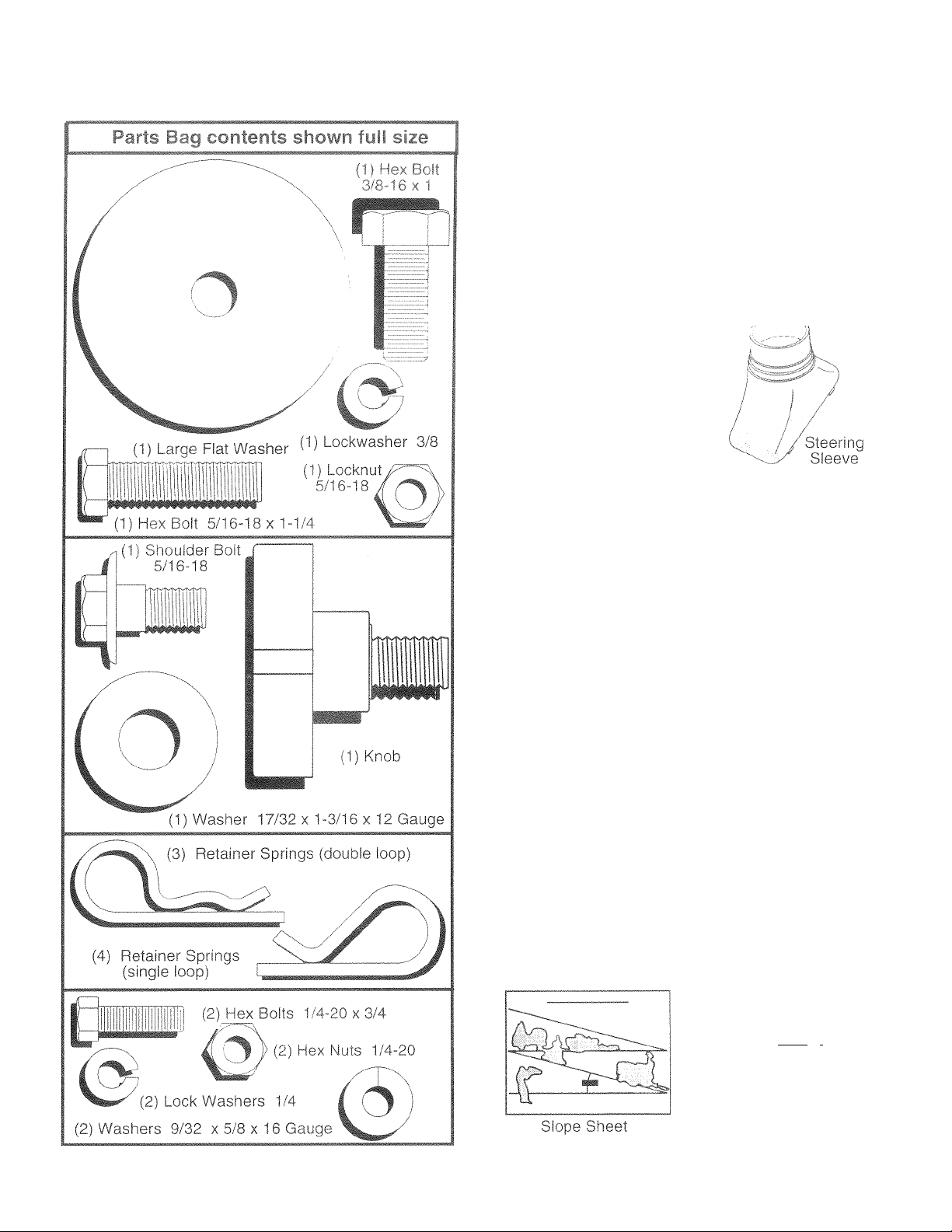
CONTENTS OF HARDWARE PACK
Steering Wheel
f in carton
Manual
Parts b ' ntenis not shown ful! size
(2) Shoulder
Bolts
(2) Center-
lock Nuts
Steering
Wheel
Insert
W (2) Washers 3/8
i i X 7/8 X 14 Gauge
Steering
Extension
Shaft
(2) Front Link Assemblies
Steering Wheel
Parts Bag
(2) Gauge
Wheels
i i! i i I j
Adapter
(2) Keys
Page 6
YOU!Ì t - / ' ' 1 i
nsure S3.f'
To e
the ccorrect toe
TOi
OLS R
A soiC)ket wreO'
I " lie I < • i nr 1^ J cti ru f icio ; \u ri
and proper operation of your tractor all part;
s as necessary to insure proper tightness.
EQUIRED FOR ASSEMBLY
h set will make assembly easier. Standard
wrench sizes c
(f) SA'" So( I ( . I it Utility knife
(2) 7/16" wrenches Tire pressure gauge
(2) 1/2" wrenches Pliers
(1} 9/16" wrench
When right or left hand is mentioned in this manual, it
means v/hen you are in the operating position (seated
behind the steering wheel).
TO REMOVE TRACTOR FROM CARTON
UNPACK CARTON
• Remove all accessible loose parts and parts cartons
from carton (See page 5).
• Cut, from top to bottom, along lines on all four corners
of carton, and lay panels flat.
• Check for any additional loose parts or cartons and
remove.
copi,on ji musr cm oieltun-ccc ihlco ^ . hi| ,cnti m. <c
! and hardware you assemble must be tightened securely.
BEFORE ROLLING TRACTOR OFF SKID
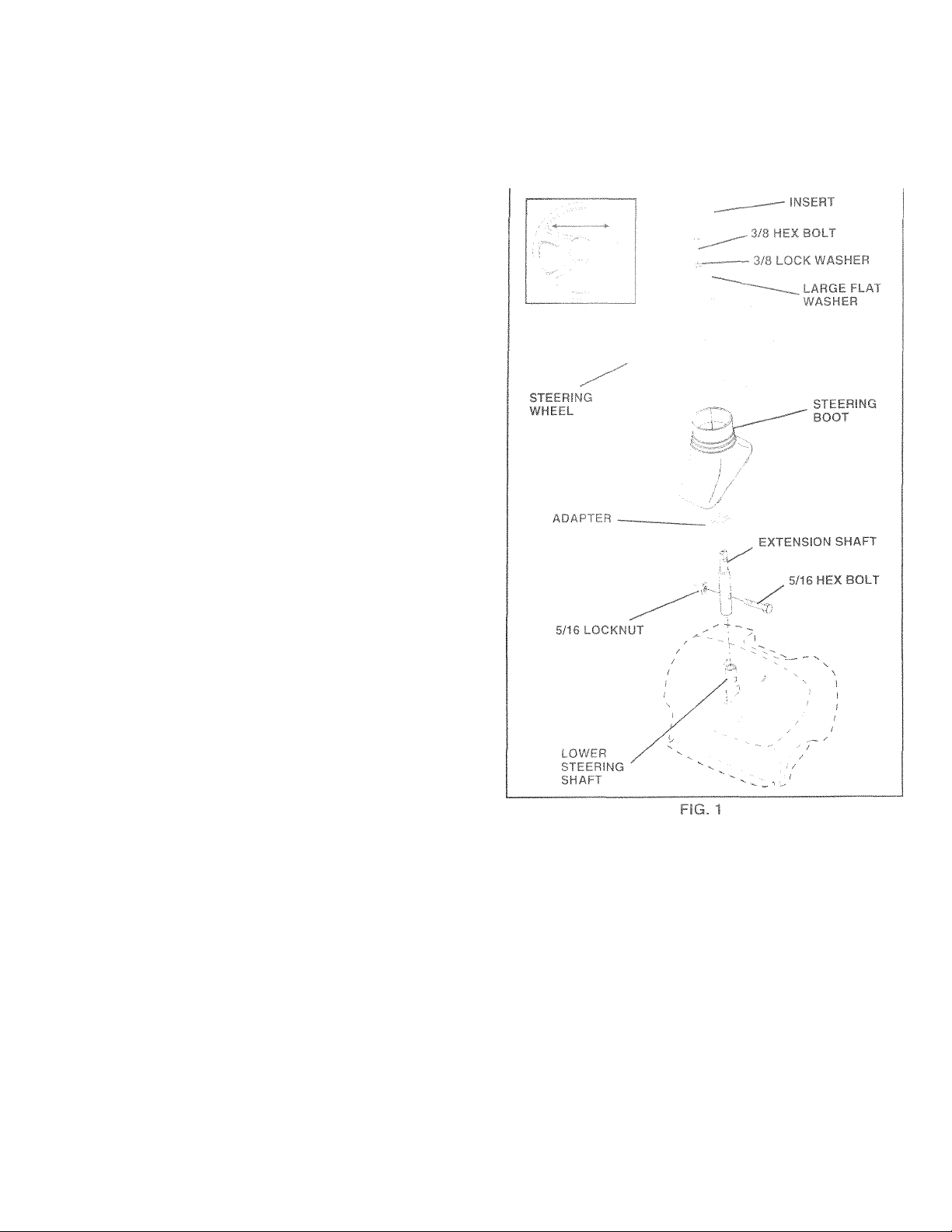
ATTACH STEERING WHEEL (See Fig. 1)
ASSEMBLE EXTENSION SHAFT AND BOOT
• Slide extension shaft onto lower steering shaft. Align
mounting holes in extension and lower shafts and
install 5/16 hex bolt and locknut. Tighten securely,
IMPORTANT: TIGHTEN BOLT AND NUT SECURELY TO
18-22 FT, LBS TORQUE,
• Place tabs of steering boot over tab slots in dash and
push down to secure.
INSTALL STEERING WHEEL
• Position front wheels of the tractor so they are pointing
straight forward.
• Slide steering wheel adapteronto steering shaft exten
sion.
• Position steering wheel and sleeve assembly so cross
bars are horizontal (left to right) and slide onto adapter.
• Assemble large fiat washer, 3/8 lock washer, 3/8 hex
bolt and tighten securely.
• Snap steering wheel insert into center of steering
wheel.
• Remove protective plastic from tractor hood and grill.
IMPORTANT: CHECK FOR AND REMOVE ANY STAPLES
IN SKIDTHATMAY PUNCTURE TIRES WHERE TRACTOR
IS TO ROLL OFF SKID.
TO ROLL TRACrOR OFF SKID (See Opera
tion section for location and function of con
trols)
• Press lift lever plunger and raise attachment lift leverto
its highest position.
• Release parking brake by depressing dutch/brake
pedal.
• Place freewheel control m freewheeling position to
disengage transmission (See 'TO TRANSPORT” in
the Operation section of this manual).
• Roll tractor backwards off skid.
• Remove banding holding discharge guard up against
tractor.
Page 7

M j-hj -^1 S - f Up itifi'iB/lC:'rOR
CONNECT BATTERY (See Fig. 2)
CAUTION: Do not short battery termi-
i ‘ i .r t ' , ■ ' I i
A
b. ,ic! Mi. j , eic.
Positive terminal must be connected
first to prevent sparking from acciden
tal grounding.
• Lift hood to raised position.
• Open terminal access doors, remove terminal protec
tive caps and discard.
« if this battery is put into service after month and year
indicated on label (label located between terminals)
charge battery for minimum of one hour at 6-10 amps.
• First connect RED battery cable to positive (+) battery
terminal with hex bolt, flat washer, lock washer and hex
nut as shown. Tighten securely.
• Connect BLACK grounding cable to negative (-) bat
tery terminal with remaining hex bolt, flat washer, lock
washer and hex nut.
• Close terminal access doors.
Use terminal access doors for:
• Inspection for secure connections (to tighten hard
ware).
• Inspection for corrosion.
• Testing battery.
• Jumping (if required).
• Periodic charging.
I fir.) -h I i r t. h
* •
Tighten securely.
rrdCTM f [ A‘f Fhf f,
¿ujust 'j- I IH..IO' - iyti(‘=-miiu m '-1 ■ ImiOl.
• K0rnov6 c3rdD03rci packiriQ on sG3t psn.
' d| (f V n ¡>..1'rina '-m <Ne r.hmildnr Iron
' m L - ul djnsirri'aii Oiob ano ilad A/mppi loosclv
r„/(,i noi iKiiimri.
® i t If '<1 [ POi { ~ U i F i /
• n seat.
• hed which
I the way
• lOLit moving its adjusted position.
‘ tighten adjustment knob securely.
FIG. 3
Page 8

A eoci
Imm !
ilE
H 1^ T*°l
The tires on your t
shipping purpose:s. Correct tire pressure is important for
PRESSURE
sc ii w( ii 0./'- .iirt'au 0 ui cii' i.K'Mrvioi
best cutting perroi mailU::.:
i p( 1 1 , 1 r 1
SPECIFICATIONS” on page 3 of this manual.
CHECK Itf'/Ti :,E SYSTEM
ATier you learn now to operate your iracior. cnecK to see
that the brake is
BRAKE" in the Service anci Adjustments section of this
sressure to PSI shown in “PRODUCT
properly adjusted. See "lO ADJUST
manual.
CHEi
BEI-ORE
.j..
^CTO
THlEBESTPERFORMANi.Az'ANUS/
THIS QU,ELITY PRCEIH..JC T.
PLtEASE HE F(AL
/
All as
No if
/
Battei
1 hOLJ
Seat I
/
/
All tirr
the tires were ov erinfiate;d at the
Re 11
/
in rn
pnp
( he I < mower an
/
prope
Cue ' 1< wiring, Sc
/
and wires are pn
t-ittOli
/
dii'/i ‘
WHILE LEARNING HOWTO USE YOUR TRACTOR. PA Y
EXTRA ATTENTION TO THE FOLLOWING IMPORTANT
ITEMS:
/ Engine oil is at proper level.
/ Fue! tank is filled with fresh, clean, regular unleaded
gasoline.
/ Become familiar with all controls - their location and
function. Operate them before you start the engine.
/ Be sure brake system is in safe operating condition.
/ It is important to purge the transmission before operat
ing your tractor for the first time. Follow proper starting
andtransmission ourqing instructions (See'TO START
ENCilNE^' and "PURGE TRANSMISSION” in the Op
eration section of this manual).
YOU OP.ERA TEAND £ENJOY YOUFE NEW
fV M./W !y//C
semoiv "-m
maininq kuC
-y jC; arc CP''
r oi) o aa'jCi:
;S ai"G ore Of
re mower c
o-rear for i oest cut
riy inflated for ieve^Tig).
E propri
conefort
oriy inlin.ted, iF( Dses,
leek IS i
' n Hi
!\/ afoi c '
e onvinc] O’cactor, be
puHeys.and insr
re that aII cenne
jpetiy c lamped.
OICL/i >r
JC/ /per '
THA T YO U RECEIVE
E TIE) FA C TION FROM
1 f'^IA/lkl
> have b■een completed
red and mum
' i!,
ting res uk' (irr must be
telts. Be
? sure fr 1 e'Kneel rontif)| is in
‘-‘V I !
on.
rely.
factory).
1 r ! g ,idi to side/
II Ihf / r.ir muted
1, libfeittf ['ers.
(IK ns am [ill secure
8
Page 9
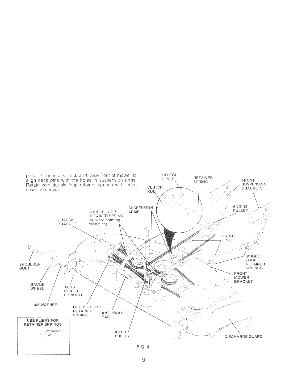
.L MOWi
Figs
• cut and remove
and 5)
factor is on
raised with
iki
Swing anti
c//ay ba
3ce a
it 'hi
fhrr
curing anth
!oit oido oi
E BELT (See
lower suspension
.cn'rol. Engage park-
i/ay bar and belts,
sower deck.
• Slide mower under tractor with discharge guard to right
side of tractor.
iMPORTANT; CHECK BELT FOR PROF'ER ROUTING ¡N
ALL MOWER PULLEY GROOVES, INSTALL BELT INTO
ENGINE PULLEY GROOVE,
» Install one front linK in top hole of the L.H. front mower
bracket and L.H, front suspension bracket. Retain with
two single loop retainer springs as shown,
• Install second front link in R.H. front suspension bracket
and retain with single loop retainer spring as shown.
• Slide right side of mower back and install link in top hole
of R.H. front m,ower bracket. Retain with single loop
retainer spring as shown,
• Turn height adjustment knob counterclockwise until it
stops.
» Lower miower linkage with attachment iift control.
Place the suspension arms on outward pointing deck
Connect anti-sway bar to chassis bracket under left
footrest and retain with double loop retainer spring.
Install clutch rod in clutch lever. Secure with retainer
spring.
Turn height clockwise to remove
slack f.rom n
Raise deck i
■as shown
СНЕС
MOWER LEVELNESS
Foidc.. I 1 iiiv I cuiis nv'Vi.r iiouki po piopc ily leveled.
Stt ¡0 L.L /l.l_ MOWEn HuUbIMG m [he Cervice and
Adjustmients section of this manual.
ClltfO
БГ* 0
See the figures that are s
dm I- I "f I I I If
A *Ju h < ( I i>
rn Ю
■ive
lanu
SmON OF ALL
ilacing motion, mower
5 in the Service and
Gerify that the belts are
к UP ti ( I n 1 V
culder
ighten
Page 10

OPERATiON
These symbols msiy appear on your tractor or in literature supplied with the product. Learn and understand their meaning.
I
BATTERY
CAUTION OR
WARNING
STOPI
REVERSE FORWARD FWST
SLOW
I
ENGINE ON ENGINE OFF OIL PRESSURE CLUTCH LIGHTS ON LIGHTS OFF
fi
FUEL CHOKE
R N H
MOWER HEIGHT DIFFERENTIAL PARKING BRAKE UNLOCKED
LOCK LOCKED
©
(®)|I
Ik
REVERSE NEUTRAL HIGH LOW
I
MOWER LIFT
DANGER, KEEP HANDS AND FEET AWAY
ATTACHMENT
CLUTCH ENGAGED
PARKING BRAKE
*
ATTACHMENT
CLUTCH DISENGAGED
HYDROSTATIC FREE WHEEL
(Hydro Models only)
10
Page 11
KNOW t'K
-r'l; * Aiiu ' ^ ikiif
Compare? the if fust rations with yourtractorto familiarize yourself with th
liii" nr I jal y I ! 1 ui( f r'ri
FORE OPERATINi
jtions of various control
lACTOR
jnts. Save
Our tractors conform to the safety standards of the American National Standards Institute.
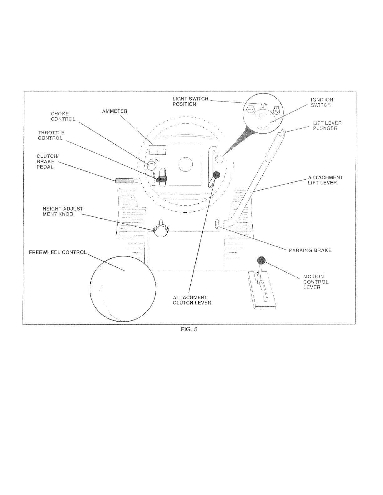
ATTACHMENT CLUTCH LEVER: Used to engage the
mower blades, or other attachments mounted to your
tractor.
LIGHT SWITCH: Turns the headlights on and off.
AMMETER - Indicates charging (+) or discharging (-) of
battery.
CHOKE CONTROL - Used when starting a cold engine.
THROTTLE CONTROL - Used to control engine speed.
CLUTCH/BRAKE PEDAL - Used for declutching and
braking the tractor and starting the engine,
PARKING BRAKE - Locks clutch/brake pedal into the
brake position.
MOTION CONTROL LEVER - Selects the speed and
direction of tractor,
ATTACHMENT LIFT LEVER - Used to raise and lower the
mower deck or other attachments mounted to your tractor.
LIFT LEVER PLUNGER - Used to release attachment lift
lever when changing its position,
IGNITION SWITCH - Used for starting and stopping the
engine.
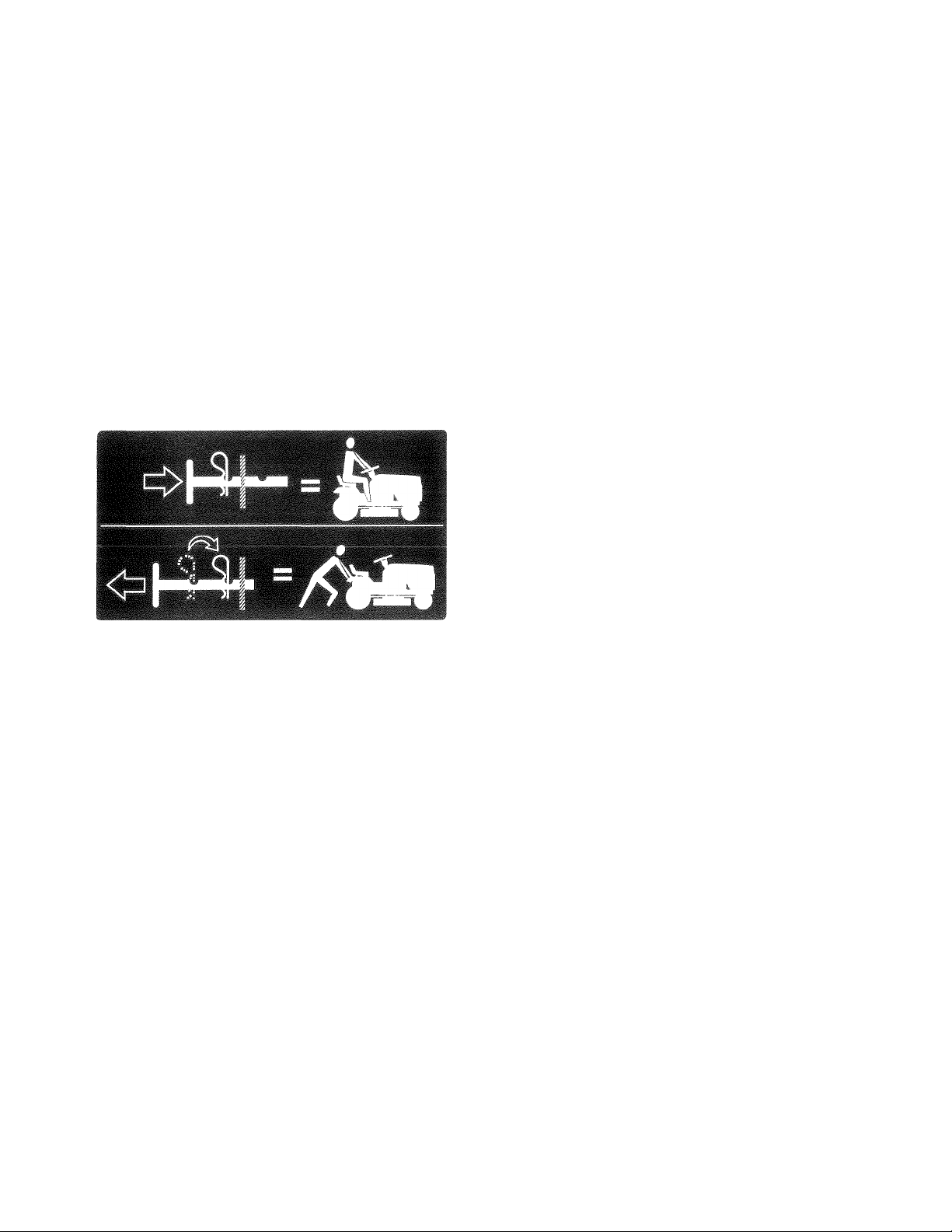
FREEWHEEL CONTROL - Disengages transmission for
pushing or slowly towing the tractor with the engine off,
HEIGHT ADJUSTMENT KNOB - Used to adjustthe mower
cutting height.
11
Page 12

ie operai
suit in Sí
îur tracte
lt6t¥ ÏTI3S
iny irdcior Cdïl resi
/e damage. Always
perform ir
'er the spe
nv adju
it in foreign objects
wear safety glass«
Affi ^ il •• i
tandard safety qla.
ye sriie
recomr
while operating
d a wide vision
_J
HOW ■ < 4- ' Hlr I'
TO lT i i '•Ohllti ^ H ■ f e ' 'fj. c|
hour cat ic'S ( (J''u* Ml. HIM i .r j (est nc e censini;
swilch \/'hi-n -fiC's iiihMTK) iv i'lPinpi hv 'tie
opcrcioiu itM' I ' . M '] ! u.i oMiiiiii ih' par'iing
brake will hui . . ' f f. 'jnu
Depia s.luu i> l l.< irn j nl' f P/M~ ’ f-i'
ana noici.
• Place parking brake lever in “ENGAGE:D”j:)Osition and
release pressure from clutch/brake pedal. Pedal should
remain in “BRAKE” position. Make sure parking brake
will hold tractor secure.
A I TAi HIUkrt r CLUTCH LEVER
FNG/,GEL POSITION
THROTTLE
CONTRO!.
CLUTCH/
BRAKE
PEDAL
“DRIVE”POSITION
.
FIG. 6
“DISENGAGED”
POSITION
PARKING
BRAKE
“ENGAGED”
POSITION
GEARSHIFT LEVER
/
\ DISENGAGED”
.'OSITION
'“'I; Always stop tractor coiri“ |
s described above, before ieavoperator's positioii; to empty
tcher, etc»
TO?- i row ■ r^Thr," of TDeeFig. 6)
Aiwa/,. , M M u ig ii i1 ili ih o ill
® Operating engine at less than full throttle reduces the
battery charging rate.
• Full throttle offers the best bagging and mower perfor
mance.
TO USE CHOKE CONTROL (See Fig. 6)
Use choke control whenever you are starting a cold engine.
Do not use to start a warm engine.
® To engage choke control, pull knob out. Slowly push
knob in to disengage.
TO MOVE r IRWaRO T f^D BACKWARD (See
Fig. 6)
The direction and speed of movement is controlled by the
motion control lever.
• Start tractor with motion control lever in neutral (N)
position.
• Release parking brake and clutch/brake pedal.
• Slowly move motion control lever to desired position.
STOPPING (See Fig. 6j
MOWER BLADES ■
• Move attachment clutch lever to “DISENGAGED” po
sition.
GROUND DRIVE -
• Depress clutch/brake pedal into full “BRAKE” position.
• Move motion control lever to neutral (N) position.
IMPORTANT: THE MOTION CONTROL LEVER DOES
NOT RETURN TO NEUTRAL (N) POSITION WHEN THE
CLUTCH/BRAKE PEDAL IS DEPRESSED,
ENGINE -
• Move throttle control to slow i -^) position.
NOTE: Failure to move throttle control to slow c^)
position and allowing engine to idle before stopping may
cause engine to “backfire”
• Turn ignition key to “OFT” position and remove key.
Always remove key when leaving tractor to prevent
unauthorized use.
• Never use choke to stop engine.
NOTE: Under certain conditions when tractor is standing
idle with the engine running, hot engine exhaust gases may
cause “browning” of grass. To eliminate this possibility,
always stop engine when stopping tractor on grass areas.
TO ADJUST MOWER CUTTING HEIGHT (See
Fig. 6)
The cutting height is controlled by turning the height
adjustment knob in desired direction.
• Turn knob clockwise (“ t) to raise cutting height.
• Turn knob counterclockwise (AT) to lower cutting
height.
The cutting height range is approximately 1-1/2" to 4". The
heights are measured from the ground to the blade tip with
the engine not running. These heights are approximate
and may vary depending upon soil conditions, height of
grass and types of grass being mowed.
• The average lawn should be cut to approximately 2-
1/2 inches during the cool season and to over 3 inches
during hot months. For healthier and better looking
lawns, mow often and after moderate growth.
• For best cutting performance, grass over 6 inches m
height should be mowed twice. Make the first cut
relatively high; the second to desired height.
12
Page 13

MT
I f-ayc5fc i<P£ FSij. %
f-tj\\\ j- ,J J vh I A/'tll liruU I I,n |?,|if>'i i.M !■
• Adjust mower to desired cutting height (See ‘TO AD
JUST MOWER CUTTING HEilGUr” in the Operation
section of this manual).
® With mower in desired height of cut position, gauge
wheels shouid be assembled so they are slightly off the
ground, install gauge wheel in appropriate hole with
shoulder bolt, 3/8 washer, and 3/8-16 locknut and
tighten securely.
• Repeat for opposite side installing gauge wheel in
same adjustment hole.
GUAGE
WHEEL
MOUNTING
BRACKET"
3/8-16-^
LOCKNUT
3/8 WASHER
GAUGE WHEEL
TA
SHOULDER BOLT
/
FIG. 7
TO OPERATE MOWER (See Fig. 8)
Your tractor is equipped with an operator presence sensing
switch. Any attempt by the operator to leave the seat with
the engine running and the attachment clutch engaged will
shut off the engine.
• Select desired height of cut.
• Lower mower with attachment lift control.
• Start mower blades by engaging attachment clutch
control.
• TO STOP MOWER BLADES - disengage attachment
clutch control.
ATTACHMENl
"ENGAGED'
CLUTCH LEVE
USED
riON
"LUW ■
POSITION
ATT.ACHIV1ENT
LIFT LEVER
"HIGH"
POSITION
FIG. 8
TO orí HILLY
A
l4 '
Ink
Avoid
If slowing i‘ nm r r / h J till k- Í
G not;
n -lc»Mr '
/e acros
eirawwocL
I' ’ I Í j ' Í
slowei oca i ell
• If stopping IS absolutely necessary, push clutch/brake
pedal quickly to brake position and engage parking
brake.
• Move motion control lever to neutral (N) position.
IMPORTANT; THE MOTION CONTROL LEVER DOES
NOT RETURN TO NEUTRAL (N) POSITION WHEN THE
CLUTCH/BRAKE PEDAL IS DEPRESSED.
• To restart movement, slowly release parking brake and
clutch/brake pedal.
• Slowly move motion control lever to slowest setting.
• Make all turns slowly.
I ir. ft'-U di
; greater 1
ive up ore
than IS'"a
■s any sic
cnfopri Kr "Jr^rci etwrti
mpptd'J uL
iangtng s|
i( d )i 1
nd d( not
' down
CAUTION: Do not operate the mower
without either the entire grass catcher,
on mowers so equipped, or the dis
charge guard in place.
13
Page 14
то TRANSPORT (See Figs. 9 and 5)
When pushing or towing your tractor, be sure to disengage
transmission by placing freewheel control in freewheeling
position. Free wheel control is located at the rear drawbar
nf traritii-
• Raise attachment lift to highest position with attach
ment lift control,
' Pull lipovdii ( I cm hoi I mh о i , no ■ * in mo uo i bv
inbeiiiiig ii c.iof-f |j I I I If, о m' ti fo u тлоп'
roa,
I'C uui I |Чт>,тго,/| , in ro iMoio ,haii ICO i i'/,P4
" 1 о reel o. 1 i mno ^, n lO/er* < Lcn/e r row dutc
mil о ,.i I' R "p
voui ii ■( : I ii I
and i i I ( 111 ' ' I I I
hood lo I . t ,i (П I ( ' ' ii
damaeje when transporting
liter, be sure hood is dosed
o oroj u t( meai'S of l,/>nn
P... i
IMPORTANT: WHE
BELOW 32 F(0”C),l
GASOLINE TO HEL
STARTING.
WARNING: Experi
fuels (called gasohe
'll 111 > ^ 1 im III'
acids durino sioragi
S m , ' m
p,i,0' I I
age of 30 days or l(
er fiir'e f n • II
eti'p / 11
[iCi I h I I I
t.ainurc-. I I
On I, I ill (
CAUTION: Fill to bottom of gas tank
; :t W m , ( .f [(/. , ii Wipe c If any
.1 i' 'I' <1 li'- Í c it , tere, rpill Oi
A
'■Cl- 1 le 'if r ‘.fi I ¡i' П "lame.
OPERATING
FRESH, CL
MSURE GO(
torage.
id be em;
in the c|£IS tank, start the
a lines ar
>on, See
Ì, N S' V er use engine or
ne luel ta:Пк or clerrnanent
EMPERATURES
VINTER GRADE
OLD WEATHER
alcohol blended
r m.ethanol) can
and formation of
, e Fwl
i Oiigitie
hi
afore stor-
j (
mretor are
je Instruc-
Storac
FIG. 9
BEFORE STARTING THE ENGINE
CHECK ENGINE OIL LEVEL (See Fig. 16)
• The engine in yourtractor has been shipped, from the
factory,' already filled with summer weight oil.
• Check engine oil with tractor on level ground.
• Unthread and remove oil fill cap/dipstick; wipe oil off.
Reinsert the dipstick into the tube and rest oil fill cap on
the tube. Do not thread the cap onto the tube. Remove
and read oil level. If necessary, add oil until “FULL”
mark on dipstick is reached. Do not overfill.
• For cold weather operation you should change oil for
easier starting (See “OIL VISCOSITY CHART” in the
Customer Responsibilities section of this manual).
• To change engine oii, see the Customer Responsibili
ties section in this manual.
ADD GASOLINE
• Fill fuel tank. Use fresh, clean, regular unleaded
gasoline with a minimum of 87 octane. (Use of leaded
gasoline will increase carbon and lead oxide deposits
and reduce valve life). Do not mix oil
Purchase fuel in quantities that can be used within 30
days to assure fuel freshness.
with gasoline.
TU . ] I Mí {ML
When I III inr> I 1 m
has I un on I he ' I
fuel froi n [' ' I I 1 to II I t
• He sill*., iccotteci c
/С
Pw Fig. 6)
first time or if the engine
a cranking time to move
gine.
... .in the transmission en
gaged position.
• Sit on seat in operating position, depress clutch/brake
pedal and set parking brake.
• Place motion control lever in neutral (N) position.
• Move attachment dutch to “DISENGAGED” position.
• Move throttle control to fast («%) position
• Pull choke controi out for a cold engine start attempt.
For a warm engine start attempt the choke control may
not be needed.
Note: EBefore starting, read the warm and cold starting
procedures below,
» Insert key into ignition and turn key clockv/ise to “START”
position and release key as soon as engine starts. Do
run starter continuously for more than fifteen sec
not
onds per minute. If the engine does not start after
several attempts, push choke control in, wait a few
minutes and try again. If engine still does not start, pull
the choke control out and retry.
WARM WEATHER STARTING (50° F and above)
• When engine starts, slowly push choke control in until
the engine begins to run smoothly. If the engine starts
to run roughly, puli the choke control out slightly for a
few seconds and then continue to push the control in
slowly,
• The attachments and ground drive can now be used. If
the engine does not accept the load, restart the engine
and allow it to warm up for one minute using the choke
as described above,
COLD WEATHER STARTING (50° F and below)
• When engine starts, slowly push choke control in until
the engine begins to run smoothly. Continue to push
the choke control in small steps allowing the engine to
accept small changes in speed and load, until the
choke control is fully in. If the engine starts to run
roughly, pull the choke control out slightly for a few
seconds and then continue to push the control in
slowly. This may require an engine warm-up period
from several seconds to several minutes, depending
14
on the temperature.
Page 15

RANSMISSION WARM UP
the unit in cold weatt
Jon should
r warmed up as follow
le tractor is on level gr 'ound.
motion control lever ir
ie parking brake and le
• Allow one minute for transmission to warm up.
This can be done during the engine warm up
period.
• The attachments can be used during the engine warm
up period after the transmission has been warmed up
and may require the choke control be pulled out sligntly,
NOTE: If at a high altitude (above 3000 feet) or in coid
temperatures (below 32 F) the carburetor fuel mixture may
need to be adjusted for best engine performance. See "TO
ADJUST CAREJURETOR” in the Service and Adjustments
1er, the transmis-
i neutral.
ihr 1 Íilr li/oi' ke
section of this manual.
PURGE TRANSMISSION
CAUTION. Never engage or dicengage
trenwheei ¡ever while the engine is run
A
To ensure proper operation and performance, it is recom
mended that the transmission be purged before operating
tractor for the first time. This procedure will remove any
trapped air inside the transmission which may have devel
oped during shipping of your tractor.
IMPORTANT: SHOULD YOUR TRANSMISSION REQUIRE
REMOVAL FOR SERVICE OR REPLACEMENT, IT
SHOULD BE PURGED AFTER R E i N ST ALL ATI ON
BEFORE OPERATING THE TRACTOR.
• Place tractor safely on level surface with engine off and
parking brake set,
• Disengage transmission by placing freewheel control
in freewheeiing position (See 'Tb TRANSPORT” in
this section of manual).
• Sitting in the tractor seat, start engine. Afterthe engine
is running, move throttle control to slow {•0A) position.
With motion control lever in neutral (N) position, slowly
disengage clutch/brake pedal.
• Move motion control lever to full forward position and
hold for five (5) seconds. Move lever to full reverse
position and hold for five (5) seconds. Repeat this
procedure three (3) times.
NOTE: During this procedure there will be no movement of
drive wheels. The airis being removed from hydraulic drive
system.
• Move motion control ieverto neutral (N) position. Shut
off engine and set parking brake.
• Engage transmission by placing freewheel control in
driving position (See 'TO TRANSPORT” in this section
of manual),
• Sitting in the tractor seat, start engine. Afterthe engine
is running, move throttle control to half (1/2) speed.
With motion control lever in neutral (N) position, slowly
disengage clutch/brake pedal.
ning.
Slowly move motion c(
tractor moveos apiproxirri
motion control lever tc ) reverse pc
tractor moves approxir
motion control Ieverto it le neutral (N ) position. Repeat
this procedure with the ITiOtlOn СОГТtrol lever three (3)
Your tractor IS now purged and now ready tor normal
operation.
WOVr:'-
peiii
the ;
Ih
m i
t
tl I 11 i I • r>n cut. Have the cut area, to the right of the
ti, I 01 I IS Will result in a more even distribution of
clii 1 I 'I "ud more uniform cutting.
\ ig large areas, start by turning to the right
S( J ' ippings wiii discharge away from shrubs,
fcuccs oiiveways, etc. After one or two rounds, mow
in I he opposite direction making left hand turns until
finished (t,ee Fig. 10).
If grass IS extrerneiy tall, it should be mowed twice to
reduce lead and possible fire hazard from dried clip
pings. Make first cut reiaiively high; the second to the
desired neight.
Do no» mow grass when it is wet. Wet grass will plug
mowca and leave undesirable clumps. Allow grass to
dry before mowing.
Always operate engine at full throttle when mowing to
assure better mowing performance and proper dis
charge of material. Regulate ground speed by select
DC
to tractor,
V -lu /'djustments section of this manual.
d side of mower should be used for trim-
t clippings are discharged onto the area
Dntro! iever
ately five (5'
nateiy five (
9 used when the mower housing is
dCDeriv leveled for best mowinq
"O LEVEL. MOWER HOUSING” in
kv/v,,io r.ii.-i ih-
1 feet, slowly move
S'Sition. After the
me, n-V)t 1 mr
ing a low enough gear to give the mower cutting
performance as weli as the quality of cut desired.
When operating attachments, select a ground speed
that will suit the terrain and give best performance of
the attachment being used.
15
Page 16

CUSTOMER RESPONSIBILITSES
3 - It equipped with
4 - Replace blades
y 50 hours,
g in sandy soil
GENERAL HLCi.mm
The warranty on this tractor does not cover items that have
been subjected to operator abuse or neqliqr nee. To
receive full value from the warranty, operator,, ., .aintain
tractor as instructed in this manual.
Some adjustments will need to be made periodically to
properly maintain your tractor.
All adjustments in the Service and Adjustments section of
this manual should be checked at least once each season.
• Once a year you should replace the spark plug, clean
or replace air filter, and check blades and belts for
wear. A new spark plug and clean air filter assure
proper air-fuel mixture and help your engine run better
and last longer.
BEFORE LAi fd t toL
• Check engine oil level.
• Check brake operation.
• Check tire pressure.
• Check for loose fasteners.
-lbs. m£ixirnum.
nON CHART
(DsPINDLE ZERK—
(D FRONT WHEEL
BEARING ZERK
©ATTACHMENT
CLUTCH
PIVOT(S) C
©SAE 30 OR 10W30 MOTOR OIL
©GENERAL PURPOSE GREASE
©REFER TO CUSTOMER RESPONSIBILITIES “ENGINE” SECTION
IMPORTANT: DO NOT OIL OR GREASE THE PIVOT POINTS
WHICH HAVE SPECIAL NYLON BEARINGS. VISCOUS LUBRI
CANTS WILL ATTRACT DUST AND DIRT THAT WILL SHORTEN
THE LIFE OF THE SELF-LUBRICATING BEARINGS.
FEEL THEY MUST BE LUBRICATED, USE ONLY A DRY, POW
DERED GRAPHITE TYPE LUBRICANT SPARINGLY.
-----
------) ____________
p—SPINDLE ZERK(2)
FRONT WHEEL©
BEARING ZERK
GEARSHIFT ©
PIVOTS
16
ENGINE @
IF YOU
Page 17

OJ:
I I llfl
U
11
ITiCC
■RACTOF
Iways obsen. ules when performing any mair
BRAKE OPERATION
It tractor requires mor
at high speed in hiahe:
(See “TO ADJUST E
ments section of this i
® Maintain omoer air pressure in all tires (See "PROD^^
UCT SPECIFiCATIONS” on page 3 of this manual),
» Keep tires tree of gasoline, oil, or insect control chemi
cals which can harm rubber.
• Avoid stumps, stones, deep ruts, sharp objects and
other hazards that may cause tire damage.
NOTE: To seal tire punctures and prevent flat tires due to
slow leaks, tire sealant may be purchased from your local
parts dealer. Tire sealant also prevents tire dry rot and
corrosion.
BLADE CARE
For best results mower blades must be kept sharp. Re
place bent or damaged blades.
BLADE CARE
For best results mower blades must be kept sharp. Re
place bent or damaged blades,
m &u iO; icei iiuoui m liSianor
jear, tnen brake must
>^1- In heivKi i|ii Adju^
tnuau.
J|i 'seed
TO SHARPEN BLADE (See Fig. 12)
Care should be taken to keep: the blade balanced. An
.1(1, Ik Ih n i Wf- ' Pt null ai, - (Pii
tual dam.a ye to mower and engine.
• The blade can be sharpened with
wheel. Do not attempt to sharper
• To check blade balance, you will need a 5./8" diameter
steel boil. pin. ora cone balancer. iTA'ien using a cone
balancer, follow the mstruciions supplied with bal
anced,
• n ^ 'll , n -1 I >1 I -el bolt
or pm and hold trie bolt or pm oamllel with the ground.
If blade IS balanced, i! should remain in a horizontal
; '{,11,1,- I i[,( I [ '( 11 I ' ufc D, iward,
1 I I- I I / m I I ' n m IIK . u lb I im • ed
NOTE: Do not use a nail for balancing blade. The lobes of
the center hole may appear to be centered, but are not.
CENTER HOLE
5./8" BOLT
OR PIN -—
"Oil' I inm, ig
on the mower.
BLADE
BLADE REMOVAL (See Fig. 11)
.• Raise mower to highest position to allow access to
blades.
• Remove hex bolt, lock washer and fiat washer securing
blade.
• Install new or resharpened blade with trailing edge up
towards deck as shown,
• Reassemble hex bolt, lock washer and flat washer in
exact order as shown.
• Tighten bolt securely (30-35 Ft. Lbs. torque).
IMPORTANT: BLADE BOLT ISGRADE 8 HEATTREATED,
NOTE: We do not recommend sharpening blade - but if you
do, be sure the blade is balanced.
.it:; MANDREL
' ASSEMBLY
BLADE
á
TRAILING EDGE
HEX BOLT
(GRADE 8)*
FIG. 12
BATTERY
Your tractor has a battery charging system which is suffi
cient for normal use. Flowever, periodic charging of the
battery with an automotive charger will extend its life.
• Keep battery and terminals clean,
• Keep battery bolts tight.
• Keep small vent holes open.
• Recharge at 6-10 amperes for 1 hour.
TO CLEAN BATTERY AND TERMINALS
Corrosion and dirt on the battery and terminals can cause
the battery to “leak” power.
• Remove terminal guard.
• Disconnect BLACK battery cable first then RED bat
tery cable and remove battery from tractor.
• Rinse the battery with plain water and dry,
• Clean terminals and battery cable ends with wire brush
until bright.
• Coat terminals with grease or petroleum jelly.
• Reinstall battery (See “CONNECT BATTERY” in the
Assembly section of this manual).
*A GRADE 8 HEAT TREATED BOLT CAN BE
IDENTIFIED BY SIX LINES ON THE BOLT HEAD.
FIG. 11
17
Page 18

V-BELTS
Check V^belts for deterioration and wear after 100 hours of
operation and replace if necessary,. The belts are not
adjustabiw Ffeplace belts if they begin to slip from ¥,'ear.
' iNSAXLE COOLING
The fan and cooling fins of transmission should be kept
clean to assure proper cooling.
Do not attempt to clean fan or transmission while engine is
running or while the transmission is hot,
• Inspect cooling tan to be sure fan blades are intact and
clean.
• Inspect cooling fins for dirt, grass clippings and other
materials. To prevent damage to seals, do not use
compressed air or high pressure sprayer to clean
cooling fins.
TRANSAXLE PUMP FLUID
The transaxle was sealed at the factory and fluid maintenance is not required for the life of the transaxle. Should the
transaxle ever leak or require servicing, contact your near
est authorized service center/department.
ENGINE
TC CHANGE ENGINE OIL (See Fig. 13)
Determine temperature range expected before oil change.
All oil must meet API service classification SF, SG or SH.
Be sure tractor is (3n levei surface.
Oil will drain more freely when warm.
careful not to allow dirt
ging oil.
/. replace oil drain plug
' N I I 1 ' M [i|i fli 1 (X ‘ul Pour
H ly 'll' 1 I 1 iioxin -do ( ip city see
Ml (' r L M' 1 >N k )| I I ■ 01 pm of this
manual.
Use gauge on oil fill cap/dipstick tor checkin i wel. Be
sure dipstick cap is tightened secuiely toi accurate
reading. Keep oil at “FULL” line on dipstid
LUBRICATION
Only use high quality detergent oil rated with API service
classification SF, SG or SH. Select the oil’s SAE viscosity
grade according to your expected operating temperature.
SAE VISCOSITY GRADES
TLV.'ERATURE RAK^
■ 20
NOTE: Although multi-viscosity oils (5W30, 10W30 etc.)
improve starting in cold weather, these multi-viscosity oils
will result in increased oil consumption when used above
32°F. Check your engine oil level more frequently to avoid
possible engine damage from running low on oil.
Change the oil after the first two hours of operation and
every 50 hours thereafter or at least once a year if the
tractor is not used for 50 hours in one year.
Check the crankcase oil level before starting the engine
and after each eight (8) hours of operation. Tighten oil fill
cap/dipstick securely each time you check the oil level.
TED ! ' T-IF. M[ • r t IL C- ' NOE
18
Page 19

CUSTOMEF
air
,'t .1 i-MOIti- ' I n M f I'l M ( .h M III- iilM - ir .1,1!
f ' t U ,, . 1 f if - . . I ( I / If . ('f-i-
fuh I r V I , 1-1 > rf I ! I ! . itii > 1^*0
hi)Ui; fil 11| f If , c I, ( ■■ r v' I / ‘ lb .1 Vi/liif I t '/> . ( I .1 ; iir* i.
Service air cleaner more often under dusty conditions.
» Remove knob(s) and cover.
TO SERVICE PRE^CLEANER
Slide foam pre-cleaner off cartridge.
Wash it in liquid detergent and water.
Squeeze it dry in a dean cloth.
Saturate it in engine oil. Wrap it in dean, absorbent
cloth and squeeze to remove excess oil.
If very dirty or damaged, replace pre-cleaner.
Reinstall pre-cleaner over cartridge.
c ; t' iq
CLEAN AIR SCREEN (See Fiq. 141
Air screen must be
engine damage fror
or compressed air t
fiht I ,
ENGir
[n .Vi
na r
Mi"
and A
Reinstall cover and secure with knob(s),
TO SERVICE CARTRIDGE
Remove wing nuts and cartridge plate.
Carefully remove cartridge to prevent debris from
entering carburetor.
Clean cartridge by tapping gently on flat surface. If very
dirty or damaged, replace cartridge.
Reinstall cartridge plate, wing nuts, precleaner, cover
and secure with knob(s).
IMPORTANT: PETROLEUM SOLVENTS. SUCH AS
KEROSENE. ARE NOT TO BE USED TO CLEAN THE
CARTRIDGE. THEY MAY CAUSE DETERIORATION OF
THE CARTRIDGE. DO NOT OIL CARTRIDGE. DO NOT
USE PRESSURIZED AIR TO CLEAN OR DRY
CARTRIDGE.
I free of dirt and chaff to prevent
I I ^ i ' / 1 . a /vh 1 mdi
riove dirt and stubborn dried qum
)OLING FINS (S
Just, din or oil fror'Tl
. damage from overn
ed. Remove side pa.
t)D AND GRILL ASo
ns section of this nn
to
’ " overs
a H i e ‘TO
I li I otvice
19
Page 20

CUSTC
n r
....
¡Oil
ENGINE OIL FILTER (See Fiq. 16)
Replace the engine oil filter i
change if the tractor is usee
year.
® 'o n|f [S ( t i 'ill III 1.. .Miii'r-i^lockwise. Use a
^ 1 1 I ' , I. II i I I I'
* 'g r>i ' Uri 1 I ( 1 I yy i iDiie o,| .0 rubber gasket
I ) I I I ( ;' 1 I I 1 ' ! I 1
» In I >|i nil' ii i‘ I I I iJM inmir-n clockwise until
I'll.h r 1 t ■ 1-K I ,1'i, > r Uiii.ee, then tighten
fll. I ,rl 1 1 I
• filli liif.'i- /illi I 'iiiiw.pf fiCHANGE EENtii.t ',¡1 I I - HUw I "RFC IFICATIONS” on
pp ' . 1 ,11 I I
® Start engine and check for oil leaks. Correct any leaks
before placing engine into full operation.
' - ‘ or f ■ ^ o
)re than 100 hours in one
il). Forapproxi-
MUFFLER
Inspect and replace corroded muffler and spark arrester (if
equipped) as it could create a fire hazard and/or damage,
IN-LINE FUEL FILTER (See Fiq.
The fue
filter be
vvitn engine coon remove niter and plug fuel line
sections.
Place new fuel filter in position in fuel line with arrow
pointing towards carburetor.
Be sure there are no fuel line leaks and clamps are
properly positioned.
Immediately wipe up any spilled gasoline.
uctinq fuel flow 1
on. If fuel
jrburetor,
CLEANING
• Clean engine, battery, seat, finish, etc. of all foreign
matter.
• Keep finished surfaces and wheels free of all gasoline,
oil, etc.
• Protect painted surfaces with automotive type wax.
We do not recommend using a garden hose to clean your
tractor uniess the eiectricai system, muffler, air filter and
carburetor are covered to keep water out. Water in engine
can result in a shortened engine life.
SPARk P’ Unc
Replace spark plugs at the beginning of each mowing
season or after every 100 hours of operation, whichever
occurs first. Spark plug type and gap setting are shown in
“PRODUCT SPECIFICATIONS" on page 2 of this manual.
20
Page 21

TO BEHOVE MOWf- i. ee Fig. 18)
• Place alirchment clutch in "‘DISENGAGED” position.
• Turn height adjustment knob to lowest setting.
» Lower mower to its lowest position.
• Disconnect clutch rod from clutch lever by removing
retainer spring.
• Remove retainer spring holding anti-swaybar to chas
sis bracket and disengage anti-swaybar from bracket.
® Remove retainer springs from suspension arms at
deck and disengage arms from deck.
• Raise attachment lift to its highest position.
• Remove two retainer springs from each front link and
remove links.
CLUTCH SPRING
punev
trvvard and reme Dell from engine
• Slide :
¡MeOI , /
Ml v/r^
REMrWi
r out from under right side of tractor.
F an attachment other than the
iS TO BE MOUNTED ON THE TRACTOR,
^RONT LINKS,
TO iMStTL^ MOWER
Follow procedure described in ‘‘INSTALL MOWER AND
DRIVE BELT” in the Assembly section of this manual.
RETAINER
ENGINE
PULLEY
FRONT
SUSPENSION
BRACKET
FIG. 18
21
Page 22

3ERVK
/iCMTQ
IV!
LEVEL MOWER HOUSING
Adjust the mower wniie tractor is parkea or
driveway. Make sure tires are properly inflate
“PRODUCT SPECIFICATIONS” on page 2 of this manual),
li tires ^iieuvei V Jii'i-i o'ra o ^ lU a |i n f i lopcily dugj t
your mower.
SIDE-TO-SIDE ADJUSTMENT (See Figs. 19 and 20)
• Raise mower to its highest position.
• At the midpoint of both sides of mower, measure height
from bottom edge of mower to ground. Distance “A” on
both sides of mower shouid be the same or within 1/4"
of each other.
• If adjustmient is necessary, make adjustment on one
side of mower only.
• To raise one side of mower, tighten lift link a.djustment
nut on that side.
• To lower one side of mower, loosen lift link adjustment
nut on that side.
NOTE: Three full turns of adjustment nut will change
mower height about 1/8".
• Recheck measurements after adjusting.
{bee
approxirric -3/8"
not equal
other link.
'/n- ' k t - ' - ' , , ■ lo vet at front than
' - t Ji : Í . to,¡'VI on both front
length,.
or infiwp
adjust one lin
n nut “E” on
k to san
both fro
Hrv
To raise front ot mower, loosen nut “F” from trunnion on
both front links. Tighten nut “E" on both front links an
equal numiber of turns.
When distance "D" is TC" to 1/2" lower at front than
rear, tighten nut against trunnion on both front links.
Recheck side-to-side adiustment.
MANDREL
"b" '‘D"|
FIG. 21
BOTH FRONT LINKS MUST BE EQUAL IN LENGTH
I:
FIG. 20
FRONT-TO-BACK ADJUSTMENT (See Figs. 21 and 22)
IMPORTANT: DECK MUST BE LEVEL SIDE-TC3-SIDE. IF
THE FOLLOWING FRONT-TO-BACK ADJUSTMENT IS
NECESSARY, BE SURE TO ADJUST BOTH FRONT LINKS
EQUALLY SO
SIDE.
MOWER WILL STAY LEVEL SIDE-TO-
To obtain the best cutting results, the mower housing
should be adjusted so that the front is approximately 1 /8" to
1/2" lower than the rear when the mower is in its highest
position.
Check adjustment on right side of tractor. Measure dis
tance “D” directly in front and behind the mandrel at bottom
edge of mower housing as shown.
» Before making any necessary adjustments, check that
both front links are equal in length. Both links should be
22
/
j
.....
.
NUT "E"
NUT “F
FRONT LINKS TRUNNION
FIG. 22
TO REPLACb MOWER DRIVE BELT
MOWER DRIVE BELT REMOVAL (See Fig. 23) -
• Park tractor on a level surface. Engage parking brake.
Disengage attachment clutch control,
• Remove four screws from L.H, mandrel cover and
remove cover,
• Roll belt over the top of L.H. mandrel pulley.
• Remove belt from engine pulley.
• Remove belt from idler pulleys.
• Remove any dirt or grass clippings which may have
accumulated around mandrels and entire upper deck
surface.
Page 23

» » i
1 « 4 i
!■% Ill
rs
.ee
rotate
MOWER DHE
k6€3De
Idle
INÌ
WLATION
v1ake sure
)wn.
Fig, 23) -
; in both belt
Install new belt onto engine pulley.
Hoii Pelt into upper groove ot l,h. manarei pulley.
Carefully check belt routing making sure belt Is in the
grooves correctly and inside belt keepers.
Ih st
Ihcy
• Reinst.
AND C
all mower to t
)RIVE BELT”
rnanua
® Beasse
MOW E
L.H. MANDREL DRtVEt BELT
amble mower
tR DRIVE BEL
MOWER
/Si “[. -M,".
ractor
in the
Assembly sec
drive belt (See “TO
lis section of tl"
ivf ^ L..Ì 1 L.
SCREW
FIG. 24
1 Mf'WFi'
lion
jI
iIms
REPLACE
us manual).
SEECONDARY
IDLER ARM
SPRING
.H.
ANDREL
OVER
FIG. 23
TO REPLACE MOWER BLADE DRiVE BELT
(See Fig. 24)
Park the tractor on level surface. Engage parking brake.
• Remove mowerdrive belt (See “TO REPLACE MOWER
DRIVE BELT" in this section of this manual).
• Remove mower (See “TO REMOVE MOWER” in this
section of this manual).
• Remove four screws from R.H. mandrel cover and
remove cover.
• Carefully roll belt off R.H. mandrel pulley.
• Remove belt from center mandrel pulley, idler pulley,
and L.H. mandrel pulley.
• Remove any dirt or grass which may have accumu
lated around mandrels and entire upper deck surface.
• Check secondary idler arm and idler to see that they
rotate freely.
• Be sure spring is hooked in secondary idler arm and
sway-bar bracket.
• Install new belt in lower groove of L.H. mandrel pulley,
idler pulley, and center mandrel pulley as shown.
• Roll belt over R.H, mandrel pulley. Make sure belt is in
all grooves properly.
• Reconnect secondary clutch rod to pivot rod with
retainer spring.
• Reinstall R.H. mandrel cover.
TO ADJUST BRAKE (See Fig. 25)
Your tractor is equipped with an adjustable brake system
which is mounted on the side of the transaxle.
If tractor requires more than six (6) feet stopping distance
at high speed in highest gear, then braKe must be adjusted.
• Depress clutch/brake pedal and engage parking brake.
» Measure distance between brake operating arm and
nut "A" on brake rod.
• If distance is other than 1 -3/4“. loosen jam nut and turn
nut "A" until distance becomes 1-3/4". Retighten jam
nut against nut “A".
• Road test tractorfor proper stopping distance as stated
above. Readjust if necessary, if stopping distance is
still greater than six (6) feet in highest gear, further
maintenance is necessary. Contact your nearest au
thorized service center/department.
WITH PARKING BRAKE “ENGAGED"
/
NUT “A”
-JAM NUT
\
OPERATING
ARM
DO NOT TOUCH THIS NUT, IF FURTHER
BRAKE ADJUSTMENT IS NECESSARY
CONTACT YOUR NEAREST AUTHORIZED
SERVICE CENTER/DEPARTMENT
FIG. 25
23
Page 24

m mi
KIT
!■. i ‘ ^ fiK rf'! c.Ei T
(Sse Fig. 26)
P li i . ' ( '. 'I ' ( j|! > II , ' ' , I - I'l . b be
For assistance, there is a belt installation guide decal on
bottom side of left footrest,
- I in 0 r - ' ' m REMOVE MOWER” in this
I n '( r,/r belt 'Or.
• i clutching idler.
e tarefully remove
pulley and over
• Ttove downward
• ocedure.
IMPORTANT: MAKE SURE UPPER BELT KEEPER IS
POSITIONED PROPERLY BETWEEN LOCATOR TABS,
TO ADJUST MOTION CONTROL LEVER (See
Fig. 27)
The motion control lever has been preset at the factory and
adjustment should not be necessary.
If for any reason the motion control lever will not hold its
position while at a selected speed, it may be adjusted at the
friction pack located on the right side of transmission.
• Park tractor on level surface. Stop tractor by turning
ignition key to “OFF” position, and engage parking
brake.
• Adjust motion control lever by tightening adjustment
locknut one half (1/2) turn.
NOTE: If for any reason the effort to move the motion
control lever becomes too excessive, reverse the above
adjustment procedure by loosening locknut 1 /4 to 1 /2 turn.
Road test tractor after adjustment and repeat procedure if
necessary.
1 MT11 i .'J i , ;? m . y M L ’M W f f h't
Should your transmission
replacement, it should be i
before ooeratina the fracto
; If
ÌP4 ill If
TO ADJUS'
If steering whr
ÌTE
eros
when wheels c
ing wheel and
ire removal tor service or
ed after reinstallation and
M I ,W I f’M Wl‘/l t,
dC
ADJUSTMENT
LOCKNUT
hfu. 2i
¡m(-.Wììti'L ALIGNMENT
I i.if ii' is I I iddi (left to right)
I ti ' ^ t' I vdid, remove steer-
le Assemibly
section of this rnariLi
FRONT ‘vvHEEL TOEJN/CArv1BER
The front wheel toe-in and camber are not adjustable on
your tractor. If damage has occurred to affect the front
wheel toe-in or camber, contact your nearest authorized
service center/department.
TO REMOVE WHEEL FOR REPAIRS (See Fig. 28)
• Block up axle securely.
• Remove axle cover, refaming ring and washers to allow
wheel removal (rear wheel contains a square key - Do
not lose).
• Repair tire and reassemble.
• On rear wheels only: align grooves in rear wheel hub
and axle. Insert square key.
• Replace washers and snap retaining ring securely in
axle groove.
• Replace axle cover.
NOTE: To seal tire punctures and prevent flat tires due to
slow leaks, tire sealant may be purchased from your local
parts dealer. Tire sealant also prevents tire dry rot and
corrosion.
WASHERS
RETAINING
RING
AXLE COVER
SQUARE KEY
(REAR WHEEL ONLY)
24
FIG. 28
Page 25

‘ I 5 J
MENTS
TO STA
iSpe Fit
SIGINE WITH A WEAK BATTERY
(1 , » R ,
away from bai
-tion I
und batteri
If /uur b I In >c w I
ti ' \i g- ( I I 'I 't' '
ii (Ik Pill pp ¡1 ' hould be
' ' pf 1')i M i( iqenr '
■-itjfi'iI I ' J ' II (
iMPPHI r . M
)R kS Ei
\'U 1 !H 0 _
N FBI'' I , P I I '
I BiOUi p m ' -1 11
LA rTLh f I u ) an f W I 11 cl, L,, 1 !IcL v„,
DUIPPED T/ITH A 12
D S Y S1 '1 1 1 n CHIP
ii . '
VOLT NEGATIVE
1 r ” 'CrOR
TO ATTACH JUMPER CABLES ^
• Connect each end of the RED cable to the POSITIVE
(+) terminal of each battery, taking care not to short
against chassis,
• Connect one end of o the NEGA
TIVE (R terminal of fully cfi mgr: bm ly.
• Connect the other end oi ihe ^ J A cable to good
CHASSIvS GROUND awaviioi due' nikand battery.
TO REMOVE CABLES, REVERSE ORDER -
« BLACK cable first from chassis and then from the fully
charged battery.
• RED cable last from both batteries.
INTERLOCKS AND RELAYS
Loose or dam;
poorly, stop ru
ta ir F=
Tc f i. - I /"
Ri-iJc I f
fu ,o I
df I H I'lp .
(7-c ^ . ■
» Raise
® Unsna e conne
To replace, reverse above procedure.
. 30)
c neadhght wir
oiana in ironionracior, wrasp nooa aisiaes, tnttowara
engine and lift off of tractor.
] Wiring may cause your tractor to rt
g, or prevent it from starting.
section
Cl ICE
lineal wiring diagram in the
ns manual.
< B >' • od' 1 ' f . '¡f ! O.bEMBlO'
HOOD
HEADLIGHT
WIRE
CONNECTOR
se. The
“POSITIVE” (+ •NEGATIVE” H
FIG. 29
TO REPLACE HEADLIGHT BULB
• Raise hood.
• Pull bulb holder out of the hole in the backside of the
grill.
• Replace bulb in holder and push bulb holder securely
back into the hole in the backside of the grill.
• Close hood. 25
'7. 'c
\
FIG. 30
ENGINE
TO ADJUST THROTTLE CONTROL CABLE
(See Fig. 31)
The throttle control has been preset at the factory and
adjustment should not be necessary. Check adjustment as
described below before loosening cable, if adjustment is
necessary, proceed as follows:
• With engine not running, move throttle control lever to
fast (^) position.
• Check that swivel is against side of quarter circle. If it
is not, loosen cable clamp screw and pull cable back
until swivel is against quarter circle. Tighten cable
clamp screw securely.
Page 26

Hi ti
—
TC
Th
adj
dei
1 lOi
(/■:>
9
)ADJUSTC HOKE COfi
3 choke contre3i has been p reset at tt
ustrneni should not be necess
pcnbed below t
refore loosenir g cable, i adju
pessary, procef
With engine n
on dad (jw 1'
Re nose m
CudtoM ( d . •
Choi . M 1
ck rn 1 "Cl '/
Dt running, rno
t to full choke
eaner cover, fi
retor choke (s
e ' d' ij
rponsibilities s
be closed. If
and move choke cable until
cuinMlet"' !' ' ! ' ii, 4( n
cureiy.
«
Reassemble air cleaner.
CLAiVIP SCREW —
QUARTER
CIRCLE \
FIG. 31
CHOKE CLOSED
PI ' " 't'1
h , r >- h
CASING
CLAMP
SCREW
.
.........................'
- M
VICE
^ 1 W
———
t HOl '
ary. Check adjus
5b0 1
6 fac
”ig. 32)
tory and
trnent as
stment is
/e choke c
ontrom.(located
( \i) positic
ter and ca
1ndat i\ ' e lu
ee "AIR F ILTEt1" in the
iretion of this rnai lUcJ 1,
it iS not. loosen casing
choke is
casing da
' m
-——■ SWIVEL
CHOKE
LEVER
...........
^ ^ O
\r- 'J\f < C
! •
.........
V—■ i
.DJU
ac
® With G
H"
( II ringer
i-1/4 to 1
wise)
FINAL se:
® Start e
final ac
, Win
th rotiif:
u a
• While
screw.
engintj
w )
midwa
,aic* ack i I H 'x
i tPlVi ( . -le. ' “ 11 I nk /r I
ACCELEH/,i I 'll ll_ .
fd( ' )! 1 .
position. If er igine her
screw out (C(
ml.'. 1 i 1
orale 1 Ì 1
High speed stop is factory adjusted. Do not adjust -
damage may result.
IMPORTANT: NEVER TAMPER WITH THE ENGINE
GOVERNOR, WHICH IS FACTORY SET FOR PROPER
ENGINE SPEED, OVERSPEEDING THE ENGINE ABOVE
THE FACTORY HIGH SPEED SETTING CAN BE
DANGEROUS. IF YOU THINKTHE ENGINE-GOVERNED
HIGH SPEED NEEDS ADJUSTING, CONTACT YOUR
NEAREST AUTHORIZED SERVICE CENTER/
DEPARTMENT. WHICH HAS PROPER EQUIPMENT AND
EXPERIENCE TO MAKE ANY NECESSARY
ADJUSTMENTS.
f turn idle mixture screw in (clockwise)
r tiaht and then turn out fcounterdock-
' minutes. Make
bnri phi'll/ fTinfion
n slow i*^) Dosition, hold
speed screw and adjust idle
00 to 1400 RPM,
e Y>ver against idle speed
' ' ■* I mu -1 'i| 111
then turn out (counterdock-
xjqh
3 hold i
die speed sere"-'
' lew lO cTsain 900 to 1200
conirol b
' i horn l> w i '5^) 0 fa .1 (%)
! ! T'.i turn idle mixture
junterciG rn. Repeat test
0 adjust.
itil engine accel-
1 V .
FiG
TO ADJliST C./inBURL I OP. .Bfce Figs. 33 &
34)
The carburetor has been preset at the factory and adjust
ment should not be necessary. However, minor adjust
ment may be required to compensate for differences mfuel,
temperature, altitude or load. If the carburetor does need
adjustment, proceed as follows;
In general, turning the mixture screw in (dockyrise) de
creases the supply of fuel to the engine giving a leanertuel/
air mixture. Turning the mixture screw out (counterclock
wise) increases the supply of tue! to the engine giving a
richer fuel/air mixture.
IMPORTANT: DAMAGEt TQ THE NEEDLES AND THE
SEATS IN CARBURETOR MAY RESULT IF SCREW IS
TURNED IN TOO TIGHT.
PRELIMINARY SETTING -
• Be sure you have a dean air filter, and the throttle
control cable and choke are adjusted properly (see
above).
FIG. 34
26
Page 27

Immediately prepare your tractor for storage at the end of
the season or if the tractor will not be used for 30 days or
rnc
........
__
i re,
I ' >, ( I‘ . i ‘ ,1 , ts i “ i, •
gasoline in the tank inside a building
where fumes may reach an open flame
or spark. Allow the engine to cool
storing in any enclosure.
before
TP4CP A.
Bern ¡VP nio ' I Imrn uactor for winter storage. When
mo'/', f lb i bioif (< for a period of time, clean it ihor-
ougl'l/, 'eiMt ' dll (I I grease, leaves, etc. Store in a
CIPc.i 1, di y ' 11 I
• CIc'c.n (mtirf ir if (01 (See “CLEANING” in the Customer
Fiesfonsii ilitip<i stcrion of this manual).
® In-dO I and n f I » belts, if necessary (See belt re-
• Lubricate as shown in the Customer Responsibilities
• Be sure that all nuts, bolts and screws are securely
• Touch up ail rusted or chipped paint surfaces; sand
BATTERY
• Fully charge the battery for storage.
® After a period of time in storage, battery may require
• To help prevent corrosion and power leakage during
• After cleaning, leave cables disconnected and place
• Be sure battery drain tube is securely attached.
• If battery is removed from tractor for storage, do not
me 4 irsfi u( m ms in the Service and Adjustments
:f-ui{;iici his nidriual).
section of this manual.
fastened, inspect moving parts for damage, breakage
and wear. Replace if necessary.
lightly before painting.
recharging.
long periods of storage, battery cables should be
disconnected and battery cleaned thoroughly (see “TO
CLEAN BATTERY AND TERMINALS” in the Cus
tomer Responsibilities section of this manual).
cables where they cannot come in contact with battery
terminals.
store battery directly on concrete or damp surfaces.
ENG ìlNE
fuel SYSTEP
IMPOF 1T Ä M T ' ^iS 1MPOBT -NT GUM
DEPO SITS FRO
EM PARTS E
SYS'i E
MF 1 ' N C..,' L-.. L-/ i\
gif,
LY.
turn
F> t 1
FUi 1
10 1
HOSE, OF'
CENGE iN
P? /\ I-.'. (J !\j
. ill
• St;
rbu'eicr
<
fuel tank or pe
fi,
М FiORMI N (
5UCH
AS CAP L FILTER,
1 ТАГ
pk' DUF
iùiCA
ÍES 1 H
GAS■OHOL ( ANOL OR
! ATT PACT У
FORM/
AND
G A S C, HE FUEL
ENGi!PE WHI!W IN STORAGE,
tsink.
ne ar
/d let it 1
> pmr
prie 0г carburetor cleaner products in the
trmar
...in until the fuel lines and
age may occur.
AL FUEL
. ALSO,
3LENDED
;H LEADS
5 DURING
* Us e fresh fuelnext season
NOTE: Fuel sta bilizeг is ап acceptable alternative in
mittimzino the ionTiatiOn of fuelgum deposits during stor-
age
Acci stab'liz
1 G r , AA ’ V'J c t y P; follo X ratio found on stabilizer
cemf lit
corn 11
ler, P ,;n enqine■ at ,eas10 minutes after adding
stai er :C aTow i
in the gaspink and carbLi
not di '
ter tc
gasoil г5 in fuel tank or storage
he st;TbPzer tiI reach the carburetor. Do
etor if using fuel stabilizer.
ENGINE OIL
Drain oil (with engine warm) and replace with clean engine
oil. (See “ENGINE” in the Customer Responsibilities
section of this manual).
CYLINf/t C“-
• Remove spark plug(s).
Pour orre ounce of oil through spark plug hole(s) into
cyiinder(s)
Turn ignition key to "START” position for a few seconds
Turn ignitic
to distribuí
to distnbuie oil.
Replace with new spark plug(s).
OTHER
• Do not store gasoline from one season to another.
• Replace your gasoline can if your can starts to rust.
Rust and/or dirt in your gasoline will cause problems.
• If possible, store your tractor indoors and cover it to
give protection from dust and dirt.
• Cover your tractor with a suitable protective cover that
does not retain moisture. Do not use plastic. Plastic
cannot breathe which allows condensation to form and
will cause your tractor to rust.
IMPORTANT: NEVER COVERTRACTOR WHILE ENGINE
AND EXHAUST AREAS ARE STILL WARM.
27
Page 28

PR
Will
ore aiteiTipiing lo siari.
7,
Loose or (iamaged wiring.
1
Carburetor out of ad)ustment.
1 10. Engine valves out of adjustment. 11
Hard to start 1, Dirty air filter.
Engine wiii not turn over 1,
2
Bad spark plug. :
Weak or dead battery. 3ry.
3.
4
Dirty fuel filter.
5,
Stale or dirty fuel.
6, Loose or damaged wiring.
7, Carburetor out of adjustment.
Engine valves out of adjustment. 7
8.
Clutch/brake pedal not depressed.
2. Attachment clutch is engaged.
3. Weak or dead battery.
Blown fuse. r
5, Corroded battery terminals.
Loose or damaged wiring. 6,
6,
7. Faulty ignition switch. 7.
8, Faulty solenoid or starter.
Faulty operator presence swifch(es). 9,
9,
Engine clicks but will not
start
1, '/‘Leak or dead battery.
Corroded battery terminals. 2,
2,
Loose or damaged wiring. 3.
3,
4
Faulty solenoid or starter.
ireior. refill tank with fresh
filter.
ir” in Service Adjustments
rvice center/department.
:
f
-
DiSei i III u, ( hment clutch.
;
Rtchan 1 Cl ir ¡lince battery.
;
Replar - Ui‘ •
Clean battery terminals.
5.
Check ail wiring.
ChecICrepiace ignition switch.
Check/replace solenoid or starter.
8,
Contact an authorized service center/department.
1, Recharge or replace battery.
Clean battery termináis.
Check all wiring.
4. Check/replace solenoid or starter.
vith fresh gasoline.
)r” In Service Adjustments
irJ service center/department.
5 pedal.
Loss of power
Excessive vibration
Cutting too much grass/too fast. 1,
1
2, Throttle in “CHOKE” position.
Build-up of grass, leaves and trash under mower. 3.
3.
4. Dirty air filter. 4.
5/. Low oil level/dirty oil. 5,
6, Faulty spark plug. 6,
7. Dirty fuel filter.
8 Stale or dirty fuel.
9 Water in fuel.
10, Spark plug wire loose.
11, Dirty engine air screen/fins.
12, Dirfy/ciogged muffler.
Loose or damaged wiring. 13.
13.
14.
Carburetor out of adjustment.
15. Engine valves out of adjustment.
1 _
Worn, bent or loose blade. 1,
Bent blade mandrel.
2.
Loose/damaqed part(s).
3.
28
Set in “Higher Cut" position/reduce speed.
2. Adjust throttle control.
Clean underside of mower housing.
Clean/replace air filter.
Check oil levet'change oil.
Clean and regap or change spark plug.
7. Replace fuel filter.
Drain fuel tank and refill with fresh gasoline.
8,
Dram fuel tank and carburetor, refill tank with fresh
9,
gasoline and replace fuel filter.
Connect and tighten spark plug wire.
10.
Clean engine air screen/fins.
11.
Clean/replace muffler.
12,
Check all wiring.
See “To /kd|ust Carburetor” in Service Adjustments
14,
section.
Contact an authorized service center/department.
15.
Replace blade. Tighten blade bolt.
2. Replace blade mandrel.
Tighten loose part(s). Replace damaged parts.
3,
Page 29

TROUBLESHOOTING POINTS
PROBLEM I CAUSE
Engine continues to run
1, Faulty operator^safety presence control system.
when operator leaves seat
with attachment clutch
engaged
Poor cut - uneven 1. Worn, bent or loose blade.
Mower blades wifi not
rotate
Poor grass discharge
2. Mower deck not level.
3. Buildup of grass, leaves, and trash under mower.
4. Bent blade mandrel.
5. Clogged mower deck vent holes from buildup of
grass, leaves, and trash around mandrels.
1. Obstruction ¡n clutch mechanism. Remove obstruction.
2. Worn/darnaged mower drive belt.
3. Frozen Idler pulley.
4. Frozen blade mandrel.
1, Engine speed too slow.
2, Travel speed too fast.
3, Wet grass.
4, Mower deck not level.
5, Low/uneven tire air pressure.
6, Worn, bent or loose blade.
7, Buildup of grass, leaves and trash under mower.
8, Mower drive belt worn.
9, Blades improperly Installed,
10, Improper blades used.
11, Clogged mower deck vent holes from buildup of
grass, leaves, and trash around mandrels.
RRECTION
1, Check wiring, switches and connections. If not
corrected, contact an authorized service center/
deoartment.
holes.
2, Replace mo'wer drive belt.
3, Replace idler pulley,
4, Replace blade mandrel.
1, Place throttle control in "FAST" position.
2, Shift to slower speed,
3, Allow grass to dry before mowing.
4, Level mower deck,
.5, Check tires for proper air pressure,
6. Replace/sharpen blade. Tighten blade bolt,
7. Clean underside of mower housing.
8. Replace mower drive belt.
9. Reinstall blades sharp edge down,
10. Replace with blades listed in this manual.
1 1 Clean around mandrels to open vent holes.
Headlight(s) not working
(if so equipped)
Battery will not charge
Loss of drive
Engine “backfires”
when turning engine
“OFF”
1. Switch Is "OFF"
2, Bulb(s) burned out
3, Faulty light switch,
4. Loose or damaged wiring,
5. Blown fuse.
1, Bad battery cell(s).
2. Poor cable connections,
3, Faulty regulator (If so equipped).
4. Faulty alternator.
1. Freewheel control in ‘‘disengaged" position.
2. Motion drive belt worn, damaged, or broken.
3. Air trapped in transmission during shipment
or servicing.
1. Engine throttle control not set at "SLOW”
position for 30 seconds before stopping engine.
‘ Turn switch "ON"
2, .Replace buibisi,
3, Checkrrepiace light switch.
4, Check wiring and connections.
5, Replace fuse.
1. Replace battery,
2. Check/clean all connections.
3. Replace regulator.
4. Replace alternator.
1, Place freewheel control in “engaged" position.
2, Replace motion drive belt.
3, Purge transmission.
1. Move throttle control to "SLOW" position and allow
to Idle for 30 seconds before stopping engine.
29
Page 30

Page 31

SCHEMATIC
TT/-'. [■ TiiL'ti . TTV^TH46A
BATTERY
T M
STARTEF3
SCLEYCiD
CLUTCH/BRAKE
(PEDAL UP)
SEAT SWITCH
■NOT CCCUPIEDi
IGNITION SWITCH
POSITION CIRCUIT
OFF
RUN/LIGHT
RUN
START B + L + S
G + M + L NONE
B + L
B + L
“MAKE”
A + Y
NONE
NONE
-CH
ATT'MENT CLUTCH
(CLUTCH OFF)
HOUR
METER
(OPTIONAL)
CHARGING S'T a';TP .oT-Tj7
3 AMP DC G 36T:
LIGHTINi
ORANGE
5 AMP A(
NOTE
YOUR TRACTOR IS
EQUIPPED WITH A SPECIAL
ALTERNATOR SYSTEM,
THE LIGHTS ARE NOT
CONNECTED TO THE
BATTERY, BUT HAVE THEIR
OWN ELECTRICAL SOURCE.
BECAUSE OF THIS. THE
BRIGHTNESS OF THE LIGHTS
WILL CHANGE WITH ENGINE
SPEED. AT IDLE THE LIGHTS
WILL DIM, AS THE ENGINE IS
SPEEDED UP, THE LIGHTS
WILL BECOME THEIR BRIGHTEST.
GROUNDING
CONNECTOR
IGNITION
UNIT
\
...
„
DIODE
14 VOLFS AC MiN. e 3600 RPM (LiGHTS OFF)
NONHREMOVABLE
CONNECTIONS
SPARK PLUG
..
-( '' GAP
(2 PLUGS ON
TWIN CYL. ENGINES)
¿3 701/^S AC MIN. A 3600 RPM
CHARGING SYSTEM DISCONNECTED)
ALTERNATOR
HEADLIGHTS
REMOVABLE
CONNECTIONS
WIRING INSULATED CLIPS
NOTE: IF WIRING INSULATED
CLIPS WERE REMOVED FOR
SERVICING OF UNIT, THEY
SHOULD BE REPLACED TO
PROPERLY SECURE YOUR WIRING.
:
31
Page 32

REPAIR PARTS
ELECTRICAL
42
24-.
1
144
: , - , - - IV 'T- . ! .iVi; -i ^ ,
22
21
41
70
!(
33'
32"''
31 /
30'"
11
j
25
16
,/
16
'V\
48
52
\l
12
\ 2
%
12
Page 33

REPAIR PARTS
ELECTRICAL
1 ' ‘ - lit;- '_ L ■.n' 1 11 - I ' ' 'A
KEY PART
NO. NO. lu .cmPTion
1 146140
74760412
2
3 19091016 Washer 9/32 X 5/8 X 15
4
10040400 Washer Lock Hvy Here;;
6 73220400
7697J
7
7603J Tray Battery 7 80 X 5 2c Bik
8
9 109596X
145211
10
11 150109
12 145769
153664
16
19 10090400 \IJ ishsf Lui 1 1 1
20 73350400
21 136850
4152J
22
24
4799J f c l( ('to.md 1
25 146148 1 i I- b.iit ry (
26 108824X
145491 ( .hie Battery 6 C « 21 i
28
121305X tiWitcri Plunger
29
140301 Switch Ign 3 pos
30
124211X Nut Ignition
31
141226 Cover Sw Key BIk 1 25 Text SLT
32
122147X
33
156442 Harness Ign
40
71110408 Bolt Fin Hex 1/4W0uncx1/2 Gr5
41
42 131563
43 145673
44
73640400
121433X
45
52 141940 Protection Wire Loop
17490508 Screw Thdrol 5/16-18 x
55
140413 Harness Engine B&S
70
NOTE; All component dimensions given in LJ.S. inches
1 inch = 25.4 mm
[ aieiv 11 '^ult 30 '
r li 1 1 K hiO |/1 ' '
1 1 [ 1.1 t 1 11
Tube Plastic 46"
1 1 a •>. 11 ' Oil '
! lldt ‘d ^ nl I tj
hi l(|dO*n UCIV p ’I,ni
Nu* Fu‘ li ' lyioi 1 1 ’ ) 4t
' vit( t, ifii-finds '“"u 1 It
tint J"fTi 1/4 c'’ * k"''
I Wn< 111 I nl [ ' ' '
Lull Linht k 1 1' 1
1 1 h AiXiF ' a II ;n
Key Ign Molded
Cover Terminal Red
Solenoid
Nut Keps Hex 1/4W0 Unc
Ammeter Rectangular
■ '■■) 4
. 7-1/2
/lount
ry
152j
'ed
DÍack
1/2 Tyt
33
Page 34

REPAIR PARTS
TRAI
■24
N 25
26
47
31 ■
14
I ’A, /
</ j i>
/
11-
44
14
30
26
15-
25
: H'-
■IP
• 3
37
,147
20
58
53
37
-147
12
28
51
' //
' / /
29
52
57
54
14-
4-
13
33
10 ,/
74
>35
/ /
-145
-71
14
38-
26
T 3
108
34
Page 35

REPAIR PARTS
CHASS ISURES
KEY PART
NO.
1
2
3
4
5
6 Hidrie 8, II i >1 ' Ì
8
9
10
11
12
13
14
15
16
17
18
20
23
24 . mOi'016
25
26
28
29 l-io: /3.
30
31
33
34
35
37
38
39
44
47
51
52
53
54
55
57
58
7^
74
108
140
145
147
^ MM ,1 ‘ • u' - i'MMf'iA
NO. DESCRIPTION
159530 (3h issis Wldmt
140356
I / !"(it,l2
19131216
( I
I !X ( 11) Ireuln 1
i 1X011 1 c. h Pnv t( Led ' i
, : ' 08
156682 1 hir't ' Asm f ash '
1 1 I’l
o' . i; Panel Dash Hli
17 1 ')u608
-i1i 0^12 Screw Mach Trhd 5m6'18 Line x 3
77' 0500
X5‘( .)X428 Hood Pnt Steel Private Label
0 ( < i,X
156437
I )■ iwber 'in ich '
‘ c" w 1 hrui 1 J/i > I / 'Tt
W her 11/ ^ / .
filli ripe r ' il/f 1 (
I'uii RdHrl 3 ,'ii 1 ( X 1
olii 1 iiinci II "fi li'
Screw Fhdrol. 3/8'1bx i/2 I y~Tt
Nut Keps 5/16-18 Line
lajiiipnr Hv'O f
f ‘l.itf Mtg B.nter' ' ' ' , 1
' - , OX Lu fling Snafj N/ 1 X me
boll Fin He Vc - 1 Sr. 5
19131312
71X 1 '600 Nut Lock He wdrim ti ^ iG UNC
15 7 0 r.
\ij icher 1 ^ _ I Sa,
Grill Private liable L Ik
Lens Grille Private label
140002X428 Fender Asm LT w/Shift MS-428
137113
145244X428
145243X428
72110606
17490508 Screw Thdrol. 5/16-18 x 1.2 Tyt
139886
139887
140675
105531X Nut Push Nylon
73800400 Nut Lock Hex W/lns, 1.4-20
Bracket Fender
Footrest Pnt. Lh Ms-428
Footrest Pnt. Rh Ms-428
Bolt RdHd Sht. Sqnk. 3. 8-16 x 3/4
Bracket Asm. Pvt. Lh ivlwr. Rear
Bracket Asm. Pvt. Rh Mvvr, Rear
Strap Asm. Fender
19091416 Washer 9/32 x 7/8 x 16 Ga.
144697 Bracket Grille LH
17030814
Screw Lock Spider #8 x 7/8
144696 Bracket, Grille RH
74780412 Bolt Fin Hex 1/4-20 x .75
140547 Air Duct Private Label
73680400
73680600
74760612
158418
156524
Nut Crownlock 1/4-20 UNC
Nut Crownlock 3/8-16 UNC
Bolt, Fin Hex 3/8-16 UNC x 3,4
Bracket Suspension Front
Rod Pivot Chassis/Hood
74760412 Bolt Hex Hd 1/4-20 UNC x 3/4
NOTE: AH component dimensions given in U.S. inches
1 inch = 25,4 mm
35
Page 36

REPAIR PARTS
37-
-I... I. v'lf . -i!i' i;
-38
- 63
- 11
-39
-41
--42
--37
--36
62
\
23,",
56 11
51 --
40
44-
/" /
66
20,_
22...
29"^'^ \
- 54
-17
-18
- 19
25 ^ 8
5-
7 .
9-
46^
8-^
68
47
65
67
13
\
\
15
32
68
29
29
40
29
29
10
33
/
34
/
35
, / ■
' f ‘ I
f 43
/
38
Page 37

REPAIR PARTS
KEY
NO.
10
11
13
15
17
18 5 I '
19
20 ! 1 i 1 К )'- X
22
23
25
27 1368/4
29 1741-0612 1 crew Ttidrol 3/8 -бло/l Г/4
32 1: 9129
33
34 10040500
35 73810500
36 155099
37 152927 Screw
PART
NO. DESCRIPTION
l-iom 1
1
154427
2
,5i \PA.
3
t 57Д75
4
5 6266H
1217/18X VVasher 25/32 X 1 -5 В X ' 5 Ga
6
7
19272016
8 12000029
> i u Bearing Col Strq BIk
9
1; ( 1 (
Wli' И < ring A; ' 71
/ 4- П - t 1
' 1 iiiiili - 7« m L H
1 hdlf 3sin RH
Га i| (j 1i I ( linn
\/'i 1 1 i 1 c ' 11 1
Ring Klip #t5304-75
Link Drag Extended Siamoed
l(iii.>(,n0i) V / (' 11< r 1 - 1' Hv - 1 1
17477Q
7300iuOO
l.OfO np
i . Ill g Л 1
1 till Lu. 1 FI iiige 5/i 1 1 Jiк
f [1 -it Asm Sfig
W. brr-h-. 5ч З'ПЛ
t; -iiio X
f.iiij|ioit Sti 6i
\’Li' ||i r ah'4i 1/4 / ' ( 7
л: n(..^ iO
i / .'",n 1
1' mt-o
191 11716
t . 1 w H( < ockf t 1 . - 8
' ti at -л: m Гitima 1
Ed . и t Леси 1(1
( ( ar Bettor 22 R 1 к
Rod Tie Wire Form 19 75 Mech
Washer 11/32 x 3/4 x 16 Ga,
Washer Lock Hvy Hid Spr 5/16
Locknut 5/16-24 UNF
Bushing Steering
38 140045 Cap Wheel Steer Aye
39 19133808
40 7810H
100711L
41
145054
42
12174ЭХ Washer 25/32 X 1 1 -2 X 16 Ga
43
44 153720 Extension Steering
46 121232X Cap Spindle Fr Top Bik
47 6855M Fitting Grease
51 73800500
54 74780520 Bolt Fin Hex 5/16-18 Unc P
56 19131210
62 156594
74780616
63
154780 Spacer Axle
65
154404 Bearing Arm Pittman
66
74781044 Bolt Fin Hex 5/8-11 Unc x 2-3/4
67
154429 Brace Axle
68
Washer 13/32 x 2-3 8 x 8 Ga
Nut Lock Center 3;8-2J- Unf
Adapter Wheel Strg
Boot Dash P/L Steering
Nut Lock Hex W/lns. 5/16-18 Ur
Washer 13/32 x 3/4 x 10 Ga.
Kit Steering Assembly Service
Bolt Fin Hex 3/8-16unc x 1 Gr. 5
NOTE: All component dimensions given in U,S, inches
1 inch = 25.4 mm
39
Page 38

REPAIR PARTS
15
38 ^
27
32 31
39
-25
40
26
29
■41
.34
33
37
33
35
92
91
13
10
17
-11
■ 12
-f
\
23
u
■91
-92
OPTIONAL cONIPMENT
Spark Arrester
93-
35
90
- 93
40
Page 39

REPAIR PARTS
--ML,
РАНТ
NO.
1
141295 OlUiOl 1 hlU . A 1 o
2 I iO 'itoi 'A/ Hf / ho ' ’ 1
3
: ■! ■
4
5 144068
6 144069
7 138129
150176
8
10 ‘ il . |( In U
11 llU n no
74780412 ;J l( f Ti h 1/ > mi . / ,'
12
272250
13
ior.,0 36
14
1 o: 1 O'(Ч)
15
1 oOot.ou
16
;, 1 lO, 4
17
156123 1 1 11 'Id Br('Wfi r ij
23
25 1 ^'25996
1 7-'i'60()
26
I A ’ ' irv.' MM-' . f 1
27
I j - h U
29
1L (2^'6 1 ank Fuel
31
1 JOO'7
32
33
34 1 06()82X Pad Spacer
35
37 8;'> UTI Line Fuel 54"
38
39
40 3645J
41
81
90
91
92
93
877
1 / U'85i2
109227X
139277
128861
159520
7110408
19091016
123976X Nut Lock 1/4 Lge Fig Gr. 5
SL NUMBEFi CHD185H46A
DESCRIPTION
L noi'r [iiKjg.j i' 1 / '
Muffler Asm Twin L:::-' urre
Exhaust Asm RH B&S 18 HP Pen
HI HI/ 11 I I' 1 11
. 1 H‘i) ' i i| ( ¡9(,,,i 1 i[I,
E5o!t 5/16-18 UNC x 3.'4 w/ S6rnSi
>' c ,ii< r I M K hv i n I '
, f f ' f dlliil' f / h'-o
f JiufT i i|j( J '' '
Ml ' w id no f n qir^. '8 1 0 t
iV i N r i 1 ' i t 1 T ml X
f ( It \./ Hi iii'l / i 1 ' n 1
( ;l II ol ( [ml'
1 lUt 1 C'i 1 ' 4
k If Hpatk Ai rtsior
Cap Asm Fuel
Clamp Hose BIk
Screw Thdrol 5/16-18 x 3/4
Plug Oil Drain (Order From Engine
Manufacturer)
Pad Idler
Bushing
Stem Fuel Tank
Nut Flange 1/4-20 Starter Nut
Guard Debris 97
Bolt BIk Fin Hex 1/4-20 UNO x 1/2
Washer 9/32 x 5/8 x 16 Ga.
NOTE: Ail component dimensions given in U. S. inches
1 inch = 25.4 mm
41
Page 40

REPAIR PARTS
14.
-- ivic
'V...
46A
18
28-
-28
10
22
21
-16
15
11
KEY
NO.
10 155925
11 120068X Knob Seat 1/2-1/3 UNC
12 121246X Bracket Pnt Mounting Switch
13 121248X
141572050411
PART
NO. DESCRIPTION
1 140118
140551
2
5 145006 Clip Push-In
6 73800600
7
124181X
121249X
Seat
Bracket Pnt Pivot Seat (bik )
Nut Lock Hex W/lns 3/8 -16 UNC
Spring Seat Cprsn 2 250 BIk Zi
Pan Pnt Seat (bik )
Bushing Snap Bik Nyl 50 id
Bolt Rdhd Sht Nk 1/4-20x1-3/8
Spacer Split 28 X 88
25
KEY
NO.
16
17 123976X
18 124238X
21 153236
22 73800500
24
25
27 17490608
28 150176
NOTE: All component dimensions given in U.S. inches
PART
NO.
123740X
19171912
127018X
1 inch = 25.4 mm
DESCRIPTION
Spring Cprsn
Nut Lock 1/4 Lge Fig Gr 5 Zinc
Cap Spring Seat
Bolt Shoulder 5/16-18 Unc B!kz-2A
Nut Lock Hex W/lns 5/16-18
Washer 17/32 X 1-3/16 X 12 Ga
Bolt Shoulder 5/16-18 X 62
Screw Thdrol. 3/8-16 x 1/2
Bolt 5/16 -18 UNC X 3/4 W/Sems
42
Page 41

REPAIR PARTS
DECALS
[ :r ■ , - f/r. Ì : r f¡L -tu -,
KEY PART
NO. NO.
158169
1
158434 Decal Fend Side Auto
2
3 158432
4 158433
142341
5
145005
6
158317 Decal Seat Repicment
7
158166
9
158168
10
DESCRIPTION
Decal Deck Mul/Bag
Decal Flood RH
Decal Flood LFt
Decal Drawbar Cntrl Mvt Flyd Lt 18
Decal Bat Dan/Poi P-L Sym 20
Decal Fender Logo
Decal Cap Strg
WHEELS AND TIRES
KEY PART
NO. NO. DESCRIPTION
157140 Decal Danger English/French
11
101892X Decal Ciutch/Brake English/French
12
13 139346
156993 Decal Sdl Oper Inst,
16
27328-i Decal HP Engine
158318 Decal Repicment Engine
133671 Pad Footrest
138311 Decal Handle Lit Height Adjust
159515 Manual Owner's English
159516 Manual Owner's Spanish
KEY PART
NO. NO.
59192
1
2
65139
106230X
3
4 59904
5 106228X427
278H
6
9040H
7
124074X427
8
124106X
9
7154J
10
104757X
11
144334
Decal V~Beit Dr Sch Tractor E
DESCRIPTION
Cap Valve Tire
Stem Valve
Tire F Ts 16 X 6 5 - 8 Service
Tube Front (Service Item Only)
Rim Asm 8" front White Service
Fitting Grease (Front Wheel Only)
Bearing Flange (Front Wheel Only)
Rim Asm 12" rear White Service
Tire R Ts 23 X 8.5 X 12 C Service
Tube Rear (Service Item Only)
Cap Axle BIk 1 50 X 1 00
Sealant, Tire (10 oz. Tube)
NOTE: All component dimensions given in U.S. inches
1 inch = 25.4 mm
43
Page 42

REPAIR PARTS
LIFT
29-
28
/ /7
47
13
25
49
24
23
13
13
11
---
19
31
32
-----
46
12
13
\
31
32
19
y
/
42 /
43
39"'
.y /
/<11
20
ft
¡0i
15
44
; 1718 20
\ 16 X \ \
20 \ \ V, A
20
15
44
Page 43

REPAIR PARTS
LIFT
VI:// V/ —M'r ...VV/ I i<t , /-i. ,
KEY PART
NO. NO.
1 121006X Rod, Lever
2 140673 Shaft. Lift
74780624
6
7
109413X Grip, Handle
8 124526X Button, Plunger
122364X Plunger, Lever
9
2876H Spring
10
11 145537 Link, Lift, LH
145536 Link, Lift, RH
12
4939M Retainer, Spring
13
14 121002X
127218 Link Front
15
16 73350800
130171 Trunnion, Blk Zinc
17
18 73800800
19 139868
20 3146R
23 110807X
24 19131016
2876H Spring
25
26 7602308
27 126971X Rod, Adjust, Lift
73350600
28
138057
29
150233 Trunnion
30
140302
31
73540600
32
142992 Stop Over Center
39
42 73680600
19131612
43
72240608 Boll Carriage 3/8-16 x 1.00
44
12000022 E-Ring
46
47 19292016
145212 Nut Hex Flange Lock
49
50 110452X
DESCRIPTION
Bolt Hex 3/8-16 X 2
Lever, Lift (Includes Key No, 1)
Nut, Hex, Jam 1/3-13 UNC
Nut, Lock W/SSsh 1 /2-13
Arm, Suspension
Retainer Spring
Nut. Hex, Special
Washer 13/32 x 5/8 x 16 Gauge
Pin, Cotter 3/32 X 1/2
Nut, Hex, Jam 3/8-16
Knob, Infinite Height Adjustment
Bearing Pvt Lift Spherical
Nut, Crownlock 3/8-24
Nut Crownlock 3.8-16 UNC
Washer 13/32 x 1 x 12 Ga.
Washer 29/32 x 1-1/4 x 16 Gauc
Nut Push Phos & Oil
NOTE: All component dimensions given in U.S. inches
1 inch = 25.4 mm
45
Page 44

REPAIR PARTS
MO\
'84
75
62.
76
/
78
TRACTOR
'9
/
/
46
MODEL NUMBER CHD185H46A
41
\
8?
116
•2. -'‘J
117
%:
119
42
/4 69 41 1: /
■: ,f I 67
70 '/1
'68 ^ pi
i1‘C
‘S'
33-
39.
32.
i , J
63-.
\ ■
. . A
44
.
...
■■ /
*' % ''^67
46
1 "
n
L
, 73 30
. *» \
-40
^61
^38
34.
... ■■ .'/
■ •./ 1
\
5U
"•4 +
^49
/36
37
/
43
i •
I ^
/ 18
46
45
40
47
;2
21
21
X 22
/,23
/ 25
28
X- 29^
27
4 8
46
16-
11
14-
15
lO-
9 ■
'51
12
18
20
I
1
„j
18
Page 45

REPAIR PARTS
MO\
KEY
NO.
10
PART
NO.
15694Я
1
138457
3
4939 M Retainer Spring
5
130832
6
850857
8
10030600
9
140296
DESCRIPTION
Deck Asm,, Mower 46"
Bracket Asm., Sway Bar
Arm, Susoension, Ftear (Sway Bar)
Boit, Patched 3/8-24 x M/4 Gr, 8
Washer, Lock Hvy., Unpiated 3/8
Washer, Hard Blade, Mower
Vented
157353 Blade, 46" Mower Deck
11
12
13
129895
137553
Bearing, Ball, Mandrel #6204
Shaft Asm. w/Lower Bearing
(Includes Key No, 12)
14 137152
110485X
15
140329
16
72140505
18
132827 Bolt, Hex Head, Shoulder 5/16-18
19
145055
20
21 73680500
134753
22
131267
23
105304X
24
123713X
25
110452X Nut, Push
26
157788
27
19111016
28
131491
29
138776
30
129963
31
153531
32
137266
33
34 144945
17490628
35
19131316
36
131494 Pulley, Idler, Flat
37
156086
38
144917
39
40 137273
41 17490620
122052X
42
144949
43
44 133943
145059
45
137729
46
144959
47
48 158818
Housing, Mandrel
Bearing, Ball, Mandrel
Stripper, Mower Round
Bolt. Carriage 5/16-18x5/8
Baffle, Vortex Mower 46"
Nut, Crownlock 5/16-18 UNC
Stiffiner, Bracket
Bracket, Deflector
Cap, Sleeve
Spring, Torsion, Deflector
Shield, Deflector Mower
Washer 11 /32 x 5/8 x 16 Ga.
Rod, Hinge
Screw, Hex Head, Thdrol!
Washer, Spacer Mower Vented
Pulley, Mandrel
Nut, Fig. Top Lock Cntr. 9/16
Anchor, Spring Deck 46"
Screw, Thdroll 3/8-16 x 1-3/4 Tytt
Washer 13/32 x 13/16 x 16 Ga.
Keeper, Belt, Idler
Pulley, Idler, Driven
Spring, Secondary 44/46/50 Vent
Screw, Thdroll 3/8-16 x 1-1/4 Tytt
Spacer, Retainer
Arm, Idler Secondary _ -
Washer, Hardened
Cover, Mandrel Deck
Screw, Thdroll. 1/4-20 x 5/8
V-Belt, Mower, Secondary
V-Belt, Mower, Primary
- - MOL
ID185H46A
KEY
NO. NO. DESCRIPTION
49
50
51
52
53
58
59 1:: Guide Belt 46"
60
61 11;
62 1/ Sprinq Ffeturn
63
67
68
69
70
71 1 13551 bs
72 1 4 31616 X 1 X 16 Ga.
73 76
74 15
75
76 15
77 .7845
78 12.7498
79
80
81
82
83
84 1C
85
86 15
87 w
88
92 73>800600 Nut Lock Hex w/ ins 3/8-16 UNC
116 146851
117 146850
118 73930C00
119
126
127 146763 Pulley, Idler, V-Groove Dim. 4.25
NOTE:
PART
/ ,
S680600
/ A
P
1
11
■ 1
1 /
Washer Felt
r>>ullc-y Idler
' к 3/8-16 UNC
3/8-16 X 1-1/2 Gr. 5
X 13,> 16 X 12 Ga.
1 / L,ink Brake 46“
Arm Asm Brake
-18 Ту TT
1
/6473
7,
„760512 16-18 UNC X 3/4
1'>6487
73
;350600 3/8-16 UNC
. ■■'M ,
14
>020412
r ■: ■
' ,■
12
4< 04 i evet A^ m Clutch Pri Pirn Stit
mi (< 1 C iutcl. Rod Pivot
Rod Clutch
TruriRion Adj
X 3/4
Link Clutch 46"
aondaty
Keeper Spring
1 ^
,3'701 Spring Mower Clutch
124 748X Washer 25/32 x 1-5/8 x 16 Ga.
12
^000029
4 1-Э7Н
к :8903 Bolt Shoulder 3/8-16 UNC
'698 2X
10040600
>8565 Bolt Carr Sh 3/8-16 x 2 Gr. 5
(8373
J 4>780616 Bolt Fin Hex 3/8-16 UNC x 1 Gr. 5
Bushing ,747 O.D, x ,794 Lg Brass
Ring Klip
Retainer Spring 1"
Knob Rd 3/8-15 Piste Thds
Washer Lock Hvy Hid Spr. 3/8
Bracket Extension
Bolt, Shoulder
Gauge Wheel, Medium
Nut, Centerlock 3/8-16 UNC
19121414 Washer 3/8 x 7/8 x 14 Ga.
156472
Arm. Idler, Primary Deck 46“
157162 Deck Complete (Std. Deck-Order
separately gauge wheel
components Key Nos. 116-118)
143651 Mandrel Asm Service
Ail component dimensions given in U.S. inches
1 inch =
25.4 mm
47
Page 46

Page 47

SERVICE MOTE
Page 48

Page 49

SUGGESTED GUIDE FOR SIGHTING SLOPES FOR SAFE OPERA^’C*
Page 50

Poulan
 Loading...