

Page 1

P P i: /
iJ
i
..A.
f!
i
I
OWNER'S MANUAL
MODEL NO. CHD145H42A
14.5 HP 42 Inch
Lawn Tractor
Assembly
• Operation
• Customer Responsibilities
• Service and Adj'usiments
• Storage
• Troubleshooting
* Repair Parts
For Parts and Service, contact our authorized distributor: cali 0800-849-1297
For Technicai Assistance: call 1-800-829-5886
Pout an
157257 1.31,97 TR
F^RiNTED IN U.S.A.
Page 2

1
II
Щ ^ - 1 ,0- fc Л r~f
'ORTANT:
L U H E T O C)BSERVE TT FOLLOWING
THIS CUTTI
NG MACHINE iS CAPABLE OF AM
SAFETY RI
ration Practices fc
SAFETYINSTRUC
GENERAL. OPERATIC...'■ Г; tl
Read, un derstand, and fc
Oniy aliow
instruciions
Ciear thè area ot objects :S rocks. toys, wire. etc..
Which COLiidbe picked up
De fui t IIarea is clear of
machíne li einyone enters a.
1Nc;Viri Í..M ypcJODCi ly cd t .
Do noi il
look 'io a nd behind be ii and while t
Be av/, 1. ( Í' a mowr 1 '1
ìt a , Do not ope
entire C(i
Sic
Neverl lunmnci n ' Inn unattended.
biado', 1 ' iiking i ' angine, an
bet '....R.Ji lill K...I,
Tuni of' 1 li 1
Stop engine before remo
chute.
Mow only in daylight or good artificial light.
Do not operate the machine while under the influence of
alcohol or drugs.
Watch for traffic when operating near or crossing roadways.
Use extra care when loading or unloading the machine into
a trailer or truck.
li. SLOPE OPERATION
responsible .
. fo operate tti
I If W.tsr Uhl ahsolutel /it' 'ays
catcher or thf n 1 id in place.
01 e tUi'
li s wnen n i II ang.
instruction
IQ
vho are fr imiliar with the
ne.
own by ih€
1 he people before mowing. Stop
h i.ge directic i
' it if rnov""i the
v'ing grass catcher or unclogging
s in the manual
: blade.
king.
oint
.Always turn off
d remove keys
Slopes are a major factor related to loss-of-control and
tipover accidents, which can result in severe injury or death.
All slopes require extra caution. If you cannot back up the
slope or if you feel uneasy on it, do not mow it.
DO:
Mow up and down slopes, not across.
Remove obstacles such as rocks, tree limbs, etc.
Watch for holes, ruts, or bumps. Uneven terrain could
overturn the machine. Tall grass can hide obstacles.
Use slow speed. Choose a low gear so that you will not have
to stop or shift while on the slope.
Follow the manufacturer's recommendations for wheel
weights or counterweights to improve stability.
Use extra care with grass catchers or other attachments.
These can change the stability of the machine.
Keep ail movement on the slope and gradual. Do not
make sudden changes m speed oi c lection.
Avoid starting or stopping on a slop.. . ..res lose traction,
disengage the blades and proceed slowiy straight down the
slope.
DO NOT:
• Do not turn on slopes unless necessary, and then, turn slowly
and gradually downhill, if possible.
• Donof mow neat ini I ii Im > m ich iiiKiTienw Un
mower could SLidrt nl/nm j , \ ‘u I i i ver tne 'u
of a cliff or ditch
• Do not mow on ' i i i t n could
sliding.
• Do not try !o stabilize the nmcivne bv irutiing your foot on ihe
ground.
• Do not use grass catchei on steep slopes.
If Rjcif
рут
Mow
it alert to the
acted to the
.ssLime that
r U'lCi VVrlKjl'liul
Be alert and turn machine oft it children enter the area.
#
Before and when backing, look behind and down tor small
children,
v tall j f and be seriously
rn
liip.i Oí ( lakon. .
the machine.
I lit' iSIOn.
i i
on
■ki till
' tui •
lers, shrubs.
els. They are
with the engine
refueling. Do not
IV.
@
N
r carry children
<i or interfere wi
r allow children
h CdiO h I
or other obieci:
tree
SERVICE
Us
fla
- US'
- Mew*
e and vapo
Ч ly an i| i,
r remove i
runriir
care in har
Allow c
nain
smtiKo.
Never refuel the machine indoors
Never s
there is an rpeni tiie
Never run a m a iinr n I
Keep nuts a
and keep ecjiiii' if'it i i ' '
Never iam|
operation rei'M ul'
Keep machii le m f of a .
Clean oil 01 fuel piN ei
storing.
Stop and inspcn the
Repair, If necesi rn' ‘
Never make ad|ii mi ' *
Grass catcherccit v .nrnt
deterioration, wt' ' < k
objects to be thr i, I i
replace with marmf atuiei
essary.
Mower blades are sharp and can cut. Wrap the blade(s) or
wear gloves, and use extra caution when servicing them.
Check brake operation frequently. Adjust and service as
required.
such IS a waiter heater,
I ll\ M ii attachment bolts, tight
d c ii ii ion.
. leave
Al I
•C|uipmer
II I ' I
I -p iirs with the engine running.
.If ' uDjerttovrear, damage, and
otiose moving parts or allov;
|Uf Illy check components and
te-onimended parts, when nec-
ontainer inside where
area.
Check their proper
■ other debris build-up,
tchine to cool before
t if you strike an object,
rtinq.
Lc. !, f n this symbol to point out imtjoit'ri ‘'c’-ety precautions. It means
A
A
САИППК*"! BECOME ALERT!!! YOUR
LAiTIN S INVOLVED.
AUTIUN Alwdvs disconnect spark plug
wiiearid ilanewiie where it cannot contact
¡.m I ,1 u j n Older to prevent accidental
■'t mnr wh n setting up, transporting,
d|.m t ,o .naking repairs.
A WARNING A
The engine exhaust from this product con
tains chemicals known to the State of Califor
nia to cause cancer, birth defects, or other
reproductive harm.
Page 3

CONGRATULATIONS on your purchase of a new tractor.
It has been designed, engineered and manufactured to
give you the best possible dependability and perior.mance.
Should you experience any problem you cannot easily
remedy, please contact your nearest authorized service
center/department. We have competent, welMrained tecta
nicians and the proper tools to service or repair this unit.
Please read and retain this manual. Tne instructions will
enable you to assemble and maintain your unit fwoperly.
Always observe the "SAFETY RULES”,
MODEL
NUMBER
CHD145H42A
SERIAL
NUMBER
DATEOFPURCHASE
TIRE PRESSURE:
CHARGING SYSTEM:
BATTERY:
. 1^.. V ^1
FRONT: Ì4PSI
REAR: 12PSI
3 AMPS BATTERY
5 AMPS HEADLIGHTS
AMR HR: 25
MIN, CCA: 190 •
CASE SIZE: U1R
THE MODELAND SERIAL NUMBERSWILL BE FOUND
ON A PLATE UNDER THE SEAT.
YOU SHOULD RECORD BOTH SERIAL NUMBER AND
DATE OF PURCHASE AND KEEP IN A SAFE PLACE
FOR FUTURE REFERENCE,
CUSTOMER RESPONSIBILITIES
• Read and observe the safety rules.
• Follow a regular schedule in maintaining, caring forand
using your unit.
• Follow the instructions under “Customer Responsibili
ties” and “Storage” sections of this owners manual.
BLADE BOLT TORQUE:
30-35 FT, LBS.
WARNING: This tractor is equipped with an internal
combustion engine and should not be used on or near any
unimproved forest-covered, brush-covered or grass-cov
ered land unless the engine's exhaust system is equipped
with a spark arrester meeting applicable local or state laws
(if any). If a spark arrester is used, it should be maintained
in effective working order by the operator.
A spark arrester for the muffler is available through your
nearest authorized service center/department (See RE
PAIR PARTS section of this manual).
Page 4

TABLI' CONTFNJc
SAFE
ист
5PONSIBILITIE
МВ
MAINTENANCE SCHEDULE...
SERVICE AND ADJUSTMENT!
STORAGE ................................
TROUBLESHOOTING..............
REPAIR PARTS - TRACTOFl...
f .............................
LIMITED WARRANTY
The Manufacturer warrant.s to tfie original consumer purcha.ser that thi.s product as manufactured is free
from defects in materials and workmanship. For a period of two (2) years from date of purchase by the
original consumer purchaser, we will refiair or replace, at our option, wiibout charge for parts or laboiincurred in replacing parts, any part whidi we find to be defective due to materials or workmanship. This
Warranty is subject to the following limitations and exclusions,
1, 'fhis waiTonty does not apply to the engine, Lransaxle/tran,smi,ssion components, ballen" ''('xcept as noted tielow' or
comtionenls part,s thereof, Piea,se roTor to the applicable manufacturer ,s warranty on lhe,se items,
2, Transportation charges for the movement of any power equipment unit or attachment are the responsibility of the
purchaser. Transportation charges for any parts submitted for replacement under this warranty must be paid by
the purchaser unless such return i,s requested by the Manufacturer,
3, Battery Warranty: On products equipped with a Battery, we will replace, without charge to you, any battery which
we find to be defective in manufacture, during the first year of ownership. After one year, we will exchange the
Battery, charging you 1/12 of the price of a new Battery for each full month after one U) year from the date of the
original sale. Battery must be maintained in accordance with the instructions furnished.
4, The Warranty period for any products used for rental or commercial purposes is iimitc'd to ninety (90) days from the
date of original purchase.
5, This Warranty applies only to products which have been properly assembled, adjusted, operated, and maintained in
accordance with the instructions furnished. This Warranty does not apply to any product which has been subjected
to alteration, misuse, abuse, improper assembly or installation, delivery damage, or to normal wear oi'Lhe pi’oclucL
6, Exclusions: Excluded from this Warranty are belts, blades, blade adapters, normal wear, normal adjustments,
standard hardware and normal maintenance.
7, In the event you h:we a claim under this Warranty, you must return the product to an authorized service dealer
Should you have any unanswered questions concerning this Warranty, please contact:
In U.S.A. contact:
American Yard F’rodiicts
Service Departmmit
P.O. Box ,370
McRae, СЬ-\ 310,ñ,o
giving the motlel number, señal number and da,te ot purchase ol yoi
the authorized dealer from whom it was tiiircliased.
THIS WARRANTY DOES NOT APPLY TO INCIDENTAL OR CONSEQUENTI.AL DAYIAGES AND ANY
IhIPLIED W.:\RRANTIES ARE LIGHTED TO THE SAME TIYIE PERIODS SILVITÍD HEREIN FOR OUR
EXrT'fE.S.SED WAl\R,:\NTIIvS. Some ai’cas do not allow tlie iimitatioii of consmjuentmd damages or hmitm
tions of how long an implied Warranty may last, so the above limitations or exclusions may not apply to you.
I'liis Warrantv giviw vou spi'cific h.'gal rights, and you may have other rights which wiry from locale ti.'
locaile,
I’his IS a ImiiU'd Whinvmtv witliin ilu' moaning of that tmari ,as cl(dln('d in the .\Iagniis()m,\Ios,4 ,:\ct of 19 oY
In Canada contact:
American Yard Products
1580 Trinity Drive. Units 5-8
Mississauga, Ontario
L5T 1 L6
International contact:
American Yard Products
,Sm-V1 cc D e partm e n t
P.O. Box 1687
Otmngeburg, ,SC 29116 U.SA
rocluci and tlu'
:ind addn
Page 5

CONTENTS OF HARDWARE PACK
Parts packed separately in carton
Seat
/ /_
/ / Steering
/ / Boot
Steerina Wheel
Manual Parts Bag
Page 6

f our new iracior hr
fo ensure safe anc
he correct tools as
TOOLS REQUIRED FOR ASSEMB!
A socket wrench set will make assc
wrench sizes are iisiecj.
(2) 7/16" wrenches i i i
(1) 9/16" wrench r
(2) 1/2" wrenches i i pn ji ' naiioe
Utility knife
When right or left hand is mentioned in this manuak it
means when you are in the operating position (seated
behind the steering wheel).
issernbied at the factory 'with excep
rperation of your tractor all parts an
згу to insure proper tiqhtness.
V
IV easier, btanucir
in ve ratchfc
T O REMO VE TRAC TOR FROM CA RTON
UNPACK CARTON
• Remove a!i accessible loose part's and parts cartons
from carton (See page 5),
• Cut, from top to bottom, along lines on all four corners
of carton, and lay panels flat.
• Check for any additional loose parts or cartons and
remove.
BEFORE ROLLING TRACTOR OFF SKID
ATTACH STEERING WHEEL (See Fig. 1)
ASSEMBLE EXTENSION SHAFT AND BOOT
• Slide extension shaft onto lower steering shaft. Align
mounting holes in extension and lower shafts and
install 5/16 hex bolt and locknut. Tighten securely.
IMPORTANT: TIGHTEN BOLT AND NUT SECURELY TO
18-22 FT. LBS TORQUE.
• Place tabs of steering boot over tab slots in dash and
push down to secure.
INSTALL STEERING WHEEL
• Position front wheels of the tractor so they are pointing
straight forward.
• Slide steering wheei adapter onto steering shaft exten
sion.
• Position steering wheei and sleeve assembly so cross
bars are horizontal (left to right) and slide onto adapter.
• Assemble large flat washer, 3/8 lock washer, 3/8 hex
bolt and tighten securely.
• Snap steering wheel insert into center of steering
wheel.
• Remove protective plastic from tractor hood and grill.
IMPORTANT: CHECK FOR AND REMOVE ANY STAPLES
IN SKiDTHAT MAY PUNCTURE TIRES WHERETRACTOR
IS T O R O L t, O F F S KID
nassembled for shipping purpo
re VC
ie must be tightened securely.
PEER
TO ROLL TRACTOR OFF SKID (See Operation section for location and function of controls)
• Press lift lever plunger and raise attachment lift leverto
its highest position.
• Release parking brake by depressing clutch/brake
pedal.
• Place freewheel control in freewheeling position to
disengage transmission (See "TO TRANSPORT" in
the Operation section of this manual).
• Roll tractor backwards off skid.
• Remove banding holding discharge guard up against
tractor.
Page 7

■-K.W "I ; , I " -t If-r n 1 -i
CONNECT BATTERY (See Figs. 2 and 3)
CAUTlOd: Do not short battery termi
nals. Before connecting battery, re
move metal bracelets, wristwatch
bands, rings, etc.
A
» Remove cardboard packing from seat pan and lift seat
pan to raised position.
• Open battery box door,
• Remove terminal protective caps and discard.
• If t.his battery is put into service after month and year
indicated on label (label located between terminals)
charge battery' for minimum of one hour at 6-10 amps.
• First connect RED battery cabie to positive (+) terminal
with hex bolt, flat washer, lock washer and hex nut as
shown. Tighten securely.
• Connect BLACK grounding cable to negative (-) termi
nal with remaining hex bolt, fiat washer, lock washer
and hex nut. Tighten securely.
• Close battery box door.
Open battery box door for:
• Inspection for secure connections (to tighten hard
ware),
• Inspection for corrosion.
• Testing battery.
• Jumping (if required).
• Periodic charging .
POSITIVE
(RED)
CABLE
Positive terminal must be connected
first to prevent sparking from acciden
tal grounding.
DISCARD
^TERMINAL
PROTECTIVE LOCK
CAPS WASHER
FLAT
HEX
NUT
WASHER
BATTERY -
BOX DOOR
FIG. 3
INSTALL SEAT (See Fig. 3)
Adjust seat before tightening adjustment bolt.
• Remove cardboard packing on seat pan,
• Place seat on seat pan and assemble shouiaer con.
• Assemble adjustment bolt, iock washer and fiat wasnei
loosely. Do not tighten.
• Tighten shoulder bolt securely.
• Lower seat into operating position and sit on seat,
• Slide seat until a comfortable position is reached which
allows you to press dutch/brake pedal all the way
down.
• Get off seat without moving its adjusted position,
• Raise seat and tighten adjustment bolt securely.
NEGATIVE
(BLACK) CABLE
FIG. 2
Page 8

mSFUBÍY
ASSEMBLE
GAUGE V VHEELS 1 1
ñOWER
DECK (See
Assemble qaug
^ Adejst mow
JUST MOV
e wheels v/ith racior on a fiat
P r ( f ) f'5 P p ; f p, f j
/ER CUT'TINf
section of tfiis manual).
With mowe
in desired h
/imcis^li ) jid be assemb
ground. Install aauge wh
shoulder be
locknut and
It. 17/32 was
tighten secur
same adjustment hole
GAUGE
WHEEL
MOUNTING
BRACKET
3/8-16
LOCKNUT
3/8 WASHER^
GAUGE WHEEL-'
_______ ____
FIG. 5
cuffing heic3ht
y (
.......
iEIGHT“
eiahr of cu
Í o 01 hey
eel in apor
10r, 3/8 Wc sher, and 3./8-16
.
....................
ievf
ll SLjrface.
O' 0 £? “T
in t
he Op(
t pc sitiem.gauae
are
shahilv
opr
ate ho e with
3
____
... ,,
/
17/32 WASHER
^SHOULDER
BOLT
O A .0 -
oration
off the
CHECK tíre pressure
The tires on your tractor were overinflated at the factory for
shipping purposes. Correct tire pressure is important for
best cutting performance.
• Reduce tire pressure to PSl shown in “PRODUCT
SPECIFICATIONS” on page 3 of this manual.
CHECK DECK LEVELNESS
For best cutting results, mower housing should be properly
leveled. See “TO LEVEL MOWER HOUSING” in the
Service and Adjustments section of this manual,
A cm EC
/ 1 ...■■ . ■■...
BE
TT f. 1'
T L
WBESl
~ pt
1 /-i/W LJU A
tzASt h
PL
<:/
a No rerlaining !( Jose pi:
/
V
/ Be sur
/ ¡1 Í ' iTK
/
/
IE
All assenibly in
Batter nmof
1 hour
Seat ii;a(ijuste J comfcdbai
the tire s
iront-t{)-rf?ar for
prooer1.nflaie :! for le
CiK < f W!
Before dr vmg 1ractor, be sure freewheel control
.
..........
piO '
ciî
..
5 a
e rnowei
y "
...
'■WRA 7/pu: NJO
')U 0
Vtz Wi
:Hh ÜPMANi NDSA\
1
UB.W ! HE f->
Struct K,
a|v preoam
6 ami
■■ .U J ,
vere cvennfk
deck
DGSi r
iWer and dnvr be Its. Be 0)U Í 0 they a
rrounr pulleys arid iriside -Jl
ims
see tha
KL
TJFi
JLL
0\/\
YciuC
ns r
u1s n Canon.
d a
llv £
H i...
fkift
ited
at I
S prope
mti
nq
/tSir
g)'
ail CO nsections are St
T
IS
k YOL
E THA T
YOU F'FCf 7
TISFACTIONFf
INCi Uhi
' D(:
nd (
Î n 0
t-ie
rlv
esLIts.
;U,
bCKLi
“00 Cjmple-
ed, (f
/hare
ened s
tight
- shift
acto
I ■
:l . iHf
(1 ires must be
belt keepe
W /
vlinir 1
ecur
gIv •
Lii"puo ct ..a.
,iae.'
-to-r
11 ra r-j
1. m mi
e ro
s.
It se
s in
1/
drive position.
WHILELEAflNING HOW TO USE YOUR TRACTOR. PA Y
EXTRA ATTENTION TO THE FOLLOWING IMPORTANT
ITEMS:
/ Engine oil is at proper level.
/ Fuel tank is filled with fresh, clean, regular unleaded
gasoline.
/ Become familiar with all controls - their location and
function. Operate them before you start, the engine.
/ Be sure brake system is in safe operating condition.
/ It is important to purge the transmission before operat
ing your tractor for the first time. Follow proper starting
and transmission purging instructions (See “TO START
ENGINE” and “PURGE TRANSMISSION” in the Op
eration section of this manual).
J
CHECK FOR PROPER POSITION OF ALL
BELTS
See the figures that are shown for replacing motion and
mower blade drive belts in the Service and Adjustments
section of this manual. Verify that the belts are routed
correctly.
CHECK BRAKE SYSTEM
After you learn how to operate your tractor, check to see
that the brake is properly adjusted. See “TO ADJUST
BR/\KE" in me Service and .Adjustments section of this
manual.
Page 9

OPrRAFKiN
'hese symbois may appear on your tracto
or in literature supplied with the proi
:t. Learn and understand their mean
:i; I
L
BATTERY
ENGINE ON ENGINE OFF OIL PRESSURE CLUTCH LIGHTS ON LIGHTS OFF
(0 l\l ái #
FUEL
A
CAUTION OR
WARNING
STOP
CHOKE MOWER HEIGHT DIFFERENTIAL PARKING BRAKE UNLOCKED
* I
REVERSE FORWARD
LOCK LOCKED
FAST SLOW
(A
R N H L (®)|I
Is
REVERSE NEUTRAL HIGH LOW
I
m
MOWER LIFT
DANGER, KEEP HANDS AND FEET A'WAY
ATTACHMENT
CLUTCH ENGAGED
PARKING BRAKE
*
ATTACHMENT
CLUTCH DISENGAGED
Pèm
HYDROSTATIC FREE WHEEL
Wyorc thcaeis ,:;ruyi
Page 10

KNOW YOUR TRACTOR
READ THIS OWNER'S MANUAL
UStraiiOnb Wiin ;
■ future referenc
íAF
n U
self With
lATiNC
Our tractors conform to the safety standards of the American National Standards institute.
ATTACHMENT CLUTCH LEVER ~ Used to engage the
mower blades, or other attachmients mounted to your
tractor.
LIGHT SWITCH POSITION - Turns the headlights on.
THROTTLE/CHOKE CONTROL ^ Used tor starting and
controlling engine speed.
FREE WHEEL CONTROL - Disengages transmission for
pushing or slowly towing the tractor with the engine off.
CLUTCH/BRAKE PEDAL - Used for declutching and
braking the tractor and starting the engine.
PARKING BRAKE ~ Locks clutch.brake pedal into the
brake position.
MOTION CONTROL LEVER - Selects the speeo am;
direction of trsictor.
ATTACHMENT LIFT LEVER - Used to raise, lower, and
adjust the mower deck or other attachments mounted to
your tractor.
LIFT LEVER PLUNGER - Used to release attacnmeiu :.t:
lever when changing its position.
IGNITION SWITCH ^ Used for starting and stopping me
engine.
10
Page 11

OPF RATION
jperation Of г
t in severe e'
tractor or per
: over the S0i
ly tractor can result i
5 ci2íTi3Qe= Always w
arming any adjustmei
rtacles or standard s
U*u(. ■ ron
TO SET PARKING BRAKE (See Fig. 9)
Yoet iM lull < ui!(ji ( I Ktiiii' r if n t V (( ppsinq
switch. When engine iS running, any attempt by the
jpc III u ’ Vi til th ii t ii 1 1 ¡lie pari ing
hi al I- 'vill < hu Off he r gim
De >ri ' itrh/bt ifp fi> dr ! into full YH¿I i po&iuoi
ana hola,
• Place parking brake lever in “ENGAGED” position and
release pressure from clutch/brake pedal. Pedal should
remain in "BRAKE” position. Make sure parking brake
will hold tractor secure.
TO USE THROTTLE CONTROL (See Fig. 9)
Always operate engine at full throttle,
• Operating engine at less than full throttle reduces the
battery charging rate.
• Full throttle offers the best bagging and mower perfor
mance.
STOPPING (See Fig. 9)
MOWER BLA.DE.S -
• Move attachment clutch lever to "DISENGAGED” po
sition.
GROUND DRIVE -
• Depress clutch/brake pedal into full "BRAKE" position.
• Move motion control lever to neutral (N) position.
IMPORTANT: THE MOTION CONTROL LEVER DOES
NOT RETURN TO NEUTRAL (N) POSiTION WHEN THE
CLUTCH/BRAKE PEDAL IS DEPRESSED.
ENGINE -
• Move throttle control to slow < ) position,
NOTE: Failure to move throttle control to slow {•A)
position and allowing engine to idle before stopping may
cause engine to "backfire"
• Turn ignition key to "OFF" position and remove key.
Always remove key wnen leaving Iractcr to crevent
unauthorized use,
• Never use choke to stop engine.
thrown into the eyes, which can
s or eye shields while operating
= recommend a wide vision safety
NOTE: Under certain conditions when tractor is standing
1 Jl< m 11 I ' ' jil iH 1 ihi 11 [ ii ( )h II f ^ j ii- [ fill
cause "browning" of grass. To eliminate this p(.)ssibiiiiy,
always stop engine when stopping tractor on grass areas.
t.AUTiC 'a AlWrom = ^ о t.nc u,r com |
picielv , I'jeJ sucu Í tv ÍUF leov i
ing the operator's position: to empty I
glass ra cher, etc ¡
TO MOVE FORWARD AND BACKWARD (See
Fig 9'(
mofic I > I t >U 'k I
• otion control lever in neunmi iNi
rv 11(11 i
• R( a H (iifkin''"'i ike and clutch,"brake pedal,
• Slowly move motion control lever to desired position,
of movement is controiifvj by ttm
TO ADJUST MOWER CUTTING HEIGHT (See
Fig. 9)
The position of the attachment lift lever determines the
cutting height.
• Grasp lift lever,
• Press plunger with thumb and move lever to desired
position.
The cutting height range is approximately 1-1/2 to 4”. The
heights are measured from the ground to the blade tip with
the engine not running. These heights are approximate and
may vary depending upon soil conditions, height of grass
and types of grass being mowed.
• The average lawn should be cut to approxim.ifteiy 2-1 2
inches during the cool season and to over 3 inches
during hot months. For healthier and better looking
lawns, mow often and after moderate growth,
• For best cutting performance, grass over 6 inches in
height should be mowed twice. Make the first cut
relatively high: the second to desired height.
TO OPERATE MOWER (See Fig. 10)
Your tractor is equipped with an operator presence sensing
switch. Any attempt by the operator to leave the seat with
the engine running and the attachment clutch engaged will
shut off the engine,
• Select desired height of cut,
• Lower mower with attachment lift control.
• Start mower blades by engaging attacnment clutcn
control.
• TO STOP MOWER BLADES - disengage attachment
clutch control.
CAUTION: Do not operate the mower
without either the entire grass catcher,
A
11
on mowers so equipped, or the dis
charge guard in place.
Page 12

iTTACHMENT CLUTCH LE
ENGAGED" POSITION v
fiPFRAFfON
ATTACHMENT LIFT
.EVER HIGH POSITi
V
"DISENGAGED"
POSmON
FIG. 10
/ LOW
/ POSITION
TO OPERATE ON HILLS
CAUTiOfi' Do noi drive up or down
A
• Choose the slowest speed before starting up or down
hilis.
• Avoid stopping or changing speed on hills.
• if slowing is necessary, move throttie control iever to
slower position.
• If stopping is absolutely necessary, push clutch/brake
pedal quickly to brake position and engage parking
brake.
• Move motion control lever to neutral (N) position.
IMPORTANT: THE MOTION CONTROL LEVER DOES
NOT RETURN TO NEUTRAL (N) POSITION WHEN THE
CLUTCH/BRAKE PEDAL IS DEPRESSED.
• To restart movement, slowly release parking brake and
clutch/brake pedal.
• Slowly move motion control lever to slowest setting.
• Make all turns slowly.
TO TRANSPORT (See Figs. 8 and 11)
When pushing or towing your tractor, be sure to disengage
transmission by piacing freewheel control in freewheeling
position. Free wheel control is located at the rear drawbar
of tractor,
• Raise attachment lift to highest position with attach
ment iift control.
• Puli freewheel control knob out and hold in position by
inserting retainer spring into forward hole of control
rod.
• Do not push or tow tractor at more than two (2) MPH,
• To reengage transmission, reverse above procedure.
NOTE: To protect hood from damage when transporting
your tractor on a truck or a trailer, be sure hood is closed
and secured to tractor. Use an appropriate means of tying
hood to tractor (rooe, cord, etc.).
hills with slopes greater than 15'" and
do not drive across any slope.
FIG, 11
Bf FOHf
CHFLI i r>C F" L Oil
frei O , in . (<
C hr { t i 'Kiin-
Re rp(iv<‘ Oil fill (
d pGi k ii d s.
K iiTi e mo '( o (rl
1 W L. L. 1 M a 1 fv W M U I ^ ,'IU
For cold weather operation you should change oil for
easier starting (See "OIL VISCOSITY CHART" in the
Customer Res
To change engine oil. see the Customer Responsibi
ties section in this manual.
»TARTINGTHE
lL-T ’ -.A 'I 1 7;
/ith summer weight oil.
ractor on level ground.
with
rew c.i
,o .vouched. Do not overfill.
tjjJUf ituiumiittcb CACUuui i
ENGINE
1 the
1 wipe clean, reinsert the
wait for a few seconds.
11" necessary, add oi! until
of this manual)
ADD GASOLINE
• Fill fuel tank
gasoline u /
f lEohne wi I incif
and reduce vamc
IMPORTANT: WHEN (T LHATING IN TEMPERATURES
BELOW 32 F(0 C) U LM Eo H, CLEAN WINTER GRADE
GASOLINE TO HELt Li tiRE GOOD COLD WEATHER
STARTING,
WARNING: Experience indicates that alcohol blended
fuels (called gasohol or using ethanol or methanol) can
attract moisture which leads to separation and formation of
acids during storage. Acidic gas can damage the fuel
system of an engine while in storage. To avoid engine
problems, the fuel system should be emptied before storage of 30 days or longe
engine and let it run until me luei
empty. Use fresh fuel next season
tions for additional information,
cart'uri lor cleaner products in the
dam,/ ' may occur.
CAUTION: Fill to bottom of gas tank
filler neck. Do not overfill. Wipe off any
spilled oil or fuel. Do not store, spill or
use gasoline near an open flame.
iL( a ‘ n clean tegular unlemic'd
( ibop and lead oxicie deposits
Dram
‘ (Uw cf leaded
he gas tank, start the
ies and carburetor '.m/
See Storage insiruc-
Never use engine or
Lie! tank or oermaner’’
12
Page 13

OPFRATKÌN
TO START
)Ut
uei trom
IGINE (See Fiq
ike extr
¡■inк к.) mu i’nuN'iu,,
• Depress cluich/brake pedal and set parking brake.
• Place motion control lever in neutral (N) position,
• Move attachment clutch to "DISENGAGED" position.
• Move throttle control to choke (|\|) position.
Note: Before starting, read the warm and cold starting
procedures below.
• Insert key into ignition and turn key clockwise to "START”
position and release key as soon as engine starts. Do
not run starter continuously for more than fifteen seconds per minute. If the engine does not start after
several attempts, move throttle control to fast (^)
position, wait a few minutes and try again. If engine still
does not start, move the throttle control back to the
choke (j\|) position and retry.
WARM WEATHER STARTING (50 F and above)
• When engine starts, move the throttle control to the fast
(•^) position.
• The attachments and ground drive can now be used. If
the engine does not accept the load, restart the engine
and allow it to warm up for one minute using the choke
as described above.
COLD WEATHER STARTING ( 50” F and below)
• When engine starts, aiiowengineto run with the throttle
control in the choke (j\|) position until the engine runs
roughly, then move throttle control to fast (*^) position.
This may require an engine warm-up period from
several seconds to several minutes, depending on the
temperature.
HYDROSTATIC TRANSMISSION WARM UP
• Before driving the unit in cold weather, the transmis
sion should be warmed up as follows:
• Be sure the tractor is on level ground.
• Place the motion control lever in neutral.
Release the parking brake and let the clutch/brake
slowly return to operating position.
• Allow one minute for transmission to warm up.
This can be done during the engine warm up
period.
• The attachments can also be used during the engine
warm-up period afterthetransmission has been warmed
up.
NOTE; If at a high altitude (above 3000 feet) or m cold
temperatures (below 32 F) the carburetor fuel mixture may
need to be adjusted for best engine performance. See "TO
ADJUST CARBURETOR" in the Service and Adjustments
section of this manual.
PURGE TRANSiWISSlOf
I: Neverenqac
I lever while th IS ru
il ;;
r ГТ
trac
IM* r> . I t NT
REQUIRE R(
Rtf' f 1”"IJ
RM'i /L AlOrfl twi ORE UprfuT.NC^ fiW
TR/5' I OR
• I 'W.'t p dfelynn icvnl surface with engine off and
f iin ,'u ' et
• ly m ic u I isir.ir s mn b','placing freewheel control
this section of manuali,
• f tki ' nth iiai tot ( tt mmt engine, Atterthe engine
disengage (dutch brake ivrdal,
• i'lin "k cni 'Pi 1 le”! m full forward position anct
li J II r 1 V (” 1 M ( md Move lever to full reverse
fi liinh an i tioici f( I fi/e (5) seconds. Repeat this
( u( Jurt (I irec ( h im( s
NOTE: During this procedure there will be no movement of
drive wheels. The airis being removed from hydraulic drive
system.
• Move motion control leverto neutral (N) position. Shut-'
off engine and set parking brake,
• Engage transmission by placing freewheel control in
driving position (See "TO TFSANSPORT” in this section
of manual).
• Sitting in the tractor seat, start engine. Atterthe engine
is running, move throttle control to half (1,0) speed.
With motion control lever in neutral (N) position, slowly
disengage clutch,'brake pedal.
• Slowly move motion control lever forward, after the
tractor moves approximately five (5) feet, slowly move
motion control lever to reverse position. After the
tractor moves approximately five (5) feet return the
motion control lever to the neutral (N) position. Repeat
this procedure with the motion control lever three (3)
times,
• Your tractor is norv purged ana now ready ‘or norma
operation.
ride the transmission wh
inippmc of your iractor,
SHOULD YOUR
OR
) BE
ee "TO TFiANSPORl
trol to Si(..,)W (*A) position.
leutral (N) position, siowiv
rn may I
cieve
TRANSMISSION
SERVICE OR
1
...........
.,1 r"l r.'J r, 1,,./ |- I !- 1 1
....
in
13
Page 14

OPERATION
WING TIF
Tire chains c used when the mower housing is
wic
s are discharged onto the area
\/e the cut area to the right of the
uit in a more even distribution of
iiform cutting.
'r'l riicwirni i,jc weas, start by turning to the right
discharge away from shrubs,
fenr i fiiivrv' ys -ic. After one or two rounds, mow
finished iSee Fig. 12),
pir
desin
ured height.
D( ni iTiOvr (u
mow I and k \' ur <esirab!e clumips. Allow grass to
di\' L r Toie tiK v\iii(
Alw 1/ L pel lU ( rigina at full throttle when mowing to
as Ljit bet» I iiiuviiKj performance and proper dis^
ch tgeofm .mal Regulate ground speed by select
ing L,. iovv tiK^ugh gear to give the mower cutting
performance as well as the quality of cut desired.
When operating attachments, select a ground speed
that will suit the terrain and give best performance of
the attachment being used.
on making left hand turns until
all. it should be mowed twice to
ible fire hazard from dried clip-
elativeiy high; the second to the
en it is vret. Wet grass will plug
FIG 12
I t o a &>ar
14
Page 15

»■ mSTOIî/ÎM: ‘î'sî-
i MAINTENANCE SCHEDULE
I FILL ÎN DATES
ÎERVIC
_
Cneck Brake r„)Deraiion
I
Check Tire Pressure r/
T
R
A
Lubrication Chart
C
Check Batten/ Level/Recharge
T
Clean Battery and Terminals
0
R
Check Transaxle Cooling
Adjust Blade Beltfs) Tension
Adjust Plotlon Drive Belt(s) Tension
Cl'ieck Engine Ci* Level 1/
Change Engine Oil
Dean Air Filter
E
Dean Air Screen
N
Inspect Mutfler Spark Arrester
G
I
Replace Oil Filter (If equipped)
N
Dean Engine (Sooiing Fins
E
Replace Spark Plug
Replace Air Filter Paper Cartridge
Replace Fuel Filter
1 - Change more often when o
2 - Service more often '.vhen
3 - If equipped with oii filter, ch
4 - Replace blades mere of'en
ners
er Blades
I:-' ¥' 1 :
__
1 :
________
1
✓ ^
iigh ambient temperafures.
✓ .r'
✓
1/
✓
✓
^S.3
✓
✓ a
✓ 1
.
.....
✓ r
1 |/:3
'
..[✓ a
✓ 2
✓ ✓
✓ 2
.✓
:
I
✓
Do not Gveriign’ei'
: 1
■
.
. .
___________
'
'
----- -
: ; :
; ' ^
: 1 -
; i
1 j
!
:
'
^
■r
: cauei',.
liLCff.
GENERAL RECOIVIMENDATIONS
The warranty on this tractor does not cover items that have
been subjected to operator abuse or negligence. To
receive full value from the warranty, operator must maintain
tractor as instructed in this manual.
Some adjustments will need to be made periodically to
properly maintain your tractor.
All adjustments in the Service and Adjustments section of
this manual should be checked at least once each season.
• Once a year you should replace the spark plug, clean
or replace air filter, and check blades and belts for
wear. A new spark plug and clean air filter assure
proper air-fuel mixture and help your engine run better
and last longer.
BEFORE EACH USE
• Check engine oil level.
• Check brake operation,
• Check tire pressure,
• Check for loose fasteners.
LUBRICATION CHART
0 SPINDLE ZERK--------------------
0 FRONT WHEEL
BEARING ZERK
©ATTACHMENT
CLUTCH
PIVOT(S)
©SAE 30 OR 10W30 MOTOR OIL
©GENERAL PURPOSE GREASE
0 REFER TO CUSTOMER RESPONSIBILITIES "ENGINE" SECTION
IMPORTANT: DO DG~ D ... D'D-rrD.i.SF '.
: p: ~
' p: DP p: ; ;.D _.J ■
------------------------------------------
c. D A.
SPINDLE ZERK@
FRONT WHEELp
BEARING ZERK
ENGINEt
15
Page 16

(.W'-mmiB Rf n*Fs
I CTOR
Alwciys observe safety t
nance,
BRAKE OPERATIC
If tractor reciuires nore
at high speed in highest
(See "TO ADJUST BF
merits section I>1 i ~ niii . i
SIX (6) leet stopping disiance
brake must be adjusted.
in th Adius
iq anv I
TIRES
• Maintain proper air pressure in all tires (See "PROD
UCT SPECIFICATIONS" on page 3 of this manual).
• Keep tires free of gasoline, oil, or insect control chemi
cals which can harm rubber.
• Avoid stumps, stones, deep ruts, sharp objects and
other hazards that may cause tire damage.
BLADE CARE
For best results mower blades must be kept sharp. Re
place bent or damaaed blades,
rDE REMOVAL (See Fig. 13)
• Raise mower to highest position to allow access to
blades.
• Remove hex bolt, lock washerandflatwashersecuring
blade.
• Install new or resharpened blade with trailing edge up
towards deck as shown.
• Reassemble hex bolt, lock washer and flat washer in
exact order as shown.
• Tighten bolt securely (30-35 Ft. Lbs. torque).
IMPORTANT: BLADE BOLT IS GRADE 8 HEAT TREATED,
NOTE; We do not recommend sharpening blade - but if you
do, be sure the blade is balanced.
BLADE
FLAT WASHER
LOCK WASHER
HEX BOLT (GRADE 8)
*A GRADE 8 HEAT TREATED BOLT CAN BE
IDENTIFIED BY SIX LINES ON THE BOLT HEAD.
FIG. 13
TO SHARPEN BLADE (See Fig. 14)
Care should be taken to keep the blade balanced. An
unbalanced blade will cause excessive vibration and even
tual damage to mower and engine.
• The blade can oe sharpened with a file or on a grinding
wheel. Do not attempt to sharpen while on the mower,
• To check blade balance, you will need a 5/8" diameter
steel bolt, pin, or a cone balancer. (When using a cone
balancer, follow the instructions supplied with bal
ancer).
MANDREL
ASSEMBLY
TRAILING
EDGE UP
lade on to an unthreadeci portion of the steel bolt
and hold the bolt or pin parallel with the ground,
e IS balanced, it should rerriain in a horizontal
n. If either end of the blade moves downward,
■n the heavy end until the blade is balanced,
NOTE:
the cerr
not use a naii for balancing blade. The lobes of
nole may appear to be centered, but are not.
CENTER HOLE
\
\
5/8" BOLT
OR PIN
BLADE
FIG. 14
BATTERY
Your tractor has a battery charging system which is suffi
cient for normal use. Ftowever, periodic charging ot the
battery with an automotive charger will extend its life.
• Keep battery and terminals dean.
» Keep battery bolts tight.
• Keep small vent holes open.
• Rechargeât 6-10 amperes for 1 hour.
TO CLEAN BATTERY AND TERMINALS
Corrosion and dirt on the battery and terminals can cause
the battery to “leak” power.
Open oattery box door.
Disconnect BLACK battery cable first then RED bat
tery cable and remove battery from tractor.
Rinse the battery with plain water and dry.
Clean terminals and battery cable ends with wire brush
until bright.
Coat terminals with grease or petroleum jelly.
Reinstall battery (See "CONNECT BATTERY” in the
Assembly section of this manual),
V-BELTS
Check V-belts for deterioration and wear after 100 hours of
operation and replace if necessary. The belts are not
adjustable. Replace belts if they begin to slip from wear.
TRANSAXLE COOLING
The fan and cooling fins ot transmission should be kept
clean to assure proper cooling.
Do not attempt to clean fan or transmission while engine is
running or while the transmission is hot.
® Inspect cooling fan to be sure fan blades are intact and
dean,
• Inspect cooling fins for dirt, grass dippings and other
materials. To prevent damage to seals, do not use
compressed air or high pressure sprayer to clean
cooling fins.
TRANSAXLE PUMP FLUID
The transaxle was sealed at the factory and fluid mainte
nance IS not required iorthe life ot the transaxie. Should the
transaxle ever leak or require servicing, contact your near
est authorized service center,'department.
16
Page 17

CmiOM¥fí RFSPONSiBII !T*FS
ENGINE
LUBRICATI Of
Only use high qu;
classification SF^.
arade accordino t
4
___
Kca
STURE RANGE ;
TBS PE
select the oil's SAE viscosity
tied CDeratina temoerature.
TI r I: A "I r r I BEFOR E NEXT OIL CHA NG E
FIG. r;
NOTE: Although multi-viscosity oils (5W30, 10W30 etc.)
improve starting in coid weather, these multi-viscosity oils
will result in increased oil consumption when used above
32' F. Check your engine oil level more frequently to avoid
possible engine damage from running low on oil.
Change the oil after the first two hours of operation and
every 50 nours thereafter or at least once a year if the
tractor is not used for 50 hours in one year.
Check the crankcase oil level before starting the engine
and after each eight (8) hours of operation, tighten oii fill
cap/dipstick securely each time you check the oil level.
TO CHANGE ENGINE OIL (See Figs. 15 and 16)
Determine temperature range expected before oil change.
All oil must meet API service classification SF or SG.
Be sure tractor is on level surface.
Oil will drain more freely when warm.
Oaten oil in a suitable container.
Remove oil fill cap/dipstick. Be careful not to allow dirt
to enter the engine when changing oil.
Remove drain plug.
After oil has drained completely, replace oil drain plug
and tighten securely.
Refill engine with oii through oil fill dipstick tube. Pour
slowly. Do not overfill. For approximate capacity see
“PRODUCT SPECIFICATIONS" on page 3 of this
manual.
Use gauge on oil fill cap/dipsticK for checking ievei. Be
sure dipstick cap is tightened securely for accurate
reading. Keep oil at "FULL" iine on dipstick.
service
___
AIR Fl[
Í
-CD
an
(See Fig.
01 ri
-cíe
•very;
nou
nours or operation or every season, wnichever ocemo lirsi,
-it-rviui- ^ i ciorif r I Riijie van iivie lUMVini ii <
• Remove knob(s) and cover.
TO SERVICE PRE-CLEANER
Slide foam pre-cleaner off cartridge.
Wash it in liquid detergent and water.
Squeeze it dry in a clean doth.
|
Saturate it in engine oil. Wrap it m clean, absorbent
cloth and squeeze to remove excess oil.
If very dirty or damaged, replace pre-cleaner.
Reinstall pre-cleaner over cartridge.
Reinstall cover and secure with knob(s).
TO SERVICE CARTRIDGE
Remove cartridge nut.
Carefully remove cartridge to prevent debris from
entering carburetor, (dean base carefully to prevent
debris from entering carburetor.
• Clean cartridge by tapping gently on flat surface. If
very dirty or damaged, replace cartridge.
® Reinstall cartridge, nut, precleaner, cover and secure
with knob(s).
IMPORTANT: PETROLEUM SOLVENTS, SUCH AS
KEROSENE. ARE NOT TO EtE USED TO CLEAN THE
CARTRIDGE. THEY MAY CAUSE DETERIORATION OF
THE CARTRIDGE. DO NOT OIL CARTRIDGE. DO NOT
USE PRESSURiZED AIR TO CLEAN OR DRY
CARTRiDGE.
COVER-
KNOB
COVER'
FOAM
PRE-CLEANER'
CARTRIDGE
NUT
■PAPER
CARTRIDGE
■BASE
FIG. 16
FIG. 17
17
Page 18

CUSTOMER PFBPON«.!B!^
ii-CAIM ,
,ir screen
ngine dar
r compre'
»CREEN (SsG Fig. 18)
<epi ire
overhe
remov'
in ana
Clean'
ind siui
lO preven
i i i( / ilrJi.L FsftCfCer I oj
Remove any dust, dirt or oil from engine cooling fins to
prevent enoinr (Jomaae ft noveih inq
• Remove screws from biower housing and lift housing
and dipstick tube assembly off engine.
• Cover oil fill opening to prevent entry of dirt.
• Use compressed air or stiff bristle brush to thoroughly
clean engine cooling fins.
• 'To reassemble, reverse above procedure.
IVIUF .Ef
inspect anc
eauipped) It CO
_UG
occurs tirst.
c r I t'!( I
rk Di
irk piu
zciFlf
leginning of each mowmc
,jrs of operation, whicheve
ad gap setting are shown ir
3" on page 3 of this manual
t-Nl i rC i 'L , , t u
Replace the engine oil filter every season or every other oil
change if the tractor is used more than 100 hours in one
year,
IN^LINf nn ! . ¡Lit H I fcw t b
The fuel filter should be replaced once each season. If fuel
filter becomies clogged, obstructing fuel flow to carburetor,
replacement is required.
• With engine cool, remove filter and plug fuel line
sections.
• Place new fuel filter in position in fuel line with arrow
pointing towards carburetor.
• Be sure there are no fuel line leaks and clamips are
properly positioned.
• im,mediately wipe up any spilled gasoline.
CLEANING
• Clean engine, battery, seat, finish, etc. of all foreign
matter.
» Keep finished surfaces and wheels free of all gasoline,
oil, etc.
» Protect painted surfaces with automotive type wax.
We do not recommend using a garden hose to clean your
tractor unless the electrical system, muffler, air filter and
carburetor are covered to keep water out. Water in engine
can result in a shortened engine life.
18
Page 19

SFBVirF AND
3 ANY S
lly and s
IBLitrsi (f
ISENGA
in
smove to
r, j . I , <o'qri ' f
V i!m -Ip, i 4
t ».¿.ex*,- Ci^
TRACI nr^
TO REMOVE MOWER (See Fig, 20)
Mower will be easier to remove from the right side of tractor.
» Place attachment clutch In “DISENGAGED” position.
• Move attachment lift lever forward to lower mower to its
lowest position.
• Roil belt off engine pulley.
• Disconnect dutch rod from clutch lever by removing
retainer spring.
« Disconnect anti-sway bar from chassis bracket by
removing retainer spring.
• Disconnect suspension arms from rear deck brackets
by removing retainer springs.
• Disconnect front links from deck by removing retainer
springs.
« Raise lift lever to raise suspension arms. Slide mower
out from under tractor,
IMPORTANT: IF AN ATTACHMENT OTHER THAN THE
MOWER DECK IS TO BE MOUNTED ON THE TRACTOR,
REMOVE THE FRONT LINKS,
TO INSTALL MOWER (See Fig. 20)
• Raise attachment lift lever to Its highest position,
• Slide mower undertractorwith discharge guard to right
side of tractor.
• Lower lift lever to its lowest position.
• Install mower in reverse order of removal instructions.
rHVICE C
I.DJUSTMEN1
it parkiric
I) positior
3FD”
iltion
arts have completely stopped.
plug and place wire where it cannot come in contact
TO LEVL. MOWER HOUSING
Adjust the mower while tractor is parked on level ground or
drivesi/ay. Make sure tires are prcoerly inflated (See
“PRODUCT SPECIFICATIONS” on paged of this manual).
If tires are ever or undennfinted, you wtl not properly adjust
your mower.
SIDE-TO-SIDE ADJUSTMENT (See Figs. 21 and 22)
• Raise mower to its highest position.
• At the midpoint of both sides of mower, measure height
from bottom edge of mowerto ground. Distance ”A” on
both sides of mower should be the same or within
of each other.
• If adjustment is necessary, make adjustment on one
side of mower only.
• To raise one side of mower, tighten lift link adjustment
nut on that side.
• To lower one side of mower, loosen lift link adjustment
nut on that side.
NOTE; Three full turns of adjustment nut will change
mower height about 1/8",
• Recheck measurements after adjusting.
BOTTOM EDGE
OF MOWER TO
GROUND
BOTTOM EDGE
OF MOWER TO
GROUND/
FIG. 20
GROUND line-
fig. 21
19
Page 20

Sf Rt/rF àmì
FRONT-TC
IMPORTAh
y u 1= p o i L
NECESSAFW
EQUALLY Si
Side,
To obtain the
should be adji
1/2" lower tha
-BACK ADJUfc) FMtNT
T: DECK MUST BE LE\
) WIN G F Ft O N T - r O - B A
Y, BE SURE TO ADJUS^
SO MOY/ER WILL S'
cuttir
wr
50 I
III J| II !)/■ I ! I
the iTiower is m
VEL SIDE-TO
lower housinci
ly I/S' to
highest
position.
Check adjustment on right side of tractor. Measure dis
tance “D” directly in front and behind the mandrel at bottom
edge of mower housing as shown.
• Before making any necessary adjustments, check that
both front links are equal in length. Both links should
be approximiately 10-3/8".
« If links are not equal in length, adjust one link to same
length as other link.
» To lower front of mower loosen nut “E” on both front
links an equal number of turns.
• When distance “D” is 1/8" to 1/2" lower at front than
rear, tighten nuts “F" against trunnion on both front
links.
• T0 raise front of mower, loosen nut “F” from trunnion on
both front links. Tighten nut “E" on both front links an
equal number of turns.
• When distance “D” is 1/8" to 1/2" lower at front than
rear, tighten nut “F” againsttrunnion on both front links.
• Recheck side-to-side adjustment.
FIG. 23
! U
YlOWEt
A/crk be
BE
removal
guu
)wer in reverse ore
MANDBCL
RJLLiW T
IDLER
P'L . EYS
'e rnov a 11 ns t njct i o n s.
T "i
MANDREL PULLEY
FIG. 25
TO ADJUST BRAKE (See Fig. 26|
Your tractor is equipped with an adjustable brake system
which is mounted on the side of the transaxle.
If tractor requires more than six (6) feet stopping distance
at high speed m highest gear, then brake must be adjusted.
• Depress dutch./brake pedal and engage parking brake.
• Measure distance between brake operating arm and
nut “A” on brake rod.
• If distance is otherthan 1 -1/2", loosen jam nut and turn
nut “A” until distance becomes 1-1/2". Retighten jam
nut against nut "A”.
• Readiest tractorfor proper stopping distance as stated
above. Readiest if necessary. If stopping distance is
still greater than six (6) feet in highest gear, further
maintenance is necessary. Contact your nearest au
thorized service center/department.
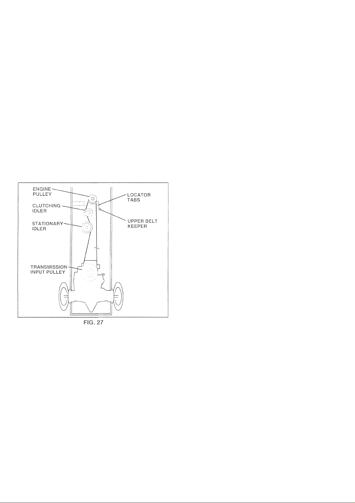
TO REPLACE MOWER BLADE DRIVE BELT (See Fig. 25)
The miower Diade drive Delt may De replaced without tools
Park the iracfor on level suriace. Engage parking brake.
20
WITH PARKING BRAKE "ENGAGED”
NUT"A”
. JAM NUT
\
imi
/
DO NOT TOUCH THIS NUT, IF FURTHER BRAKE ADJUST
MENT IS NECESSARY CONTACT YOUR NEAREST AUTHO
RIZED SERVICE CENTER/DEPARTMENT
FIG, 26
• OPERATING
ARM
Page 21
srRvir.f mv-
TO R
iSiP-p
Hark the thictor on level su
For assistance, there is a fc
bottom side of iett tootrest.
• Remove mower (See "1
» Remove upper belt keeper,
« Remove belt from stationafy idler and clutching idler,
• Pull belt slack toward rear of tractor. Carefully remove
• Pull belt toward front of tractor and remove downward
• Install new belt by reversing above procedure,
iMPORTANT; MAKE SURE UPPER BELT KEEPER IS
POSITIONED PROPERLY BETY/EEN LOCATOR TABS,
:PI
.ACE MOTION DRIVE BELT
■in
ge parking brake,
)n guide decal on
Lly|{ VE MOWER" in this
______
belt upwards from transmission input pulley and over
cooling fan blades,
from around engine pulley,
_____
______
,
TO ADJUST MOTION CONTRA rL . EVER (See
Ft , C)
The mrftion control ievei
adjustment should not t
If for any reason the mi iliui r oi i
position while at a selected spcv'd
friction pack located on ' transmission
• Park tractor on level suriace lot) tractor by turning
ignition key to "DFi
brake.
» Adjust motion control lever by tighfening adjustment
locknut one half (V'2) turn.
NO"
con'
adjL
Roa
ilBCt'swcii V -
....
posmon, and engage parking
y reasc
0 Î"'" '< o e^f essive. reverse the above
he effort to move the motion
img locknut 1/4 to 1/2 turn,
nt and repesnt procedure if
:t at the factory and
/
'er will not hold its
r be adjusted at the
ADJUSTMENT
LOCKNUT
FIG. 28
TRANSMISSION REMOVAUREPLACEMENT
Should your transmission require removal for service or
replacement, it should be purged after reinstallation and
before operating the tractor. See "PURGE TRANSMIS^
SION” in the Operation section of this manuai,
TO ADJUST STEERING WHEEL ALIGNMENT
If steering wheel crossbars are not horizontal (left to right)
when wheels are positioned straight foi"ward. remove steer
ing wheel and reassemble per instructions m the Assembiv
section of this mianual.
FRONT WHF FL TOEJN/CAMBER
The front wheel toe-in and camber are not adjustable on
your tractor. If damage has occurred to affect the front
wheel toe-in or camber, contact your nearest authorized
service center,'department.
21
Page 22

-f'RVSrj' ANfr^rMPK;rf\ilF-N-rc
TO R
( S
• Block up axle securely.
• I n g r i n g and w a s h e r s t o a I! o vv
not lose).
• d reassernbie,
• ks only: align grooves in rear wheel hub
no y| Insert square key.
• lers and snap retaining ring securely in
axle groove.
• Replace axle cover.
WASHERS
RETAINING
RING
\
AXLE COVER
TO START ENGINE WITH A WEAK BATTERY
(See Fig. 30}
CAUTION: Lead-acid batteries gener
ate explosive gases. Keep sparks, flame
A
If your battery is too weak to start the engine, it should be
recharged. If “jU'T'iper cables” are used for emergency
starting, follow this procedure:
IMPORTANT: YOUR TRACTOR IS EQUIPPED WITH A 12
VOLT NEGATIVE GROUNDED SYSTEM. THE OTHER
VEHICLE MUST ALSO BE A 12 VOLT NEGATIVE
GROUNDED SYSTEM. DO NOT USE YOUR TRACTOR
BATTERY TO START OTHER VEHICLES.
TO ATTACH JUMPER CABLES -
• Connect each end of the RED cable to the POSITIVE
(+) terminal of each battery, taking care not to short
against chassis.
• Connect one end of the BLACK cable to the NEGA
TIVE (-) terminal of fully charged battery.
• Connect the other end of the BLACK cable to good
CHASSIS GROUND, away from fuel tank and battery,
TO REMOVE CABLES, REVERSE ORDER -
• BLACK cable first from chassis and then fromi the fully
charged battery.
• RED cable last from both batteries.
and smoking materials away from bat
teries. Always wear eye protection
when around batteries.
I cortains a square key Do
SQUARE KEY
(REAR WHEEL ONLY)
FiG. 29
TO REPLACE HEADLIGHT BULB
• Raise hood.
• Pull bulb holder out of the hole in the backside of the
• Replace bulb in holder and push bulb holder securely
• Close hood.
INTERLOCKS AND RELAYS
Loose or damaged wiring may cause your tractor to run
poorly, stop running, or prevent it from starting.
• Check wiring. See electrical wiring diagram in the
TO REPLACE FUSE
Replace with 30 amp automotive-type plug-in fuse. The
fuse holder is located behind the dash.
TO REMOVE HOOD AND GRILL ASSEMBLY (See Fig. 31)
• Raise hood,
• Unsnap headlight wire connector.
• Stand in frontof tractor. Grasp hood at sides, tilt toward
• To replace, reverse above procedures.
POSITIVE
TERMiNAlC
! ' '“'1
............ ./
CHASSIS
POSITIVE
TERMINA
;
!
nu. ou
grill.
back into the hole in the backside of the grill.
Repair Parts section of this manual.
engine and lift off of tractor.
HOOD
FIVE
NAL
-CABLES
CHARGED
TTERY
1VE
NAL
HEADLIGHT
WIRE
'CONNECTOR
22
FIG, 31
Page 23

^LRvitF
ENGINE
TO ADJUST THROTTLE CONTROL iBLE
e.f
Th© throtti
,r JI iGn (- ,
ontrol
I [|f:
aw before loosening cable, if adjustment is
neret' im i. y m d l 'olio vS
‘ b'lh rum roirunnii' "/< tl n I'° c o ui< h lovnr
hoi 1 ( a (>^) t(i rhof - { |) t n It ( I ' Ic wh' rro'/t
mw I rri choke (h )'C'faJ poGiticn
• Check that holes “A" in governor control lever and hole
in governor plate line-up. If holes '‘A" are not aligned,
loosen damp screw and move throttle cable until holes
are aligned. Tighten clamp screw securely.
GOVERNOR
CONTROL LEVER
been preset at the
■necessary. Check a«
GOVERNOR
CONTROL PLATE
tory and
tmentas
• W I ' U I ) li ifi M •df
screw, turn idle mixtiite valve in
gme begins to die ano
until engine runs rough. Turn
between those two positions,
■¡en turn out
,,.-K
to
¡vunf midway
.....
'ttie lever.
ACCELERATION TEST -
• Move throttle control lever fr
position, if engine hesitates
valve out (counterciockwisej
continue to adjust, if necess
ates smoothly.
High speed stop is factory adjusted. Do not adjust damage may result.
IMPORTANT; NEVER TAMF’ER WITH THE ENGINE
GOVERNOR, YfHICH IS FACTORY SET FOR PROPER
ENGINE SPEED, OVERSPEEDING THE ENGINE ABOVE
THE FACTORY HIGH SPEED SETTING CAN BE
DANGEROUS. IF YOU THINK THE ENGINE-GOVERNED
HIGH SPEED NEEDS ADJUSTING, CONTACT YOUR
NEAREST AUTHORIZED SERVICE RENTER/
DEPARTMENT, WHICH HAS PROPER EQUIPMENT AND
EXPERIENCE TO MAKE ANY NECESSARY
ADJUSTMENTS,
FIG. 32
TO ADJUST CARBURETOR (See Fig. 33 )
The carburetor has been preset at the factory and adjust
ment should not be necessary. However, minor adjust
ment may be required to compensate fordifferences in fuel,
temperature, altitude or load. If the carburetor does need
adjustment, proceed as follows:
In general, turning idle mixture valve in (clockwise) de
creases the supply of fuel to the engine giving a leaner tueh
air mixture. Turning the idle mixture valve out (counter
clockwise) increases the supply of fuel to the engine giving
a richer fuel/air mixture.
IMPORTANT: DAMAGE TO THE NEEDLE VALVE AND
THE SEAT IN CARBURETOR MAY RESULT IF SCREW IS
TURNED IN TOO TIGHT,
PRELIMINARY SETTING -
• Air Cleaner assembly must be assembled to the carbu
retor when making carburetor adjustments.
• Be sure the throttle control cable is adjusted properly
(see above),
• With engine off turn idle mixture valve in (clockwise)
closing it finger tight and then turn out icounterdockvvise) 1 full turn.
THROTTLE
LEVER
IDLE SPEED
SCREW
IDLE MIXTURE
VALVE
FIG. 33
23
Page 24

V рге
ENGINE
ON; Nev6r stors thi? tractor with
lUTI
ie in the tank inside a building
fumes may reach an open flame
or :
bef<
It > a ,« ttlCli
siorinq in any enclosure.
TR/iC.TOR
R( nv \'f> pom I ,u lot kjt //nic t stnntjf d/ht n
mower is to be stored for a period of time, clean it thor^
oughly, remove all dirt, grease, leaves, etc. Store In a
f' <1 ai, ,ii 3
e ( Ira p , r-< f p If bf |r [ / í3 Pi R A KJ iKJf a n I hp iP ( 1 IÍ f nf r
Responsibilities section of this manual).
' in p ( nu' I pl c. belts, it necessary (See • < h 'u
placement instructions in the Service and Adjustments
section of this manual).
« Lubricate as shown in the Customer Responsibilities
section of this manual,
• Be sure that all nuts, bolts and screws are securely
fastened. Inspect moving parts for damage, breakage
and wear. Replace if necessary.
• Touch up all rusted or chipped paint surfaces; sand
lightly before painting.
BATTERY
• Fully charge the battery for storage.
• After a period of time in storage, battery may require
recharging.
• To help prevent corrosion and power leakage during
long periods of storage, battery cables should be
disconnected and battery cleaned thoroughly (see “TO
CLEAN BATTERY AND TERMINALS” in the Cus
tomer Responsibilities section of this manual).
• After cleaning, leave cables disconnected and place
cables where they cannot come in contact with battery
terminals,
• Be sure battery drain tube is securely attached,
• if battery IS removed from tractor for storage, do not
store battery directly on concrete or damp surfaces.
FUEL SYS
¡ТЕМ
FROM
^ CAR
EXPERIEFICt T-JDICA .ТЕЗ T Fi A T A L C
FUELS (C.
METHANO
TO SEPAF
SYSTEM C)F AN ENGi NE VSHiLE IN S‘
• Dram the fuei tank
• Start tise engine a nd iet It run Linti the fuel lines anc
t Y V
• Use fre;sh tue! nexi
ALLED GAS :OHOL OR USF
Li CAN ATS
lATION ANC
t
ACIDIC GAS CAN DAf
carbuT'etor are em;
use engine c
fuel tarIk or permai
'PACT MOISTUI
) FORMATION C
X'/
) I' C ci Г b Li г 01G Г C10 (A
nent damage mi
■: A';: ■! ; r;
R,.JEl FlLTE
.; I" . ; ' ,
10 H O L B L E N DEC
NO ETHANOL OF
TE VVHiCH LEADS
)F ACIDS DURING
dAGE THE FUEL
TO RAGE,
iner products m the
W occur.
NOTE: Fuel stabilizer is an acceptable aiternative in
minimizing the formation of fuel gum deposits during stor
age. Add stabilizer to gasoiine in fuel tank or storage
container. Always follow the mix ratio found on stabilizer
container. Run engine at ieast 10 minutes after adding
stabilizer to allow the stabilizer to reach the carburetor. Do
not drain the gas tank and carburetor if using fuel stabiiizer,
ENGINE OIL
Drain oil (with engine warm) and replace with ciean engine
oil. (See "ENGINE” in the Customer Responsibilities
section of this manuai).
CYLINDERS
• Remove spark plugtsi.
Pour one ounce of oii through spark plug hole(s) into
cylinder(s).
Turn ignitior
I urn ignition key to "START" position fora few seconds
to distribute
to distribute oil.
Replace with new spark plug(s).
OTHER
• Do not store gasoline from one sea
• Replace your gasoline can it your
Rust ana.'or din m your gasoline wi
• if possible, store your tractor indoc
give protection from dust and dirt,
• Cover your tractor with a suitable protective cover that
does not retain moisture. Do not use plastic. F'iastic
cannot breathe which allows condensation to form and
will cause your tractor to rust,
IMPORTANT: NEVER COVER TRACTOR WHILE ENGINE
AND EXHAUST AREAS ARE STILL. WARM.
24
Page 25

PROBLEM CAUSE
CORRECTION
Win not start
Hard to start
Engine will not turn over
1,
Out of fuel.
Engine not "CHOKED" properly
2,
3, Engine flooded.
4,
Bat,l spark plug.
D:rty air filter
5.
6 . Dirty fuel filter
7
Wafer in fuel
Loose or damaged vvinng. 3
3.
Carburetor out of adjustment. 9 -;ior'^ in Service Ad|usirnents
9
10, Engine valves out of adjustment.
1, Dirty air filter.
Bad spark plug.
2
Weak or dead battery. 3,
3,
4, Dirty fuel filter.
Stale or dirty fuel.
5,
6, Loose or damaged wiring.
Carburetor out of adjustment.
7,
8, Engine valves out of adjustment.
1, Clutch/brake pedal not depressed.
2. Attachment clutch Is engaged.
Weak or dead battery. 3. Recharge or replace battery.
3.
4.
Blown fuse.
Corroded battery terminals. 5,
5,
6, Loose or damaged wiring.
Faulty ignition switch.
7,
Faulty solenoid or starter.
8.
Faulty operator presence switch(es). 9,
9.
¡■■■Li iUf..'l i.i.lIlK.
Sf.-e "TO START ENG1NE3' in Operation seciioi'n
Í 2-
Wait several niinijies before attempting to stari.
/ -
Replace spark plug.
Cl in/mp'ar f' an iiin-i
5.
6. rTcolace fuel tiiter.
ruretor. :'eíiíí tank '.vith fresh
ei filter
' 1- 7 -H H t '
1C 5 e r V1 c e c e n t e r ' d e p a r t m e n t
1. Clean,4epiace air filter
O'
R6|3i:u.:t; spaiK olug.
4.
Replace fuel tiller.
ilterv
5, I '.vith fresh gasoline
Check all wiring.
6,
8.
1 ,
Dooress ciLitch'brake oedal
DIsengtrge attachment clutch
2,
4,
Replace fuse
Clean battery teriTiinais,
Check all wiring.
5,
dor" If' Service .Adjusiiriei'iis
service center'deparíri'ierü
7, Check/replace luniiion switcki.
8, ChecOreplace solenoid or starter
Contact an authorized service center'department.
Engine clicks but will not 1, Weak or dead battery.
start 2.
Loss of power
Corroded battery terminals. 2.
Loose or damaged wiring. 3.
3,
4. Faulty solenoid or starter.
1. Cutting too rnuch grass.doo fast.
2, Throttle in "CHOKE" position.
3. Bulld-up of grass, leaves and trash under mower. 3
4 Dirty air filter.
Low oil level.Oirty oil
5.
Faulty spark pli,iq 6
6
7'
Dirty fuel filter.
8, Stale or dirty fuel. 8.
Water in fuel.
9,
Spark plug '.vire icose Ci
'0,
1 ',
Dirtv engine air screen iins
9 Dirtv cioggeo mutfler
Loose or damaged '.virinq ' ■?
' 3
Carburetor out of adiusfment
1:3 Engine ','aives cut ot adius:me:"i •5
Excessive vibration
7’
3
25
1 ,
Recharge or replace battery.
Cleari battery ierminnls
Check all wiring.
4,
Check, replace solenoid or starter.
fion reduce speed
2
.1
ChecK Olí iO'L^w! nnanu'O
“■
9,
11 J ."i I 3 i M 1 v; Í > 1 ; ' J : ' ■ ; i i i : i ; L: Ì - ; i ; vj i
' 2
dieclace cimie ■" 'inte" luaoe ecu
2. 'Replace rdtme 'manure
3
Tiuhten lecse rarLs.. ergnmee damaueu :'ni'*r
‘.O' ¡"■ousin;,;
r'09 snnrK nino
1 '.vifn fresri gasoline.
lureior. "etili iane '.'.'i'l'
auc Oiuc: '.M-e
•ten' Ser-wcn .-\U"..sc"m :,-■
10 : 1 c 0 7: I e r u e i: a ra ’ : -n ' :
Page 26

^ROBLEr
Enqine contii
USE
CORRECTION
witn atta cn m e nt clutcn
eng ag e d
Poor cut - uneven 1. Worn, bent or loose blade
,2, iMovver deck n(.)t level,
3, B^uildup of pr,a,ss, leaves, and trash under rnovver
4, Bent blade mtindrel,
5, Clogged mower deck vent Itoles from buildup of
grass, leaves, and trash around mandrels.
Mower blades will not
rotate
1, Obstrurti Hi 1', clutch Mechanism,
2, Worn rive belt,
3, Froze
4, Froze
Poor grass discharge 1, Engir 00 slow,
2, Trave to fast,
3, Wet c
4, ivlowe it level.
5, Low/t 3 air pressure.
6, Worn oose blade,
7, Build! s, leaves and trash under mower,
8, Mower ci' r belt worn.
9, Blades i ii i , .triy installed.
10, Imprope i disused.
11, Clogged mi mr deck vent holes from buildup of
grass, leaves, and trash around mandrels.
department.
Replace oi;iu= .uwen oiaae rroii
2, .-.evei mown: .c,',,«
3. Clean unoc's.iii: ,n rncv.M itousn'Ki
4 Replace mane ■’vn'iore
5, Clean aroi.ino '"andreC va cnen vent doles
2.
3,
4,
1 , " "
................
' csition,
2,
3,
4,
5, 3,
6, blade bolt
7, ig.
8,
9. R( imtall b.ade- maip udde (M • n,
10. Will I LdiclUtdb MibitfU ill ti HC:> ["nSnuai.
11 - Clean around mandrels to open vent holes.
Hea d lig ht (s ) n ot w or ki ng
(if so eq ui pp ed )
1. Switch is "OFF'2
2. Bulb(s) burned out,
3. Faulty light switch,
4. Loose or damaged wiring.
5. Blown fuse.
Battery wit! not charge 1. Bad battery cell(s),
2. Poor cable connections.
3, Faulty regulator (if so equipped).
4, Faulty alternator.
Loss of drive 1, Freewheel control in "disengaged" position.
2. Motion drive belt worn, damaged, or broken,
3 Air trapped in transmission dunn'i sliipment
or servicing.
Engine "backfires"
when tur nin g en g in e
' Engine throttle control not set at "SLOW
position ior 30 seconds before stepping engine
"OFF"
1, Turn switch "OC"
2, Replace bulbis.
3. ChecCreplace nuni switcit
4. Check wiring ana connections.
5 Repkice tuse
1. Ro| ' ti ' natV'
2. Clif k lean m nne.dions,
3. Ri.place legi.iat i
4. Replace alien la 1 ii
1 lea" Dosition
zl . . w.:, . 1 w.'l n 1 . , ; ..1..
1 0’.',
26
Page 27

SCHEMATIC
—Y A T
AMMETER
(OPTIONAL)
BATTERY
FUSE 30 AMP,
CLUTCH/BRAKE
(PEDAL UP)
STARTER
SOLENOID
SEAT SWITCH
;NOT OCCUPIED)
POSITION
OFF
RUN./LIGHT B - L
RUN
START
CIRCUIT ■■MAKE"
G -X M * L
3 - ' NONE
NONE
A Y
NONE
HOUR
METER
(OPTIONAL)
FUEL SHUT-OFF
SOLENOID
1.
FUEL
LINE ^
NOTE
ATT’MENT CLUTCH
(CLUTCH OFF)
IGNITION
LIG
5 AÍ
UNIT
\
DIODE
GROUNDING
CONNECTOR
.-X PLUG
■ gap
(2 PLUGS ON
TWIN CYL, ENGINES)
;:s VOLTS ac din, v seoc npy
CHARGING SYSTEM DISCONNECT
AC MIN A 3600 RPM lUGHTS OFP^
YOUR TRACTOR IS
EQUIPPED WITH A SPECIAL
ALTERNATOR SYSTEM.
..
THE LIGHTS ARE NOT
CONNECTED TO THE
BATTERY, BUT HAVE THEIR
OWN ELECTRICAL SOURCE,
BECAUSE OF THIS, THE
■lEADLlGH
BRIGHTNESS OF THE LIGHTS
WILL CHANGE WITH ENGINE
SPEED. AT IDLE THE LIGHTS
WILL DIM, AS THE ENGINE IS
SPEEDED UP, THE LIGHTS
WILL BECOME THEIR BRIGHTEST,
NON-REMOVABLE
CONNECTIONS
CONNECTIONS
WIRING INSULATED CLIPS
NOTE: IF WIRING INSULATED CLIPS WERE REMOVED FOR
SERVICING OF UNIT. THEY SHOULD BE REPLACED TO
PROPERLY SECURE YOUR WIRING
SPARK
ALTERNATOR
REMOVABLE
27
Page 28
REPAIR PARTS
I p ^ ^
,hA'- ifVP-... t . V-
22
21
-r.
70
,i!i.mi
16
... /
■ 6
\
3 .
■%
fiiitfeiiiir:
28
Page 29

REPAIR PARTS
ELECTRICAL
KEY PART
NO. NO.
1
144925 Battery 12 Volt 25 Amp
2 74760412 Bolt Hex Hd 1/4^20unc X 3/4
3 19091016
4
10040400
73220400 Nut Fin Hex 1/4-20 Unc
6
7 109238X Tube Plastic 12" Rear Battery
8 156417
9 109596X
147688
15
16 153664
19 10090400
20 73350400 Nut Jam Hex 1/4-20 Unc
21
136850
22 4152J
24 4799J Cable Battery 6ga 11" Red
146147 Cable Battery 6 Ga 44" Red W/16 Wire
25
26 108824X
4207J Cable Ground 6ga 12‘ black
28
29 121305X
30 140301
124211X Nut Ignition
31
32
141226
33 122147X Key Ign Molded Generic
156442 Harness Ign
40
41
71110408
42
131563
43 145673
44 73640400 Nut Keps Hex 1/4-20 Unc
48 140844
52 141940
70 140422 Harness Engine
DESCRIPTION
Washer 9/32 X 5/8 X 16 Ga
Washer Lock Hvy Helical 1,'4
Case Battery
Clamp Hose Oiive
Fastner Snap-In
Switch Intik Push-in
Washer Lock 1/4
Harness Socket Light
Bulb, Light # 1156
Fuse 30 Amp Auto Green
Switch Plunger Nc Gray
Switch Ign 4 Pos W/L P/L
Cover Sw Ignition
Bolt Fin Hex 1/4-20uncx1/2
Cover Temminal Red
Solenoid
Ammeter Adapter Rectangular
Protection Loop
NOTE: Ail component dimensions given in U.S. inches
1 inch = 25.4 mm
29
Page 30

REPAIR PARTS
CHASSIS
30
\
■24
ls
1?.
•24
58
12
28
29
/
/
14
26
26
25
31 ^
Il
14
15-
\i ^
26
25
6
•16
-3
-8
37
140
\
20
37
14-
4.
13
33
10
38-
35
30
/■
39
34
' 3
/
14
26
Page 31

REPAIR PARTS
TRACTOR
KEY PART
NO. NO. DESCRIPTION
1 155051
2 140356
17490612
3
4 19131216
155272
5
155923 Saddle Fender Shift Flat
6
8 155138
9 147627X011 Dash Private Label
10 72140608
11
155927 Panel Asm, Dash Lh
12 145660
155934X010
13
14
17490608
74180512
15
16 73510500
139394X428 Hood Pnt Steel Private Label
17
18 126938X
156437
20
124028X
23
24 74780616
19131312
25
73800600
26
28 157373
140273 Lens Grille Private label
29
140001X428 Fender
30
31 136619
105476X428 Footrest Pnt. LH
33
105475X428
34
72110606
35
37 17490508
139886
38
139887
39
51 73800400
19091416
52
144697 Bracket Grille LH
53
17030814
54
144696 Bracket, Grille RH
55
57 74780412
150127
58
158418
140
5479J
MODEL NUMBER CHD145H42A
Chassis VVIdmt.
Drawbar Stretch 94
Screw Thdroi, 3./8-16 x 3/4 Ty^l t
Washer 13/32 x 3/4 x 16 Ga.'
Bumper Hood/Dash
Clip Retainer SlideOn
Bolt RdHd Sqnk, 3/8G6Uncx1
Clip Tinnerman Grile P/L
Panel Dash Rh
Screw Thdroi. 3/8-16x1/2 Ty-Tt
Screw Mach Trhd 5/16-18 Une x 3/4
Nut Keps 5/16-18 Une
Bumper Hood
Plate Mtg Battery/Fuel Tank
Bushing Snap Nyl. BIk Fuel Line
Bolt Fin Hex 3/8-16 Une x 1 Gr. 5
Washer 13/32 x 1.3/16 x 12 Ga.
Nut Lock Hex w/lnsert 3/8-16 UNC
Grill Private Lable BIk
Bracket Fender
Footrest Pnt. RH
Bolt RdHd Sht. Sqnk, 3/8-16 x 3,4
Screw Thdroi 5/16-18 x 1/2
Bracket Asm. Pvt. Lh Mwr. Rear
Bracket Asm. Pvt. Rh Mwr. Rear
Nut Lock Hex W/lns, 1/4-20
VA/asher 9/32 x 7/8 x 16 Ga.
Screw Lock Spider #8 x 7/8
Bolt Fin Hex 1/4-20 x .75
Air Duct Private Label
Bracket Suspension Front
Plug Btn BIk
NOTE: All component dimensions given in U.S, inches
1 inch = 25,4 mm
31
Page 32

REPAIR PARTS
DRIVE
69
88
87
86
81
83-
125 .. 100
84
100
52
/
15-
52
77
126
10
, A
30
32
61
96
T(S/. f. jiVlI.M, ‘ -ii
59
42
'82
1-. _____
8
13 ; / / 18
123^-'
\ ^
95,
21
\ 87
86
-----
^124 fe
-88
'i ,1
'1 / /
/ 30 ^
\
122
4 ¡r
7 :7
/
61
/ 1,
62 ;
35 /
61 - '
1 2i
\ 24
19
41'
36
42'
56-
38-
34
28
42-
40-
42-
39-
,51
51
63
19
72
66
70 '
116
ii
- 65
64
I'
55
^50
50-
121
48
118
27-
26
51
49'
47-^
26-
37
51-
36
/
/
35
'53
74
22
26
27
Page 33

REPAIR PARTS
TRACTOR
DRIVE
PART KEY
NO.
1
146682 Spring, Return Brake
2
121520X Strap Torque
5
17490512
6
141003 Rod Shift Hydro LT
8
76020416
10
74550412 Bolt 1/4-28 Unf Gr. 8 W/Patch
13
74490544 Bolt Hex FIghd 5/16-18 Gr, 5
15
74780616
18
73800600
19
106933X Knob, Round 1/2-13
21
130804 Rod, Brake
22
24 73350600
106888X Spring, Brake Rod
25
19131316
26
27 76020412
145204 Rod, Parking Brake
28
29 71673
130807
30
74760512 Bolt Hex Hd 5/16-18 Unc x 3/4
32
34 155071
120183X Bearing, Nylon
35
19211616 Washer
36
37 1572H
123674X
38
74760644 Bolt
39
4470J
40
154777 Keeper, Belt, Idler
41
19131312
42
127783
47
154604
48
123205X
49
74760624 Bolt
50
73680600
51
73680500
52
105710X Link, Clutch
53
105709X
55
DESCRIPTION
Transaxle (See Breakdown)
Peerless Model 205^0278
Screw Thdrol 5/16M 8 x 3/4
Pin Cotter 1/8x1 CAD
Bolt Fin Hex 3/8-16 Unc x 1 Gr, 5
Nut Lock Hex W/Wsh 3/8-16 Unc
Nut, Hex Jam 3/8-16 Unc
Washer
Pin Cotter 1/8 x 3/4 CAD.
Cap, Parking Brake
Bracket, Transaxle
Shaft, Foot Pedal
Pin. Roll
Pulley, Idler, Flat
Spacer, Split
Washer 13/32 x 13/16 x 12 Gauge
Pulley, Idler, V-Groove
Bellcrank Assembly
Retainer, Belt
Nut Crownlock 3/8-16 UNC
Nut, Crownlock 5/16-18 Unc
Spring, Return, Clutch
PART
NO. NO.
74760620 Bolt Hex 3/8-16 X 1-1,,'4
56
57 156971 V-Belt, Ground Drive
59 140312 Keeper. Center Span
17490612 Screw Thdrol, 3/8-16x3/4 ] y, FT
61
62 8883R
63 140186 Pulley, Engine
64 71170764 Bolt Hex 7/16-20 X 4 Gr. 5
10040700 Washer
65
66 154778 Keeper Belt Engine
69 142432
70 134683
72 19132012 Washer 13/32 x 1 -1 /4 x 12 Gauge
74
156972 Spacer, Axle PVST
75 121749X Washer 25/32 x 1-1/4 x 16 Gauge
76 12000001
77 123583X Key, Square
78 121748X
81 158461
82 123782X
19171216 Washer 17./32 x 3/4 x 16 Ga.
83
84
158286
86 71208
19212016 Washer 21/32 x 1-1/4 x 16 Ga.
87
12000008 Ring Klip #5304-62
88
89 151147 Console, Shift
95 156970
96 4497H
100 19111216
113 127285X
72110610 Bolt Rdhd Sq. Neck 3/8-16 x 1,25
116
154774 Spacer Bellcrank
118
154419 Nyliner Clutching STL
121
122 156963
19091016 Washer 9/32 x 5/8 x 16
123
124 156967
74780516 Bolt Fin Hex 5/16-18 Unc x 1
125
126 1685H Nut Lock 5/16-18 Unc
NOTE: Ail component dimensions give in U.S. inches
1 inch = 25,4 mm.
DESCRIPTION
Cover, Pedal
Screw
Keeper Beit Engine
E-Ring
Vdasher 25„'32 x 1-5/8 x 16 Gauge
Shaft Asm. Cross Hydro 18" Tires
Spring Torsion T/A
Rod, Tie PVST 18"
Bushing Rod Strig, 629/632 ID
Rod Asm Bypass PVST
Retainer Spring 1" Zinc/Cad
Washer 11 /32 x 3/4 x 16 Ga.
Strap Torque LH LT
Plate Bypass PVST
Spring Return PVST
33
Page 34

REPAIR PARTS
ASSEMBLY
, - - IV. .iWi ; 1
"63
- 11
■"■ 39
-37
-36
20
22.,
29^
- 19
68 *5'''
13
46^
7 ..„
9-.-.
29
29
28
30
34
Page 35

REPAIR PARTS
TRACTOR
BLY
KE Y PA RT
NO .
1 140044 Wheel Steering Ayp/P/L Bik
2
3
4
5
6 121748X 7' i ler :'b> 2 X 1 3
~J
8 12000029
9 3366R 1 r ii. j '() h o P
10 156438
11 10040600 j 1 1 hi 1 L(’/ ' 1 tv ^1 ' 'jf 5;5
13
15
17 156546
18 57079
19
20 126684X
22
23 127501
25
26 126847X
27
28 19131416
29 17490612
30
32 130465
36 155099
37 152927
38
39
40
41
42
43
44 153720
46
47
51
54 74780520
62
63
65 154780
66
67
68 154429 Brace Axle
MODEL NUMBER CHD145H42A
NO . DESCRIPTION
154427 Axle Asm Fr LT W.-'qzks 38/42
154422
154433
6266H V/ ,i' herThn ^\ !' ^ \
19272016 w n r' T •: X 1 1 a
154779
73901000 k t L ick 1 lO ge t - m L nc
124035X upc nt 5h 4t
71200410 t ( i-A ^ ( 4 I 5 1 X 5/8
154406
136874 Gear Sector 22 Teeth
76020412 Pin Cotter 1/8 X 3/4 Cad
140045 Cap Wheel Steer Ayp
19133808
7810H Lock Nut
100711L
145054
121749X
121232X
6855M Fitting Grease
73800500 Nut Lock Hex W/lns. 5/16-18 Unc P
156594 Kit Steering Asm Service
74780616
154404
74781044 Boit fin Hex 5/8-11 UNC x 2-3/4
Sipindle Asm LH
^ tnidle Asm RH
III R 1 [ 9 ' .0 4
1 m l i . m
1 t ¡rii lo A le Till r
. , . It Ac,11 vt j P tiv li e 1 , ibel
V''. I ir !him t 51 hx n (, ; 033
' V/ , hn 111 ' I' t ' 062
‘1 fi rn F ittm n
Lr 'kp'cic'ling
bushing Link Drag BIK Lr
Washer 13/32 x 7/8 x 16 Ga.
Screw Thdrol 318-16x314 Ty-tt
Rod Tie Wire Form 19 75 Mech
Bushing Steering
Screw
Washer 13/32 x 2-3/8 x 8 Ga
Adapter Wheel Strg
Boot Shaft Steering
Washer 2.5/32 X 1-1 4 X 16 Ga
Shaft Extension Steering Non-Adi
Cap Spindle FrTop Bik
Bolt Fin Hex 5/16-18 Unc 6 x 1-1/4
Bolt in Hex 3/8-16unc x 1
Gr. 5
Spacer Axle
Bearing Arm Pittman
NOTE: Ali component dimensions given in LJ.S, inches
1 inch = 25.4 mm
35
Page 36

REPAIR PARTS
DECALS
t r 4- --ÌV. 1 -yir-U' ur- ;
KEY
NO.
11
13
15
16
1
2
3
4
5
6
7
8
PART
NO.
158167
145005
158037
158169
158172
157140
101892X
158038
158176
158168
136832
158166
WHEELS & TIRES
DESCRIPTION
Decal,
Decal
Decal
Decal,
Decal,
Decal,
Decal
Decal
Decal,
Decal
Decal
Decal
Fender St Lawn Tret
Bat Dan/Poi P/L Symbols
Hood RH
Deck
Engine
Danger Fender(E/F)
Clutch/Brk (E/F)
Hood LH
Seat Replacement
Wheel Steering
V-Belt Schematk
Fender
4,10
3,9
11
KEY
NO,
19
Available accessories (not included with tractor):
KEY
NO.
10
11
NOTE; AH component dimensions given in U,S mene;
PART
NO.
156993
138311
142341 Decal Drawbar Cntl. Mut Hyd
157257 Manual Owner"s (Eng)
159414 Manual Owner's (Fr)
C42
LSB42
LC05 Wheel Weights
LBD48 48" Snow Blade
LA018 Tire Chains
MK42
PART
NO.
59192
1
65139
2
106222X
3
4
59904
106732X427 Rim Asm 6" (Front White Service)
5
278H
6
9040H
7
106108X427
8
106268X Tire R Ts 18x9 5-8 C Semice
9
7152J
104757X Cap Axle BIk 1 50 X 1 00
144334 Sealant, Tire ¡10 oz. Tube)
1 inch := 25,-I mm
DESCRIPTION
Decal, Saddle Oper. Inst. Hyd, E/F
Decal Handle LiR Height Adz
Grass Catcher
42" Snow Blower
Mulching Kit w/Biades
DESCRIPTION
Cap Valve Tire
£1ten, Valve
Tire F Ts 15 X 6 0 “ 6 Service
Tube Front (Service Item Only)
Fitting Grease (Front Wheel Only)
Beanng Flange (Front Wheel Only)
Rim Asm 8" (Rear White Service)
Tube Rear (Service Item.Only)
36
Page 37

REPAIR PARTS
TOLY
--IV[< .ur. [ .Nir hi [1 .1 ^hH''
18
9-
14.
7.
22
21
■16
25
-15
23
^4
3
KEY
NO.
10 155925
12 121246X
13
PART
NO.
1 140116
2 140551
3 74760616
4
19131610
145006
5
73800600
6
7 124181X
17490616
8
19131614
9
121248X
DESCRIPTION
Seat
Bracket Pivot Seat 15 134300 Spacer Spin 28x 96 Yel Zinc
Bolt Hex 3/8 - 16 X 1 16 121250X
Washer 13/32 X 1 " 17 123976X
Clip Push-In Hinged 18 124238X Cap Spring Seat
Nut Lock Hex w/Wsh 3/8 - 16 Unc 21 153236 Boit Shouider 5/16-18 UNC
Spring Seat Cprsn 2 250 BIk Zi 22 73800500 Nut Lock Hex W/lns 5/16-18 Unc P
Screw Thdrol 3/8-16 X 1 Ty-tt
Washer 13/32 X 1 X 14 Ga
Pan Seat
Bracket Mounting Switch
Bushing Snap BIk Nyl 50 Id
KEY
NO.
14 72050411
23
24
25 127018X Bolt Shoulder 5/16-18 X 62
26 10040800 Washer Lock Hvv Hid Sor 1/2
NOTE: Alt component dimensions given in U.S, inches
PART
NO.
74780814 Bolt Fin Hex 1/2-13 X 7/8 Gr 5
19171912
1 inch = 25.4 mm!.
DESCRIPTION
Bolt Rdhd Sht Nk 1/4-20 x 1-3/8
Spring Cprsn 1 27 BIk Pnt
Nut Lock 1/4 Lge Fig Gr 5 Zinc
Washer 1 7 32 X 1 -3-4 6 X 12 Ga
37
Page 38
REPAIR PARTS
LIFT
13
ir.A,b( i, iihi
\
11
12
19
19
KEY
NO.
10
11
12
PART
NO.
1 136973
145117 Shaft Asm Lft RH 15
2
105767X Pin Groove
3
12000002 E^nnq Truarc #5133^62
4
19211621 VYasher Pltd 21/32 X 1 X 21 Ga 18
5
120183X Bearing Nylon
6
7 109413X
124526X
8
122512X -Spring Compression
139865
139866
DESCRIPTION
VOire Asm Inner VV/Plunger 13
Grip Handle Matte
Button Plunger Black
Link Lift LH
tank Lift RH
/
20
15
1? 20 T \ \, V
r
20
15
KEY
NO.
16
17
19
20
31
32
NOTE: All component dimensions given in U.S.
PART
NO.
4939M
127218
73350800
130171 Tnunnion BIk Enc
73800800
139868
3146R
140302
73540600
1 inch = 25.4 mm
DESCRIPTION
Retainer Spring
Link Front
Nut Jam Hex 1/2H3 Unc
Nut Lock VJhNsh 1,/2H3unc
Arm Suspension Rear
Retainer Spring
Bearing Pvt. Lift Spherical
Nut Crovvniock 3/8~24
1 .T
inches
38
Page 39

REPAIR PARTS
ENGINE
( r.pi ■, , Mlnpi- . ► . .
2 --
32-,
31
78
^
------------------
44 \
'46
■ 33
"'37
. ^16 / /
'33
/G
14 /
15 1 i'
38
3 /i.
72
81
62
13
40
29
23
OPTiONAL EQUIPMENT
Spark Arrester
KEY
NO.
13 272293
1 4
15 13200300
16
23 156123
29 137180
31
32
33
PART
NO. DESCRIPTION
1
140310 Control Th/ch 23.5 Lh Flag 35 17490512 Screw Thdroi 5./16-18 x 3/4 TXT
2 17720410
3
Screw Hex Thd Cut 1/4-20x5/8 T 37 137040
Enqine(See Breakdown) Briggs 38
Model 287777
4
137352
Muffler Exhaust B&S 40 124028X
Gasket Eng 1 313 Id Tin Plated 44
13280324 Nipple Pipe 3/8 Npt X 3"
Elbow Std 90 Degree 3./8-18 Npt 62
11050600
Washer Lock Eat Tooth 3/8
Shield Browning
Kit Spark Arrestor (Fiat Semi
140280
140527
123487X
Tank Fuel Front 2.00 Gai
Cap Asm Fuel
Clamp Hose BIk
KEY
NO.
PART
NO.
DESCRIPTION
Line Fuel
........
Plua Oil Dram (Order From Engine
Manufacturer!
Bushing Snap Nyl BIk Fuel Line
17490412
Screw Hexwsh Thdroi 1,/4-20x3-4
46 19091416 Washer 9./32 X 7/8 X 16 Ga
10040500
Washer 5H6
72 71070512 Screw 5.16-18 X 3/4
78 17490620 Screw Thdroi 3/8-16x1-1,-4 TYTT
81
128861 Nut Flange 1.4-20 Starter Nut
NOTE: All component dimensions given in U.S. inches
1 ¡neh = 25.4 mm.
V,
.35
39
Page 40

REPAIR PARTS
IV10\
n 1 .’t'- H . . u i r i ‘ r r F I l i r M . I / -
72^
74/
71^
45
76
75 "
73
77
43
\7
44-^
45...
¿7 r--f.
7 I -
81 82-
\ 1' ;
/
•■•V.
\ 7 ;
67
■ 3?:
/46
53
1 52
/1 '
48-'^ ;
/^1
79 L
iO
'
\
-36
'132
56_ :
55v ^
51'> ■
120
117-
5 -
.116
119
113 111
118
19 ■
21
21
22
23
24
25
26
28
29
121
/
13-
10_
9
114^"
-12
128 i
___11 115 ■ -
118
119
113
112
117
120
116
27
40
Page 41

REPAIR PARTS
TRACTOR -
l\ \4 2A
MO\
KEY PART
NO. NO.
1
144393
2 72140506
138017 Bracket Asm Fr Sway Bar 38/42 53
3
4 138440
4939M
5
130832
6
850857
8
10030600
9
DESCRIPTION
Mower Housing
Bolt Rdhd Sqnk 5/16-18unc X3/4 52 139888
Bracket Asm Deck 42" sway Bar
Retainerspring
Arm Suspension Rear
Bolt 3/8-24 X 1 1/4 58 140086
Washer Lock Hvy 3/8 59
10 140296 Washer H ar d Blade M o w er Vented 67 106932X Knob Rd
11 138498
12 129895
13 137645
128774 Housing Ma n dre l Ve nt ed 73 127847
14
15 110485X
16 140329
17 72110610
18 72140505
19 132827
20 136888
736 80 50 0 NutC ro w nlo ck 5 /16 -1 8 U NC 80 153701
21
22 13 47 53
131267
23
24 1 05 30 4X
123 71 3X
25
26 1 10 45 2X
27 1 30 96 8
28 1 91 11 01 6
29 131491
138776
30
129963
31
32 153535
33 137266
72110614 Bolt Rd h d 3/8-16 un c x1 -3/4 Gr. 5
34
35 133835
131 49 4 Pu lle y I dle r Fla t 3 0 60 119 19121414
36
37 19131316
40 73680600
41
133551
43 140083
44
140088
4497H
45
46
137729
133944
48
49
155066
50 131340
Blade 68 144200
Bearing Ball
Shaft A"sm WAower Bearing
Bearing Ball M a nd re l 74
Stri pp er Mower V en ted
Bolt Rdh d Sq n k 3/8-16 X 1-1/4
Bolt R dh d Sq n k 5 /1 6- 18 X 5/ 8 77
Bolt Shoulder
Baf fle V or tex 4 2 79
Stif fen e r B ra ck et 42 " d e ck 81
Bracket DeflectorMower42"
Cap S le ev e 80 x 1 1 2 B lk M ow e r
Spr in g T o rsi on D efle c to r 2 52 84 15 60 84
Nut Pus h Ph o s & Oil
Shie ld D e fle cto r M o w er 42 " B lk 9 2
VLasher 11/3 2 X 5/8 X 1 6 Ga 1 11 155197
Rod H in ge 4 2" 6 75 W ig 112 155198
Scr ew T hd ro l H e x H e ad Z inc M w r
Wa sh er S pa ce r M o we r Ve nt ed 114
Pull ey M a nd re l 4 2" 115 72110504
Nut 9/1 6 T o p L oc k FI ng 116 4898H
Fas tn er Ch ris tm a s Tre e
Wa sh er 13 /3 2x 1 3/1 6 x 1 6G a 120 19171512
Nut C ro wn lo ck 3/ 8- 16 U NC 121 143723
Rod Piv ot W /n ibs 128
Rod C lu tc h S e co nd ar y W / nib s 132
Guard Mandrel LH Black
Spring Retainer r Zinc/cad
Screw Hex Thd Cut
Washer Hardened Smaller
Roller Asm Cam Follower 42" dec
Bolt Shoulder 10-24 Zinc Gr 5 42"
KEY PART
NO, NO.
51 69180
DESCRIPTION
Nut Lock #10-24 Unc
Bolt Shoulder 5,16-18 Unc BIkz
131845X900 Arm Asm Pad Brake
54
133943
55 155046
56 122052X
Washer Hardened
Arm Idler 42" mower LT/YT
Spacer Retainer Ргтт Mower
Spring Torsion Brakes 42"
141043 Guard TUV Idler
V-Belt Mower
71
142427
Rod Clutch Primary 38/42
72 131870 Spring Return
Arm Clutch Sec o nd ary
121748X
75 12000029
76 128903
Washer 25/32 X 1 -5/8 X 16 Ga
Ring Klip #t5304-75
Bolt Shoulder3/8-16 Unc 1 44
127845 Keeper Sprin g 4 00 0
78 154809
127498
Lever Asm Clutch Primary
Bushing 747 O d X 79 4 Lg B ras s
Spring Clutch Mower
73350600
82 142028 Trunnion Adj
83 120958X
85 72 1 40 61 8
Nut Hex Jam 3/8-16 Unc
Wa sh er S int er ed
Kee p er Be it idl er
Bolt R dh dS qn k 3/ 8- 16 x2 -1 /4
73800600 Nut Lock He x w/lns. 3/8-16 UNC.
Bracket Guage Wheel Lh
Bracket Gauge Wheel Rh
113 17490512
73510500
Screw Ghdroi 5/16-18 x 3/4
Nut Keps 5/16-18 UNC
Bolt Carnage 5/16-18 UNC x 1-1/2
Bolt Shoulder
117 105455X
118 73930600
Wheel Gauge
Nut Centerlock 3/8-16 UNC
Washer 3/8 x 7/8 x 14 Ga.
Washer 17/32 x 15/16 x 12 Ga.
153390 Washer Felt
Bra ck et E xtr ud ed G ua ge Wheel
19132203 Washer 13/32 x 1-3/8 x 3 Ga,
130794
Mandrel Asm Service (Includes Key
Nos, 8-10, 12-15. 31 and 33)
144783 Deck Sere (Std. Deck - Order
seperately gauge wheel
components Key Nos. 111-1211
NOTE: Ail component dimensions given in U.S. inches
1 inch = 25.4 mm
41
Page 42

REPAIR PARTS
TRANSAXLE
180.
189
REF PART
NO. NO.
790075
36
790007
37
799021
38
786026
39
39B 798033
792076A
40
41 790085
792073
42
792085A
42A
792075
43
4445790025
786066
790086
46
DESCRIPTION
Brake Disc
Brake Pad Plate
Brake Pad (pkg of 2)
Dowel Pin
Belt Guard
Flat Vkasher
Brake Lever
Screw. 1/4-20 x 1-1/4"
Screw. 1/4-20 x 2-1/4"
Locknut, 5/16-2.4
Brake Pad Holder
Spacer
Brake Lever Bracket
41
43
REF PART
NO. NO.
71 788069
71 A 792162
79 792144
87 788035
180 730229A
189 792168
189A 792169
190 792150
191 792151
208B 798025
209 798024
Parts must be ordered from Tecurnseh Products Co.
NOTE: All component dimensions given in U.S, mck
1 inch = 25.4 mm
DESCRIPTION
: n 1 Cut Ring
9/16"
wl • -11 0./8"
80W90
Drive Screw #6 x 1/2"
Screw, 10-32 X 1/2"
Lockwasher
Nut. 7'16-20
kan./Coupiing (Incl. 189 & 189A
Control Lever
42
Page 43

WICE
Т"! I»!\/1SEH
Issued January 1980
Revised January 1991
JARRAN
E ( m;vi I
LIMITED WARRANTIES
FOR
NEW PEERLESS GEAR POWER TRAIN COMPONENTS
A. Products Warranted
Peerless Gear and Machine Division of Tecumseh Products Company {“Tecumseh"J subject to the limitations contained below, will,
at its option, repair or replace, without charge for parts or labor only, any part of a new Power Train Component (which as used herein
means and includes the iransaxle, gearbox, transmission, differential and right angle drives, and any part of the Power Train Component),
EXCEPT any new Power Train Component incorporated in equipment used for commercial or rental purposes, which is found upon
examination by any Tecumseh Authorized Service Outlet or by Tecumseh's factory in Grafton, Wisconsin, to be DEFECTIVE !N
MATERIAL AND.'OR WORKMANSHIP if receive-d by Tecumseh or a Tecumseh Authorized Service Outlet for such examination within
TWO YEARS from the date of sale to the original consumer purchaser of Peerless Senes 820, 900, 910, 915, 920, 9,30 transaxies and
Series 1100 angle drive and ONE YEAR for ail other Peerless products. New Power Train Components incorporated in equipment used
for commercial purposes are warranted in the same manner and to the same extent EXCEPT such Power T rain Components are warranted
for NINETY (90) DAYS ONLY, andmustbereceivedbyTecumsehorbyaTecumseh Authorized Service Outlet for such examination within
90 days from the date of sale to the original purchaser. New Power Train Components Incorporated in equipment used for rental purposes
are warranted in the same manner and to the same extent EXCEPT such PowerTrain Components are warranted forTHIRTY (30) DAYS
ONLY, and must be received by Tecumseh or a Tecumseh Authorized Service Outlet within 30 days from the date of sale to the original
purchaser.
B. Products And Items Not Warranted
1. Alterations or Modifications of Power Train Components.
2. Accidents, Normal Maintenance, Failure to follow the Original Equipment Manufacturer’s Manual.
This warranty covers only parts of new Power Train Components which are found upon examination to be defective in material or
workmanship as delivered to the original purchaser. This warranty does not cover defects caused by depreciation or damage caused by
normal wear, accidents, improper maintenance, improper use or abuse of the product, failure to follow the instructions contained in an
Instruction Manual for the operation of the PowerTrain Component and parts. The cost of normal maintenance and replacement of service
items which are not defective shall be paid for by the original purchaser.
C. Securing Warranty Service
Warranty service can be arranged tor by contacting either a Tecumseh Authorized Service Outlet (any Tecumseh Registered Service
Dealer, Tecumseh Authorized Service Distributor, or Tecumseh Central Warehouse Distributor) or by contacting Tecumseh, c/o Service
Manager, Engine and Transmission Group Service Division, 900 North Street, Grafton, Wisconsin 53024. Warranty service can only be
performed by aTecumseh Authorized Service Outlet or by Tecumseh at its factory in Grafton, Wisconsin, At the time of requesting warranty
service, evidence must be presented of the date of sale to the original purchaser. The purchaser shall pay any charges for making service
calls and/or for transporting the product to and from the place where the inspection and/or warranty work is performed. The purchaser
shall be responsible for any damage or loss incurred in connection with the transportation of Power Train Components and/or part(s) of
the Power Train Components submitted for inspection and/or warranty work.
D. Limitation of Damages and Implied Warranties
The foregoing EXPRESSED WARRANTY IS IN LIEU OF ALL OTHER EXPRESS WARRANTIES. Neither Tecumseh nor anv of its
affiliates makes any warranties, representations or promises, written or oral, as to the quality of the Power Train Component or anv of its
parts, other than as set forth herein,
ANY IMPLIED WARRANTY OF MERCHANTABILITY OR FITNESS FOR A PARTICULAR PURPOSE, TO THE EXTENT THAT
EITHER MAY APPLY TO ANY PART(S) OF POWER TRAIN COMPONENTS. SHALL BE LiMiTED ¡N DURATION TO THE PERIODS
OF THE EXPRESSED WARRANTIES DEFINED IN PARAGRAPH A HEREOF, IN NO EVENT WILL TECUMSEH BE LIABLE FOR ANY
INCIDENTAL. CONSEQUENTIAL OR SPECIAL DAMAGES AND/OR EXPENSES. Some states do not allow limitations on how long an
implied warranty lasts or the exclusion or limitation of incidental or consequential damages, so the above iimitationfs) or exclusión!si may
not apply to you. This warranty gives you specific legal rights and you may also have other legal rights which vary from state to state
E. No Dealer Warranty
Tecumseh neither assumes nor authorizes any other person, natural or corporate, to assume for Tecumseh any other obligations
or liabilities in connection with or with respect to any part(s) of a Power Tram Component. The seller or dealer of part(s) of a Power Train
Component has no authority, v/hatsoever, to make any representations or promises on behalf of Tecumseh or to modify the terms or
¡imitations of Tecumseh s -,varrarity m any wav.
43
Page 44

SFRVifF' MOTF«
Page 45

4FRi/fr-F
45
Page 46

маг F"
Page 47

SUGGESTED GUIDE FOR SIGHTING SLOPES FOR SAFE
4:^
T ^
1
À SiGHTiNG
/»\ GUIDE
ONLY RIDE IJF 4ND DO'G'M
NOT ACROSS HILL
OUt^
Si.0},T-° L"^es
ynur Troitor ..p and dcwcn th'^ ^are of ?' f: =
«'i'catei than 15 ) nc vo r ac ros s the face i ''.a V o ' ■ n~ ■_
a!'v to prevent tipping or loss of i aniici ¿¡.f
cai'trjii whop chinging cli*'ect:an oa slopas
J
Page 48

Poulan
 Loading...