

Page 1

./.-o...
tü..SlER’Sm. íL
MODEL NUMBER XI844A
8.0 HORSEPOWE
44” MOWER
6 SPEED
YARD TRACTOR
• Assembly
• Operation
• Customer Responsibilities
• Service and Adjustments
• Repair Parts
For Parts and Service, contact our authorized distributor: in the U. S., call 1-800-849-YARD; in Canada, call 1 -800-263-0660
mi
139700 Rev. 1 5.18.93
Printed in the U.S.A.
Page 2

■:ДГГ:ГГ r„
Safe Operation Practices for Bit >-Рг1 i-mmfs
IMPORTANT: THISCUTTINGMACHINEISCAPABLEOFAMPUTATiNGHANDSANDFEETANDTHROWlNGOBJECTS.
FA!LURETOOBSERVETHEFOLLOWiNGSAFETYiNSTRUCT!ONSCOULDRESULTINSERIOUS INJURY OR DEATH.
I. GENERAL OPERATION
Read, understand, and follow a!i instructions in the manual
and on the machine before starting.
Only allow responsible adults, who are familiar with the
instructions, to operate the machine.
Clear the area of objects such as rocks, toys, wire, etc.,
which could be picked up and thrown by the blade.
Be sure the area is clear of other people before mowing. Stop
machine if anyone enters the area.
Never carry passengers.
Do not mow in reverse unless absolutely necessary. Always
look down and behind before and while backing.
Be aware of the mower discharge direction and do not point
it at anyone. Do not operate the mower without either the
entire grass catcher or the guard in place.
Slow down before turning.
Never leave a running machine unattended. Always turn off
blades, set parking Brake, stop engine, and remove keys
before dismounting.
Turn off blades when not mowing.
Stop engine before removing grass catcher or unclogging
chute.
Mow only in daylight or good artificial light.
Do not operate the machine while under the influence of
alcohol or drugs.
Watch for traffic when operating near or crossing roadways.
Use extra care when loading or unloading the machine into
a trailer or truck.
II. SLOPE OPERATiON
Slopes are a major factor related to loss-of-control and tipover
accidents, which can result in severe injury or death. All slopes
require extra caution. If you cannot back up the slope or if you feel
uneasy on it, do not mow it.
DO:
« Mow up and down slopes, not across.
• Remove obstacles such as rocks, tree limbs, etc.
• Watch for holes, ruts, or bumps. Uneven terrain could
overturn the machine. Tall grass can hide obstacles.
• Use slow speed. Choose a low gear so that you will not have
to stop or shift while on the slope.
• Follow the manufacturer’s recommendations for wheel
weights or counterweights to improve stability.
• Use extra care with grass catchers or other attachments.
These can change the stability of the machine.
• Keep all movement on the slopes slow and gradual. Do not
make sudden changes in speed or direction.
• Avoid starting or stopping on a slope. If tires lose traction,
disengage the blades and proceed slowly straight down the
slope.
DO NOT:
• Do not turn on slopes unless necsssa* v, arc tnen, turn slowly
and gradually dcv'nhn,, J possib'e.
• Do not mow near drop-orbs, diiche: c embankments. The
mower could sudden ^ : «r a v--‘-<;el is over the edge
of a cliff or dltcr., or * an eoje cnves r.
• Do not mow on wc: grasr. Reduceu traction could cause
sliding.
• Do not try to stabilize the machine by putting your foot on the
ground.
» Do not use grass catcher on steep slopes.
Hi. CHILDREN
Tragic accidents can occur if the operator is not alert to the
presence of children. Children are often attracted to the machine
and the mowing activity. /Veverassume that children will remain
where you last saw them.
Keep children out of the mowing area and under the watchful
care of another responsible adult.
Be alert and turn machine off if children enter the area.
Before and when backing, look behind and down for small
children.
Never carry children. They may fail off and be seriously
injured or interfere with safe machine operation.
Never allow children to operate the machine.
Use extra care when approaching blind corners, shrubs,
trees, or other objects that may obscure vision.
IV. SERVICE
• Use extra care in handling gasoline and other fuels. They are
flammable and vapors are explosive.
Use only an approved container.
Never remove gas cap or add fuel with the engine
running. Allow engine to cool before refueling. Do not
smoke.
Never refuel the machine indoors.
Never store the machine or fuel container inside where
there is an open flame, such as a water heater.
® Never run a machine inside a closed area.
• Keep nuts and bolts, especially blade attachment bolts, tight
and keep equipment in good condition.
• Never tamper with safety devices. Check their proper
operation regularly.
• Keep machine free of grass, leaves, or other debris build-up.
Clean oil or fuel spillage. Allow machine to cool before
storing.
« Stop and inspect the equipment if you strike an object.
Repair, if necessary, before restarting.
• Never make adjustments or repairs with the engine running.
• Grass catcher components are subject to wear, damage, and
deterioration, which could expose moving parts or allow
objects to be thrown. Frequently check components and
replace with manufacturer's recommended parts, when nec
essary.
• Mower blades are sharp and can cut. Wrap the blade(s) or
wear gloves, and use extra caution when servicing them.
® Check brake operation frequently. Adjust and service as
required.
Look for this symbol to point out impor
tant safety precaution's. It means
CAUTION!!! BECOME ALERT!!! YOUR
SAFETY IS INVOLVED.
Cmu r-ON. Always disconnect »park
p>ug wYe and pia be wire where :t cannot
contact spark plug In order to prevent
arcidenta! starting when setting up,
transc'Ortmg, adjusting or making
recr-srs.
Page 3

CONGRATULATIONS on your purchase of a new trac
tor. !t has been designed, engineered and manufactured
to give you the best possible dependability and perfor
mance.
Should you experience any problem you cannot easily
remedy, please contact your nearest authorized service
center. We have competent, well-trained technicians and
the proper tools to service or repair this tractor.
Please read and retain this manual. The instructions will
enable you to assemble and maintain your tractor prop
erly. Always observe the "SAFETY RULES".
PRODUCT SPECIFICATIONS
HORSEPOWER: 18.0
GASOLINE CAPACITY: 3.5 GALLONS
UNLEADED REGULAR
OIL (3.0 PINTS):
SPARK PLUG (GAP.025 IN.):
VALVE CLEARANCE:
SAE 30 (above 32° F)
SAE 5W-30 (below 32° F)
CHAMPION RJ19LM
INTAKE .004 - .006 IN .
EXHAUST .007-.009 IN.
MODEL
NUMBER
X1844A
SERIAL
NUMBER
DATEOFPURCHASE.
THE MODELANDSERIALNUMBERSWILLBE FOUND
ON A PLATE UNDER THE SEAT,
YOU SHOULD RECORD BOTH SERIALNUMBER AND
DATE OF PURCHASE AND KEEP IN A SAFE PLACE
FOR FUTURE REFERENCE.
CUSTOMER RESPONSIBILITIES
• Read and observe the safety rules.
• Followa reguiarschedule in maintaining, caringforand
using your tractor.
• Follow the instructions under "Customer Responsibili
ties" and "Storage" sections of this manual.
GROUND SPEED:
TIRE PRESSURE:
CHARGING SYSTEM:
BLADE BOLT TORQUE: 30-35 FT. LBS.
FORWARD:
1st
2nd
3rd
4th
5th
6th
REVERSE:
FRONT: 14 PSI
REAR: 10 PSI
SAMPS BATTERY
5 AMPS HEADLIGHTS
.71
1.05
1.82
3.24
4.12
5.29
1.62
MPH
MPH
MPH
MPH
MPH
MPH
MPH
WARNING: This tractor is equipped with an internal
combustion engine and should not be used on or near any
unimproved forest-covered, brush-covered or grass-cov
ered land unless the engine's exhaust system is equipped
with a spark arrester meeting applicable local or state laws
(if any), if a spark arrester is used, it should be maintained
in effective working order by the operator.
In the state of California the above is required by law
(Section 4442 of the California Public Resources Code).
Other states may have similar laws. Federal laws apply on
federal lands. A spark arrester for the muffler is available
through your nearest authorized service center (See RE
PAIR PARTS section of this manual).
Page 4

TABLE OF COmL'iTS
SAFETY RULES ............................................................2
PRODUCT SPECIFICATIONS.....................................3
CUSTOMER RESPONSIBILiTIES .....................3, 15-18
ASSEMBLY
....
...............
............................................7-10
INDEX
A
Adjustments:
Brake
............................................20
Carburetor.....................................24
Mower
Front-To-Back....................... 20
Side-To-Side..................... ....19
Throttle Control Cable..................24
Air Filter, Engine
Air Screen, Engine.
Assembly
.................................18
...........................
.......................................
17
7-10
B
Battery:
Charging
Cleaning..................................... 17
Installation
Levels
Preparation
Starting with Weak Battery
Storage
Terminals
Beit;
Motion Drive
Mower Blade(s)
Blade:
Sharpening
Replacement
Brake Adjustment............................. 21
Carburetor Adjustment ....................
Controls, Tractor.
Customer Responsibilities
Engine;
T factor:
Cutting Height, Mower
......................................
...................................
.....................................
...................................
......................................
...................................
Removal/Replacement
Removai/Replacement
..................................
............................
8,16
..........
...........
..........
25
..17
21
16
C
24
.................................11
.............
Air Filter
Air Screen, Engine
Cooling Fins, Engine
Engine Oil
Fuel Filter.............................. 18
Spark Plug(s)
Battery
Blade
Lubrication Chart
Maintenance Schedule
Tire Care ........................
T ransaxle
.................................
.........................17
...............................
..........................
....................................
.....................................
.....................
........................
........................
15-18
...............
.........
8,15,22
17,22
18
16
...15
.8
10
23
22
16
17
17
18
16
15
12
Electrical:
Interlocks and Relays
Schematic
Wiring Diagram
Engine:
Air Filter...................................
Air Screen
Cooling Fins, Engine
Oil Change
Oil Level
Oil Type
Preparation
Starting
Storage..................................
Filter:
8
Air Filter
Fuel ...................................... 18
Fuel:
Type
........................................
Storage.....................................
Fuse.............................................. ...23
Hood Removal/lnstallation.................
Leveling Mower Deck
Lubrication:
Chart...
Maintenance Schedule
Mower:
Adjustment, Front-to-Back
Adjustment, Side-to-Side............
Blade Sharpening .......................
Blade Replacement
Cutting Height.........................
Installation
Operation
Removal................................... 19
Mowing Tips
Muffler
...............................................
Spark Arrester
Oil:
Cold Weather Conditions
Engine
Storage
Operation
..................................
OPERATION ..........................................................11-14
MAINTENANCE SCHEDULE ......................................15
SERVICE AND ADJUSTMENTS ............................19-24
STORAGE...........................................
TROUBLESHOOTING ...........................................26-27
REPAIR PARTS - TRACTOR ..............................29-41
E
..............................
.....
....... ......................
..............................
....................................
..............................
...................................
..................
.....
......................
............................
...................
13,17
F
....................................
H
L
...................
......................................
M
........
..............
..........
....................
..............................
..................................
.....................................
..........................
O
....................................
.....................................
........
11-14
23
...28
30
18
18
17
17
17
12
13,14
...25
18
14
25
24
19,20
15
15
20
19
16
16
....12
..18
12
.14
18
3,34
13,17
17
25
.........
...................25
Operating Mower
Options
Spark Arrester.................... ...3,34
.............................
13
P
Parking Brake
Parts Bag............................................ 6
Parts, Replacement/Repair..
Product Specifications..........................3
................................
.........
11-12
29-41
R
Repair Parts
................................
29-41
S
Safety Rules......................................... 2
Seat
.................................................... 8
Service and Adjustments
Carburetor............................... 24
Fuse........................................... 23
Hood Removal/lnstallation
Motion Drive Belt
Removal/Replacement..........
Mower Belt(s)
Removal/Replacement
Mower Adjustment
Front-to-Back
Side-to-Side....
Mower Removal...........................19
Tire Care....
Slope Guide Sheet
Spark Plug(s)
Specifications .......................................3
Starting the Engine
Steering Wheel.............................. 7,22
Stopping the Tractor
Storage
.............................................
........................
....................................
...............
...........
........
..........................
............
............
.........
...........................
...........
8,16,22
.................
.............
19-24
24
22
....21
20
20
43
18
.13-14
12
25
T
Throttle Control Cable Adjustment
Tires
......
.................................... 8,16,22
Trouble Shooting Chart..................26-27
Transaxle.......................................
.......
17,22
W
Warranty
Wiring Diagram
Wiring Schematic
.............
........................... 5,42
................................
.............................
.30
28
24
Page 5

LIMITED WARRANTY
The Manufacturer warrants to the original consumer purchaser that this product as manufactured is free from
defects in materials and workmanship. For a period of two (2) years from date of purchase by the original
consumer purchaser, we will repair or replace, at our option, without charge for parts or labor incurred in replacing
parts, any part which we find to be defective due to materials or workmanship. This Warranty is subject to the
following limitations and exclusions.
1. This warranty does not apply to the engine, transaxle/transmission components, battery (except as noted
below) or components parts thereof. Please refer to the applicable manufacturer's warranty on these items.
2. Transportation charges for the movement of any power equipment unit or attachment are the responsibility of
the purchaser. Transportation charges for any parts submitted for replacement under this warranty must be
paid by the purchaser unless such return is requested by American Yard Products, Inc.
3. Battery Warranty: On products equipped with a Battery, we will replace, without charge to you, any battery
which we find to be defective in manufacture, during the first ninety (90) days of ownership. After ninety (90)
days, we will exchange the Battery, charging you 1/12 of the price of a new Battery for each full month from
the date of the original sale. Battery must be maintained in accordance with the instructions furnished.
4. The Warranty period for any products used for rental or commercial purposes is limited to 90 days from the
date of original purchase.
5. This Warranty applies only to products which have been properly assembled, adjusted, operated, and main
tained in accordance with the instructions furnished. This Warranty does not apply to any product which has
been subjected to alteration, misuse, abuse, improper assembly or installation, delivery damage, or to normal
wear of the product.
6. Exclusions: Excluded from this Warranty are belts, blades, blade adapters, normal wear, normal adjustments,
standard hardware and normal maintenance.
7. In the event you have a claim under this Warranty, you must return the product to an authorized service
dealer.
Should you have any unanswered questions concerning this Warranty, please contact:
American Yard Products, Inc.
Service Department
P.O. Box 1687
Orangeburg, SC 29116 USA
giving the model number, serial number and date of purchase of your product and the name and address of the
authorized dealer from whom it was purchased.
THIS WARRANTY DOES NOT APPLY TO INCIDENTAL OR CONSEQUENTIAL DAMAGES AND ANY IMPLIED
WARRANTIES ARE LIMITED TO THE SAME TIME PERIODS STATED HEREIN FOR OUR EXPRESSED
WARRANTIES. Some areas do not allow the limitation of consequential damages or limitations of how long an
implied Warranty may last, so the above limitations or exclusions may not apply to you. This Warranty gives you
specific legal rights, and you may have other rights which vary from locale to locale.
This is a limited Warranty within the meaning of that term as defined in the Magnuson-Moss Act of 1975.
in Canada contact:
AYP Canada, Inc.
1040 Jayson Court
Mississauga, Ontario
L4W 2V5
Page 6

CONTENTS OF HARDWARE PACK
Parts packed separately in carton
Seat
Battery
Parts Bag
Owner's Manual
Parts bag contents not shown full size
O
(2) Washer
3/4x1"x18Ga.
.
(2) Battery Carriage Bolts 1/4-20 x 7-1/2
(2) Keys
Steering
Wheel Insert
Terminal
oj Guard
Battery Caps
and Instructions
Page 7

ASSEMBLY
Your new tractor has been assembled at the factory with exception of those parts left unassembled for shipping puposes.
To ensure safe and proper operation of your tractor all parts and hardware you assemble must be tightened securely. Use
the correct tools as necessary to insure proper tightness.
TOOLS REQUIRED FOR ASSEMBLY
A socket wrench set will make assembly easier. Standard
wrench sizes are listed.
(2) 7/16" wrenches (1) Tire pressure gauge
(1) 3/4" wrench (1) Utility knife
(1) Adjustable wrench
When right and left hand is mentioned in this manual, it
means when you are in the operating position (seated
behind the steering wheel).
TO REMOVE TRACTOR FROM CARTON
UNPACK CARTON
• Remove all accessible loose parts and parts cartons
from carton (See page 6).
• Cut along lines on the carton, from top to bottom, all
four corners of carton and lay panels flat.
• Remove mower deck from skid.
• Check for any additional loose parts or cartons and
remove.
BEFORE ROLLING UNIT OFF SKID
ATTACH STEERING WHEEL (See Fig. 1)
• Remove locknut and large flat washer from steering
shaft.
• Position front wheels of the tractor so they are pointing
straight forward.
• Position steering wheel so cross bars are horizontal
(left to right) and slide onto adapter.
• Secure steering wheel to steering shaft with locknut
and large flat washer previously removed. Tighten
securely.
• Snap steering wheel insert into center of steering
wheel.
• Remove protective plastic from tractor hood and grill.
IMPORTANT: CHECK FOR AND REMOVE ANY STAPLES
IN SKID THAT MAY PUNCTURE TIRES WHERE UNIT IS
TO ROLL OFF SKID.
TO ROLL UNIT OFF SKID (See Fig. 10)
• Raise attachment lift lever to its highest position.
• Release parking brake by depressing clutch/brake
pedal.
• Place gearshift lever in “NEUTRAL” position.
• Roll tractor backwards off skid.
Page 8

ASSEMBLY
HOW TO SET UP YOUR TRACTOR
PREPARE BATTERY (See Fig. 2)
CAUTION: Wear eye and face shield.
Wash hands or clothing immediately if
accidentailf in contact with battery acid.
Do not smote. Fumes from charged bat
A
Your tractor has a battery charging system which is suffi
cient for normal use. However, periodic charging of the
battery with an automotive charger will extend its life.
® See instructions packed with vent caps in parts bag.
® Fill battery with acid. Fill each cell until it reaches the
bottom of the vent wells. Do not overfiil.
® Allow battery to stand and settle for at least thirty
minutes. After standing, check the level of acid. If
below the vent wells, add more acid until the correct
level is reached.
While battery is standing (after adding acid) and later, while
battery is being charged, continue with assembly of tractor.
IMPORTANT: TO MAXIMIZE THE LIFE OF YOUR
BATTERY, IT IS NECESSARY THAT THE BATTERY BE
CHARGED BEFORE USE. FAILURE TO CHARGE
BATTERY CAN RESULT IN A SHORTENED BATTERY
LIFE.
® Charge battery at a rate of 6 amperes for 1 hour. Use
a 12 volt battery charger. Observe all safety precau
tions required for batteiy charging.
® Check the acid level after the battery is charged, if the
acid has fallen below the correct level, add distilled or
iron free water.
® Install the vent caps to cover the vent wells. Wash the
top of the battery with water to remove any acid, then
wipe dry.
® Check battery case for leakage to make sure that no
damage has occurred in handling.
® Dispose of excess battery acid. Neutralize acid for
disposal by adding it to four inches of water in a five
gallon plastic container. Stir with a wooden or plastic
paddle white adding baking soda until the addition of
more soda causes no more foaming.
® Follow instructions on how to install battery.
tery acid are explosive.
Read the instructions inclyded with the
battery vent caps. Always wear gloves,
clothing and goggles to protect your hands,
skin and eyes.
INSTALL SEAT (See Fig. 3)
Adjust seat before tightening adjustment knob.
• Remove cardboard packing on seat pan.
• Place seat on pan and assemble shoulder bolt.
• Assemble adjustment knob and fiat washer loosely.
Do not tighten.
• Tighten shoulder bolt securely.
® Lower seat into operating position and sit on seat.
• Slide seat until a comfortable position is reached which
allows you to press ciutch/brake pedal all the way
down.
• Get off seat without moving its adjusted position.
» Raise seat and tighten adjustment knob securely.
CHECK TIRE PRESSURE
The tires on your tractor were overinflaied at the factory for
shipping purposes. Correct tire pressure is important for
best cutting performance.
• Reduce tire pressure to PSI shown in “PRODUCT
SPECIFICATIONS” on page 3 of this manual.
8
Page 9

ASSEMBLY
INSTALL MOWER (See Figs. 4, 5, 6 & 7)
• Remove banding holding parallel link up against tractor.
• Remove retainer securing long hinge pin to parallel link
and remove hinge pin.
• Raise attachment lift lever to its highest position.
• Remove banding from mower deck links and V-belt.
• Slide mower under tractor with discharge guard to right
side of tractor.
• Attach front of mower to parallel link with long hinge pin.
Secure hinge pin with retainer spring.
• Turn height adjustment knob to its lowest setting.
• Lower attachment lift lever to lower suspension arms.
Remove retainer springs from lift trunnions.
• Slide trunnions through upper hole in lift brackets and
secure with retainer springs.
• Pull L.H. idler pulley toward the right hand side of tractor
and roll belt over mower drive pulley.
NOTE: Mower drive belt installation decal located on mower
housing.
• Raise attachment lift lever to raise mower.
• Turn height adjustment knob clockwise to the middle of
its travel.
CHECK DECK LEVELNESS
For best cutting results, mower housing should be properly
leveled. See “TO LEVEL MOWER HOUSING” in the
Service and Adjustments section of this manual.
CHECK FOR PROPER POSITION OF ALL BELTS
See the figures that are shown for replacing motion, mower
drive, and mower blade drive belts in the Service and
Adjustments section of this manual. Verify that the belts are
routed correctly.
CHECK BRAKE SYSTEM
After you learn how to operate your tractor, check to see
that the brake is properly adjusted. See “TO ADJUST
BRAKE” in the Service and Adjustments section of this
manual.
Page 10

ASSEMBLY
INSTALL BATTERY (See Figs. 8 & 9)
CAUTION: Do not short battery termi
nals. Before installing battery, remove
metal bracelets, wristwatch bands,
rings, etc.
A
® Lift hood to raised position.
® Lower battery into battery tray with terminals to rear of
tractor.
• Be sure battery drain tube has not come loose and is
securely attached to drain in battery tray.
• First connect RED battery cable to positive {+) battery
terminal with hex bolt, flat washer, lock washer and hex
nut as shown. Tighten securely.
® Connect BLACK grounding cable to negative (-) bat
tery terminal with remaining hex bolt, fiat washer, lock
washer and hex nut. Tighten securely.
® Place terminal guard onto the battery, covering the
terminals.
• Slide one (1)1" washer onto battery bolt. Slide bolt up
through key hole, through terminal guard and thread
wing nut onto bolt. Do not tighten.
® Repeat for opposite side.
® Tighten wing nuts while making sure the square shafts
of the bolts are into the slots of keyholes. By hand only,
tighten securely.
• Be sure terminal access doors are closed.
Use terminal access doors for:
• Inspection for secure connections (to tighten hard
ware).
• Inspection for corrosion.
• Testing battery.
• Periodic charging.
Positive terminal must be connected
first to prevent sparking from acciden
tal grounding.
^CHECKLIST
BEFORE YOU OPERATE AND ENJOY YOUR NEW
TRACTOR, WE WISH TO ASSURE THAT YOU RE
CEIVE THE BEST PERFORMANCE AND SATISFAC
TION FROM THIS QUALITY PRODUCT.
PLEASE REVIEW THE FOLLOWING CHECKLIST:
/ All assembly instructions have been completed.
/ No remaining loose parts in carton.
/ Battery is properly prepared and charged. (Minimum
1 hour at 6 amps).
/ Seat is adjusted comfortably and tightened securely.
/ All tires are properly inflated, (For shipping purposes,
the tires were overinflated at the factory).
/ Be sure mower deck is properly leveled side-to-side/
front-to-rear for best cutting results. (Tires must be
properly inflated for leveling)
/ Check mower and drive belts. Be sure they are
routed properly around pulleys and inside all belt
keepers.
/ Check wiring. See that all connections are still se
cure and wires are properly clamped.
WHILE LEARNING HOW TO USE YOUR TRACTOR,
PAY EXTRA ATTENTION TO THE FOLLOWING IM
PORTANT ITEMS:
/ Engine oil is at proper level,
/ Fuel tank is filled with fresh, clean, regular unleaded
gasoline.
/ Become familiar with all controls - their location and
function. Operate them before you start the engine.
/ Be sure brake system is in safe operating condition.
Page 11

OPERATION
KNOW YOUR TRACTOR
READ THIS OWNER'S MANUAL AND SAFETY RULES BEFORE OPERATING YOUR TRACTOi
Compare the illustrations with your tractor to familiarize yourself with the location of various controls and adjustments. Sa'
this manual for future reference.
Your tractor conforms to the safety standards of the American National Standards Institute.
ATTACHMENT CLUTCH SWITCH - Used to engage mower
blades or other attachments mounted to your tractor.
ATTACHMENT LIFT LEVER - Used to raise and lower
mower deck or other attachments mounted to your tractor.
CLUTCH/BRAKE PEDAL - Used for declutching and
braking the tractor and starting the engine.
HEIGHT ADJUSTMENT KNOB - Used to adjust the mower
height.
LIFT LEVER PLUNGER - Used to release attachment lift
lever when changing its position.
11
GEARSHIFT LEVER - Selects the speed and direction c
the tractor.
IGNITION SWITCH - Used to start and stop the engine
LIGHT SWITCH - Turns the headlights on and off.
PARKING BRAKE LEVER - Locks clutch/brake pedal inf
the brake position.
THROTTLE CONTROL - Used to control engine speed
CHOKE CONTROL - Used when starting a cold engine.
AMMETER - Indicates charging (+) or discharging (-) c
battery.
Page 12

The operation of any tractor can result in foreign cbiecis thrown into the eyes, which can result
in severe eye damage. Always wear safety otesses cr eye shields before starting your tractor
and while moving. We recommend wide vision safety mask for over the spectacles or standard
safety glasses.
m TO USE YOUR TRACTOR
SET PARKING BRAKE (Se© Fig. 11)
Depress clutch/brake pedal into full “BRAKE” position
and hold.
Place parking brake lever in “ENGAGED” position and
release pressure from clutch/brake pedal. Pedal should
remain in “BRAKE” position. Make sure parking brake
will hold tractor secure.
CAUTiON Always stop tractor com-
pfetely, as described above, before ieav-
ng the operator's position; to empty
qrass cairher, etc.
TO L-tofwOlGKr CONTROL (See Fig, 11)
UsechC' (■', .r Jw'-r.'veryou are starting a cold engine.
Dc П't d" , sr r+ d wd'-m engine.
® To ■ ' ' 'п> - control, puli knob out. Slowly push
ki.I. C'S'i ca^r
TG Lc.E CONTROL (See Fig. 11)
Alw: ■>: i-f ►-'fai“ fi y-t full throttle.
* O' i ' C ' I ' -ss than full throttle reduces the
bet. iV Uiio. C!| C icjIG.
* -oil и г( it,6 !. П6 best mower performance.
TO FOVL FORWARD AND BACKWARD (See Fif.. Hf
The Direction 3i б speed of movement is controlled by the
gearshift levec
* Gtori iiC-cTc- witn cutch/brake pedal depressed and
ce.ir.'^hiti t /er in “NEUTRAL” position.
* Mow qei.r.-hiit lever to desired position.
« Ь .e'cdse clutch/brake pedal to start movement.
iKPGRT/rtI • FRI^'G TRACTOR TO A COMPLETE STOP
BFfOF Г S.-H-OMG OR CHANGING GEARS. FAILURE
Tore 5< vVIlL SHORTEN THE USEFUL LIFE OF YOUR
TRAiyS k/Lf
OPPING (See Fig. 11 j
WER BLADES -
Move attachment dutch switch to “DISENGAGED”
position.
3UND DRIVE -
Depress clutch/brake pedai into full “BRAKE” position.
Move gear shift lever to “NEUTRAL” position.
51NE -
Move throttle control to “SLOW” position.
TE: Failure to move throttle control to “SLOW” position
allowing engine to.idle before stoppinq may cause
ine to “backfire”.
Turn ignition key to “OFF” position and remove key.
Always remove key when leaving tractor to prevent
unauthorized use.
Never use choke to stop engine.
TE: Under certain conditions when unit is standing idle
the engine running, hot engine exhaust gases may
se “browning” of grass. To eliminate this possibility,
ays stop engine when stopping tractor on grass areas.
TO ADJUST MOWER CUTTING HEIGHT (See Fig. 11)
The cutting height is controlled by turning the height adjust
ment knob in desired direction.
* Turn knob clockwise ) to raise cutting height.
* Turn knob counterdcckwiseC kl ) to lower cutting height.
The cutti.ng heigh! range is approximately 1-1/4" to 3-3/4".
The heights are measured from the ground to the blade tip
with the engine not running. These heights are approxi
mate and may vary depending upon soil conditions, height
of grass and 'types of grass being mow/ed.
® The average lawn should be cut to approximately
2-1/2 inches during the coo! season and to over 3
inches during hoi months. For healthier and better
looking lawns, mow often and after moderate growth.
® For best cutting performance, grass over 6 inches in
height should be mowed twice. Make the first cut
relatively high; the second to desired height.
12
Page 13
OPERATION
TO OPERATE MOWER (See Figs. 10 and 11)
Your unit is equipped with an operator presence sensing
switch. Any attempt by the operator to leave the seat with
the engine running and the mower clutch engaged will shut
off the engine.
• Select desired height of cut.
• Lower mower with attachment lift control.
• Start mower blades by engaging attachment clutch
control.
• TO STOP MOWER BLADES - disengage attachment
clutch control.
CAUTION: Do not operate the mower
without either the entire grass catcher, on
A
mowers so equipped, or the discharge
guard in place.
TO TRANSPORT
• Raise attachment lift control to highest position.
• When pushing or towing your tractor, be sure gearshift
lever is in “NEUTRAL” position.
• Do not push or tow tractor at more than five (5) MPH.
NOTE: To protect hood from damage when transporting
yourtractor on a truck or a trailer, be sure hood is closed and
secured to tractor. Use an appropriate means of tying hood
to tractor (rope, cord, etc.).
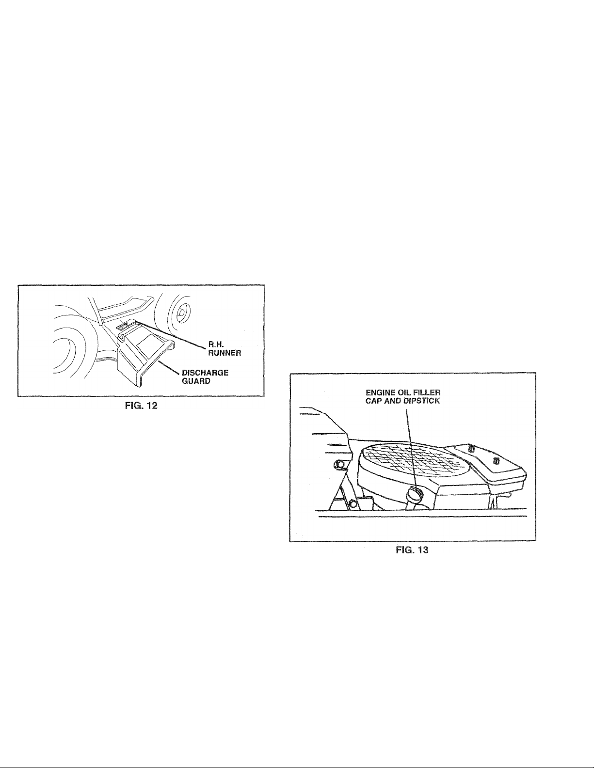
BEFORE STARTING THE ENGINE
CHECK ENGINE OIL LEVEL (See Fig. 13)
• The engine in your unit has been shipped, from the
factory, already filled with summer weight oil.
• Check engine oil with unit on level ground.
• Remove oil fill cap/dipstick and wipe clean, reinsert the
dipstick and screw cap tight, wait for a few seconds,
remove and read oil level. If necessary, add oil until
“FULL” mark on dipstick is reached. Do not overfill.
• For cold weather operation you should change oil for
easier starting (See “OIL VISCOSITY CHART” in the
Customer Responsibilities section of this manual).
• To change engine oil, see the Customer Responsibili
ties section in this manual.
TO OPERATE ON HILLS
CAUTION: Do not drive up or down
A
Choose the slowest speed before starting up or down
hills.
Avoid stopping or changing speed on hills.
If slowing is necessary, move throttle control to slower
position.
if stopping is absolutely necessary, push clutch/brake
pedal quickly to brake position and engage parking
brake.
Move gearshift lever to “NEUTRAL" position.
T0 restart movement, move gearshift lever to 1 st gear.
Be sure you have allowed room for tractor to roll slightly
as you restart movement.
Slowly release parking brake and clutch/brake pedal.
Make all turns slowly.
hills with slopes greater than 15° and
do not drive across any slope.
13
Page 14

OPERATION
ADD GASOUNE
• Fill fuel tank. Use fresh, clean, regular unleaded
gasoline. (Use of leaded gasoline will increase carbon
and lead oxide deposits and reduce valve life).
IMPORTANT: WHEN OPERATING ¡N TEMPERATURES
BELOW 32“F(0°C), USE FRESH, CLEAN WINTER GRADE
GASOLINE TO HELP INSURE GOOD COLD WEATHER
STARTING.
WARNING; Experience indicates that alcohol blended
fuels (called gasohol or using ethanol or methanol) can
attract moisture which leads to separation and formation of
acids during storage. Acidic gas can damage the fuel
system of an engine while in storage. To avoid engine
probiems, the fuel system should be emptied before stor
age of 30 days or longer. Drain the gas tank, start the
engine and let it run until the fuel lines and carburetor are
empty. Use fresh fuel next season. See Storage Instruc
tions for additional information. Never use engine or
carburetor cleaner products in the fuel tank or permanent
damage may occur.
CA'JTION: Fil! to bottc-m of gas tank
filler neck. Donctoverfili. Wipecffany
A
spilied oil or fue!. Do not stere, spili or
use gasciirse near an open tìanie.
TO START ENGINE (See Fig. 11)
When starting engine for the first time or if engine has
run out of fuel, it will take extra cranking time to move
fuel from the tank to the engine.
• Depress the clutch/brake pedal and set the parking
brake,
• Place gearshift lever in “NEUTRAL” position.
® Move attachment clutch to “DISENGAGED” position.
® Pull choke control out to “CHOKE” position for cold
engine start. For warm engine start do not use choke
control.
® Move throttle control to midway between “FAST” and
“SLOW” positions.
® Turn ignition key clockwise to “START” position and
release key as soon as engine starts. Do not run
starter continuously for more than fifteen seconds
per minute, if engine does not start after several
attempts, move throttle control to “FAST" position,
wait a few minutes and try again.
• When engine starts, slowly push choke control in.
® Move throttle control to “FAST” position.
® Allow engine to warm up for a few minutes before
engaging clutch/brake pedal or attachment clutch
switch.
NOTE: If at a high altitude (above 3000 feet) or in cold
temperatures (below 32° 'F), the carburetor fuel mixture
may need to be adjusted for best engine performance.
See ‘TO ADJUST CARBURETOR” in the Service and
Adjustments section of this manual.
MOWING TIPS
® Tire chains cannot be used when the mower housing
is attached to tractor.
• Mower should be properly leveled for best mowing
performance. See ‘TO LEVEL MOWER HOUSING”
in the Service and Adjustments section of this
manual.
• Use the runner on the right hand side of mower as
a guide. The blade cuts approximately an inch out
side the runner (See Fig. 12).
« The left hand side of mower should be used for trim
ming.
® Drive so that clippings are discharged onto the area
that has been cut. Have the cut area to the right of
the tractor. This will result in a more even distribu
tion of clippings and more uniform cutting.
• When mowing large areas, start by turning to the
right so that clippings will discharge away from
shrubs, fences, driveways, etc. After one or two
rounds, mow in the opposite direction making left
hand turns until finished (See Fig. 14).
® If grass is extremely tall, it should be mowed twice
to reduce load and possible fire hazard from dried
clippings. Make first cut relatively high; the second
to the desired height.
• Do not mow grass when it is wet. Wei grass will
plug mower and leave undesirable clumps. Allow
grass to dry before mov/ing.
® Always operate engine at full throttle when mowing
to assure better mowing performance and proper
discharge of material. Regulate ground speed by
selecting a tow enough gear to give the mower cut
ting performance as well as the quality of cut de
sired.
• When operating attachments, select a ground speed
that will suit the terrain and give best performance of
the attachment being used.
FIG. 14
A
CAUTION: Before driving the tractor,
instai! mower or remove front mower
suspension bracket and suspension
arms.
14
Page 15

CUSTOMER RESPONSiBILmEfc
MAINTENANCE SCHEDULE
FILL IN DATES
AS YOU COMPLETE
REGULAR SERVICE
Check Brake Operation
Check Tire Pressure
Check for Loose Fasteners
Sharpen/Replace Mower Blades
Lubrication Chart
Check Battery Level/Recharge
Clean Battery and Terminals
Check Transmission Cooling
Adjust Blade Belt(s) Tension
Adjust Motion Drive Beit(s) Tension
Check Engine Oil Level
Change Engine Oil
Clean Air Filter
Clean Air Screen
Inspect Muffler/Spark Arrester
Replace Oil Filter (If equipped)
Clean Engine Cooling Fins
Replace Spark Plug
Replace Air Filter Paper Cartridge
Replace Fuel Filter
1 - Change more often when operating under a heavy load or in high ambient temperatures.
2 - Service more often when operating in dirty or dusty conditions.
✓
✓
✓
✓
✓ ✓
✓ 4
✓
✓
✓
✓
✓
✓
✓
1^2,3
✓ 2
✓ 2
✓
SERVICE DATES
✓
✓
✓ 5
✓ 5
✓
|/,2
✓ 2
✓
✓
✓ 2
✓
3 - If equipped with oil filter, change oil every 50 hours.
4 - Replace blades more often when mowing in sandy soil.
5 - If equipped with adjustable system.
GENERAL RECOMMENDATIONS
The warranty on this tractor does not cover items that have
been subjected to operator abuse or negligence. To
receive full value from the warranty, operator must main
tain tractor as instructed in this manual.
Some adjustments will need to be made periodically to
properly maintain your tractor.
Ail adjustments in the Service and Adjustments section of
this manual should be checked at least once each season.
• Once a year you should replace the spark plug, clean
or replace air filter, and check blades and belts for
wear. A new spark plug and clean air filter assure
proper air-fuel mixture and helpyourengine run better
and last longer.
BEFORE EACH USE
• Check engine oil level.
• Check brake operation.
• Check tire pressure.
• Check for loose fasteners.
LUBRICATION CHART
©SPINDLE ZERK-
(If equipped)
H
© FRONT WHEEL-
BEARING ZERK
©ATTACHMENT
CLUTCH
PIVOT(S)
©SAE 30 OR 10W30 MOTOR OIL API - SG
©GENERAL PURPOSE GREASE
©REFER TO CUSTOMER RESPONSIBILITIES “ENGINE” SECTION
IMPORTANT: DO NOT OIL OR GREASE THE PIVOT POINTS
WHICH HAVE SPECIAL NYLON BEARINGS. VISCOUS LUBRI
CANTS WILL ATTRACT DUST AND DIRT THAT WILL SHORTEN
THE LIFE OF THE SELF-LUBRICATING BEARINGS. IF YOU
FEEL THEY MUST BE LUBRICATED, USE, ONLY A DRY, POWDERED GRAPHITE TYPE LUBRICANT SPARINGLY.
-i-i
n
SPINDLE ZERK©
(If equipped)
«!
I-L
FRONT WHEEL®
ii
BEARING ZERK
GEARSHIFT @
PIVOTS
ENGINE ®
Page 16

CUSTOMER RESPONSIBIL.HES
TRACTOR
Always observe safety rules when performing any mainte
nance.
BRAKE OPERATION
If tractor requires more than six (6) feet stopping distance
at high speed in highest gear, than brake must be adjusted.
(See “TO ADJUST BRAKE” in the Service and Adjust
ments section of this manual).
TIRES
® Maintain proper air pressure in all tires (See “PROD
UCT SPECIFICATIONS” on page 3 of this manual).
® Keep tires free of gasoline, oil, or insect control chemi
cals which can harm rubber.
® Avoid stumps, stones, deep ruts, sharp objects and
other hazards that may cause tire damage.
BLADE CARE
For best results mower blades must be kept sharp,
place bent or damaged blades.
BLADE REMOVAL (See Fig. 15)
® Raise mower to highest position to allow access to
blades.
® Remove hex bolt, lock washer and flat washersecuring
blade.
® Install new or resharpened blade with trailing edge up
towards deck as shown.
® Reassemble hex bolt, lock washer and fiat washer in
exact order as shown.
® Tighten bolt securely (30-35 Ft. Lbs. torque).
IMPORTANT: BLADE BOLT IS GRADE 5 HEAT TREATED.
Re-
TO SHARPEN BLADE (See Fig. 16)
Care should be taken to keep the blade balanced. An
unbalanced blade will cause excessive vibration and even
tual damage to mower and engine.
* The blade can be sharpened with a file or on a grinding
wheel. Do not attempt to sharpen v/hile on the mower.
• To check blade balance, drive a nai! into a beam or wail.
Leave about one inch of the straight nai! exposed.
Place center hole of blade over the head of the nail. If
blade is balanced, it should remain in a horizontal
position. If either end of the blade moves downward,
sharpen the heavy end until the blade is balanced.
CENTER
HOLE
FIG. 16
BATTERY (See Fig., 17)
Your tractor has a battery charging system which is suffi
cient for normal use. However, periodic charging of the
battery with an automotive charger will extend it's life.
• Acid solution level in each battery cell should be even
with bottoms of vent wells. Add only distilled or iron free
water if necessary. Do not overfill.
» Keep battery and terminals clean.
• Keep battery bolts tight.
• Keep vent caps tight and small vent holes in caps open.
® Recharge at 6 amperes for 1 hour.
16
Page 17

CUSTOMER RESPONSlBlLrnFS
TO CLEAN BATTERY AND TERMINALS -
Corrosion and dirt on the battery and terminals can cause
the battery to “leak” power.
• Remove terminal guard.
• Disconnect BLACK battery cable first, then RED bat
tery cable and remove battery from tractor.
• Wash battery with solution of four tablespoons of
baking soda to one gallon of water. Be careful not to get
the soda solution into the cells.
• Rinse the battery with plain water and dry.
• Clean terminals and battery cable ends with wire brush
until bright.
• Coat terminals with grease or petroleum jelly.
• Reinstall battery (See “INSTALL BATTERY” in the
Assembly section of this manual).
V-BELTS
Check V-Belts for deterioration and wear after 100 hours
and replace if necessary. The mower blade drive and
motion drive belts are not adjustable. Replace belts if they
begin to slip from wear.
TRANSAXLE COOLING
Keep transaxle free from build-up of dirt and chaff which
can restrict cooling.
TO CHANGE ENGINE OIL (See Fig. 18)
Determine temperature range expected before oil change.
All oil must meet API service classification SG.
• Be sure tractor is on level surface.
• Oil will drain more freely when warm.
• Catch oil in a suitable container.
• Remove oil fill cap/dipstick. Be careful not to allow dirt
to enter the engine when changing oil.
• Remove drain plug.
• After oil has drained completely, replace oil drain plug
and tighten securely.
• Refill engine with oil through oil fill dipstick tube. Pour
slowly. Do not overfill. For approximate capacity see
“PRODUCT SPECIFICATIONS” on page 3 of this
manual.
• Use gauge on dipstick for checking level. Be sure
dipstick cap is tightened securely for accurate reading.
Keep oil at “FULL” line on dipstick.
ENGINE
LUBRICATION
Only use high quality detergent oil rated with API service
classification SG. Select the oil's SAE viscosity grade
according to your expected operating temperature.
SAE VISCOSITY GRADES
-20"
°F
‘’c -30'’
TEMPERATURE RANGE ANTICIPATED BEFORE NEXT OIL CHANGE
0°
20" -10" 0° 10° 20° 30° 40°
NOTE: Although multi-viscosity oils (5W30, 10W30, etc.)
improve starting in cold weather, these multi-viscosity oils
will result in increased oil consumption when used above
32° F. Check your engine oil level more frequently to avoid
possible engine damage from running low on oil.
Change the oil after the first two hours of operation and
every 25 hours thereafter or at least once a year if the
tractor is not used for 25 hours in one year.
Check the crankcase oil level before starting the engine
and after each eight (8) hours of continuous use. Tighten
oil fill cap/dipstick securely each time you check the oil
level.
30° 32° 40°
60° 80° 100°
CLEAN AIR SCREEN (See Fig. 18)
The air screen must be kept free of dirt and chaff to prevent
engine damage from overheating. Clean with a wire brush
or compressed air to remove dirt and stubborn dried gum
fibers.
CLEAN ENGINE COOLING FINS
(See Fig. 19)
Remove any dust, dirt or oil from engine cooling fins to
prevent engine damage from overheating. Air guide covers
must be removed. Remove side panels and hood (See “TO
REMOVE HOOD AND GRILL ASSEMBLY” in the Service
and Adjustments section of this manual).
Page 18

CUSTOMER RESPONSIBILITIES
AIR FILTER (See Fig. 20)
Your engine will not run properly using a dirty air filter.
Clean the foam pre-cleaner element after every 25 hours of
operation or every season. Service paper cartridge every
100 hours or every season, whichever occurs first.
Service air cleaner more often under dusty conditions.
* Remove knob(s) and cover.
TO SERVICE PRE-CLEANER
• Slide foam pre-cleaner off cartridge.
® Wash it in liquid detergent and water.
® Squeeze it dry in a clean cloth.
® Saturate it in engine oil. Wrap it in clean, absorbent
cloth and squeeze to remove excess oil.
® Reinstall pre-cleaner over cartridge.
® Reinstall cover and secure with knob(s).
TO SERVICE CARTRIDGE
« Remove wing nuts and cartridge plate.
• Remove cartridge and clean by tapping gently on flat
surface.
* Ifverydirty, replace orwash in a nonsudsing detergent
and warm water solution. Rinse thoroughly with water
from inside out until water runs clear. Let cartridge dry
thoroughly before using.
® Reinstall cartridge plate, wing nuts, precleaner, cover
and secure with knob(s).
IMPORTANT: PETROLEUM SOLVENTS, SUCH AS
KEROSENE, ARE NOT TO BE USED TO CLEAN THE
CARTRIDGE. THEY MAY CAUSE DETERIORATION OF
THE CARTRIDGE. DO NOT OIL CARTRIDGE. DO NOT
USE PRESSURIZED AIR TO CLEAN OR DRY
CARTRIDGE.
MUFFLER
Inspect and replace corroded muffler and spark arrester (if
equipped) as it could create a fire hazard and/or damage.
SPARK PLUGS
Replace spark plugs at the beginning of each mowing
season or after every 100 hours of operation, whichever
comes first. Spark plug type and gap setting are shown in
“PRODUCT SPECIFICATIONS" on page 3 of this manual.
IN-LINE FUEL FILTER (See Fig. 21)
The fuel filter should be replaced once each season. If fuel
filter becomes clogged, obstructing fuel flow to carburetor,
replacement is required.
• With engine cool, remove filter and plug fuel line
sections.
» Place new fuel filter in position in fuel line with arrow
pointing towards carburetor.
• Be sure there are no fuel line leaks and clamps are
properly positioned.
® Immediately wipe up any spilled gasoline.
COVER
WING NUT
FOAM
PRE-CLEANER
AIR SCREEN
FIG. 20
KNOB
CARTRIDGE
PLATE
CARTRIDGE
CLEANING
• Clean engine, battery, seat, finish, etc. of all foreign
matter.
• Keep finished surfaces and wheels free of all gasoline,
oil, etc.
• Protect painted surfaces with automotive type wax.
We do not recommend using a garden hose to clean your
tractor unless the electrical system, muffler, air filter and
carburetor are covered to keep water out. Water in engine
can result in a shortened engine life.
18
Page 19

SERVICE AND ADJUSTMENTS
CAUTION: BEFORE PERFORMING ANY SERVICE OR ADJUSTMENTS:
Depress clutch/brake pedal fully and set parking brake.
Place gearshift lever in “NEUTRAL” position.
Place attachment clutch in “DISENGAGED” position.
A
Turn ignition key “OFF” and remove key.
Make sure the blades and all moving parts have completely stopped.
Disconnect spark plug wire from spark plug and place wire where it cannot come in contact with
plug.
TRACTOR
TO REMOVE MOWER (See Fig. 22)
Mower will be easier to remove from the right side of tractor.
• Remove mower drive belt from electric clutch pulley
only (See ‘TO REPLACE MOWER DRIVE BELT”
through step removing belt from electric clutch pulley).
• Pull retainer springs out of rear suspension trunnions.
Remove rear suspension trunnions from lift brackets.
• Pull retainer springs from front hinge pins.
• Remove hinge pins attaching parallel linkto mower and
front axle.
• Raise lift lever to raise suspension arms. Slide mower
out from under tractor.
IMPORTANT: IFANATTACHMENTOTHERTHANTHEMOWER
DECK IS TO BE MOUNTED ON THE TRACTOR, REMOVE THE
LH. AND R.H. SUSPENSION ARMS AND THE FRONT
SUSPENSION BRACKET.
TO LEVEL MOWER HOUSING
Adjust the mower while tractor is parked on level ground or
driveway. Make sure tires are properly inflated (See
“PRODUCT SPECIFICATIONS” on page 3). If tires are
over or underinflated, you will not properly adjust your
mower.
SIDE-TO-SIDE ADJUSTMENT (See Figs. 23 and 24)
• Raise attachment lift lever to its highest position.
• Measure height from bottom deck curl to ground level at
front corners of mower. Distance “A” should be the
same.
• If distance “A” needs to be changed, snap out access
hole cover on left side of tractor above footrest.
• To raise left side of mower, loosen nut “B” and tighten
nut “C”.
• To lower left side of mower, loosen nut “C” and tighten
nut “B”.
• When distance “A” is equal, securely tighten nuts “B”
and “C”.
• Replace access hole cover.
TO INSTALL MOWER
See “INSTALL MOWER” in the Assembly section of this
manual.
19
Page 20

SERVICE AND ADJUSTMENTS
FRONT-TO-BACK ADJUSTMENT (See Figs. 25 and 26)
To obtain the best cutting results, the mower housing should
be adjusted so the back is approximately 7/8" to 1-1/8"
higher than the front when the mower is in height adjustment
position.
Measure distance “D” from ground line to bottom of deck
curl at centerline outside of mandrels.
• To raise rear of mower, loosen nut “E” on both rear
suspension arms. Screw both nuts “F” on both rear
suspension arms an equal number of turns.
• When distance “D” is 7/8" to 1-1/8" higher at rear than
front, retighten nuts “E”.
• Recheck side-to-side adjustment.
IMPORTANT: WHEN ADJUSTING REAR SUSPENSION ARMS,
ALWAYS ADJUST BOTH EQUALLY SO MOWER WILL STAY
LEVEL SIDE-TO-SIDE.
TO ADJUST ATTACHMENT CLUTCH
(See Fig. 27)
The electric clutch should provide years of service. The
clutch has a built-in brake that stops the pulley within 5
seconds. Eventually, the internal brake will wear so the
mower blades will not stop as recommended. Adjustments
should be made by authorized service technician.
* Make sure attachment clutch and ignition switches are
in the “OFF” position.
• Adjust the three nylon locknuts until the space between
clutch plate and rotor measures .012 inches at all three
slot locations cut in side of brake plate.
NOTE: After installing a new electric clutch, run tractor at
full throttle, and engage and disengage electric clutch 10
cycles to wear in clutch plate.
ROTOR
CLUTCH PLATE
FIG. 27
20
Page 21

SERVICE AND ADJUSTMENTS
TO REPLACE MOWER DRIVE BELT
(See Figs. 28 and 29)
Park the tractor on level surface. Engage parking brake.
BELT REMOVAL -
• Place attachment clutch in “DISENGAGED” position.
• Turn height adjustment knob to lowest setting.
• Move attachment lift lever forward to lower mowerto its
lowest position.
• Roll belt off electric clutch pulley.
• Pull belt off mower pulley and both idler pulleys.
BELT INSTALLATION -
• Place belt around mower pulley and both idler pulleys.
• Roll belt over electric clutch pulley.
• Make sure belt is in all pulley grooves and inside all belt
guides.
TO ADJUST BRAKE (See Fig. 30)
Your tractor is equipped with an adjustable brake system
which is mounted on the right side of the transaxle.
If tractor requires more than six (6) feet stopping distance
at high speed in highest gear, then brake must be adjusted.
• Depressclutch/brake pedal and engage parking brake.
• Measure distance between brake operating arm and
nut “A” on brake rod.
• If distance is other than 1-1/2", disengage parking
brake, loosen jam nut and turn nut “A” until distance
becomes 1-1/2". Retighten jam nut against nut “A”.
• Engage parking brake and recheck distance.
• Road testtractorfor proper stopping distance as stated
above. Readjust if necessary. If stopping distance is
still greater than six (6) feet in highest gear, further
maintenance is necessary. Contact your nearest au
thorized service center.
FIG. 30
TO REPLACE MOWER BLADE DRIVE BELT
(See Fig. 31)
• Remove mower (See “TO REMOVE MOWER” in this
section of this manual).
• Remove mowerdrive belt (See “TO REPLACE MOWER
DRIVE BELT” in this section of this manual).
• Pull mower blade drive belt towards rear of mower at
tensioning pulley. Place a block between tensioning
pulley and mower lift bracket. Roll belt off tensioning
pulley.
• Roll belt off all other pulleys.
• Slide belt from under spring.
• To install belt, reverse above procedure. Make sure
F!G. 29
21
FIG. 31
Page 22

SERVICE AND ADJUSTMENTS
TO REPLACE MOTION DRIVE BELT
(See Fig. 32)
Park the tractor on level surface. Engage parking brake.
For assistance, there is a belt installation guide decal on
bottom side of ¡eft footrest.
Remove mower (See “TO REMOVE MOWER” in this
section of this manual.)
Disconnect clutch wire harness.
Remove clutch locator.
Remove upper belt keeper.
Remove belt from stationary idler and clutching idler.
Pull belt slack toward rear of tractor. Remove belt
upwards from transaxle pulley by deflecting belt keep
ers.
® Pull belt toward front of tractor and remove downwards
from around electric clutch.
* Install new belt by reversing above procedure.
IMPORTANT: MAKE SURE UPPER BELT KEEPER IS
POSITIONED PROPERLY BETWEEN LOCATOR TABS
AND ELECTRIC CLUTCH WIRE CONNECTION IS
SECURE.
TRANSAXLE SHIFTER LINKAGE AND AD
JUSTMENT (See Figs. 33 and 34)
The transaxle should be in neutral when the gearshift lever
is in the neutral (lock gate) position. The adjustment is
preset at the factory: however, if adjustment is needed,
proceed as follows:
* Make sure transaxle is in neutral.
® Loosen two locknuts on tie rod.
» Turn center rod until gearshift lever fails into neutral
lock gate on fender console.
• Tighten locknuts securely.
TO ADJUST STEERING WHEEL ALIGNMENT
If steering wheel crossbars are not horizontal (left to right)
when wheels are positioned straight forward, remove
steering wheel and reassemble per instructions in the
Assembly section of this manual.
FRONT WHEEL TOE-IN/CAMBER
The front wheel toe-in and camber are not adjustable on
your tractor. If damage has occurred to affect the front
wheel toe-in or camber, contact your nearest authorized
service center.
22
Page 23

SERVICE AND ADJUSTMENTS
TO REMOVE WHEEL FOR REPAIRS
(See Fig. 35)
• Block up axle securely.
• Remove axle cover, retaining ring and washers to allow
wheel removal (rear wheel contains a square key - Do
not lose).
• Repair tire and reassemble.
• On rear wheels only: align grooves in rear wheel hub
and axle. Insert square key.
• Replace washers and snap retaining ring securely in
axle groove.
• Replace axle cover.
AXLE COVER
FIG. 35
SQUARE KEY
(REAR WHEELS ONLY)
TO START ENGINE WITH A WEAK BATTERY (See Figs. 36 and 37)
CAUTION: Lead-acid batteries generate
explosive gases. Keep sparks, flame and
smoking materials away from batteries.
A
If your battery is too weak to start the engine, it should be
recharged. If “jumper cables” are used for emergency
starting, follow this procedure:
IMPORTANT; YOUR TRACTOR IS EQUIPPED WITH A 12
VOLT NEGATIVE GROUNDED SYSTEM. THE OTHER
VEHICLE MUST ALSO BE A 12 VOLT NEGATIVE
GROUNDED SYSTEM. DO NOT USE YOUR TRACTOR
BATTERY TO START OTHER VEHICLES.
TO ATTACH JUMPER CABLES -
• Connect each end of the RED cable to the POSITIVE
(-1-) terminal of each battery, taking care not to short
against chassis.
• Connect one end of the BLACK cable to the NEGA
TIVE (-) terminal of fully charged battery.
• Connect the other end of the BLACK cable to a panel
bolt on the left side of the chasis, away from the fuel
tank and battery.
TO REMOVE CABLES, REVERSE ORDER -
• BLACK cable first from chassis and then from the fully
charged battery.
• RED cable last from both batteries.
Always wear eye protection when around
batteries.
TO REPLACE FUSE
Replace with 30 amp automotive-type plug-in fuse. The
fuse holder is located behind the dash.
TO REPLACE HEADLIGHT BULB
• Raise hood.
• Pull bulb holder out of the hole in the backside of the
grill.
• Replace bulb in holder and push bulb holder securely
back into the hole in the backside of the grill.
• Close hood.
INTERLOCKS AND RELAYS
Loose or damaged wiring may cause your tractor to run
poorly, stop running, or prevent it from starting.
• Check wiring. See the electrical wiring diagram in the
Repair Parts section of this manual.
FIG. 37
23
Page 24

SERVICE AND ADJUSTMENTS
TO REMOVE HOOD AND GRILL ASSEMBLY
(See Fig. 38)
® Lift hood. Disconnect headlight wire connection.
® Remove wing nuts on inside of side panels.
® Pivot hood and side panel forward and lift off tractor.
* To replace, reverse above procedure.
With engine not running, move choke control (located
on dash panel) to full “CHOKE” position.
Remove air cleaner cover, filter and spitback plate to
expose carburetor choke (see “AIR FILTER” in Cus
tomer Responsibilities section).
Choke should be closed. If it is not, loosen casing
clamp screw and move choke cable until choke is
completely closed. Tighten casing clamp screw se
curely.
Reassemble air cleaner.
ENGINE
TO ADJUST THROTTLE CONTROL CABLE
(See Fig. 39)
The throttle control has been preset at the factory and
adjustment should not be necessary. Check adjustment as
described below before loosening cable, if adjustment is
necessary, proceed as follows:
® With engine not running, move throttle control lever to
“FAST” position.
® Check that swivel is against side of quarter circle, ¡fit
is not, loosen cable clamp screw and pull cable back
until swivel is against quarter circle. Tighten cable
clamp screw securely.
TO ADJUST CHOKE CONTROL (See Fig. 40)
The choke control has been preset at the factory and
adjustment should not be necessary. Check adjustment as
described below before loosening cable. If adjustment is
necessary, proceed as follows:
TO ADJUST CARBURETOR
The carburetor has been present at the factory and adjust
ment should not be necessary. However, minor adjust
ment may be required to compensate for differences in fuel,
temperature, altitude or load. If the carburetor does not
need adjustment, see the engine manual packed with your
tractor.
High speed stop is factory adjusted. Do not adjust-damage
may result.
IMPORTANT; NEVER TAMPER WITH THE ENGINE
GOVERNOR, WHICH IS FACTORY SET FOR PROPER
ENGINESPEED. OVERSPEEDING THE ENGINE ABOVE
THE FACTORY HIGH SPEED SETTING CAN BE
DANGEROUS. IF YOU THINKTHE ENGINE-GOVERNED
HIGH SPEED NEEDS ADJUSTING, CONTACT YOUR
NEAREST AUTHORIZED SERVICE CENTER, WHICH HAS
PROPER EQUIPMENT AND EXPERIENCE TO MAKE ANY
NECESSARY ADJUSTMENTS.
24
Page 25

STORAGE
Immediately prepare your tractor for storage at the end of
the season or if the tractor will not be used for 30 days or
more.
CAUTION: Never store the tractor with
gasoline in the tank inside a building
where fumes may reach an open flame
A
or spark. Allow the engine to cool
before storing in any enclosure.
TRACTOR
Remove mower from tractor for winter storage. When
mower is to be stored for a period of time, clean it thor
oughly, remove all dirt, grease, leaves, etc. Store in a
clean, dry area.
• Clean entire tractor (See “CLEANING” in the Customer
Responsibilities section of this manual).
• inspect and replace belts, if necessary (See belt re
placement instructions in the Service and Adjustments
section of this manual).
• Lubricate as shown in the Customer Responsibilities
section of this manual.
• Be sure that ail nuts, bolts and screws are securely
fastened. Inspect moving parts for damage, breakage
and wear. Replace if necessary.
• Touch up all rusted or chipped paint surfaces; sand
lightly before painting.
BATTERY
• Fully charge the battery for storage.
• After a period of time in storage, battery may require
recharging.
• To help prevent corrosion and power leakage during
long periods of storage, battery cables should be
disconnected and battery cleaned thoroughly (see “TO
CLEAN BATTERY AND TERMINALS” in the Cus
tomer Responsibilities section of this manual).
• After cleaning, leave cables disconnected and place
cables where they cannot come in contact with battery
terminals.
• Be sure battery drain tube is securely attached.
• If battery is removed from tractor for storage, do not
store battery directly on concrete or damp surfaces.
ENGINE
FUEL SYSTEM
IMPORTANT. IT IS IMPORTANT TO PREVENT GUM
DEPOSITS FROM FORMING IN ESSENTIAL FUEL
SYSTEM PARTS SUCH AS CARBURETOR, FUEL FILTER,
FUEL HOSE, OR TANK DURING STORAGE. ALSO,
EXPERIENCE INDICATES THAT ALCOHOL BLENDED
FUELS (CALLED GASOHOL OR USING ETHANOL OR
METHANOL) CAN ATTRACT MOISTURE WHICH LEADS
TO SEPARATION AND FORMATION OF ACIDS DURING
STORAGE, ACIDIC GAS CAN DAMAGE THE FUEL
SYSTEM OF AN ENGINE WHILE IN STORAGE.
• Drain the fuel tank.
• Start the engine and let it run until the fuel lines and
carburetor are empty.
• Never use engine orcarburetor cleaner products in the
fuel tank or permanent damage may occur.
• Use fresh fuel next season.
NOTE: Fuel stabilizer is an acceptable alternative in
minimizing the formation of fuel gum deposits during stor
age. Add stabilizer to gasoline in fuel tank or storage
container. Always follow the mix ratio found on stabilizer
container. Run engine at least 10 minutes after adding
stabilizer to allow the stabilizer to reach the carburetor. Do
not drain the gas tank and carburetor if using fuel stabilizer.
ENGINE OIL
Drain oil (with engine warm) and replace with clean engine
oil. (See “ENGINE” in the Customer Responsibilities
section of this manual).
CYLINDERS
Remove spark plug(s).
Pour one ounce of oil through spark plug hole(s) into
cylinder(s).
Turn ignition key to “ST ART” position fora few seconds
to distribute oil.
Replace with new spark plug(s).
OTHER
Do not store gasoline from one season to another.
Replace your gasoline can if your can starts to rust.
Rust and/or dirt in your gasoline will cause problems.
If possible, store your tractor indoors and cover it to
give protection from dust and dirt.
Cover your tractor with a suitable protective cover that
does not retain moisture. Do not use plastic. Plastic
cannot breathe which allows condensation to form and
will cause your tractor to rust.
IMPORTANT: NEVER COVER TRACTOR WHILE ENGINE
AND EXHAUST AREAS ARE STILL WARM.
25
Page 26

TROUBLESHOOTING POINTS
PROBLEM
Will not start 1. Out of fuel.
Hard to start 1. Dirty air filter.
Engine will not turn over
CAUSE
2. Engine not “CHOKED” properly.
3. Engine flooded.
4. Bad spark plug.
5. Dirty air filter.
6. Dirty fuel filter.
7. Water in fuel.
8. Loose or damaged wiring.
9. Carburetor out of adjustment.
10. Engine valves out of adjustment.
2. Bad spark plug.
3. Weak or dead battery.
4. Dirty fuel filter.
5. Stale or dirty fuel.
6. Loose or damaged wiring.
7. Carburetor out of adjustment.
8. Engine valves out of adjustment.
1. Clutch/brake pedal not depressed.
2. Attachment clutch is engaged.
3. Weak or dead battery.
4. Blown fuse.
5. Corroded battery terminals.
6. Loose or damaged wiring.
7. Fauity ignition switch.
8. Faulty solenoid or starter.
9. Faulty operator presence switch(es).
CORRECTION
1. Fill fuel tank.
2. See ‘TO START ENGINE” in Operation section.
3. Wait several minutes before attempting to start.
4. Replace spark plug.
5. Clean/replace air filter.
6. Replace fuel filter.
7. Drain fuel tank and carburetor, refill tank with fresh
gasoline and replace fuel filter.
8. Check all wiring.
9. Contact an authorized service center/department.
10. Contact an authorized service center/department.
1. Clean/replace air filter.
2. Replace spark plug.
3. Recharge or replace battery.
4. Replace fuel filter.
5. Drain fuel tank and refill with fresh gasoline.
6. Check all wiring.
7. Contact an authorized service center/department.
8. Contact an authorized service center/department.
1. Depress clutch/brake pedal.
2. Disengage attachment clutch.
3. Recharge or replace battery.
4. Replace fuse.
5. Clean battery terminals.
6. Check all wiring.
7. Check/repiace ignition switch.
8. Check/repiace solenoid or starter.
9. Contact an authorized service center/department.
Engine clicks but will not
start 2. Corroded battery terminals.
Loss of power
Excessive vibration
1. Weak or dead battery.
3. Loose or damaged wiring.
4. Fauity solenoid or starter.
1. Cutting too much grass/too fast.
2. Throttle in “CHOKE” position.
3. Build-up of grass, leaves and trash under mower.
4. Dirty air filter.
5. Low oil level/dirty oil.
6. Faulty spark plug.
7. Dirty fuel filter.
8. Stale or dirty fuel.
9. Water in fuel.
10. Spark plug wire loose.
11. Dirty engine air screen/fins.
12. Dirty/clogged muffler.
13. Loose or damaged wiring.
14. Carburetor out of adjustment.
15. Engine valves out of adjustment.
1. Worn, bent or loose blade.
2. Bent blade mandrel.
3. Loose/damaged part(s).
1. Recharge or replace battery.
2. Clean battery terminals.
3. Check all wiring.
4. Check/repiace solenoid or starter.
1. Set in “Higher Cut” position/reduce speed.
2. Adjust throttle control.
3. Clean underside of mower housing.
4. Clean/replace air filter.
5. Check oil level/change oil.
6. Clean and regap or change spark plug.
7. Replace fuel filter.
8. Drain fuel tank and refill with fresh gasoline.
9. Drain fuel tank and carburetor, refill tank with fresh
gasoline and replace fuel filter.
10. Connect and tighten spark plug wire.
11. Clean engine air screen/fins.
12. Clean/replace muffler.
13. Check aii wiring.
14. Contact an authorized service center/department.
15. Contact an authorized service center/department.
1. Replace blade. Tighten blade bolt.
2. Replace blade mandrel.
3. Tighten loose part{s). Replace damaged parts.
25
Page 27

TROUBLESHOOTING POINTS
PROBLEM
Engine continues to run
when operator leaves seat
with attachment clutch
engaged
Poor cut - uneven
Mower blades will not
rotate
Poor grass discharge 1. Engine speed too slow.
CAUSE
1. Faulty operator-safety presence control system.
1. Worn, bent or loose blade.
2. Mower deck not level.
3. Buildup of grass, leaves, and trash under mower.
4. Bent blade mandrel.
1. Obstruction in clutch mechanism.
2. Mower drive belt out of adjustment.
3. Worn/damaged mower drive belt.
4. Frozen idler pulley.
5. Frozen blade mandrel.
2. Travel speed too fast.
3. Wet grass.
4. Mower deck not level.
5. Low/uneven tire air pressure.
6. Worn, bent or loose blade.
7. Buildup of grass, leaves and trash under mower.
8. Mower drive belt worn or out of adjustment.
9. Blades improperly installed.
10. Improper blades used.
CORRECTION
1. Check wiring, switches and connections. If not
corrected, contact an authorized service center/
department.
1. Replace blade. Tighten blade bolt.
2. Level mower deck.
3. Clean underside of mower housing.
4. Replace blade mandrel.
1. Remove obstruction.
2. Adjust mower drive belt.
3. Replace mower drive belt.
4. Replace idler pulley.
5. Replace blade mandrel.
1. Place throttle control in “FAST” position.
2. Shift to slower speed.
3. Allow grass to dry before mowing.
4. Level mower deck.
5. Check tires for proper air pressure.
6. Replace/sharpen blade. Tighten blade bolt.
7. Clean underside of mower housing.
8. Replace/adjust mower drive belt.
9. Reinstall blades sharp edge down.
10. Replace with blades listed in this manual.
Headlight(s) not working
(if so equipped)
Battery will not charge 1. Bad battery cell(s).
Engine “backfires”
when turning engine
“OFF”
1. Switch is “OFF”.
2. Bulb(s) burned out.
3. Faulty light switch.
4. Loose or damaged wiring.
5. Blown fuse.
2. Poor cable connections.
3. Faulty regulator (if so equipped).
4. Faulty alternator.
1. Engine throttle control not set at “SLOW”
position for 30 seconds before stopping engine.
1. Turn switch “CN”.
2. Replace bulb(s).
3. Check/replace light switch.
4. Check wiring and connections.
5. Replace fuse.
1. Replace battery.
2. Check/clean all connections.
3. Replace regulator.
4. Replace alternator.
1. Move throttle control to “SLCW” position and allow
to idle for 30 seconds before stopping engine.
27
Page 28

SCHEMATIC
18 HP 44" TRACTOR - - MODEL NUMBER X1844A
RED
o
V WHITE
CLUTCH/BRAKE
TILLER
ATTACHMENT
CONNECTOR
SEAT SWITCH
(NOT OCCUPIED)
BATTERY
FUSE 30 AMP.
(PEDAL UP)
^cy
T
T“
K)
GROUNDING
CONNECTOR
o
a
(DISENGAGED)
PTO
BLACK
ELECTRIC CLUTCH
RED
BUCK
OPERATOR PRESENCE
STARTER
85 86 I
87,
30'
o
87A
RELAY
BUCK
BUCK
BUCK
1
RELAY
IGNITION SWITCH
POSITION CIRCUIT
OFF
ON B + L
START B + S
M + G
BLACK
IGNITION
CHARGING SYSTEM OUTPUT
' 6 AMP DC POS. @ 3600 RPM
30 VOLTS AC MIN. @ 3600 RPM
^{CHARGING SYSTEM DISCONNECTED)
-c
_ I
HEADLIGHT
SWITCH (OFF)
REMOVABLE
CONNECTIONS
NON-REMOVABLE
CONNECTIONS
WIRING INSULATED CLIPS
NOTE: IF WIRING INSULATED
CLIPS WERE REMOVED FOR
SERVICING OF UNIT, THEY
SHOULD BE REPLACED TO
PROPERLY SECURE YOUR WIRING
UNIT
POSITION
OFF
ON
SPARK
-o
PLUGS
PTO SWITCH
CIRCUIT
B + E, C + D
B + A, C + F
I
28
Page 29
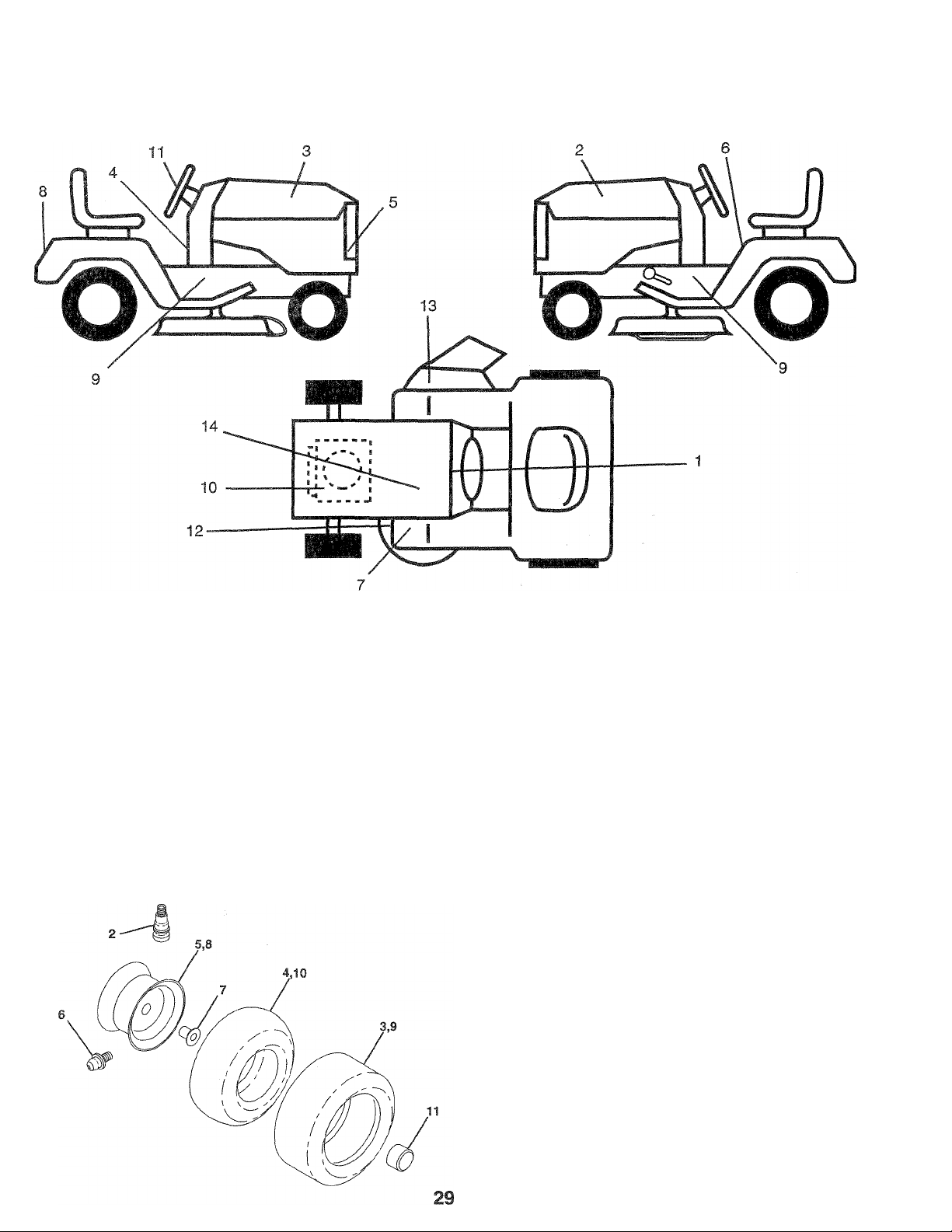
REPAIR PARTS
18 HP 44” TRACTOR - - MODEL NUMBER X1844A
DECALS
KEY
NO.
10
PART
NO.
1
138956
2
128018
3
128015
4
138956 Decal Dash Inst.
5
128007
6
133795 Decal, Caution
7
101892X
8
128006
9
134545 Decal Chassis
135426 Decal, Engine B&S 18 HP
DESCRIPTION
Decal, Operating Instructions
Decal, Hood, LH
Decal, Hood, RH
Decal Grille
Decal, Clutch/Brake
Decal Fender
WHEELS AND TIRES
KEY PART
NO. NO.
11 128009
12 136834 Decal V-Belt Schematic
13 137259
14 121549X Decal Caution
-- 138311 Decal, Handle Lift
-- 139700 Manual, Owner's
Available accessories (not included with tractor):
SB10 40" Snow Blower
LC02 42" Snow Blade
TA321 55 lb. Wheel Wts. (ea.)
TX11
LA028
TS15
TR69
KEY PART
NO. NO.
1 59192
2 65139
3 106222X
4 59904
5 106732X475
6 278H
7 9040H
8 124074X475
9 124106X
10 7154J
11 104757X
DESCRIPTION
Decal, Steering Wheel Insert
Decal Warning
Sleeve Hitch
Tire Chains 23 x 8.5 X 12
P.T.O. Tiller
48" Dozer Blade
DESCRIPTION
Valve Cap, Tire
Stem, Valve
Tire, Front
Tube, Front (Service Item Only)
Rim Assembly, Front
Fitting, Grease (Front Wheel Only)
Bearing, Flange (Front Wheel Only)
Rim Assembly, Rear
Tire, Rear
Tube, Rear (Service Item Only)
Cap, Axle, Black 1.50 x 1.00
NOTE: All component dimensions given in U.S. inches.
1 inch = 25.4 mm
Page 30

REPAIR PARTS
18 HP 44” TRACTOR - - MODEL NUMBER X1844A
ELECTRICAL
B
30
Page 31

REPAIR PARTS
18 HP 44" TRACTOR - - MODEL NUMBER X1844A
ELECTRICAL
KEY
NO.
10 7697J Tube, Battery Tray
11 7192J Cable Tie
12 11150400
13 4206J
14 4406R
15
16
17
18
19
20
21
22
23 4207J
24 10090400
25
26
27
28
29 73640400 Nut, Keps, Hex 1/4-20
30
31
32 11050400
33
34 9433R
35
36 10101000
37 73911000 Nut
38
39
40 235R
41 4022J
42
43
44 73350400 Nut, Keps #10-32 UNF
45
46
47
48
49
50
PART
NO.
123198X Wingnut 1/4-20
1
19091016
2
102476X
3
4 72240460
121537X Battery
5
6 7603J
138803 Harness, Ignition
7
136849 Harness, Light Socket
8
9 7662J
12421IX Nut, Ignition
122147X Key, Molded
138406
110712X
73680400 Nut, Hex 1/4-20
109748X Relay
4799J
131563 Cover, Terminal (For Solenoid)
109596X Clamp, Hose
10040400 Washer, Lock 1/4
126016X Switch, PTO
71110408 Bolt, Hex 1/4-20 X 1/2 Gr. 5
74760412 Bolt, Hex 1/4-20x3/4
73220400 Nut, Hex 1/4-20
108824X Fuse, 30 AMP
131708
19070818 Washer 7/32 x 1/2 x 18 Ga.
102501X
104445X Switch, Interlock, Clutch
121264X Cap, Battery
123620X Bezel, Ignition
121305X
17021008 Screw, Hex, Tapping
135665
19171216 Washer 17/32 x 3/4 x 16 Ga.
19121618 Washer 3/4 x 1 x 18 Ga.
DESCRIPTION
Washer 9/32 x 5/8 x 16 Ga.
Guard, Terminal
Bolt, Carriage 1/4-20 x 7-1/2
Tray, Battery
Bulb, Light
Washer, Lock Internal Tooth 1/4
Cable, Battery (Battery to Solenoid)
Switch, Ignition
Solenoid
Switch, Light
Cable, Battery (Solenoid to Starter)
Cable, Battery (Battery to Ground)
Washer, Lock, External Tooth 1/4
Washer, Lock, External Tooth 1/4
Ammeter
Bracket, Ammeter
Washer, Lock #10
Loop, Wire
Clip, insulated
Nut, Hex
Switch, Plunger
#10-24 UNCx 1/2 Type T
Diode Assembly
NOTE:
Ail component dimensions given in U.S. inches.
1 inch = 25.4 mm
31
Page 32

REPAIR PARTS
18 HP 44" TRACTOR - - MODEL NUMBER X1844A
CHASSIS AND ENCLOSURES
A B D E FGHJLMN qPQR STUVWX AABB
©54
C» 66 76
Ii|i65 ©86
4 ^
in
©^2 015©85
37 174 I 71 ©54 41
, ©53
] 51 ® 7 ' 70
69
ns
©
73
0 0
57 y 82 i
44
© 'W
^ O
I 87 I
80
579
ne ni
a
!93
I 94
Page 33

REPAIR PARTS
18 HP 44" TRACTOR - - MODEL NUMBER X1844A
CHASSIS AND ENCLOSURES
KEY PART
NO. NO.
1
127429
2 131451
3 126656X
4 105529X
6 73680500
7
73680600
123784X475
8
120068X Knob, Seat
10
11 17490612
12 19131312
13 74760612
14 10551IX Strap, Fender
19171912 Washer 11/32 x 13/16 x 12 Gauge
15
121246X
18
19 124181X
20 105531X Nut, Push
21
137113
22 124238X
127334X Tank, Fuel
23
24
123549X Cap, Fuel
123487X Clamp, Hose
25
26 7834R Line, Fuel
27 106082X
28 127166X
29 123785X
30 138644
31 121794X
32 138643 Bushing, Snap
35 105465X475
36 105464X475 Footrest, RH
37 72110606 Bolt, Carriage 3/8-16 x 3/4
38 133671
40 3645J Bushing
41 123198X Wing Nut, Plastic, Locking 1/4-20
42 2751R
43 110436X Grommet, Split
44 17490512 Screw, Thd. Roll. 5/16-18 x 3/4
45 105419X475 Strap, Grille
46
73510400
48
73731000
49
19070818
50
132635X475 Hood
51 7206J
52 74981020 Screw, Machine #10-24 x 1-1/4
53
73220400
54
19091216
DESCRIPTION
Seat
Pan, Seat
Bracket, Pivot, Seat
Bolt, Shoulder 5/16-18
Nut, Crownlock 5/16-18
Nut, Crownlock 3/8-16
Fender
Screw. Hex Washer Head, Thd.
Roll. 3/8-16x3/4
Washer 13/32 x 13/16x12 Gauge
Bolt, Hex 3/8-16x3/4
Bracket, Switch, Seat
Spring, Compression
Bracket, Fender
Cap, Spring, Seat
Pad, Spacer
Chassis Assembly
Drawbar
Panel, Dash, LH
Cover, Access
Footrest, LH
Pad, Footrest
Clip, Insulated
Nut, Keps 1/4-20
Nut, Keps #10-24
Washer 7/32 x 1/2 x 18 Gauge
Spacer, Split
Nut, Hex, Fin. 1/4-20
Washer 9/32 x 3/4 x 16 Gauge
KEY PART
NO.
NO.
131681
55
73680400
56
123481X
57
121248X
58
121249X
59
123740X
60
132639X475
61
132638X475
62
104618X
63
106784X
64
65 2029J
10071000
66
106395X
67
124392X417 Bezel, Headlight
68
74191008
69
104755X
70
17211010
71
72 109808X
74640806
73
74760612
74
139227
75
10100800
76
123825X
77
78 4171R
73951000
79
74641008
80
123976X
81
82 127018X
72050411
83
121251X
84
19131614
85
19060718
86
17490608
87
17490508
88
109227X
89
135029
90
17490616
91
92 19131616
72110608
93
94 73680600
132644
95
17490412
96
19091016
97
19131210
98
NOTE: All component dimensions given in U.S. inches
1 inch = 25.4 mm
DESCRIPTION
Grille
Nut, Crownlock 1/4-20
Bolt, Shoulder 1/4-20
Bushing, Snap
Spacer, Split
Spring, Compression
Panel, Side, RH
Panel, Side, LH
Strap Assembly, Hinge, Front
Strap Assembly, Hinge, Rear
Nut, Welded #10-24
Washer, Lock
Lens, Headlight, Bar
Screw, Machine #10-24 x 1/2
"J" Fastener
Screw, Hex Washer Head, Tapping
Latch, Chute
Screw #8 X 3/8
Bolt, Hex 3/8-16x3/4
Stem, Fuel Tank
Washer, Lock #8
Console, Shifter
Clip, Insulated
Nut, Keps #10-24
Screw, Slotted Pan Head
#10-24 X 1/4
Nut, Hex, Flange, Large
Bolt, Shoulder
Bolt, Carriage 1/4-20 x 1-3/8
Strip, Foam
Washer 13/32 x 1 x 14 Gauge
Washer 3/16x7/16x18 Gauge
Screw Thdrol 3/8-16 x 1/2
Screw Thdrol 5/16-18x1/2
Pad Spacer
Guard Muffler
Screw Thdrol 3/8-16 x 1
Washer 13/32x 1 x 16 Ga.
Bolt Rdhd Sqnk 3/8-16 x 1 Gr. 5
Nut, Crownlock 3/8-16
Bracket Grille
Screw Hexwash
Washer 9/32 x 5/8 x 16 Ga.
Washer 13/32 x 3/4 x 10 Ga.
33
Page 34

REPAIR PARTS
18 HP 44" TRACTOR - - MODEL NUMBER X1844A
DRIVE
3J ”0
102
P is'* J,
F
OPTIONAL EQUIPMENT -
SPARK ARRESTER KIT
7
104
A BDFGHJ KLMNQ
^ 28 O © 0> © ©
j 26 124
g
©27 ©27
©28 ©6
51
fci«., ‘OJ 'flj’ Hon lii«
52 |75 I
87
a I
©116 ©51 028 ©94
©51
101
87 124 112
34
11s
Page 35

REPAIR PARTS
18 HP 44” TRACTOR - - MODEL NUMBER X1844A
DRIVE
KEY PART
NO. NO.
1 121327X
2 12000004
3 2228M
4 138788
5 72140506
6 19111214
7 71208
8
9 126197X
10 100229L
12 17490512
13
14 108373X
17 123796X
19 106933X
20 123781X
21 105701X
22 19171216
23 76020416
24 17490612
25 129921
26 74760616
27 19131312
28 73680600
29 8883R
30 122424X
31 1572H
32 19211616
34 123792X
35 137140
36 136715
37 109070X
38 4470J
39 123674X
40 74760644
41 136906
42 10040700
43 71170768
44 123791X
46 123776X
47 120183X
48 71040412
49 19091216
51 73680500
52 74780544
53 123787X
54 123780X
55 123794X
56 76020412
DESCRIPTION
Pulley, Transaxle
Ring, Retainer
Key, Woodruff #9
Transaxle, Peerless, 6 Speed,
Model Number 820-016B
Bolt, Carriage 5/16-18 x 3/4
Washer 11/32 x 3/4 x 14 Ga.
Bushing, Rod, Steering
Engine, B&S, 18 HP,
Mode! No. 422707
Washer 15/32x1-3/4x1/4
Tube, Exhaust
Screw, Hex Wash Head
5/16-18x2-1/2
Plug, Oil Drain
(Order from Engine Manufacturer)
Muffler
V-Beit, Drive
Knob
Rod, Shifter
Washer, Shift Plate
Washer 17/32 x 3/4 x 16 Gauge
Pin, Cotter 1/8x1
Screw, Hex Washer Head, Thd.,
Roll. 3/8-16x3/4
Keeper, Belt, Engine, LH
Bolt, Hex Head 3/8-16 x 1
Washer 13/32 x 13/16 x 12 Gauge
Nut, Crownlock 3/8-16
Cover, Foot Pedal
Shaft, Foot Pedal
Pin, Roll 3/16x1
Washer 21/32 x 1 x 16 Gauge
Keeper, Belt, Transaxle, RH
Clutch, Electric
Retainer, Beit
Keeper, Belt
Spacer
Idler, Flat
Bolt, Hex 3/8-16x2-3/4
Pulley, Engine
Washer, Lock 7/16
Bolt, Hex Head 7/16-20 x 4-1/4
Keeper, Belt, Transaxle, LH
Bracket, Transaxle, RH
Bearing, Nylon
Bolt, Hex Head 1/4-28 x 3/4
Washer 9/32 x 3/4 x 16 Gauge
Nut, Crownlock 5/16-18
Bolt, Hex 5/16-18x2-3/4
Strap, Torque
Bracket, Transaxle, LH
Arm, Shifter
Pin, Cotter 1/8 X 3/4
KEY PART
NO. NO.
57 133261
123786X
58
59 71673
60 126909X
61 19131316
123800X
62
127783
65
123789X
66
67 123205X
68 74760624
DESCRIPTION
Rod, Parking Brake
Rod, Brake
Cap, Plunger
Spring, Brake Rod
Washer 13/32 x 13/16 x 16 Gauge
Washer 1-1/32 x 1-5/8 x 16 Gauge
Pulley, Idler
Arm, Idler
Retainer, Belt
Bolt, Hex Head 3/8-16 x 1-1/2
69 110812X Washer, Hardened
70 12000039
71 105709X
72 10571 OX
73530400
73
Ring, Clip
Spring, Return, Clutch
Link, Clutch
Nut 1/4-28
74 132747 Control, Throttle
75 17720410
Screw, Hex Head, Thread Cutting
1/4-20x5/8
108097X
81
82 108236X
83 12000053
85 9396E
Spacer, Split
Bracket, Switch
E-Ring
Key, Square 1/4 x 2
87 17490624 Screw, Hex Washer Head, Thd.,
Roll. 3/8-16x1-1/2
88 19212016
89 74760612
90 105706X
91 12000008
92 123772X
123782X
93
94
11050600
Washer 21/32 x 1-1/4 x 16 Gauge
Bolt, Hex Head 3/8-16 x 3/4
Bearing
Ring, Klip
Shaft Assembly, Shifter
Spring, Torsion
Washer, Lock, External Tooth 3/8
97 73800600 Locknut 3/8-16
137141 Retainer Assembly, Clutch
98
101 74760540
Screw, Hex Washer Head, Thd.,
Roll. 5/16-18x2-1/2
102 2751R Clip, Fuel Line
103 123793X
Rod, Tie
104 121851X Spark Arrester Kit
105 110422X
106 4497H
108 13280336
74780412 Bolt Fin Hex 1/4-20 X.75
109
110 10040400
Spring, Brake Return
Clip, Hair Pin
Nipple, Pipe
Washer, Lock 1/4
111 8545J Gasket Muffler
112
13200300
113 105839X
114 105838X
Elbow, Pipe, STD 90°
Receptacle 1/4 Turn
Retainer 1/4 Turn
115 123650X Stud 1/4 Turn
116 17021008
117
73350600
118
133746 Shield Heat Elect.
119 19111012
Screw
Nut, Hex, Jam 3/8-16
Washer 11/32 x 5/8 x 12 Ga.
NOTE: All component dimensions given in U.S. inches
1 inch = 25.4 mm
35
Page 36

REPAIR PARTS
18 HP 44” TRACTOR - - MODEL NUMBER X1844A
STEERING ASSEMBLY
ABCDEFGHJ K
i18
25
^'29^32 47
C-^26
„ 26 28
O
59 14 71
¡15
17 36
i ©
11
39
@44
PI 28
51 V I
'J
L M N
^ @37
@23
67
©68
©69
50
28
Page 37

PAIR PARTS
18 HP 44“ TRACTOR
MODEL NUMBER X1844A
iERING ASSEMBLY
PART
NO. DESCRIPTION
121749X
126805X
73940800 Nut, Hex, Jam, Top Lock 39 74760616
100712K Washer 41 105663X Support, Saddle, Rear
121472X
100711L
10040400 Washer, Lock 1/4 44 11050600 Washer, Lock, External Tooth
124252X Dash
121444X020 Dash Plate
109816X
17490608
121748X Washer 25/32 x 1 -5/8 x 16 Gauge
128762 Shaft, Steering 50 74760612 Bolt, Fin, Hex 3/8-16x3/4
74760616 Bolt, Hex 3/8-16 X 1 51
19131312 Washer 13/32 x 13/16 x 12 Gauge
124036X Bracket, Steering 53 73810500 Nut, Hex 5/16-24
73680600 Nut, Crownlock 3/8-16
17490612 Screw, Hex Washer Head, Thd.,
127501 Shaft, Pitman 57 73610600 Nut, Hex 3/8-24
12000029
6266H Bearing, Thrust
136874 Gear, Sector
73220400 Nut, Fin, Hex 1/4-20
104805X Dash, Lower
74180512
73680500
123783X016 Saddle
73680600 Nut, Crownlock 3/8-16
74760532 Bolt, Hex 5/16-18x2
121236X
137654 Support, Battery
74760612
57079
124035X
126684X
132781
11050400 Washer, Lock, External Tooth NOTE: All component dimensions given in U.S. inches
Washer 25/32 x 1-1/4 x 16 Gauge
insert, Steering Wheel
1/2-20 UNF
Steering Wheel 42 74761060
Adapter, Steering Wheel
Nyliner, Snap-In
Screw, Hex Washer Head, Thd.,
RolL 3/8-16x1/2
Roll. 3/8-16x3/4 56 10040600
Klip Ring
Screw, Crown, Truss Head
5/16-18x3/4
Nut, Crownlock 5/16-18
Spacer
Bolt, Hex 3/8-16x3/4
Washer
Shaft, Support
Washer 5/8 x 1/4 x 16 Gauge
Control, Choke
KEY PART
NO. DESCRIPTION
NO.
38 11050600
108075X Axle, Front
40
105664X
43
110438X Spacer, Bearing, Front Axle
45
73901000 Locknut, Flanged 5/8-11 UNC
46
47 17490508
135227 Spindle, LH
48
49 135228 Spindle, RH
130467
10040500 Washer, Lock 5/16
52
54 3366R Bearing
130468 Link, Drag
55
1554J Bushing, Steering
58
17431008
59
60 124130X Support, Dash
61 2751R Clip, Fuel Line
62 19131316
121232X Spindle, Cap
63
64 71070410 Screw, Hex Socket Head
132624 Pin, Axle 5/8x1.55/1.54
65
6855M
66
67 74180512 Screw, Pan Head 5/16-18x3/4
19111116 Washer 13/32 x 11/16 x 16 Gauge
68
69 73510500 Nut, Keps 5/16-18
19272016
70
71 122819X
72 19111216
8022J Plug Dash
73
1 inch = 25.4 mm
Washer, Lock, Internal/Externai
Tooth 3/8
Bolt, Fin, Hex 3/8-16x1
Bolt, Hex 5/8-11 X 3-3/4
Support, Saddle, Front
Screw, Hex Washer Head, Thd.,
Roll. 5/16-18x1/2
Rod, Tie
Washer, Lock 3/8
Screw, Hex #10-16 x 1/2
Washer 13/32 x 13/16 x 16 Gauge
1/4x20x5/8
Grease Zerk
Washer 27/32 x 1-1/4 x 16 Gauge
Screw, Special 3/8-16 x 3/4
Washer 11/32x3/4x16 Gauge
37
Page 38

Page 39

REPAIR PARTS
LIFT ADJUSTMENT
18 HP 44" TRACTOR
KEY PART
NO.
NO.
1 138057 Knob, infinite Height Adjustment
2 110807X Nut, Hex, Special
3 110729X
4 76020308 Pin, Cotter 3/32 X 1/2
5 2876H Spring
6
19131016 Washer 13/32 x 5/8 x 16 Gauge
7
72140608 Bolt, Carriage 3/8-16 x 1
8 19151216 Washer 15/32 x 3/4 x 16 Gauge
9 11081 OX Trunnion
10 105848X Bolt, Shoulder 3/8-16
11
109413X Grip, Handle
12 122364X
121002X
13
14 110739X Washer, Spring
15 73980600 Nut, Flangelock 3/8-16
16 4939M
17 121006X Rod, Lever
18 4921H Retainer, Spring
19 19171516 Washer 17/32 x 15/16 x 16 Gauge
20 110029X Link, Lift
21
131926 Shaft, Lift
22 110448X Link, Lift, Adjust
23 110447X
24
73710700 Nut, Crownlock 7/16-20 UNF
25 12000037
26
73680600 Nut, Crownlock 3/8-16
27
121252X Upstop Mower
28 121598X
29
9135R
30 106308X Trunnion, Lift, Lower
31 124526X Button, Plunger
32 73220800 Nut, Hex, Fin. 1/2-13
121599X Arm, Suspension, LH
33
34
12000022 E-Ring
35 73360700 Nut, Hex, Jam 7/16-20
36 74780624 Bolt, Hex 3/8-16 X 1-1/2
37
19292016
38 73350600 Nut, Hex, Jam 3/8-16
- MODEL NUMBER X1844A
DESCRIPTION
Rod, Adjust, Lift
Plunger, Lever
Lever, Lift (Includes Key No. 17)
Retainer, Spring
Trunnion, Lift
Klip Ring
Arm, Suspension, RH
Retainer Spring
Washer 29/32 x 1-1/4 x 16 Gauge
NOTE: All component dimensions given in U.S. inches
1 inch = 25.4 mm
39
Page 40

REPAIR PARTS
18 HP 44" TRACTOR - - MODEL NUMBER X1844A
44" MOWER DECK
B C D E
f* ‘w’
;54 Q55
©56
F G H J K
0 Q
158
M-
55 23 62 I eo
59
172
40
(©61
©61
M N O P
Q Q © Q
^57
©61 @57 ©56
55
55
i
@57 @57 ©■ <
66
70 67
Page 41

REPAIR PARTS
18 HP 44" TRACTOR - - MODEL NUMBER X1844A
44” MOWER DECK
KEY PART KEY
NO.
10
11
12 121236X Spacer
13 19131316 Washer 13/32 x 13/16 x 16 Gauge
14 136818 Mandrel, Secondary
15 106214X
16 106085X V-Belt
17
18
19
20
21 7644J
22 121704X
23
24
25 105662X Link, Parallel
26 4921H
27
28
29
30
31
32 136321
NO.
1 73680600 Nut, Crownlock 3/8-16
2 19131614 Washer 13/32 x 1 x 14 Gauge
121316X Pulley, Idler
3
4 102403X Pulley, Idler
5 106902X Spacer
677A451 Pulley, Idler
6
7 106513X Washer, Wear
121425X Arm, Idler
8
76020412 Pin, Cotter 1/8 X 3/4
9
106523X Bar, Support, Idler
106522X
73220600 Nut, Hex 3/8-16
10030600
102932X Idler, Flat
106526X Arm, Idler, Mower Deck
74760616 Bolt, Hex 3/8-16 X 1
109599X
105744X Pin, Front Hinge
109835X
109600X
108119X Guard, Belt, RH
10040600 Washer, Lock, Heavy Helical Spring
33 121423X
34
105304X
35
123713X Spring
36
110452X
37
137607
38 109785X
DESCRIPTION
Brace, Idler, Deck
Guard
Washer, Lock 3/8
Spring, Extension
Mandrel, Primary
Bracket, Lift, LH
Retainer, Spring
Pin, Rear Hinge
Bracket, Lift, RH
Runner, RH
Housing, Mower
Cap, Sleeve
Nut, Push
Bracket, Deflector
Guard, Discharge
NO.
39 19151616 Washer 15/32 x 1 x 16 Gauge
40
41
42
43
44
45
46
47
48
49
50
51
52 72140608 Bolt, Carriage 3/8-16 x 1
53
54 74760620
55
56 19111116
57 73680500 Nut, Crownlock 5/16-18
58 74760648
59 74110632 Screw, Flat Head 3/8-16x2
60
61 19111216
62 74760580 Bolt, Hex 5/16-18 X 5
63
64 19131210
65 19131410 Washer 13/32 x 7/8 x 10 Gauge
66
67 72140606 Bolt, Carriage 3/8-16 x 3/4
68 102727X Spring, Extension
69 73930600
70 72110506 Bolt, Carriage 5/16-18 x 3/4
71 72140620 Bolt, Carriage 3/8-16 x 2-1/2
72 1685H
" "
NOTE: All component dimensions given in U.S. inches
PART
NO. DESCRIPTION
19111016 Washer 11/32x5/8x16 Gauge
19151610 Washer 15/32 x 1 x 10 Gauge
106735X
Rod, Hinge
106635X Blade
74610624 Bolt, Hex 3/8-24 x 1-1/2 Grade 5
19132012 Washer 13/32 x 1 -1/4 x 12 Gauge
7631J
Runner, LH
123807X Bracket, Suspension, Rear, RH
123808X Bracket, Suspension, Rear, LH
109729X Nose Roller
109776X Pin, Pivot
72140614
Bolt, Carriage 3/8-16 x 1-3/4
72140612 Bolt, Carriage 3/8-16 x 1-1/2
Bolt, Hex 3/8-16 X 1-1/4
72140506
Bolt, Carriage 5/16-18 x 3/4
Washer 11/32x 11/16 x 16 Gauge
Bolt, Hex 3/8-16x3
72110505 Bolt, Carriage 5/16-18 x 5/8
Washer 11/32 x 3/4 x 16 Gauge
121352X Keeper, Mandrel, LH
Washer 13/32 x 3/4 x 10 Gauge
17490612 Screw, Hex Washer Head, Thd.
Roll. 3/8-16x3/4
Nut, Centerlock 3/8-16
Nut, Crownlock 5/16-18
121826X Mower Deck, Complete
1 inch = 25.4 mm
Page 42

REPAIR PARTS
18 HP 44" TRACTOR - - MODEL NUMBER X1844A
TRANSAXLE PEERLESS - MODEL NUMBER 820-016B
21— 8
22— I ®~71A
_ A—7%
27—O
Page 43

BEPAIH PARTS
18 HP 44" TRACTOR - - MODEL NUMBER X1844A
TRANSAXLE PEERLESS - MODEL NUMBER 820-016B
REF PART
NO. NO.
794513
1
772098A
2
780155
3 770088
4
776291
5
776275
6 778247
7
778253
8 792138
9 784216
10 784342
11
778246
12
778245
13 778198
14 778197
15 778248
16 786027
17
786019
18 786121
18A
786122
20 792077
21
792078
22
792079
24
780071
25
792129
25A
792073
26
792018
27
792018
28
788040
29 780072
30
780108
31
780128
31A
780107
31B
780042
36
790043
37
790007
38
799021
39
786026
40
792076A
41
790047
42
792073
42A
792085A
43
792075
44
790025
45
786067
46
786086
47
774832
48
774831
49
778216A
50
778206A
51
778205A
52
778204A
DESCRIPTION
Transaxie, Complete
Transaxle Cover
Needle Bearing
Transaxle Case
Countershaft and Gear, 9 Teeth
Output Shaft
Output Gear, Steel, 35 Teeth
Spur Gear, Steel, 15 Teeth
Shift Key
Shift Collar
Shift Fork
Bevel Gear, Steel, 33 Teeth
Input Bevel Pinion, Steel, 13 Teeth
Bevel Gear, Steel, 16 Teeth
Bevel Pinion, Steel, 10 Teeth
Ring Gear
Drive Block
Drive Pin
Neutral Spacer, .350/.340 Thick
Netura! Spacer, ,276/.268 Thick
Steel Bail, 5/16" Diameter
Setscrew, 3/8-16x3/8"
Spring
Thrust Bearing
Screw 5/16-18x1-1/4"
Screw 1/4-20x1-1/4"
Retaining Ring
Retaining Ring
Retaining Ring
Washer
Washer
Washer
Washer
Washer
Brake Disk
Brake Pad Plate
Brake Pad (Package of 2)
Dowel Pin
Washer
Brake Lever
Screw 1/4-20x1-1/4
Screw 1/4-20x2-1/4
Locknut 5/16-24
Brake Pad Holder
Spacer
Brake Lever Bracket
Axle, 12-5/16" Long
Axle, 16-3/16" Long
Spur Gear, Steel, 41 Teeth
Spur Gear, Steel, 35 Teeth
Spur Gear, Steel, 30 Teeth
Spur Gear, Steel, 25 Teeth
REF PART
NO. NO.
53 778203A
54 778273
57 778136
58 778200
59 778201
60 778202
61 778208
65 780139
66 776274
67 776313
71 788069
71A 792145
72 792074
79 792144
81 786081
DESCRIPTION
Spur Gear, Steel, 22 Teeth
Spur Gear, Steel, 19 Teeth
Spur Gear, Steel, 15 Teeth
Spur Gear, Steel, 20 Teeth
Spur Gear, Steel, 25 Teeth
Spur Gear, Steel, 28 Teeth
Spur Gear, Steel, 31 Teeth
Washer
Input Shaft
Shifter and Brake Shaft
Square Cut Ring
Pushnut
Threaded Plug 9/16-18
Spring
Roller Chain
(Number 41 Chain, 24 Links)
82 786082
83 786123
84 786131
87 788042
88 780119
89 780050
90 788067B
96 780084
97 780051
98 780165
99 788077
100 780166
101 774833
102 774834
103 792020
104 792006
105 780153
106 786144
107 780152
108 780150
109 792001
110 786142
111 788071
112 780168
113 786143
114 780151
115 786145
116 788070
117 780031
150 510334
Sprocket, 9 Teeth
Reverse Sprocket, 18 Teeth
Bearing Cap
Oil Seal 3/4
Ball Bearing
Ball Bearing
Grease, Bentonite, 32 Ounce Bottle
Thrust Bearing
Washer
Washer
“O” Ring
Cupped Washer
Differential Carrier
Differential Carrier
Screw 1/4-20 X 2-1/4
Lock Washer
Washer
Sleeve
Needle Bearing
Needle Bearing
“O” Ring
Sleeve
Square Cut Ring
Needle Bearing
Sleeve
Needle Bearing
Sleeve
Square Cut Ring
Needle Bearing
Gasket Eliminator
(Loctite Number 515)
Parts must be ordered from Tecumseh Products Co.
NOTE: All component dimensions given in U.S. inches
1 inch = 25.4 mm
43
Page 44

SERVICE NOTES
Page 45

SERVICE NOTES
45
Page 46

SERVICE
^ecumseh
issued January 1980
Revised January 1991
WARRANTY
^HCUMSEH
LIMITED WARRANTIES
FOR
NEW PEERLESS GEAR POWER TRAIN COMPONENTS
A. Products Warranted
Peerless Gear and Machine Division ofTecumseh Products Company (“T ecumseh”), subject to the limitations contained below, will,
at its option, repair or replace, without charge for parts or labor only, any part of a new Power Train Component (which as used herein
means and includes thetransaxle, gearbox, transmission, differential and right angle drives, and any part of the Power Train Component),
EXCEPT any new Power Train Component incorporated in equipment used for commercial or rental purposes, which is found upon
examination by any Tecumseh Authorized Service Outlet or by Tecumseh's factory in Grafton, Wisconsin, to be DEFECTIVE IN
MATERIAL AND/OR WORKMANSHIP if received by Tecumseh ora Tecumseh Authorized Service Outlet for such examination within
TWO YEARS from the date of sale to the original consumer purchaser of Peerless Series 820, 900, 910, 915, 920, 930 transaxles and
Series 1100 angle drive and ONE YEAR for all other Peerless products. New Power Train Components incorporated in equipment used
forcommercial purposes are warranted in the same mannerand to the same extent EXCEPT such PowerTrain Components are warranted
for NINETY (90) DAYS ONLY, and must be received byTecumseh orby aTecumseh Authorized Service Outletforsuch examination within
90 days from the date of sale to the original purchaser. New Power T rain Components Incorporated in equipment usedfor rental purposes
are warranted in the same manner and to the same extent EXCEPT such PowerTrain Components are warranted for THIRTY (30) DAYS
ONLY, and must be received by T ecumseh ora T ecumseh Authorized Service Outlet within 30 days from the date of sale to the original
purchaser.
B. Products And items Not Warranted
1. Alterations or Modifications of Power Train Components.
:? Accidents, Normal Maintenance, Failure to follow the Original Equipment Manufacturer’s Manual.
This warranty covers only parts of new PowerTrain Components which are found upon examination to be defective in material or
workmanship as delivered to the original purchaser. This warranty does not cover defects caused by depreciation or damage caused by
normal wear, accidents, improper maintenance, improper use or abuse of the product, failure to follow the instructions contained in an
Instruction Manual forthe operation of the PowerT rain Component and parts. The cost of normal maintenance and replacement of service
items which are not defective shall be paid for by the original purchaser.
C. Securing Warranty Service
Warranty service can be arranged forby contacting eithera T ecumseh Authorized Service Outlet (any Tecumseh Registered Service
Dealer, Tecumseh Authorized Service Distributor, or Tecumseh Central Warehouse Distributor) or by contacting Tecumseh, c/o Service
Manager, Engine and Transmission Group Service Division, 900 North Street, Grafton, Wisconsin 53024. Warranty service can only be
performed by a T ecumseh Authorized Service Outlet orbyT ecumseh at its factory in Grafton, Wisconsin. Atthetime of requesting warranty
service, evidence must be presented of the date of sale to the originaJ purchaser. The purchasershall pay any charges for making service
calls and/or for transporting the product to and from the place where me inspection and/or warranty work is performed. The purchaser
shall be responsible for any damage or loss incurred in connection with ttio transportation of Power Train Components and/or part(s) of
the Power Train Components submitted for inspection and/or warranty work.
D. Limitation of Damages and implied Warranties
The foregoing EXPRESSED WARRANTY IS IN LIEU OF ALL OTHER EXPRESS WARRANTIES. Neither Tecumseh nor any of its
affiliates makes any warranties, representations or promises, written or oral, as to the quality of the Power Train Component or any of its
parts, other than as set forth herein.
ANY IMPLIED WARRANTY OF MERCHANTABILITY OR FITNESS FOR A PARTICULAR PURPOSE, TO THE EXTENT THAT
EITHER MAY APPLY TO ANY PART(S) OF POWER TRAIN COMPC'-IENTS, SHALL BE LIMITED IN DURATION TO THE PERIODS
OFTHE EXPRESSED WARRANTIES DEFINED IN PARAGRAPH A H -.REOF. IN NO EVENT WILLTECUMSEH BE LIABLE FOR ANY
INCIDENTAL, CONSEQUENTIAL OR SPECIAL DAMAGES AND/OR IXPENSES. Some states do not allow limitations on how long an
implied warranty lasts orthe exclusion or limitation of incidental orconsc quential damages, so the above limitation(s) orexclusion(s) may
not apply to you. This warranty gives you specific legal rights and you may also have other legal rights which vary from state to state.
E. No Dealer Warranty
Tecumseh neither assumes nor authorizes any other person, natural or corporate, to assume for Tecumseh any other obligations
or liabilities in connection with or with respect to any part(s) of a Power Train Component. The seller or dealer of part(s) of a Power Train
Component has no authority, whatsoever, to make any representations or promises on behalf of Tecumseh or to modify the terms or
limitations of Tecumseh’s warranty in any way.
46
Page 47

SUGGESTED GUIDE FOR SIGHTING SLOPES FOR SAFE OPERATION
ONLY RIDE UP AND DOWN HILL,
SlGHTi^JG
GUIDE
A
NOT ACROSS HiLL
,.-r V'■ -H:i
vvvvvvvvvvvyvvvvvvvvvvvvvvvvvvvvvvvvvvvvvvvvvvvvvvvvvvvvvvvvvvvvv>vvvvvvvvvvvvvvvvvvvvvvvvvvvvvvvvvvvvvvvvvvvvvvvvvvvvvvvvvvvvvvvvvvvvvvyvvvvvvvvvv^^^^^
Operate your Tractor up and down the face of slopes (not
greater than 15°), never across the face. Make turns gradu
ally to prevent tipping or loss of control. Exercise extreme
caution when changing direction on slopes.
SIGHT AND HOLD THIS LEVEL WITH
SKY LINE OR TREE.
• .____ ' i' ;
I-
15° MAX.
Page 48

 Loading...