


• Cultivator
Operator's manual
+ INSTRUCTIONS FOR PRODUCT DELIVERY . . . Page 3
Nr. 99 9765.GB.80I.1
Ihre / Your / Votre • Masch.Nr. • Fgst.Ident.Nr.
GB
SYNKRO 4003 K +T
(Type 9763 : + . . 01001)
SYNKRO 5003 K +T
(Type 9764 : + . . 01001)
SYNKRO 6003 T
(Type 9765 : + . . 01001)

ALLG./BA SEITE 2 / 0000-GB
Important information concerning Product
Liability.
According to the laws governing product liability, the manufacturer and dealer are obliged to hand the
operating manual to the customer at the time of sale, and to instruct them in the recommended operating,
safety, and maintenance regulations. Conrmation is necessary to prove that the machine and operating
manual have been handed over accordingly.
For this purpose,
-
document A is to be signed and sent to Pöttinger,
-
document B remains with the dealer supplying the machine,
-
and the customer receives document C.
In accordance with the laws of product liability, every farmer is an entrepreneur.
According to the laws of product liability, property damage is damage caused by a machine and not to
it. An excess of Euro 500 is provided for such a liabilioty.
In accordance with the laws of product liability, entrepreneurial property damages are excluded from
the liability.
Attention! Should the customer resell the machine at a later date, the operating manual must be given
to the new owner who must then be instructed in the recommended regulations referred to herein.
GB
Dear Farmer
You have just made an excellent choice. Naturally we are very happy
and wish to congratulate you for having chosen Pöttinger. As your
agricultural partner, we offer you quality and efciency combined with
reliable servicing.
In order to assess the spare-parts demand for our agricultural machines
and to take these demands into consideration when developing new
machines, we would ask you to provide us with some details.
Furthermore, we will also be able to inform you of new developments.

Dokument D
GB-0600 Dokum D Synkro
ALOIS PÖTTINGER Maschinenfabrik GmbH
A-4710 Grieskirchen
Tel. (07248) 600 -0
Telefax (07248) 600-511
GEBR. PÖTTINGER GMBH
D-86899 Landsberg/Lech, Spöttinger-Straße 24
Telefon (0 81 91) 59 0 39
Telefax (0 81 91) 59 626
GEBR. PÖTTINGER GMBH
Servicezentrum
D-86899 Landsberg/Lech, Spöttinger-Straße 24
Telefon (0 81 91) 59 0 39
Telefax (0 81 91) 59 626
- 3 -
According to the product liability please check the above mentioned items.
Please check. X
Machine checked according to delivery note. Check that the delivery is complete.
All safety equipment and operating devices at hand.
Operation and maintenance of machine and/or implement according to operating instructions explained to the
customer.
Fitting to tractor carried out.
Transporting and operating position explained.
Information given re. optional extras.
Absolute need to read the operating manual indicated.
INSTRUCTIONS FOR
PRODUCT DELIVERY
GB
In order to prove that the machine and the operating manual have been properly delivered, a conrmation is necessary.
For this purpose please do the following:
- sign the document A and send it to the company Pöttinger
(in case of Landsberg equipment: to the company Landsberg)
- document B stays with the specialist factory delivering the machine.
document C stays with the customer.

GB
CONTENTS
- 4 -
0800_GB-INHALT_9765
Attention!
Observe Safety
Points in
Supplement!
The CE sign, which is affixed
by the manufacturer, indicates
outwardly that this machine
conforms to the engineering
guideline regulations and the
other relevant EU guidelines.
Danger-flying objects; keep safe
distance from the machine as long
as the engine is running.
Never reach into the crushing
danger area as long as parts may
move.
Stay clear of swinging area of
implements
EU Declaration of Conformity
By signing the EU Declaration of Conformity, the
manufacturer declares that the machine being brought
into service complies with all relevant safety and health
requirements.
CE sign
Meaning of warning signs
Table of contents
CE sign ..........................................................................4
Meaning of warning signs .............................................4
CONNECTING TO TRACTOR
Preparing the tractor .....................................................5
Hydraulic control on the lifting gear .............................. 5
Preparing the cultivator .................................................5
Connecting to tractor .................................................... 5
C
onnecting hydraulic hoses ..........................................5
Conversion from working to transport position .............6
Driving on public roads .................................................7
Using additional implements. ........................................ 7
ADJUSTMENTS
Setting for operation ......................................................8
Equipment variants and wearing parts ..........................8
Overloading ...................................................................8
Hollow discs .................................................................. 8
Schar Schnellwechsel ................................................... 9
USE
Starting work ...............................................................10
MAINTENANCE
Safety point ................................................................. 11
General maintenance hints ..........................................11
Cleaning of machine parts ..........................................11
Parking in the ope .......................................................11
Winter storage ............................................................. 11
Drive shafts ..................................................................11
Hydraulic unit ..............................................................11
Advice for general maintence ...................................... 12
Safety points ...............................................................12
Spare parts .................................................................. 12
Hydraulic unit ..............................................................12
Cleaning of machine parts ..........................................12
Winter storage ............................................................. 12
Greasing points ...........................................................13
Description of transfers ............................................... 13
TECHNICAL DATA
Technical data .............................................................14
Position of Vehicle Identication Plate ........................14
Necessary connections ............................................... 14
Dened use of the cultivator according to the
manufacturer’s instructions. ........................................ 15
Optional equipment ..................................................... 15
DIMENSIONS
FAHRWERK
Fahrwerk 1) .................................................................. 18
Anbau ..........................................................................18
Einsatz ......................................................................... 18
SUPPLEMENT
Lubricants ....................................................................22
Combination of tractor and mounted implement ........ 24
GB
- 5 -
0700_GB-ANBAU_9765
connecting to tractor
Preparing the tractor
Wheels
- Air pressure in the tractor's rear tyres should be 0.8
bar when working.
- Under heavy working conditions additional wheel
weights can be advantageos. See the tractor
manfuacturer's operating manual also.
Ballast weights
Sufficient ballast weights are to be stacked on the front
of the tractor in order to guarantee steering and braking
capabilities.
At least 20% of the
vehicle’s tare weight
on the front axle.
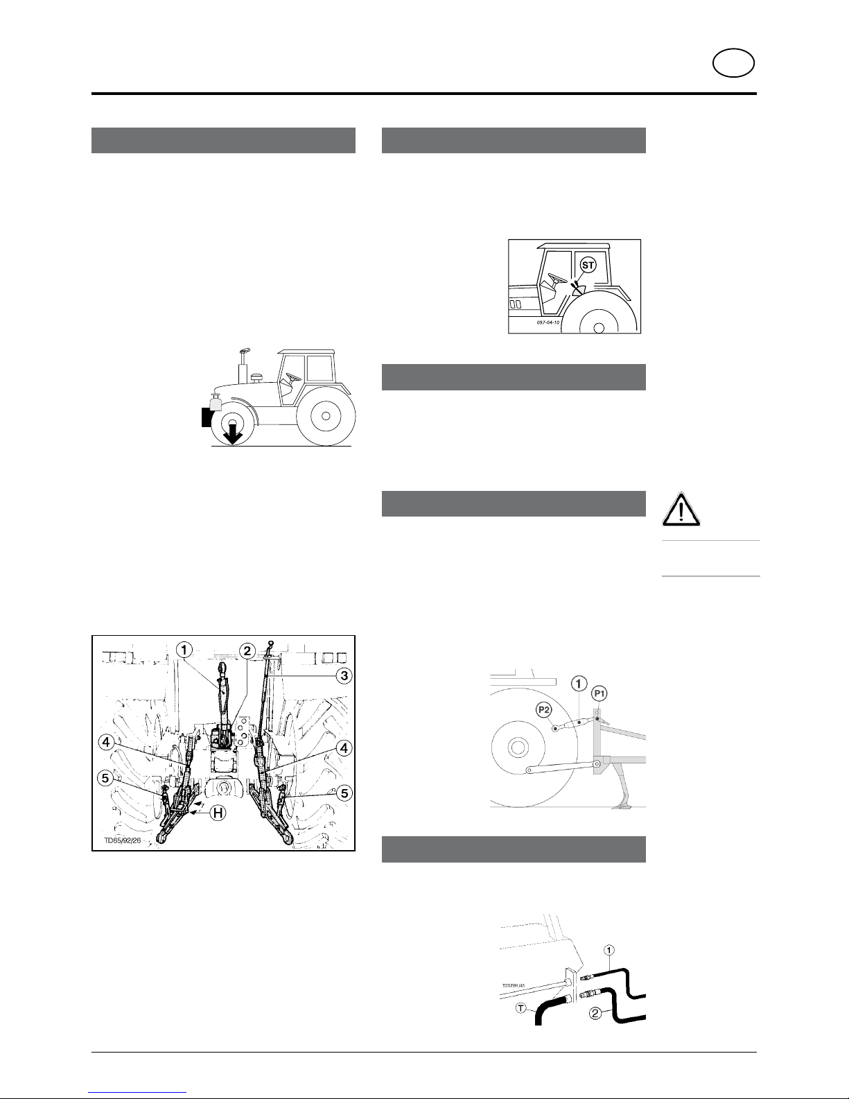
Lifting gear
- The left and right lifting struts (4) must be the same
length.
Adjust using adjuster (3).
-
If lifting struts (4) can be pinned at various positions
on the lower links, then select the back position (H). In
doing this, the tractor’s hydraulics will not be so greatly
overloaded.
-
Pin (2) upper link (1) in accordance with the manufacturer’s
specifications.
Setting-up for transportation
- Secure lower links with struts (5) so that attached
implement cannot swing out during transportation.
- The operating lever for the hydraulics must be secured
against lowering.
20%
Kg
Hydraulic control on the lifting gear
Control position:
For mounting and dismounting the implement and for
transportation.
The control position is the normal setting for the lifting
gear hydraulics.
T
h e m o u n t e d
implement remains at
the height (= position)
set by the servo-valve
(ST).
Preparing the cultivator
Mounting axle
Install correct mounting bar on tractor’s lifting gear
which corresponds to the connecting size (Category
II or III). See Spare Parts List also.
Connecting to tractor
- Switch tractor’s hydraulics to control position.
- Attach implement to lower link and secure with linch
pin.
Position upper link (1)
- Position upper link (1) so that the attachment point
(P1) on the implement is somewhat higher than the
attachment point (P2) on the tractor even during
operation.
C
onnecting hydraulic hoses
Double action control unit
- Connect pressure line (1) and oil-return pipe (2)
Safety
points:
see supplement-A1
Pkt. 8a. - 8h.)

GB
connecting to tractor
- 6 -
0700_GB-ANBAU_9765
- Make sure that swivel area is free and that nobody is
standing in the danger area.
- Move servo-valve (ST) to „rais“ position
The sideparts of the machine are swivelled into position
"Transport position".
-
Close hydraulic stop valve (A)
Conversion from transport to working position
- Open hydraulic stop valve (A)
- Make sure that swivel area is free and that nobody is
standing in the danger area.
-
Move servo-valve (ST) to „lower“ position
The sideparts of the machine are swivelled into position
"Working position".
Transport position SYNKRO
Safety Precaution!
Changing from
working to
transport position
is only to be
carried out on
even, firm ground.
Conversion from working to transport position
Working position SYNKRO
(A)
X = 4 m (Synkro 4003 K)
X = 5 m (Synkro 5003 K)
X = 6 m (Synkro 6003 K)

GB
connecting to tractor
- 7 -
0700_GB-ANBAU_9765
Driving on public roads
• Observe the official regulations of your country.
• Parts and attachment
- see spare parts list
• Travelling on open roads may only be carried out as
described in chapter "Transport position".
Total width of implement in the work position:
- more than 3m
Total width of implement in the transport
position:
see Technical Data
Parking, cleaning and winter storage of the
implement
• Observe the points in the chapter „Maintenance“!
Using additional implements.
Mount additional implements to the cultivator, such
as the drillbox (DB), according to the manufacturer’s
instructions.
• Do not overload the cultivator. If in doubt contact our
customer service office.
•
In addition, observe the power range limits of the tractor
in use.
- 8 -
0700_GB-EINsTELLUNGEN_9762
adjustments
DK
Setting for operation
1. The implement must be attached to the tractor in a horizontal
position, it should not hang to one side.
2. The front and rear tine rows must penetrate the ground at the
same depth (working depth).
The
frame should sit parallel to the ground surface as seen
longitudinally.
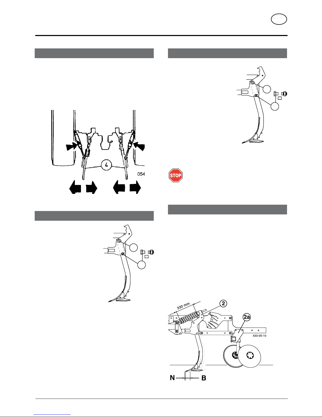
3.
Fix the lower link (4) in such a way that the machine cannot swing
out sideways.
Equipment variants and wearing parts
Rigid tines (basic equipment)
Spring-mounted tines (optional extra)
• Can be backfitted on all types
Backfitting kit (2 & 2a)
(see spare parts list)
-
Basic setting = 330 mm
Wearing parts
- are screwed to the tines and can therefore be replaced at little
cost.
Overloading
Shearing screws
Tines are secured with shearing
screws.
The shearing screw (pos. 7) breaks
when overloaded and the tine
swings upward.
-
Remove the shearing screw
remains.
-
Loosen hexagonal screw (6).
- Swing tine back to working
position.
-
Insert new shearing screw and
tighten both screws.
I
mportant!
Only use genuine shearing screws (see spare parts
list) of appropriate dimension and quality. Under no
circumstances use screws with a greater or lesser
strength.
344-05-14
7
6
Hollow discs
- serve to level out the ground surface evenly.
Setting the hollow discs
• This setting should suit the relevant operating conditions (type
of ground, speed and straw layer on the ground).
• The hollow discs are always set at the required working
depth.
Only fine adjustment is necessary
344-05-14
7
6
adjustments
- 9 -
0700_GB-EINsTELLUNGEN_9762
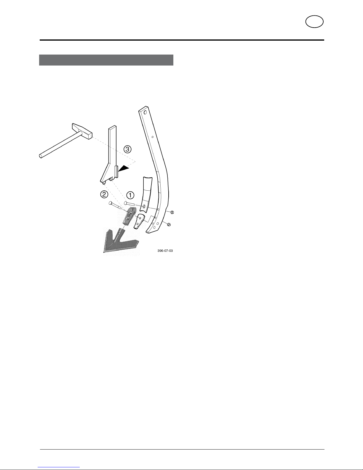
Share quick-change
1. Use change key
2. Press down on lock button
3. Release share with a hammer blow
DK

- 10 -
0700_GB-EINsATz_9762
use
GB
1. Check for proper attachment.
Before initial operation check all screws for tightness and retighten
if necessary.
2. Set required working depth.
Position both the support arms with pins (6) accordingly.
3. Swing hollow discs (left and right) into working position
(A)
Make sure pins (7) are inserted accordingly
4. Lower implement to the ground using tractor’s lifting
gear.
Drive a few metres into the working area then check the working
depth and the closing of the tine furrows.
5. If necessary, adapt tine angle to the operating conditions
(SK, EX).
Pos. B: Swivel the tines back (pos. B) if the required working
depth is not being obtained, e.g. with very heavy
ground.
Pos. N: Normal tine position.
SK
B
N
344-05-11
TD 34/95/20
5
2/3
1/3
Starting work
Basic setting for hollow discs: 1/3 of the total working depth.
O: Upper pins
To secure the trailer
U: Lower pins
For setting the working depth
Working depth difference from hole to hole of approx. 1.5 cm
Always change both pins!

- 11 -
GB
0400_GB-BA-Allg. Wartung
Parking in the ope
When parking in the open for
long periods of time, clean
piston rods and then coat
with grease.
FETT
Safety
points!
• Turn engine off
when adjustment,
service and repair
work is to be
done.
•
Do not work under the machine
without safe
support.
•
Retighten all
screws after the
first hours of
operation..
General maintenance hints
In order to keep the implement in
good condition after long periods
of operation, please observe the
following points:
-
Tighten all screws after the first
hours of operation.
In particular check:
- blade screws on the mowers
- tine screws on the swather and tedder.
Spare part
a. The original components and accessories have
been designed especially for these machines and
appliances.
b. We want to make it quite clear that components and
accesories that have not been supplied by us have
not been tested by us.
c.
The installation and/or use of such products can,
therefore, negatively change or influence the
construction characteristics of the appliance. We are
not liable for damages caused by the use of components
and accessories that have not been supplied by us.
d. Alterations and the use of auxiliary parts that are
not
permitted by the manufacturer render all liability
invalid.
Cleaning of machine parts
Attention! Do not use high-pressure washers for the
cleaning of bearing- and hydraulic parts.
- Danger of rust!
- After cleaning, grease the machine according to the
lubrication chart and carry out a short test run.
-
Cleaning with too high pressure may do damage to
varnish.
Safety point
• Turn engine off when adjustment, service and repair
work is to be done.
Hydraulic unit
Caution! Danger of injury or infection!
Under high pressure, escaping fluids can penetrate
the skin. Therefore seek immediate medical help!
After the first 10 operating hours and then every
consecutive 50 operating hours
- Check the hydraulic unit and lines for tightness and
retighten screw connections if necessary.
Before operation
- Check hydraulic hoses for wear.
Replace worn or damaged hydraulic hoses immediately.
The replacement hoses must meet the manufacturer’s
technical requirements.
Hose
lines are subject to natural ageing. The period of
use should not exceed 5 – 6 years.
Winter storage
- Thoroughly clean machine before storage.
- Put up protection against weather.
- Change or replenish gear oil.
- Protect exposed parts from rust.
- Lubricate all greasing points according to lubrication
chart.
Drive shafts
- see notes in the supplement
For maintenance please note!
The instructions in this operating manual are always
valid.
In case there are no special instructions available, then
the notes in the accompanying drive shaft manufacturer´
instructions are valid.
Repair Instructions
Please refer to
repair instructions
in supplement (if
available)
maintenance

0500-GB WArTUNG_965.p65
MAINTENANCE
GB
- 12 -
Advice for general maintence
In order to keep the machine in good condition even after
a longer period of operation, please observe the following
notes.
Safety points
• Turn engine off when adjustment, service and repair work
is to be done.
•
Do not work under the machine without safe support.
- Afterthersthoursofoperation,tightenallscrews.
Spare parts
a. The original components and accessories have been
designed especially for these machines and appliances.
b. We want to make it quite clear that components and
accesories that have not
been supplied by us have
not been tested by us.
c.
The i n s t allation a n d/
or us e o f s uch prod
uct s ca n , th e refore ,
neg ativel y ch ange or
inuencetheconstruction
characteristics of the appliance. We are not liable for damages caused by the use of
components and accessories that have not been supplied
by us.
d. Alterations and the use of auxiliary parts that are not permitted
by the
manufacturer render all liability invalid.
Hydraulic unit
Caution! Danger of injury or infection!
Under high pressure, escaping fluids
can penetrate the skin. Therefore seek
immediate medical help!
After the first 10 operating hours and
then every consecutive 50 operating
hours
- Check the hydraulic unit and lines for tightness and retighten
screw connections if necessary.
Before operation
- Check hydraulic hoses for wear.
Replace worn or damaged hydraulic hoses immediately. The
replacement hoses must meet the manufacturer’s technical
requirements.
Cleaning of machine parts
Attention!
Do n ot u se h igh -pre ssur e
washers for the cleaning of
bearing- and hydraulic parts.
- Danger of rust!
- After cleaning, grease the
machine according to the
lubrication chart and carry out a short test run.
-
Cleaning with too high pressure may do damage to varnish.
Winter storage
- Thoroughly clean the implement
- After cleaning, grease all greasing points and evenly apply
grease to the bearings (e.g. carry out a short trial run).
-
Protect exposed parts against rusting with an environmentally
safe protective agent.
-
Garage the implement where it is weather protected.

0500-GB WArTUNG_965.p65
MAINTENANCE
GB
- 13 -
Greasing points
Bearing
• Hollow discs
• „Rotopack“ tine roller
• Cage drum roller
• Spring-mounted tines
100 ha20
h
8
h
495.777
Every 100 hectares
• Check bearing bushes wear.
- Replace worn bearing brushes!
Every 20 operating hrs.
• Grease bearings
Every 8 operating hrs.
• Retighten screws
Description of transfers
FETT

GB
- 14 -
0900_GB-SCHAR-VARi Anten_0965
SHARE VARIANTS
1. Pointed share with winged shares
(Standard)
• Working depth, ploughing depth: 5 – 15 cm
• Hoeing: very good
• Mixing: very good
• Levelling: very good
• Without winged shares: deeper cultivation
With winged shares: total area cultivation
Share variants
3. Double-diamond share with wings
(Optional extra)
• Working depth, ploughing depth: 5 - 15 cm
• Hoeing: very good
• Mixing: very good
• Levelling: very good
• Without winged shares: deeper cultivation
With winged shares: total area cultivation
• Double-diamond is rotatable, therefore usable twice
• No guiding plate
2. Solo pointed share
(Lower price)
• Working depth, ploughing depth: 10 - 30 cm
• Hoeing: very good
• Mixing: from 10 cm good mixing
• Levelling: very good
• Without winged shares: deeper cultivation

GB
SHARE VARIANTS
- 15 -
0900_GB-SCHAR-VARi Anten_0965
4. Solo double-diamond
(Optional extra)
• Working depth, ploughing depth: 10 - 30 cm
• Hoeing: very good
• Mixing: from 10 cm good mixing
• Levelling: very good
• Without winged shares: deeper cultivation
• Double-diamond is rotatable, therefore usable twice
• No guiding plate
6. Quick changer with narrow share
(Optional extra)
• Working depth, ploughing depth: 10 - 30 cm
• Hoeing: very good
• Mixing: from 10 cm good mixing
• Levelling: very good
• Without winged shares: deeper cultivation
5. Quick changer with flat share
(Optional extra)
• Working depth, ploughing depth: 5 - 10
• Hoeing: very good
• Mixing: from 10 cm good mixing
• Levelling: very good
• Winged shares: total area cultivation

GB
SHARE VARIANTS
- 16 -
0900_GB-SCHAR-VARi Anten_0965
Overview of share variants
1.
Poin t e d share
w i th w in ge d
shares
2.
So l o po i nte d
share
3.
Double-diamond
with wings
4.
So l o do u bl e-
diamond
5.
Quick ch anger
with flat share
6.
Quick ch anger
w i t h n a r r o w
share
Working
depth,
Ploughing depth
5 – 15 cm 10 – 30 cm 5 – 15 cm 10 – 30 cm 5 – 15 cm 10 – 30 cm
Hoeing Very
good Very good Very good Very good Very good Very good
Mixing Very
good
From 10 cm
good mixing
Very good
From 10 cm
good mixing
Very good
From 10 cm
good mixing
Levelling Very
good Very good Very good Very good Very good Very good
Difference:
Wit
h or without
winged share
Total area
cultivation
Deeper
cultivation
T
otal area
cultivation
Deeper
cultivation
Total area
cultivation
Deeper
cultivation

- 17 -
0800-GB TechDat _9765
GB
Position of Vehicle Identification Plate
The factory number (Masch.-Nr.) is imprinted on the accompanying Vehicle
Identification Plate (as shown) and on the frame. Guarantee issues and further
inquiries cannot be processed without the factory number being stated.
Please enter the number onto the front page of the operating manual immediately
after taking delivery of the vehicle/implement.
Technical data
All data subject to alteration.
Necessary connections
• 1 double-action hydraulic plug-in connection
Operating pressure min.: 150 bar
Operating pressure max.: 200 bar
TECHNICAL DATA
Description
SYNKRO 4003 K +T
Type 9763
SYNKRO 5003 K +T
Type 9764
SYNKRO 6003 T
Type 9765
Working width [m] 4 5 6
Transport width [m] 3 3 3
Working depth
No. of tools 14 14 22
Row gap
[mm] 750 750 750
Line gap
[mm] 280 280 270
Frame height
[mm] 800 800 800
Attachment
Cat II, Cat III Cat II, Cat III Cat II, Cat III
Power r
equirement from [kw/hp] 110/150 110/150 160/220
W
eight – basic implement [kg]
with spring elements [kg]
2000
2430
2000
2430
2730
3456
W
eight - Tubular cage drum roller Ø 540 [kg]
Double roller [kg]
Oscillating rotor pack [kg]
Cutting ring roller [kg]
Cutting packer roller [kg]
440
580
-740
820
1200
440
580
-740
820
1200
--
680
-1060
1100
1200
Noise pollution level <70 dB (A) <70 dB (A) <70 dB (A)

- 18 -
0800-GB TechDat _9765
TECHNICAL DATA
GB
Defined use of the cultivator according to the manufacturer’s instructions.
The „SYNKRO 4003 K+T, SYNKRO 5003 K+T, SYNKRO 6003 T“ cultivator is intended solely for normal use in agricultural work.
• To prepare the upper layer of arable land for sowing which is to follow.
Any other uses outside of this are regarded as not in accordance with the defined use.
The manufacturer will not be held liable for any damages resulting from misuse. The risk is carried by the user alone.
• The keeping of operating, servicing and maintenance requirements as specified by the manufacturer also come under the heading of „defined
use“.
Optional equipment
1 Edge disc - left
Edge disc - right
2 Automatic stump-jump device
Can be backfitted to all SYNKRO types
3 Lighting
Trailing implements
5 Tubular cage drum roller 540 mm
7 Double roller
8 Cutting ring roller
9 Cutting packer roller
433-05-13
2

- 19 -
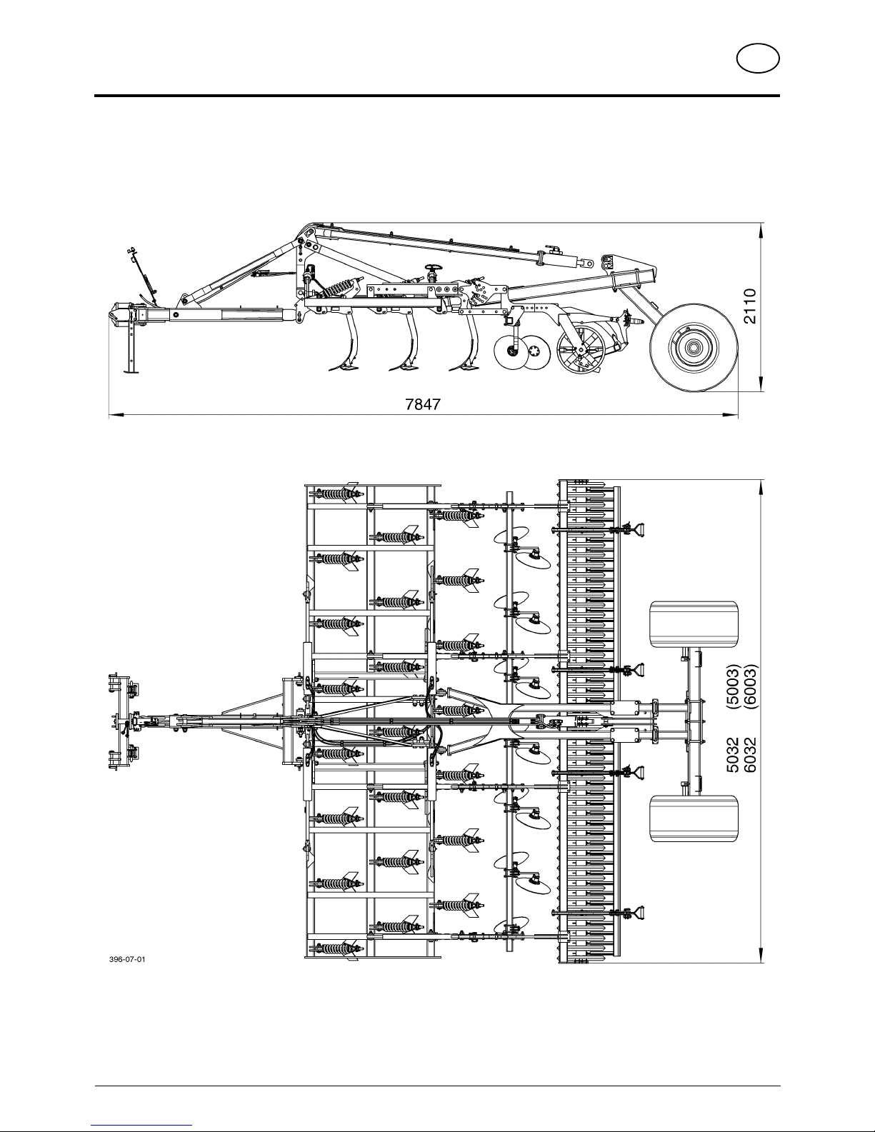
0700_GB-MassBlatt_9765
GB
All data subject to alteration without notice
dimensions
SYNKRO 4003 K
SYNKRO 5003 K
SYNKRO 6003 K
- 20 -
0700_GB-MassBlatt_9765
GB
dimensions
All data subject to alteration without notice
SYNKRO 5003 +T
SYNKRO 6003 +T

- 21 -
0700-GB CArGO_9765
GB
running gear
Running gear 1)
Safety advice:
See supplement A1
(Pt. 8a – h)
1) Optional extra
P
A = Working position
V = Pre-turning position
T = Transport position
Safety advice!
Changing from
working to
transport position
and vice-versa
is to be carried
out on even, firm
ground.
Ensure the swivel
range is free and
no-one is in the
danger area.
Attaching
- Set tractor lower link in centre
- Fix hydraulic lower link (U) so that device cannot swing
out sideways
-
against erratic, unstable machine trailing
- Couple pendulum axle (P) to lower link
- Properly secure the coupling bolts (1)
- Raise both parking supports (2) into the transport
position
-
Secure with linch pin (3)
Operation
The tractor hydraulic and lifting gear is relieved when
transporting through the running gear.
Working position (A)
• Lift the running gear with the hydraulic servo-valve
- the machine rests on the ground
Pre-turning position (V)
• Lower the running gear with the hydraulic servovalve
- the wheels run on the ground
Transport position (T)
• Fold the machine in the transport position
• Lower the running gear with the hydraulic servovalve
-
the wheels run on the ground

GB-Anhang Titelblatt _BA-Allgemein
GB
supplement

GB-Anhang Titelblatt _BA-Allgemein
GB
The decision must be made, ”original” or ”imitation”? The decision is often governed
by price and a ”cheap buy” can sometimes be very expensive.
Be sure you purchase the ”Original” with the cloverleaf symbol!
• Quality and precise fitting
- Operating safety.
• Reliable operation
• Longer lasting
- Economy
•
Guaranteed availability through your
Pöttinger Sales Service.
Things will run better with
genuine Pöttinger parts
The original cannot be copied ...

9400_GB-Anhang A_Sicherheit
supplement - a
Recommendations for work safety
- A 1 -
20%
Kg
Recommendations for work safety
All points refering to safety in this manual are indicated
by this sign.
1.) Defined use
a. See "Technical Data".
b. The keeping of operating, service and maintenance requirements
layed down by the manufacturer also come under the heading of
"defined use".
2.) Spare parts
a. The original components and accessories have been designed
especially for these machines and appliances.
b. We want to make it quite clear that components and accesories
that have not been supplied by us have not been tested by us.
c.
The installation and/or use of such products can, therefore,
negatively change or influence the construction characteristics
of the appliance. We are not liable for damages caused by the
use of components and accessories that have not been supplied
by us.
d. Alterations and the use of auxiliary parts that are not permitted
by the
manufacturer render all liability invalid.
3.) Protection devices
All protection devices must remain on the machine and be
maintained in proper condition. Punctual replacement of worn
and damaged covers is essential.
4.) Before starting work
a. Before commencing work, the operator must be aware of all
operating devices and functions. The learning of these is too late
after having already commenced operation!
b. The vehicle is to be tested for traffic and operating safety before
each operation.
5.) Asbestos
- Certain sub-supplied components of the
vehicle may contain asbestos due to technical
reasons. Observe the warning on spare
parts.
6.) Transport of persons prohibited
a. The transport of persons on the machine is not permitted.
b. The machine may only be driven on public roads when in the
position stipulated for road transport.
7.) Driving ability with auxiliary equipment
a. The towing vehicle is to be sufficiently equiped with weights at the
front or at the rear in order to guarantee the steering and braking
capacity (a minimum of 20% of the vehicle’s tare weight on the
front axle).
b
. The driving ability is
influenced by ground
conditions and by the
auxiliary
equipment. The
driving must be adapted
to the corresponding
t
errain a nd ground
conditions.
c. When driving through
curves with a connected
a
ppliance, observe the
ra dius and swi ngin g
mass of the appliance.
d. When travelling in a curve with attached or semimounted
implements, take into account the working range and swing mass
of the implement!
8.) General
a. Before attaching implement to three-point linkage, move system
lever into a position whereby unintentional raising or lowering is
ruled out!
b. Danger of injury exists when coupling implement to tractor!
c. Danger of injury through crushing and cutting exists in the three-
point linkage area!
d.
Do not stand between tractor and implement when using three-
point linkage external operation!
e.
Attach and detach drive shaft only when motor has stopped.
f. When transporting with raised implement, secure operating lever
against lowering!
g.
Before leaving tractor, lower attached implement to the ground
and remove ignition key!
h.
Nobody is to stand between tractor and implement without tractor
being secured against rolling using parking brake and/or wheel
chocks!
i.
For all maintenance, service and modification work, turn driving
motor off and remove universal drive.
9.) Cleaning the machine
Do not use high-pressure washers for the cleaning of bearing- and
hydraulic parts.

Leistung und Lebensdauer der Maschine sind
von sorgfältiger Wartung und der Verwendung
gu t e r B e t ri e bs s t of f e a b h än g i g. Un s e r e
Betriebsstoffauflistung erleichtert die richtige Auswahl
geeigneter Betriebsstoffe.
Im Schmierplan ist der jeweils einzusetzende
Betriebsstoff durch die Betriebsstoffkennzahl (z.B.
“III”) symbolisiert. Anhand von “Betriebsstoffkennzahl”
kann das geforderte Qualitätsmerkmal und das
en tspre che nde Produkt der Mi ner alö lfi rmen
festgestellt werden. Die Liste der Mineralölfirmen
erhebt keinen Anspruch auf Vollständigkeit.
Getriebeöl gemäß Betriebsanleitung - jedoch
mindestens 1 x jährlich wechseln.
- Ölablaßschraube herausnehmen, das Altöl
ausl a u f e n lasse n u n d ord n u n g sgemäß
entsorgen.
Vor Stillegung (Winterperiode) Ölwechsel durchführen
und alle Fettschmierstellen abschmieren. Blanke
Metallteile außen (Gelenke, usw.) mit einem Produkt
gemäß “IV” in der umseitigen Tabelle vor Rost
schützen.
I II III IV V VI VII
(II)
Ö
L
(IV)
FE T T
- D 1 -
Betriebsstoff-Kennzahl
Lubricant indicator
Code du lubriant
Numero caratteristico del
lubricante
Smeermiddelen code
gefordertes Qualitätsmerkmal
required quality level niveau
de performance demandé
caratteristica richiesta di
qualità
verlangte kwaliteitskenmerken
Getriebeöl SAE 90 bzw. 85
W-140 gemäß API-GL 5
gear oil SAE 90 resp. SAE 85
W-140 according to API-GL 5
huile transmission SA 90 ou
SAE 85 W-140, niveau API
GL 5
oilio per cambi e differenziali
SAE 90 o SAE 85 W-140 se-
condo
specicheAPI-GL5
Komplexfett (DIN 51 502: KP 1R)
complex grease
graisse complexe
grasso a base di saponi comp-
lessi
Getriebeießfett
(DIN 51 502:GOH
transmission grease
graisse transmission
grasso
uidoperriduttorie
motoroduttori
Li-Fett (DIN 51 502, KP 2K)
lithium grease
graisse au lithium
grasso al litio
Getriebeöl SAE 90 bzw. SAE 85 W-140
gemäß API-GL 4 oder API-GL 5
gear oil, SAE 90 resp. SAE 85 W-140
according to API-GL 4 or API-GL 5
huile transmission SAE 90 ou
SAE 85 W-140, niveau API-GL 4 ou
API-GL 5
olio per cambi e differenziali SAE 90
o
SAE85W-140secondospeciche
API-GL 4 o API-GL 5
Motorenöl SAE 30 gemäß
API CD/SF
motor oil SAE 30
according to API CD/SF
huile moteur SAE 30 niveau
API CD/SF
oilo motore SAE 30 secondo
speciche
APICD/SF
HYDRAULIKöL HLP
DIN 51524 Teil 2
Siehe Anmerkungen
*
**
***
The performance and the lifetime of the farm
machines are highly depending on a careful
main tenance and appl icati on of cor re ct
lubricants. our schedule enables an easy
selection of selected products.
The applicable lubricants are symbolized (eg.
“III”). According to this lubricant product code
number the specification, quality and brandname
of oil companies may easily be determined.
The listing of the oil companies is not said to
be complete.
Gear oils according to operating instructions
- however at least once a year.
-
Take out oil drain plug, let run out and duly
dispose waste oil.
Before garaging (winter season) an oil change and
greasing of all lubricating points has to be done.
Unprotected, blanc metal parts outside (joints,
etc.) have to be protected against corrosion with
a group "Iv" product as indicated on the reverse
of this page.
Le bon fonctionnement et la longévité
des machines dépendent d’un entre-tien
soigneux et de l’utilisation de bons lubrifiants.
Notre liste facilite le choix correct des
lubrifiants.
Sur le tableau de graissage, on trouve un code
(p.ex."III") se référant à un lubrifiant donné.
En consultant ce code on peut facilement
déterminer la spécification demandée du
lubrifiant. La liste des sociétés pétrolières
ne prétend pas d’être complète.
Pour l’huile transmission consulter le cahier
d’entretien - au moins une fois par an.
- retirer le bouchon de vidange, laisser
l'huile s'écouler et l'éliminer correcte-
ment.
Avant l’arrêt et hiver: vidanger et grais-ser.
métaux nus à l' extérieur protéger avec un
produit type “Iv” contre la rouille (consulter
tableau au verso).
L'efficienza e la durata della macchina dipendono
dall'accuratezza della sua manutenzione e dall'impiego
dei lubrificanti adatti. Il nostro elenco dei lubrificanti Vi
agevola nella scelta del lubrificante giusto.Il lubrificante
da utilizzarsi di volta in volta è simbolizzato nello schema
di lubrificazione da un numero caratter-istico (per es.
"III"). In base al "numero caratteristico del lubrificante"
si possono stabilire sia la caratteristica di qualità che il
progetto corrispondente delle compagnie petrolifere.
L'elenco delle compagnie petrolifere non ha pretese di
completezza.
Motori a quattro tempi: bisogna effettuare il cambio
dell'olio ogni 100 ore di funzionamento e quello dell'olio
per cambi come stabilito nel manuale delle istruzioni per
l'uso (tuttavia, almeno 1 volta all'anno).
-
Togliere il tappo di scarico a vite dell’olio; far scolare
l’olio e eliminare l’olio come previsto dalla legge anti-
inquinamento ambientale.
Effettuare il cambio dell'olio ed ingrassare tutte le parti
che richiedono una lubrificazione a grasso prima del fermo
invernale della macchina. proteggere dalla ruggine tutte le
parti metalliche esterne scoperte con un prodotto a norma
di "Iv" della tabella riportata sul retro della pagina.
prestaties en levensduur van de
ma chi nes zijn a fhankel ijk va n
een zorgvuldig onderhoud en het
gebruik van goede smeermiddelen.
Dit schema vergemakkeli jkt de
goede keuze van de juiste smeer-
middelen.
Olie in aandrijvingen volgens de ge-
bruiksaanwijzing verwisselen - echter
tenminste 1 x jaarlijks.
- Aftapplug er uit nemen, de olie
aftappen en milieuvriendelijk
verwerken.
Voor het buiten gebruik stellen (win-
terperiode) de olie-wissel uitvoeren
en all e vetnipp el smeerpunte n
doorsmeren. Blanke metaaldelen
(koppelingen enz.) met een product
uit groep "Iv" van de navolgende tabel
tegen corrosie beschermen.
D
Betriebsstoffe
Ausgabe 1997
GB
Lubricants
Edition 1997
F
Lubrifiants
Édition 1997
I
Lubrificanti
Edizione 1997
NL
Smeermiddelen
Uitgave 1997

-
OSO 32/46/68
ARNICA 22/46
MOTOROIL HD 30
SIGMA MULTI 15W-40
SUPER TRACTOROIL UNIVERS.
15W-30
ROTRA HY 80W-90/85W-140
ROTRA MP 80W-90/85W-140
GR MU 2 GR SLL
GR LFO
ROTRA MP 80W-90
ROTRA MP 85W-140
VITAM GF 32/46/68
VITAM HF 32/46
SUPER KOWAL 30 MULTI TURBO-
RAL SUPER TRAKTORAL 15W-30
GETRIEBEÖL EP 90 GETRIEBEÖL
HYP 85W-90
ARALUB HL 2 ARALUB FDP 00
ARALUB FK 2
GETRIEBEÖL HYP 90
AGIP
ARAL
IV
ANMERKUNGEN
III VIV VIIII I
Firma
(IV)
FE TT
(II)
ÖL
HYDRAULIKÖL HLP 32/46/68
SUPER 2000 CD-MC *
HYDRA HYDR. FLUID * HYDRAU-
LIKÖL MC 530 ** PLANTOHYD
40N ***
SUPER 2000 CD-MC
SUPER 2000 CD
HD SUPERIOR 20 W-30
HD SUPERIOR SAE 30
SUPER 8090 MC
HYPOID 80W-90
HYPOID 85W-140
MULTI FETT 2
SPEZIALFETT FLM
PLANTOGEL 2 N
GETRIEBEFLIESSFETT NLGI 0
RENOLIT DURAPLEX EP 00
PLANTOGEL 00N
RENOPLEX EP 1 HYPOID 85W-140
BAYWA
AVILUB RL 32/46
AVILUB VG 32/46
MOTOROIL HD 30
MULTIGRADE HDC 15W-40 TRAC-
TAVIA HF SUPER 10 W-30
GETRIEBEÖL MZ 90 M MULTIHYP
85W-140
AVIA MEHRZWECKFETT
AVIA ABSCHMIERFETT
AVIA GETRIEBEFLIESSFETT
AVIALUB SPEZIALFETT LD GETRIEBEÖL HYP 90 EP MULTIHYP
85W-140 EP
AVIA
ENERGOL SHF 32/46/68 VISCO 2000
ENERGOL HD 30
VANELLUS M 30
GEAR OIL 90 EP
HYPOGEAR 90 EP
ENERGREASE LS-EP 2 FLIESSFETT NO
ENERGREASE HTO
OLEX PR 9142 HYPOGEAR 90 EP
HYPOGEAR 85W-140 EP
BP
HYSPIN AWS 32/46/68 HYSPIN
AWH 32/46
RX SUPER DIESEL 15W-40
POWERTRANS
EPX 80W-90
HYPOY C 80W-140
IMPERVIA MMO CASTROLGREASE LMX EPX 80W-90
HYPOY C 80W-140
CASTROL
WIOLAN HS (HG) 32/46/68
WIOLAN HVG 46 **
WIOLAN HR 32/46 ***
HYDROLFLUID *
MULTI-REKORD 15W-40
PRIMANOL
REKORD 30
HYPOID-GETRIEBEÖL
80W-90, 85W-140
MEHRZWECKGETRIEBEÖL
80W-90
WIOLUB LFP 2 WIOLUB GFW
WIOLUB AFK 2 HYPOID-GETRIEBEÖL
80W-90, 85W-140
ENAK HLP 32/46/68
ENAK MULTI 46/68
SUPER EVVAROL HD/B SAE 30
UNIVERSAL TRACTOROIL SUPER
HYPOID GA 90
HYPOID GB 90
HOCHDRUCKFETT LT/SC 280 GETRIEBEFETT MO 370
EVVA CA 300 HYPOID GB 90
HLP 32/46/68
HLP-M M32/M46
MOTORÖL 100 MS SAE 30
MOTORÖL 104 CM 15W-40 AUS-
TROTRAC 15W-30
GETRIEBEÖL MP 85W-90 GETRIE-
BEÖL B 85W-90 GETRIEBEÖL C
85W-90
LORENA 46
LITORA 27
RHENOX 34
-
GETRIEBEÖL B 85W-90 GETRIEBE-
ÖL C 85W-140
OLNA 32/46/68
HYDRELF 46/68
PERFORMANCE 2 B SAE 30 8000
TOURS 20W-30 TRACTORELF ST
15W-30
TRANSELF TYP B 90 85W-140
TRANSELF EP 90 85W-140
EPEXA 2
ROLEXA 2
MULTI 2
GA O EP
POLY G O
MULTIMOTIVE 1 TRANSELF TYP B 90 85W-140
TRANSELF TYP BLS 80 W-90
NUTO H 32/46/68
NUTO HP 32/46/68
PLUS MOTORÖL 20W-30 UNIFARM
15W-30
GEAROIL GP 80W-90 GEAROIL
GP 85W-140
MULTI PURPOSE GREASE H FIBRAX EP 370
NEBULA EP 1
GP GREASE
GEAR OIL GX 80W-90
GEAR OIL GX 85W-140
ULTRAMAX HLP 32/46/68 SUPER
TRAC FE 10W-30* ULTRAMAX
HVLP 32 **
ULTRAPLANT 40 ***
SUPER HPO 30
STOU 15W-30
SUPER TRAC FE 10W-30
ALL FLEET PLUS 15W-40
HP GEAR OIL 90
oder 85W-140
TRANS GEAR OIL 80W-90
MULTILUBE EP 2
VAL-PLEX EP 2
PLANTOGEL 2 N
RENOLIT LZR 000
DEGRALUB ZSA 000
DURAPLEX EP 1
TELLUS S32/S 46/S68 TELLUS
T 32/T46
AGROMA 15W-30
ROTELLA X 30
RIMULA X 15W-40
SPIRAX 90 EP
SPIRAX HD 90
SPIRAX HD 85/140
RETINAX A
ALVANIA EP 2
SPEZ. GETRIEBEFETT H SIMMNIA
GREASE O
AEROSHELL GREASE 22 DOLIUM
GREASE R
SPIRAX HD 90
SPIRAX HD 85W-140
AZOLLA ZS 32, 46, 68 EQUIVIS ZS
32, 46, 68
RUBIA H 30
MULTAGRI TM 15W-20
TOTAL EP 85W-90
TOTAL EP B 85W-90
MULTIS EP 2 MULTIS EP 200
MULTIS HT 1
TOTAL EP B 85W-90
DTE 22/24/25
DTE 13/15
HD 20W-20
DELVAC 1230
SUPER UNIVERSAL 15W-30
MOBILUBE GX 90
MOBILUBE HD 90
MOBILUBE HD 85W-140
MOBILGREASE MP
MOBILUX EP 004 MOBILPLEX 47
MOBILUBE HD 90
MOBILUBE HD 85W-140
RENOPLEX EP 1
HYPOID EW 90
HYPOID 85W-140
HYDRAULIKÖL HLP/32/46/68
HYDRAMOT 1030 MC * HYDRAU-
LIKÖL 520 **
PLANTOHYD 40N ***
MULTI 2030
2000 TC
HYDRAMOT 15W-30 HYDRAMOT
1030 MC
GETRIEBEÖL MP 90
HYPOID EW 90
HYPOID 85W-140
MEHRZWECKFETT
SPEZIALFETT GLM
PLANTOGEL 2 N
GETRIEBEFLIESSFETT
PLANTOGEL 00N
HYDRAN 32/46/68 DELTA PLUS SAE 30
SUPER UNIVERSAL OIL
PONTONIC N 85W-90 PONTONIC
MP 85W-90 85W-140
SUPER UNIVERSAL OIL
MARSON EP L 2
NATRAN 00
MARSON AX 2 PONTONIC MP 85W-140
RENOPLEX EP 1 RENOGEAR SUPER 8090 MC
RENOGEAR HYPOID 85W-140
RENOGEAR HYPOID 90
TITAN HYDRAMOT 1O3O MC
TITAN UNIVERSAL HD
RENOGEAR SUPER 8090 MC
RENOGEAR HYPOID 85 W-140
RENOGEAR HYPOID 90
RENOSOD GFO 35
DURAPLEX EP 00
PLANTOGEL 00N
ELAN
FUCHS
GENOL
MOBIL
RHG
SHELL
TOTAL
ELF
ESSO
EVVA
FINA
VALVOLINE
VEEDOL
RENOLIN B 10/15/20 RENOLIN B
32 HVI/46HVI
EXTRA HD 30
SUPER HD 20 W-30
MEHRZWECKGETRIEBEÖlSAE90
HYPOID EW 90
MEHRZWECKFETT
RENOLIT MP
DURAPLEX EP
RENOSOD GFO 35
RENOPLEX EP 1 HYPOID EW 90
-
-
ANDARIN 32/46/68 HD PLUS SAE 30
MULTIGRADE SAE 80/90 MULTI-
GEAR B 90
MULTIGEAR C SAE 85W-140
MULTIPURPOSE
MULTIGEAR B 90
MULTI C SAE 85W-140
WINTERSHALL
HP GEAR OIL 90
oder 85W-140
RENOLIN 1025 MC ***
TITAN HYDRAMOT 1030 MC **
RENOGEAR HYDRA *
PLANTOHYD 40N ***
RENOLIT MP
RENOLIT FLM 2
RENOLIT ADHESIV 2
PLANTOGEL 2 N
CASTROLGREASE LM
- D 2 -
* Bei Verbundarbeit mit
Naßbremsen-schlep-
pern ist die internatio-
naleSpezikationJ20
A erforderlich
** Hydrauliköle
HLP-(D) + HV
***HydrauliköleaufPan-
zenölbasis HLP + HV
Biologisch abbaubar,
deshalb besonders
umweltfreundlich

0000-GB ZUSINFO / BA-EL ALLG.
GB
- Z.27 -
important! additional information
see instruction handbook of the tractor
see price list and/or instruction handbook of the implement
to be measured
Consideration of rear mounted implement and front/rear combinations
1. CALCULATION OF MINIMUM BALLASTING AT THE FRONT G
V min
Record the calculated minimum ballasting which is needed at the front of the tractor into the table.
Front mounted implement
2. CALCULATION OF THE MINIMUM G
H min
Record the calculated minimum ballasting which is needed at the rear of the tractor into the table.
For the calculation you need the following data:
TL [kg]
T
V
[kg]
T
H
[kg]
G
H
[kg]
G
V
[kg]
unladen weight of tractor
front axle load of unladen tractor
rear axle load of unladen tractor
combined weight of rear mounted implement/rear
ballast
combined weight of front mounted implement/front
ballast
distance from centre of gravity for
combined front mounted implement/front
ballast to front axle centre
Tractor wheelbase
distance from rear axle centre to centre
of lower link balls
distance from centre of lower link balls
to centre of gravity for combined rear
mounted implement/rear ballast
a [m]
b [m]
c [m]
d [m]
2
3
1
1
1
1
1
2
2
2
3
3
1
3
2
Combination of tractor and mounted implement
The mounting of implements on the front or rear three point linkage shall not result in exceeding the maximum permissible weight,
the permissible axle loads and the tyre load carrying capacities ot the tractor. The front axle of the tractor must always to be loaded
with at least 20 % of the unladen weight of the tractor.
Make sure before buying an implement that these conditions are fulfilled by carrying out the following calculations or by weighing the
tractor/implement combination.
Determination of the total weight, the axle loads, the tyre load carrying capacity and the necessary
minimum ballasting

0000-GB ZUSINFO / BA-EL ALLG.
GB
- Z.28 -
important! additional information
3. CALCULATION OF THE REAL FRONT AXLE LOAD T
V tat
(If with the front mounted implement (GV) the required minimum front ballasting (G
V min
) cannot be reached, the weight of the front mounted
implement has to be increased to the weight of the minimum ballasting at the front!)
Record the calculated real front axle load and the permissible front axle load of the tractor into the table.
4. CALCULATION OF THE REAL TOTAL WEIGHT G
tat
(If with the rear mounted implement (GH) the required minimum rear ballasting (G
H min
) cannot be reached, the weight of the rear mounted
implements has to be increased to at least the weight of the minimum ballasting at the rear!)
Record the calculated real and the permissible total weight given in the instruction handbook for the tractor into the table.
5. CALCULATION OF THE REAL REAR AXLE LOAD T
H tat
Record the calculated real and the permissible rear axle load given in the instruction handbook for the tractor into the table.
6. TYRE LOAD CARRYING CAPACITY
Record double the value (two tyres) of the permissible load carrying capacity into the table (see for instance documentation provided by the
tyre manufacturer).
Minimum ballasting
front/rear
Total weight
Front axle load
Rear axle load
Real value according to
calculation
Permissible value
according to
instruction handbook
D
ouble permissible tyre
load carrying capacity (two
tyres)
The minimum ballasting has to be attached to the tractor either in form of a mounted implement or
ballasting weight!
T
he calculated values must be less or equal (<) the permissible values!
Table

ALOIS PÖTTINGER Maschinenfabrik Gesellschaft m.b.H.
A-4710 Grieskirchen; Industriegelände 1
0600 GB-EG Konformitätserklärung
EC Certicate of Conformity
conforming to EEC Directions 98/37/EG
We ______________________________________________________________________
(name of supplier)
__________________________________________________________________________________
(full address of company - where this concerns authorized agents within the Common Market, also state the company
name and manufacturer)
declare in sole responsibility, that the product
__________________________________________________________________________
(make, model)
to which this certicate applies, conforms to the basic safety and health requirements of
EEC Directions 98/37,
(if applicable)
and to the other relevant EEC Directions.
__________________________________________________________________________
(title and/or number and date of issue of the other EEC Directions)
(if applicable)
To effect correct application of the safety and health requirements stated in the EEC Directions,
the following standards and/or technical specications were consulted:
__________________________________________________________________________
(title and/or number and date of issue of standards and/or specifications)
Appendix 1
____________________________ ____________________________________
(Place and date of issue) (Name and job function of authorized person)
GB
Cultivator
SYNKRO 4003 K +T, Type 9763
SYNKRO 5003 K +T, Type 9764
SYNKRO 6003 T, Type 9765
Grieskirchen, 07.11.2007
pa. Ing. W. Schremmer
Entwicklungsleitung

A emp re sa PÖT TIN GER Ge s.m .b. H
esforçase continuamente por melhorar os
seus produtos, adaptando-os à evolução
técnica.
Por este motivo, reservamonos o direito de modificar
as figuras e as descrições constantes no presente
manual, sem incorrer na obrigação de modificar
máquinas já fornecidas.
As características técnicas, as dimensões e os pesos
não são vinculativos.
A reprodução ou a tradução do presente manual de
instruções, seja ela total ou parcial, requer a autorização
por escrito da
ALoIS PÖTTINGER
Maschinenfabrik Gesellschaft m.b.H.
A-4710 Grieskirchen
Todos os direitos estão protegidos pela lei da prop-
riedade intelectual.
Im Zuge der technischen Weiterentwicklung
arbeitet die PÖTTINGER Ges.m.b.H ständig
an der Verbesserung ihrer Produkte.
Änderungen gegenüber den Abbildungen und
Beschreibungen dieser Betriebsanleitung müssen wir
uns darum vorbehalten, ein Anspruch auf Änderungen
an bereits ausgelieferten Maschinen kann daraus nicht
abgeleitet werden.
Technische Angaben, Maße und Gewichte sind
unverbindlich. Irrtümer vorbehalten.
Nachdruck oder Übersetzung, auch auszugsweise,
nur mit schriftlicher Genehmigung der
ALOIS PÖTTINGER
Maschinenfabrik Gesellschaft m.b.H.
A-4710 Grieskirchen.
Alle Rechte nach dem Gesetz des Urheberrecht
vorbehalten.
D
Beroende på den tekniska utvecklingen
arbe-tar PÖTTINGER Ges.m.b.H. på att
förbättra sina produkter.Vi måste därför
förbehålla oss förändringar gentemot avbildningarna
och beskrivningarna i denna bruksanvis-ning. Däremot
består det inget anspråk på förändringar av produkter
beroende av denna bruksanvisning.
Tekniska uppgifter, mått och vikter är oförbindliga.
Fel förbehållna.
Ett eftertryck och översättningar, även utdrag, får
endast genomföras med skriftlig tillåtelse av
ALoIS PÖTTINGER
Maschinenfabrik Gesellschaft m.b.H.
A – 4710 Grieskirchen
Alla rättigheter enligt lagen om upphovsmannarätten
förbehålls.
La société PÖTTINGER Ges.m.b.H améliore
constamment ses produits grâce au progrès
technique.
C'est pourquoi nous nous réser-vons le droit de
modifier descriptions et illustrations de cette notice
d'utilisation, sans qu'on en puisse faire découler un
droit à modifications sur des machines déjà livrées.
Caractéristiques techniques, dimensions et poids sont
sans engagement. Des erreurs sont possibles.
Copie ou traduction, même d'extraits, seulement avec
la permission écrite de
ALoIS PÖTTINGER
Maschinenfabrik Gesellschaft m.b.H.
A-4710 Grieskirchen.
Tous droits réservés selon la réglementation des
droits d'auteurs.
Following the policy of the PÖTTINGER Ges.
m.b.H to improve their products as technical
developments continue, PÖTTINGER
reserve the right to make alterations which must not
necessarily correspond to text and illustrations contained in this publication, and without incurring obligation
to alter any machines previously delivered.
Technical data, dimensions and weights are given as an
indication only. Responsibility for errors or omissions
not accepted.
Reproduction or translation of this publication, in
whole or part, is not permitted without the written
consent of the
ALoIS PÖTTINGER
Maschinenfabrik Gesellschaft m.b.H.
A-4710 Grieskirchen.
All rights under the provision of the copyright Act
are reserved.
PÖTTINGER Ges.m.b.H werkt permanent
aan de verbetering van hun producten
in he t k a der van hu n t e c hnis c he
ontwikkelingen. Daarom moeten wij ons veranderingen
van de afbeeldingen en beschrijvingen van deze
gebruiksaanwijzing voorbehouden, zonder dat daaruit
een aanspraak op veranderingen van reeds geieverde
machines kan worden afgeleid.
Technische gegevens, maten en gewichten zijn niet
bindend. Vergissingen voorbehouden.
Nadruk of vertaling, ook gedeeltelijk, slechts met
schriftelijke toestemming van
ALoIS PÖTTINGER
Maschinenfabrik Gesellschaft m.b.H.
A-4710 Grieskirchen.
Alle rechten naar de wet over het auteursrecht voor-
behouden.
La empresa PÖTTINGER Ges.m.b.H se
esfuerza contínuamente en la mejora
constante de sus productos, adaptándolos
a la evolución técnica. Por ello nos vemos obligados
a reservarnos todos los derechos de cualquier
modificación de los productos con relación a las
ilustraciones y a los textos del presente manual, sin
que por ello pueda ser deducido derecho alguno a la
modificación de máquinas ya suministradas.
Los datos técnicos, las medidas y los pesos se
entienden sin compromiso alguno.
La reproducción o la traducción del presente manual
de instrucciones, aunque sea tan solo parcial, requiere
de la autorización por escrito de
ALoIS PÖTTINGER
Maschinenfabrik Gesellschaft m.b.H.
A-4710 Grieskirchen.
Todos los derechos están protegidos por la ley de la
propiedad industrial.
La PÖTTINGER Ges.m.b.H è costantemente
al lavoro per migliorare i suoi prodotti
mantenendoli aggiornati rispetto allo
sviluppo della tecnica.
Per questo motivo siamo costretti a riservarci la facoltà
di apportare eventuali modifiche alle illustrazioni e alle
descrizioni di queste istruzioni per l’uso. Allo stesso
tempo ciò non comporta il diritto di fare apportare
modifiche a macchine già fornite.
I dati tecnici, le misure e i pesi non sono impegnativi.
Non rispondiamo di eventuali errori. Ristampa o
traduzione, anche solo parziale, solo dietro consenso
scritto della
ALoIS PÖTTINGER
Maschinenfabrik Gesellschaft m.b.H.
A-4710 Grieskirchen.
Ci riserviamo tutti i diritti previsti dalla legge sul diritto
d’autore.
Som led i den tekniske videreudvikling
arbejder PÖTTINGER Ges.m.b.H hele tiden
på at forbedre firmaets produkter.
Ret til ændringer i forhold til figurerne og beskrivelserne
i denne driftsvejledning forbeholdes, krav om
ændringer på allerede leverede maskinen kan ikke
udledes deraf.
Tekniske angivelser, mål og vægtangivelser er
uforpligtende.
Der tages forbehold for fejl.
Kopiering eller oversættelse, også delvis, kun med
skriftlig tilladelse fra
ALoIS PÖTTINGER
Maschinenfabrik Gesellschaft m.b.H.
A-4710 Grieskirchen.
Alle rettigheder forbeholdes iht. loven om ophavsret.
Som et ledd i den tekniske videreutviklingen
arbeider PÖTTINGER Ges.m.b.H. stadig
med forbedring av firmaets produkter.
Derfor tar vi forbehold om endringer i forhold til bildene
og beskrivelsene i denne bruksanvisningen, krav
om endringer på allerede leverte maskiner kan ikke
utledes fra dette.
Tekniske angivelser, mål og vekt er veiledende. Med
forbehold om feil.
Kopiering eller oversetting, også i utdrag, utelukkende
med skriftlig tillatelse fra
ALoIS PÖTTINGER
Maschinenfabrik Gesellschaft m.b.H.
A-4710 Grieskirchen.
Med forbehold om alle rettigheter iht. loven om
opphavsrett.
Beroende på den tekniska utvecklingen
arbetar PÖTTINGER Ges.m.b.H. på att
förbättra sina produkter.
Vi måste därför förbehålla oss förändringar gentemot
av bildning arna o ch be skr ivn ingar n a i d enn a
bruksanvisning.
Däremot består det inget anspråk på förändringar av
produkter beroende av denna bruksanvisning.Tekniska
uppgifter, mått och vikter är oförbindliga.
Fel förbehållna.Ett eftertryck och översättningar,
även utdrag, får endast genomföras med skriftlig
tillåtelse av
ALoIS PÖTTINGER
Maschinenfabrik Gesellschaft m.b.H.
A – 4710 Grieskirchen
Alla rättigheter enligt lagen om upphovsmannarätten
förbehålls.
F
NL
E
FIN N
I
S P
DK
GB

GEBR. PÖTTINGER GMBH
Servicezentrum
Spöttinger-Straße 24
Postfach 1561
D-86 899 LANDSBERG / LECH
Telefon:
Ersatzteildienst: 0 81 91 / 92 99 - 166 od. 169
Kundendienst: 0 81 91 / 92 99 - 130 od. 231
Telefax: 0 81 91 / 59 656
ALOIS PÖTTINGER
Maschinenfabrik Gesellschaft m.b.H
A-4710 Grieskirchen
Telefon: 0043 (0) 72 48 600-0
Telefax: 0043 (0) 72 48 600-511
e-Mail: landtechnik@poettinger.co.at
Internet: http://www.poettinger.co.at
GEBR. PÖTTINGER GMBH
Stützpunkt Nord
Steinbecker Strasse 15
D-49509 Recke
Telefon: (0 54 53) 91 14 - 0
Telefax: (0 54 53) 91 14 - 14
PÖTTINGER France
129 b, la Chapelle
F-68650 Le Bonhomme
Tél.: 03.89.47.28.30
Fax: 03.89.47.28.39
 Loading...