

Pottinger SYNKRO 4003 K+T, SYNKRO 5003 K+T, SYNKRO 6003 T Operator's Manual

• Cultivator
Operator's manual
+ INSTRUCTIONS FOR PRODUCT DELIVERY . . . Page 3
Nr. 99 9765.GB.80I.1
Ihre / Your / Votre • Masch.Nr. • Fgst.Ident.Nr.
GB
SYNKRO 4003 K +T
(Type 9763 : + . . 01001)
SYNKRO 5003 K +T
(Type 9764 : + . . 01001)
SYNKRO 6003 T
(Type 9765 : + . . 01001)

ALLG./BA SEITE 2 / 0000-GB
Important information concerning Product
Liability.
According to the laws governing product liability, the manufacturer and dealer are obliged to hand the
operating manual to the customer at the time of sale, and to instruct them in the recommended operating,
safety, and maintenance regulations. Conrmation is necessary to prove that the machine and operating
manual have been handed over accordingly.
For this purpose,
-
document A is to be signed and sent to Pöttinger,
-
document B remains with the dealer supplying the machine,
-
and the customer receives document C.
In accordance with the laws of product liability, every farmer is an entrepreneur.
According to the laws of product liability, property damage is damage caused by a machine and not to
it. An excess of Euro 500 is provided for such a liabilioty.
In accordance with the laws of product liability, entrepreneurial property damages are excluded from
the liability.
Attention! Should the customer resell the machine at a later date, the operating manual must be given
to the new owner who must then be instructed in the recommended regulations referred to herein.
GB
Dear Farmer
You have just made an excellent choice. Naturally we are very happy
and wish to congratulate you for having chosen Pöttinger. As your
agricultural partner, we offer you quality and efciency combined with
reliable servicing.
In order to assess the spare-parts demand for our agricultural machines
and to take these demands into consideration when developing new
machines, we would ask you to provide us with some details.
Furthermore, we will also be able to inform you of new developments.

Dokument D
GB-0600 Dokum D Synkro
ALOIS PÖTTINGER Maschinenfabrik GmbH
A-4710 Grieskirchen
Tel. (07248) 600 -0
Telefax (07248) 600-511
GEBR. PÖTTINGER GMBH
D-86899 Landsberg/Lech, Spöttinger-Straße 24
Telefon (0 81 91) 59 0 39
Telefax (0 81 91) 59 626
GEBR. PÖTTINGER GMBH
Servicezentrum
D-86899 Landsberg/Lech, Spöttinger-Straße 24
Telefon (0 81 91) 59 0 39
Telefax (0 81 91) 59 626
- 3 -
According to the product liability please check the above mentioned items.
Please check. X
Machine checked according to delivery note. Check that the delivery is complete.
All safety equipment and operating devices at hand.
Operation and maintenance of machine and/or implement according to operating instructions explained to the
customer.
Fitting to tractor carried out.
Transporting and operating position explained.
Information given re. optional extras.
Absolute need to read the operating manual indicated.
INSTRUCTIONS FOR
PRODUCT DELIVERY
GB
In order to prove that the machine and the operating manual have been properly delivered, a conrmation is necessary.
For this purpose please do the following:
- sign the document A and send it to the company Pöttinger
(in case of Landsberg equipment: to the company Landsberg)
- document B stays with the specialist factory delivering the machine.
document C stays with the customer.
GB
CONTENTS
- 4 -
0800_GB-INHALT_9765
Attention!
Observe Safety
Points in
Supplement!
The CE sign, which is affixed
by the manufacturer, indicates
outwardly that this machine
conforms to the engineering
guideline regulations and the
other relevant EU guidelines.
Danger-flying objects; keep safe
distance from the machine as long
as the engine is running.
Never reach into the crushing
danger area as long as parts may
move.
Stay clear of swinging area of
implements
EU Declaration of Conformity
By signing the EU Declaration of Conformity, the
manufacturer declares that the machine being brought
into service complies with all relevant safety and health
requirements.
CE sign
Meaning of warning signs
Table of contents
CE sign ..........................................................................4
Meaning of warning signs .............................................4
CONNECTING TO TRACTOR
Preparing the tractor .....................................................5
Hydraulic control on the lifting gear .............................. 5
Preparing the cultivator .................................................5
Connecting to tractor .................................................... 5
C
onnecting hydraulic hoses ..........................................5
Conversion from working to transport position .............6
Driving on public roads .................................................7
Using additional implements. ........................................ 7
ADJUSTMENTS
Setting for operation ......................................................8
Equipment variants and wearing parts ..........................8
Overloading ...................................................................8
Hollow discs .................................................................. 8
Schar Schnellwechsel ................................................... 9
USE
Starting work ...............................................................10
MAINTENANCE
Safety point ................................................................. 11
General maintenance hints ..........................................11
Cleaning of machine parts ..........................................11
Parking in the ope .......................................................11
Winter storage ............................................................. 11
Drive shafts ..................................................................11
Hydraulic unit ..............................................................11
Advice for general maintence ...................................... 12
Safety points ...............................................................12
Spare parts .................................................................. 12
Hydraulic unit ..............................................................12
Cleaning of machine parts ..........................................12
Winter storage ............................................................. 12
Greasing points ...........................................................13
Description of transfers ............................................... 13
TECHNICAL DATA
Technical data .............................................................14
Position of Vehicle Identication Plate ........................14
Necessary connections ............................................... 14
Dened use of the cultivator according to the
manufacturer’s instructions. ........................................ 15
Optional equipment ..................................................... 15
DIMENSIONS
FAHRWERK
Fahrwerk 1) .................................................................. 18
Anbau ..........................................................................18
Einsatz ......................................................................... 18
SUPPLEMENT
Lubricants ....................................................................22
Combination of tractor and mounted implement ........ 24
GB
- 5 -
0700_GB-ANBAU_9765
connecting to tractor
Preparing the tractor
Wheels
- Air pressure in the tractor's rear tyres should be 0.8
bar when working.
- Under heavy working conditions additional wheel
weights can be advantageos. See the tractor
manfuacturer's operating manual also.
Ballast weights
Sufficient ballast weights are to be stacked on the front
of the tractor in order to guarantee steering and braking
capabilities.
At least 20% of the
vehicle’s tare weight
on the front axle.
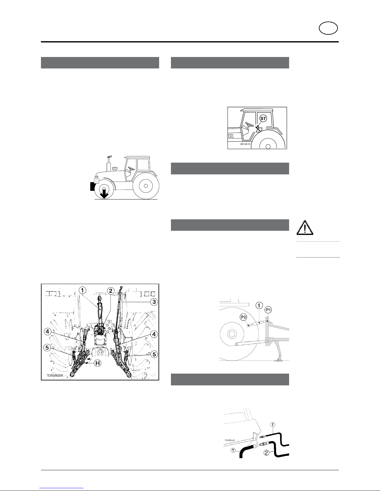
Lifting gear
- The left and right lifting struts (4) must be the same
length.
Adjust using adjuster (3).
-
If lifting struts (4) can be pinned at various positions
on the lower links, then select the back position (H). In
doing this, the tractor’s hydraulics will not be so greatly
overloaded.
-
Pin (2) upper link (1) in accordance with the manufacturer’s
specifications.
Setting-up for transportation
- Secure lower links with struts (5) so that attached
implement cannot swing out during transportation.
- The operating lever for the hydraulics must be secured
against lowering.
20%
Kg
Hydraulic control on the lifting gear
Control position:
For mounting and dismounting the implement and for
transportation.
The control position is the normal setting for the lifting
gear hydraulics.
T
h e m o u n t e d
implement remains at
the height (= position)
set by the servo-valve
(ST).
Preparing the cultivator
Mounting axle
Install correct mounting bar on tractor’s lifting gear
which corresponds to the connecting size (Category
II or III). See Spare Parts List also.
Connecting to tractor
- Switch tractor’s hydraulics to control position.
- Attach implement to lower link and secure with linch
pin.
Position upper link (1)
- Position upper link (1) so that the attachment point
(P1) on the implement is somewhat higher than the
attachment point (P2) on the tractor even during
operation.
C
onnecting hydraulic hoses
Double action control unit
- Connect pressure line (1) and oil-return pipe (2)
Safety
points:
see supplement-A1
Pkt. 8a. - 8h.)

GB
connecting to tractor
- 6 -
0700_GB-ANBAU_9765
- Make sure that swivel area is free and that nobody is
standing in the danger area.
- Move servo-valve (ST) to „rais“ position
The sideparts of the machine are swivelled into position
"Transport position".
-
Close hydraulic stop valve (A)
Conversion from transport to working position
- Open hydraulic stop valve (A)
- Make sure that swivel area is free and that nobody is
standing in the danger area.
-
Move servo-valve (ST) to „lower“ position
The sideparts of the machine are swivelled into position
"Working position".
Transport position SYNKRO
Safety Precaution!
Changing from
working to
transport position
is only to be
carried out on
even, firm ground.
Conversion from working to transport position
Working position SYNKRO
(A)
X = 4 m (Synkro 4003 K)
X = 5 m (Synkro 5003 K)
X = 6 m (Synkro 6003 K)

GB
connecting to tractor
- 7 -
0700_GB-ANBAU_9765
Driving on public roads
• Observe the official regulations of your country.
• Parts and attachment
- see spare parts list
• Travelling on open roads may only be carried out as
described in chapter "Transport position".
Total width of implement in the work position:
- more than 3m
Total width of implement in the transport
position:
see Technical Data
Parking, cleaning and winter storage of the
implement
• Observe the points in the chapter „Maintenance“!
Using additional implements.
Mount additional implements to the cultivator, such
as the drillbox (DB), according to the manufacturer’s
instructions.
• Do not overload the cultivator. If in doubt contact our
customer service office.
•
In addition, observe the power range limits of the tractor
in use.
- 8 -
0700_GB-EINsTELLUNGEN_9762
adjustments
DK
Setting for operation
1. The implement must be attached to the tractor in a horizontal
position, it should not hang to one side.
2. The front and rear tine rows must penetrate the ground at the
same depth (working depth).
The
frame should sit parallel to the ground surface as seen
longitudinally.
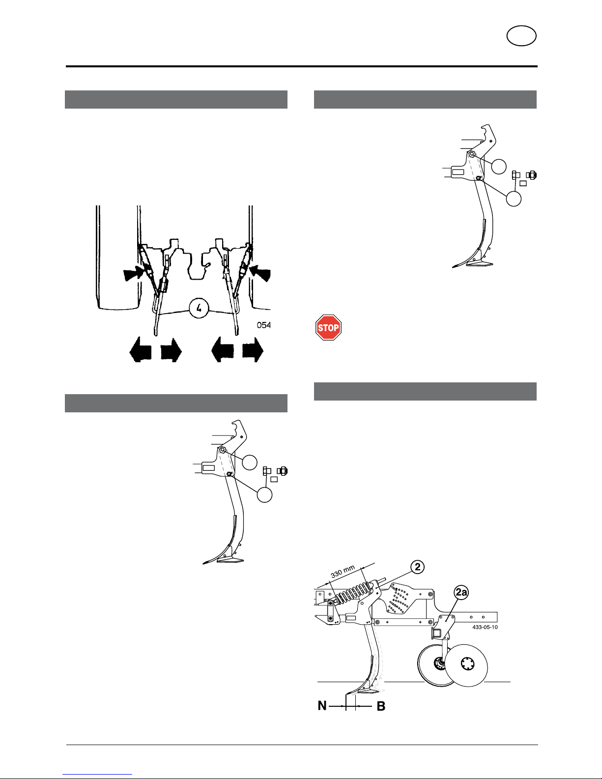
3.
Fix the lower link (4) in such a way that the machine cannot swing
out sideways.
Equipment variants and wearing parts
Rigid tines (basic equipment)
Spring-mounted tines (optional extra)
• Can be backfitted on all types
Backfitting kit (2 & 2a)
(see spare parts list)
-
Basic setting = 330 mm
Wearing parts
- are screwed to the tines and can therefore be replaced at little
cost.
Overloading
Shearing screws
Tines are secured with shearing
screws.
The shearing screw (pos. 7) breaks
when overloaded and the tine
swings upward.
-
Remove the shearing screw
remains.
-
Loosen hexagonal screw (6).
- Swing tine back to working
position.
-
Insert new shearing screw and
tighten both screws.
I
mportant!
Only use genuine shearing screws (see spare parts
list) of appropriate dimension and quality. Under no
circumstances use screws with a greater or lesser
strength.
344-05-14
7
6
Hollow discs
- serve to level out the ground surface evenly.
Setting the hollow discs
• This setting should suit the relevant operating conditions (type
of ground, speed and straw layer on the ground).
• The hollow discs are always set at the required working
depth.
Only fine adjustment is necessary
344-05-14
7
6
adjustments
- 9 -
0700_GB-EINsTELLUNGEN_9762
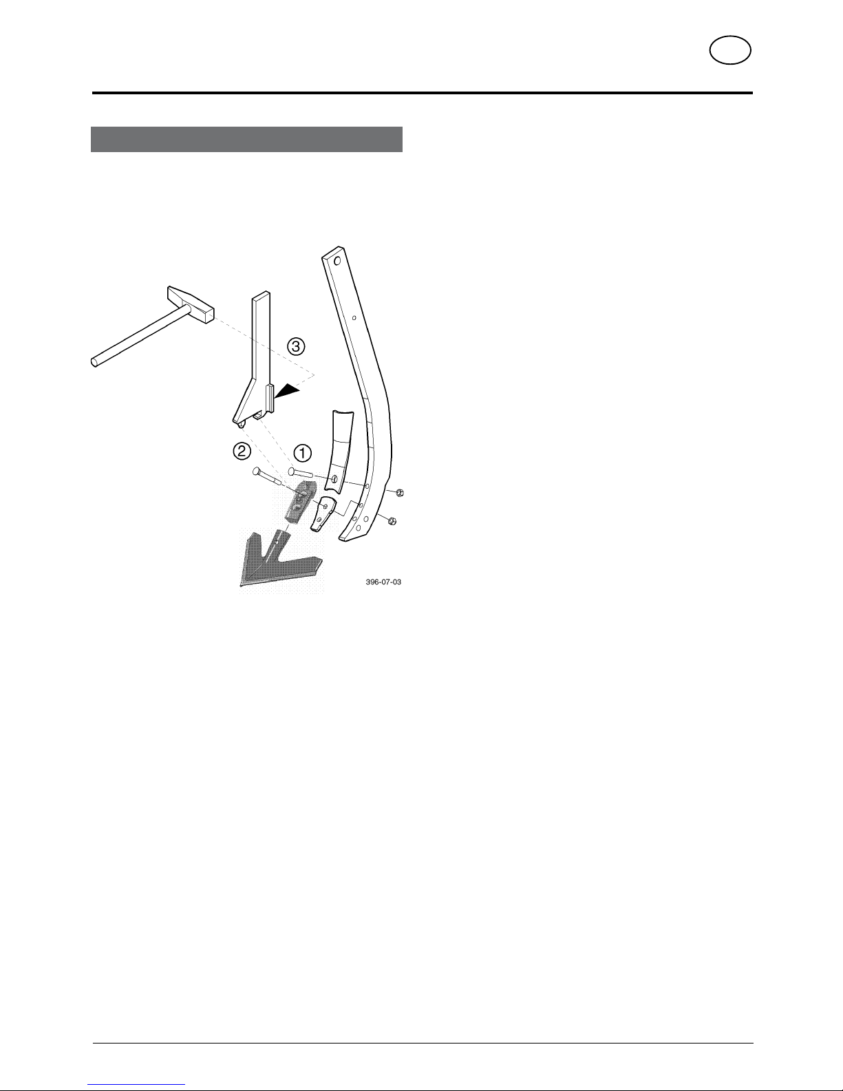
Share quick-change
1. Use change key
2. Press down on lock button
3. Release share with a hammer blow
DK

- 10 -
0700_GB-EINsATz_9762
use
GB
1. Check for proper attachment.
Before initial operation check all screws for tightness and retighten
if necessary.
2. Set required working depth.
Position both the support arms with pins (6) accordingly.
3. Swing hollow discs (left and right) into working position
(A)
Make sure pins (7) are inserted accordingly
4. Lower implement to the ground using tractor’s lifting
gear.
Drive a few metres into the working area then check the working
depth and the closing of the tine furrows.
5. If necessary, adapt tine angle to the operating conditions
(SK, EX).
Pos. B: Swivel the tines back (pos. B) if the required working
depth is not being obtained, e.g. with very heavy
ground.
Pos. N: Normal tine position.
SK
B
N
344-05-11
TD 34/95/20
5
2/3
1/3
Starting work
Basic setting for hollow discs: 1/3 of the total working depth.
O: Upper pins
To secure the trailer
U: Lower pins
For setting the working depth
Working depth difference from hole to hole of approx. 1.5 cm
Always change both pins!
 Loading...