

Pottinger PRIMO 350, PRIMO 450, PRIMO 400, PRIMO 500, PRIMO 630 Operator's Manual
...
GB
/PERATOR@SMANUAL
).3425#4)/.3&/202/$5#4$%,)6%290AGE
4RANSLATIONOFTHEORIGINAL/PERATING-ANUAL
PRIMO 350 (Type 1601 : + . . 01001)
PRIMO 400 (Type 1602 : + . . 01001)
PRIMO 450 (Type 1603 : + . . 01001)
PRIMO 500 (Type 1604 : + . . 01001)
PRIMO 630 (Type 1606 : + . . 01001)
PRIMO 800 (Type 1608 : + . . 01001)
.R 99 1602.GB.80I.0
Silage wagon
Ihre / Your / Votre • Masch.Nr. • Fgst.Ident.Nr.

GB
Dear Farmer
You have just made an excellent choice. Naturally we are very happy
and wish to congratulate you for having chosen Pöttinger. As your
agricultural partner, we offer you quality and efciency combined with
reliable servicing.
In order to assess the spare-parts demand for our agricultural machines
and to take these demands into consideration when developing new
machines, we would ask you to provide us with some details.
Furthermore, we will also be able to inform you of new developments.
Important information concerning Product
Liability.
According to the laws governing product liability, the manufacturer and dealer are obliged to hand the
operating manual to the customer at the time of sale, and to instruct them in the recommended operating,
safety, and maintenance regulations. Conrmation is necessary to prove that the machine and operating
manual have been handed over accordingly.
For this purpose,
document A is to be signed and sent to Pöttinger,
-
document B remains with the dealer supplying the machine,
-
- and the customer receives
In accordance with the laws of product liability, every farmer is an entrepreneur.
According to the laws of product liability, property damage is damage caused by a machine and not to
it. An excess of Euro 500 is provided for such a liabilioty.
In accordance with the laws of product liability, entrepreneurial property damages are excluded from
the liability.
Attention! Should the customer resell the machine at a later date, the operating manual must be given
to the new owner who must then be instructed in the recommended regulations referred to herein.
document C.
ALLG./BA SEITE 2 / 0000-GB

GB
INSTRUCTIONS FOR
PRODUCT DELIVERY
Dokument D
ALOIS PÖTTINGER Maschinenfabrik GmbH
A-4710 Grieskirchen
Tel. (07248) 600 -0
Telefax (07248) 600-511
GEBR. PÖTTINGER GMBH
D-86899 Landsberg/Lech, Spöttinger-Straße 24
Telefon (0 81 91) 92 99-111 / 112
Telefax (0 81 91) 92 99-188
According to the product liability please check the above mentioned items.
Please check. X
Machine checked according to delivery note. All
attached parts removed. All safety equipment, drive
shaft and operating devices at hand.
Function of electrical installation checked and
explained.
GEBR. PÖTTINGER GMBH
Servicezentrum
D-86899 Landsberg/Lech, Spöttinger-Straße 24
Telefon (0 81 91) 92 99-130 / 231
Telefax (0 81 91) 59 656
Hydraulic connection to tractor established and
Operation and maintenance of machine and/or
implement according to operating instructions
explained to the customer.
checked re. correct supply.
Hydraulic functions (drawbar, opening of rear gate, etc.)
demonstrated and explained.
Tyres checked re. correct pressure.
Handbrake and operating brake tested re. function.
Wheel nuts checked re. tightness.
Drive shaft cut to correct lenght.
Trial run carried out and no defects found.
Correct power-take-off speed indicated.
Mechanical functions (opening of rear gate, pivoting
of cutting mechanism out/in, etc.) demonstrated and
explained.
Removing and mounting of knives explained.
Electrical connection to tractor established and
checked re. correct supply (54 g connected). Note
references in operating manual.
Fitting to tractor carried out: hight of drawbar
adjusted, brake cable installed, hand brake lever
assembled in tractor cabin.
Functions explained during trial run.
Automatic on/off switch of loading mechanism
checked.
Pivoting in transporting and operating position
explained.
Information given re. optional extras.
Absolute need to read the operating manual indicated.
In order to prove that the machine and the operating manual have been properly delivered, a conrmation is necessary.
For this purpose please do the following:
- sign the document A and send it to the company Pöttinger
(in case of Landsberg equipment: to the company Landsberg)
- document B stays with the specialist factory delivering the machine.
- document C stays with the customer.
GB-0600 Dokum D Anhänger
- 3

Table of contents
WARNING SIGNS
CE sign ......................................................................6
Meaning of warning signs.......................................... 6
PUTTING INTO OPERATION
General safety tips for using the trailer ...................... 7
Before starting work .................................................. 8
FIRST-TIME CONNECTION TO TRACTOR
Hydraulic connection ................................................. 9
Connecting hydraulic lines ........................................ 9
To make the connection to the tractor .................... 10
Adjusting the hose container ................................... 10
Adjusting the trailer coupling .................................. 11
Vibration absorption 1) ............................................. 11
Setting the pivoting drawbar ................................... 11
Locking the trailing front axle .................................. 12
SUPPORTING WHEEL
Raising the jack stand by hand ............................... 13
Garaging the trailer .................................................. 13
PICK-UP
Height (M) = 430 mm ...............................................14
Setting of Pick-up pivoting area .............................. 14
CUTTER UNIT
Swivelling out upper cutter bar................................ 15
Swivelling out lower cutter bar ................................ 15
Swivelling out cutter bar hydraulically 1) .................16
Swinging cutter bar out to the side for
maintenance 1) ........................................................ 17
Removal and installation of a cutter ....................... 18
Safety points ............................................................ 18
Maintenance of cutters ............................................ 18
Disruption when swivelling out 3) ............................ 19
Alteration of gas container pressure ........................ 19
Maintenance ............................................................ 19
Adjusting the cutter beam ....................................... 20
TAILGATE
Safety mechanism .................................................. 21
Unloading using dispensing rollers.......................... 21
TAILGATE
Hydraulic opening and closing of the tail gate ........ 22
Safety device for closing of tailgate ........................ 22
Variations ................................................................. 23
Removal of regulating rollers ................................... 24
REGULATING ROLLERS
Scraper floor switch................................................. 25
Installing an oil pressure switch ............................... 25
TOP FRAME SECTION
Assembling the top frame section ........................... 26
DIRECT CONTROL - OPERATION
"DIRECT CONTROL" operating unit........................ 27
Carry out required hydraulic function ...................... 27
Loading functions .................................................... 28
Unloading functions ................................................. 29
Pivoting drawbar / Forage top frame ....................... 29
Automatic Loader- unloader 3) ................................ 30
Switching on automatic loader ................................ 30
Switching on automatic unloader ............................ 30
TABLE OF CONTENTS
POWER CONTROL - OPERATION
Configuration ........................................................... 31
Control panel ........................................................... 31
Button indication ..................................................... 31
Power control initial operation ................................. 32
WORK Menu loading functions ............................... 32
WORK menu unloading functions ........................... 34
SET functions .......................................................... 37
Diagnostic functions ................................................ 39
Cutting unit monitoring ............................................ 39
Sensor test .............................................................. 40
Adjusting machines ................................................. 40
Wireless Power Control - Control ............................ 41
Charging the AC ...................................................... 41
AC discharge ........................................................... 42
Radio contact range ................................................ 42
Pairing ...................................................................... 42
ISOBUS - TERMINAL
Operation ISO-terminal ............................................ 44
Start menu ............................................................... 45
Base setting menu ................................................... 45
Loading menu .......................................................... 45
Unloading menu ...................................................... 46
Unloading menu ...................................................... 47
Data menu ............................................................... 48
Config-menu ............................................................ 48
Set menu ................................................................. 49
TEST menu .............................................................. 51
Diagnostic menu ...................................................... 51
Joystick - Loader wagon configuration ................... 52
Setting the Joystick ................................................. 52
Uses of tractor data ................................................. 53
LOADING THE TRAILER
Loading process in general ..................................... 54
Adjusting the pick-up .............................................. 54
Starting the loading process.................................... 54
To observe during the loading process! ..................54
UNLOADING
Unloading the trailer ................................................ 55
Regulating equipment shut-off clutch (NS) ............. 55
Finishing the unloading process .............................. 55
MAINTENANCE
Safety point ............................................................. 56
General maintenance hints ...................................... 56
Cleaning of machine parts ....................................... 56
Parking in the ope .................................................... 56
Winter storage ......................................................... 56
Drive shafts .............................................................. 56
Hydraulic unit ........................................................... 56
Safety points ............................................................ 57
Gas container ..........................................................57
Overload clutch ....................................................... 57
Brake adjustment .................................................... 57
Opening the side protectors .................................... 57
Cutting unit .............................................................. 58
Transmission ............................................................ 59
Chains ...................................................................... 59
Press ........................................................................ 60
GB
Recommendations
for work safety
All points refering
to safety in this
manual are
indicated by this
sign.
0800_GB-Inhalt_1602
- 4 -

Once a year ............................................................. 60
Pick-up ....................................................................61
Adjusting measurement for end switch ................... 62
Oil pressure switch .................................................. 62
Changing the filter ...................................................62
Safeguarding the electrical unit ............................... 63
Maintaining electronic parts .................................... 63
Connecting the brake hoses ................................... 64
Service and maintenance on the air brake unit ....... 64
Release position on the brake unit .......................... 65
Parking the wagon ................................................... 65
AXLES AND AXLE UNITS
Lubrication points .................................................... 66
Maintenance work on wheels and brakes ............... 68
Maintenance work on the hydraulic running gear ...70
Maintenance work on the BOOGIE running gear .... 71
TROUBLESHOOTING
Troubleshooting ....................................................... 73
Disruptions and remedies to power failure ............. 74
TECHNICAL DATA
Technical data .......................................................... 76
Position of Vehicle Identification Plate ....................76
Optional equipment ................................................. 76
The defined use of the trailer ................................... 77
Correct loading ........................................................ 77
Air pressure ..............................................................78
SUPPLEMENT
Recommendations for work safety ......................... 81
Driveshaft ................................................................. 82
Lubrication chart ...................................................... 84
Lubricants ................................................................ 86
Emergency brake valve ........................................... 88
Internal hydraulic supply for cross conveyor belt .... 90
Oil tank..................................................................... 90
Pump ....................................................................... 90
Hydraulics plan (up to 2006 model) ......................... 91
Hydraulics plan (from 2006 model) .......................... 92
Job calculator layout plan ....................................... 93
Job calculator layout plan - PWM ........................... 94
Hydraulic plan .......................................................... 95
Connection diagram ................................................ 96
TABLE OF CONTENTS
GB
0800_GB-Inhalt_1602
- 5 -

WARNING SIGNS
495.163
CE sign
The CE sign, which is affixed by the manufacturer, indicates outwardly that this machine
conforms to the engineering guideline regulations and the other relevant EU guidelines.
EU Declaration of Conformity (see Supplement).
By signing the EU Declaration of Conformity, the manufacturer declares that the machine
being brought into service complies with all relevant safety and health requirements.
Meaning of warning signs
GB
Recommendations
for work safety!
All points referring
to satety in this
manual are
indicated by this
sign.
Turn engine off when adjustment,
service and repair work is to be
done.
Wait until all machine components
have stopped completely before
touching them.
Don't step on loading platform if PTO
is connected to tractor and Engine
is running.
Never reach into the crushing danger
area as long as parts may move.
Stay clear of gate swinging area while
tractor engine is running. Access
only allowed when safety lock is
applied.
Never reach into the pick-up area as
long as tractor engine is running with
PTO connected.
0400_GB-Warnbilder_548
Danger - stay clear of rotating
machine parts.
- 6 -
Warning against damage
• the bolts on the left and right
hand trailer sides must always
be equally positioned otherwise
the tailgate and swivel sections
will be damaged;
therefore
- always check before opening the
tailgate hydraulically
PUTTING INTO OPERATION
20%
Kg
General safety tips for using the trailer
GB
Tips for travelling with the trailer
The handling of the tractor is influenced by the trailer
coupled to it.
• Danger of tipping exists when working on slopes.
• The driving must be adapted to the corresponding
terrain and ground conditions.
• Maximum speeds must be observed (depending
on implement’s equipment)
• The towing vehicle is to be sufficiently equiped
with weights at the front or at the rear in order to
guarantee the steering and braking capacity (a
minimum of 20% of the vehicle's tare weight on
the front axle).
Tips for coupling and uncoupling the
trailer
• Danger of injury exists when coupling the implement
to the tractor!
• As long as the tractor is moving backwards, do not
step between it and the trailer when coupling.
• Nobody is to stand between the tractor and trailer
without the vehicles being secured against rolling
with the parking brake and/or wheel chocks.
• Drive shaft connection or disconnection is only to
be undertaken when the motor has stopped.
• When connecting cardan shaft ensure it is properly
locked into place
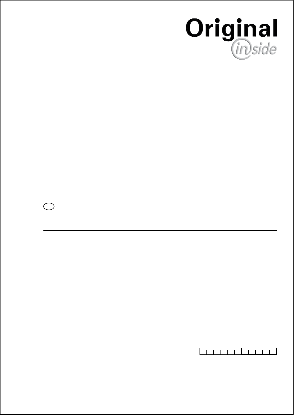
Parking the implement
• When the implement ist parked, either remove the
driveshaft and store it, or secure it with a chain.
Do not use retaining chain (H) for this.
Take note!
Observe also
the tips in the
respective
chapters and in
the supplement
to this operating
manual.
• Be aware of implement’s height (especially with low
thoroughfares, bridges, overhead lines, etc.)
• The transport of persons on the machine is not
permitted.
Travelling on roads
• Observe the road rules.
• The tailgate must be closed when travelling on public
roads. Lighting devices must be fitted vertically to
the road.
Only use the trailer according to regulations!
Regulations for Use: See chapter "Technical Data".
• The trailer's load limits (permitted axle load, support
load, total weight) may not be exceeded. The relevant
details are located on the right side of the trailer.
• In addition, observe the power limits of the tractor
being used.
0700_GB-INBETRIEBNAHME_511
- 7 -

Before starting work
a. Before commencing work, the operator must be aware
of all operating devices and functions. The learning
of these is too late after having already commenced
operation!
b. The vehicle is to be tested for traffic and operating
safety before each operation.
c. The danger of being crushed or cut exists in the Pick-
up, cutting unit, tailgate and upper extension areas.
All persons must be shown out of these areas before
activating hydraulic equipment and turning on the
drive.
d. Before driving the vehicle, the driver must ensure that
nobody will be endangered and that no obstructions
are present. If the driver is unable to see and have an
overall view of the roadway directly behind the trailer,
he must be guided by somebody while reversing.
e. Observe the safety tips which are attached to the trailer.
An explanation of what the individual graphic warning
symbols mean can be found on page 5.
f. Observe also the tips in the respective chapters and
in the supplement to this operating manual.
PUTTING INTO OPERATION
Checking before operation
1. Check that all safety equipment (coverings, casings,
etc.) are in proper order and fitted in position on the
trailer.
2. Grease the trailer in accordance with the lubrication
chart. Check the gearing for tightness and the oil
level.
3. Check that tyres have the correct air pressure.
4. Check that wheel nuts are sitting firmly.
5. Ensure the correct p.t.o.-r.p.m..
6. Make the electrical connections to the tractor and
check that they are correct. Take note of the tips in
the operating manual!
7. Carry out the following adaptions:
• Drawbar height
• Laying of brake cable
• Install hand brake lever in the tractor cabin.
8. Secure trailer using only the fixtures provided.
9. Cut drive shaft to the correct length and check the
function of the overload safety (see supplement).
10. Check the electronic unit function.
11. Connect hydraulic lines to tractor.
• Check hydraulic hoses for damage and wear.
• Ensure the correct connection.
12. All swivelling parts (tailgate, adjusting lever, etc.) must
be secured against dangerous position changes.
13. Check parking brake and service brake functions.
GB
Instruction!
The following tips
should make
the trailer's
operation easier
for you. Detailled
information for
individual points
can be found in
the respective
chapters in this
operating manual.
0700_GB-INBETRIEBNAHME_511
- 8 -
7b
001-01-23
P
T
LS
7
7a
FIRST-TIME CONNECTION TO TRACTOR
GB
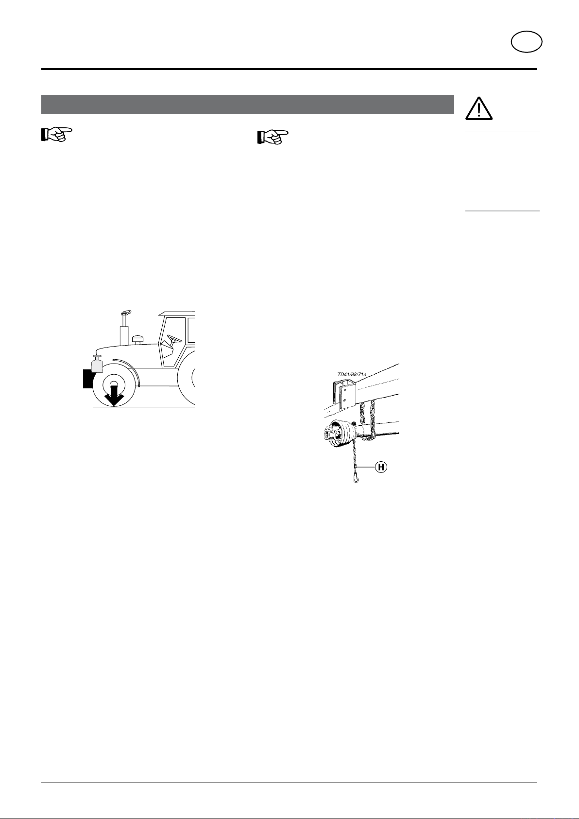
Hydraulic connection
Single-action control unit
Should the tractor only have a single-action servo-valve,
then it is absolutely necessary to have an oil-return pipe
(T) fitted by a specialist.
- Connect pressure hose (1) to the single-action control
unit. Couple the oil-return hose (2) (with the greater
diameter) to the tractor’s oil-return system.
Double-action control unit
- Connect pressure line (1) and oil-return pipe (2) (pipe
with the greater diameter is the oil-return pipe).
LS Line (Optional extra)
- Connect load sensing line to LS connection on the
tractor.
Take care with tractors with a closed
hydraulic and LS system
JOHN-DEERE, CASE - MAXXUM, CASE - MAGNUM,
FORD SERIE 40 SLE
Before coupling, the screw (7) on the hydraulic block is
to be screwed completely in (7b).
Connecting hydraulic lines
- Turn p.t.o. off before connecting
- Put lever (ST) on the control unit into the floating position
(neutral position).
- Take care that snap-lock couplers are clean.
Standard position with an open
hydraulic system
The position of the screw (7) is set in the factory
(7a).
Warning!
If this is not done then the overload valve on the tractor’s
hydraulics is continually in use and excessive warming
of the oil will occur!
Note!
If oil should
become warm
during operation
then a single-
action control
unit should be
connected (see
above).
Note!
An unpressurized
oil return must be
guaranteed on the
tractor.
Note!
The tractor’s
hydraulic
pressure must not
exceed maximum
205 bar.
0701_GB-Erstanbau_5543
7a
Standard position with an open hydraulic
system
7b
Take care with tractors with a closed
hydraulic and LS system
LS = Load sensing
- 9 -
FIRST-TIME CONNECTION TO TRACTOR
GB
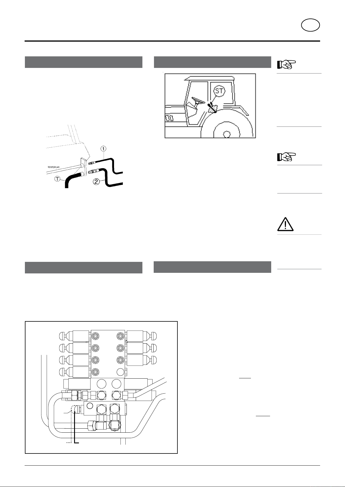
To make the connection to the tractor
Operation:
- Connect the 3-channel plug to the DIN 9680 socket
on the tractor
Lighting:
- Connect 7-channel plug to tractor
- Check that lighting is functioning on wagon
For tractors with ISO Bus control
- Connect 9-channel ISO plug to ISO Bus socket on the
tractor
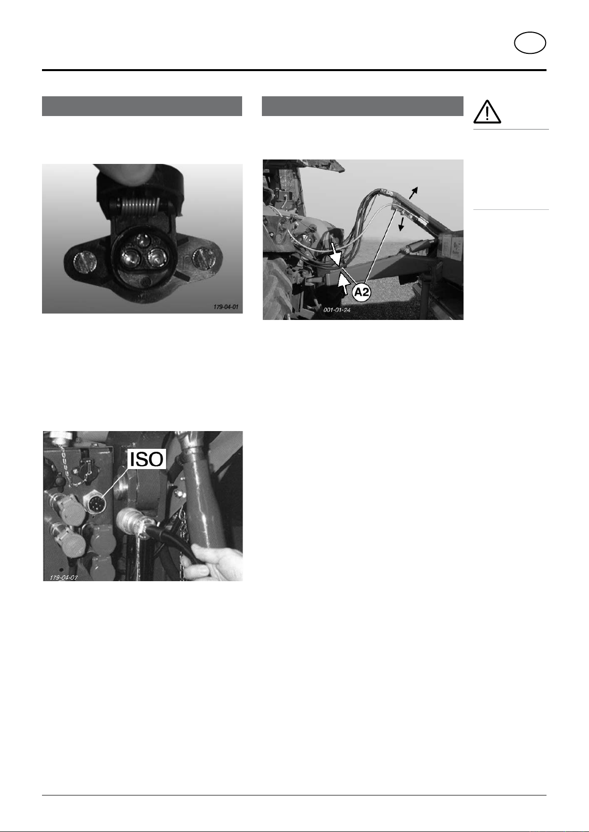
Adjusting the hose container
- Adjust the hose container in such a way that there is
sufficient distance between the hydraulic lines and the
drawbar (A2).
Important!
Before putting
the tractor into
operation check
vehicle safety
(lights, brake
unit, protective
covering, .....).
0701_GB-Erstanbau_5543
- 10 -
FIRST-TIME CONNECTION TO TRACTOR
A
001-01-26
136-07-01
G
K
1 - 3 cm
A1
001-01-25
GB
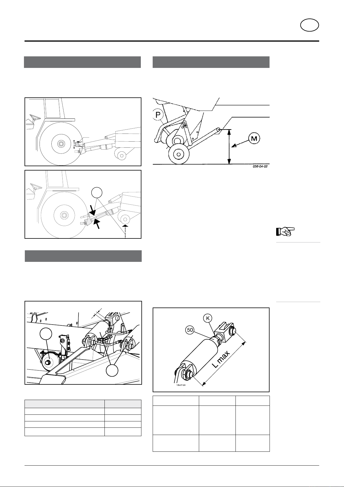
Adjusting the trailer coupling
- Extend the drawbar coupling (A) so that there is sufficient
gap between drive shaft and drawbar of attached trailer,
especially in the event of pivoting (A1).
Vibration absorption 1)
Important!
To ensure that vibration absorption functions properly:
- cylinders (K) must not be completely inserted when
driving on roads
- extend cylinders (K) approx. 1 – 3 cm.
Setting the pivoting drawbar
To allow pick-up to work properly, the height (H ) of coupled
trailer must be correctly set (pick-up pivoting area).
- Setting measurement (M) see chapter “Pick-up”
Starting position:
- Couple trailer to tractor
- Both hydraulic cylinder pistons must be completely
inserted.
Adjustment process:
- Loosen lock nut (K) on the threaded spindle
- By twisting the cylinder piston (50), screw the threaded
spindle in or out until the height (M) is achieved.
Do not exceed maximum regulating limits (see table
below for L max)
- Adjustment of both hydraulic cylinders must take place
alternately
- Both hydraulic cylinders must be set at the same
length
- Retighten lock nut (K)
Note!
Damage can
occur if threaded
spindle is
unscrewed too
far. Observe
maximum
measurement
according to
table!
Pressure in the gas container (G):
Type Fill pressure
PRIMO, FARO
EUROPROFI
TORRO, JUMBO (3 to-Anhängung)
JUMBO (
2 to-mounting)
• To alter pressure – see chapter “MAINTENANCE”
1) Series factory tting for JUMBO, TORRO
Optional extra for EUROPROFI, FARO, PRIMO
0701_GB-Erstanbau_5543
50 bar
70 bar
80 bar
100 bar
Type Parts number L max
PRIMO, FARO
EUROPROFI,
TORRO, JUMBO
(2 to-mounting)
JUMBO 3t
(3 to-mountng)
- 11 -
442.240 555 mm
442.313 615 mm

FIRST-TIME CONNECTION TO TRACTOR
137-06-02
137-06-03
137-06-04
Locking the trailing front axle
GB
• The trailing front axle is operated differently depending
on tractor and wagon equipment
Variant 1
Attention!
The trailing front
axle must always
be locked during
fast road travel
with a full wagon!!!
Variant 2
- For tractors without Load sensing system:
- connect additional hydraulic line to tractor
- open or close the trailing front axle using control
(ST)
Attention!
The trailing front axle must be locked
- when travelling straight ahead quickly at 30 km/h or more
- with unpaved surfaces
- in sloped areas
- with load on the front axle through pivoting drawbar usage
- when travelling over a drive-in silo
- when lateral traction of the unguided axle is no longer sufficient
For tractors with Load sensing system:
- hydraulic line is connected to hydraulic block
- operation takes place using “POWER CONTROL”
unit or “Isobus terminal”
(see description of Control)
0700_GB-Lenkachssperre_5543
- 12 -

SUPPORTING WHEEL
GB
Raising the jack stand by hand
- Couple the trailer to tractor
- Take load off jackstand by using pivoting drawbar.
- Pull out locking bolt (1), swing jack stand up and lock
again.
- Make sure bolt is properly locked in (1).
Garaging the trailer
• Park the trailer on firm, level ground.
If the ground is soft then the area where the jack
stand is to stand must be appropriately increased
using a suitable aid (e.g. wooden board).
- Raise the trailer a little using the pivoting drawbar.
- Pull out locking bolt (1), swing jack stand down and
lock again.
- Make sure bolt (1) is properly locked in!
- Lower the trailer using the pivoting drawbar.
- Uncouple hydraulic- and electric lines and detach
trailer.
Attention!
Only garage an
empty trailer on
the jack stand
and chock the
wheels to prevent
rolling.
0500_GB-Stützfuß_1612
- 13 -
PICK-UP
GB
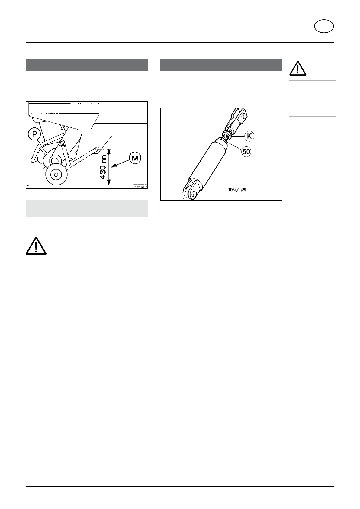
Height (M) = 430 mm
To allow pick-up to work properly, the height (H ) of coupled
trailer must be correctly set (pick-up pivoting area).
Note: Where the floor is uneven, reduce the measurement
by 1 cm (M = 420 mm)
The deflector (P) also serves as accident
protection and must not be removed during
operation.
Setting of Pick-up pivoting area
(Height (M) = 430 mm)
- Couple trailer to tractor
- Both hydraulic cylinder pistons must be completely
inserted.
Adjustment of both hydraulic cylinders must
take place alternately
- Loosen lock nut (K) on the threaded spindle
- By twisting the cylinder piston (50), screw the threaded
spindle in or out until the height (M) is achieved.
- Retighten lock nut (K)
Take care!
Be aware of
crushing points
when moving the
Pick-up down or
up!
0701_GB-Pick-up_1602
- 14 -
CUTTER UNIT
GB
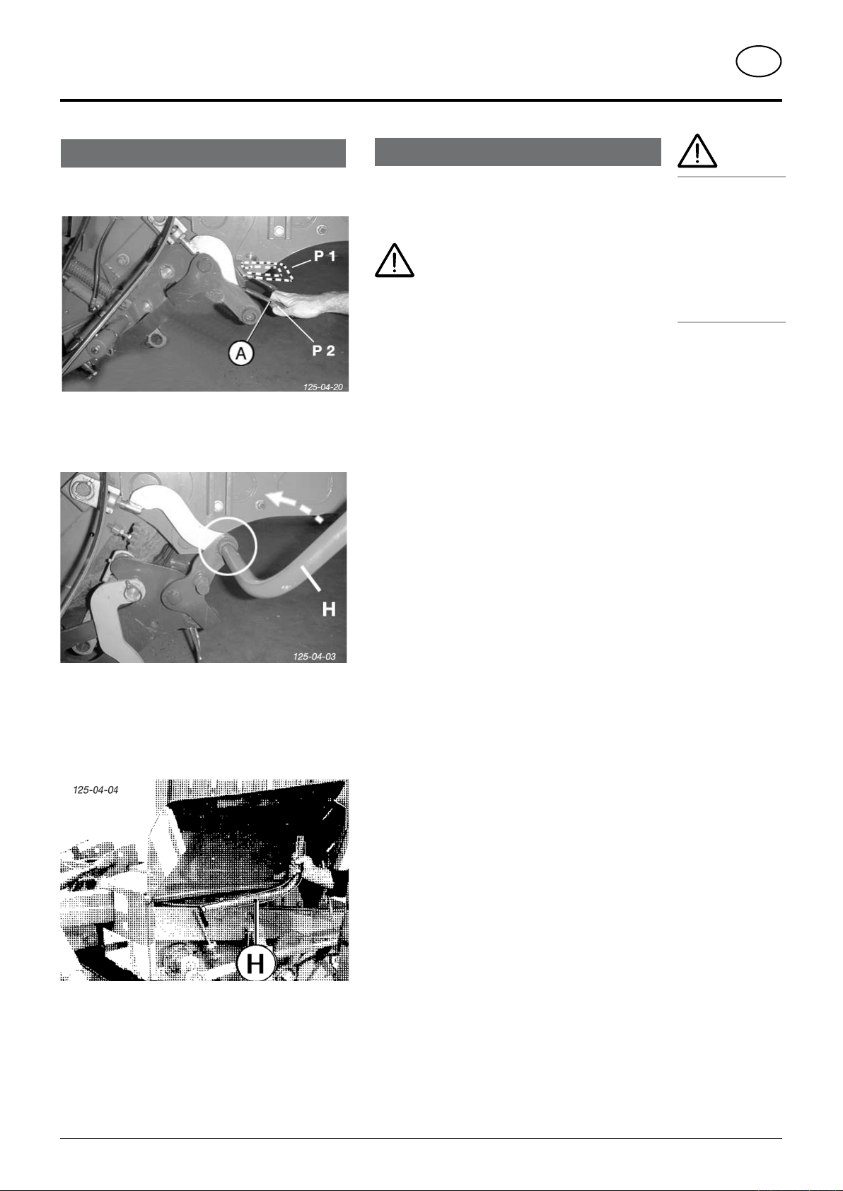
Swivelling out upper cutter bar
(Mechanically)
- Move stirrup grip (A) to position P2
- Insert lever (H) into hexagonal socket on cutter bar.
- Move lever forward.
- Cutter bar swivels out to central position.
- Lever (H) is located underneath front collapsible side
guard.
Swivelling out lower cutter bar
• When only one cutter bar is needed for mowing,
the lower cutter bar can be swivelled out using the
accoompanying lever (H).
Attention!
Do not reach into swivel range of cutter
bar when swivelling in / out.
Important checks to be carried out on the cutter
beam before each operation
- left and right hand pins locked
- for wear on the cutters
- for dirt on the cutter overload fuse
- for adequate ground clearance
* Vehicle must not be driven whilst cutter beam is in fully
extended position
General information
To facilitate maintenance work on the cutting unit, the
cutter beam can be swung on to the left-hand side of the
vehicle (Optional equipment).
All cutters are then accessible:
- for grinding the cutters
- for installing or removing the cutters
- for cleaning
Attention!
Increased chances
of injury with all
work carried out
on cutter bar,
particularly with
swinging cutter
bar in from the
side or when
swivelling it up!
0500_GB-Schneidwerk_563
- 15 -

CUTTER UNIT
GB
Swivelling out cutter bar hydraulically
- Move stirrup grip (A) to position P2
Variant with Select-Control operating unit
1)
- Swivel cutter bar out with hydraulic cylinder (Z)
- Bar locks in central position
Variant with Direct-Control operating unit
Attention!
Cutter bar is
swivelled out and
in hydraulically.
Beware of
crushing in stirrup
grip area!
3
1. Press cutting unit button (3)
- The integrated control lamp (LED) lights up
2. Activate control valve on tractor
- Cutter bar swivels out
3. Deactivate hydraulic function
- Press button, integrated control lamp (LED) goes
out
For safety reasons always deactivate the
preselected function
See chapter “Select-Control Preselection”
also
3
4
1. Swing cutting unit in
Press (3) button and hold (= touch function)
- The control lamp (LED), integrated into the key,
glows red.
- Cutting unit swivels in under pressure
2. Swing cutting unit out
Press (4) button and hold (= touch function)
- The control lamp (LED), integrated into the key,
glows red.
- cutting mechanism is swivelled out
The cutting sensor available (option) signals the LED
(constant light) of the swivelled out state.
Signal tone when Pick-up is lowered
See chapter “Direct-Control Operation” also
0500_GB-Schneidwerk_563
- 16 -
1)
Optional equipment
CUTTER UNIT
GB
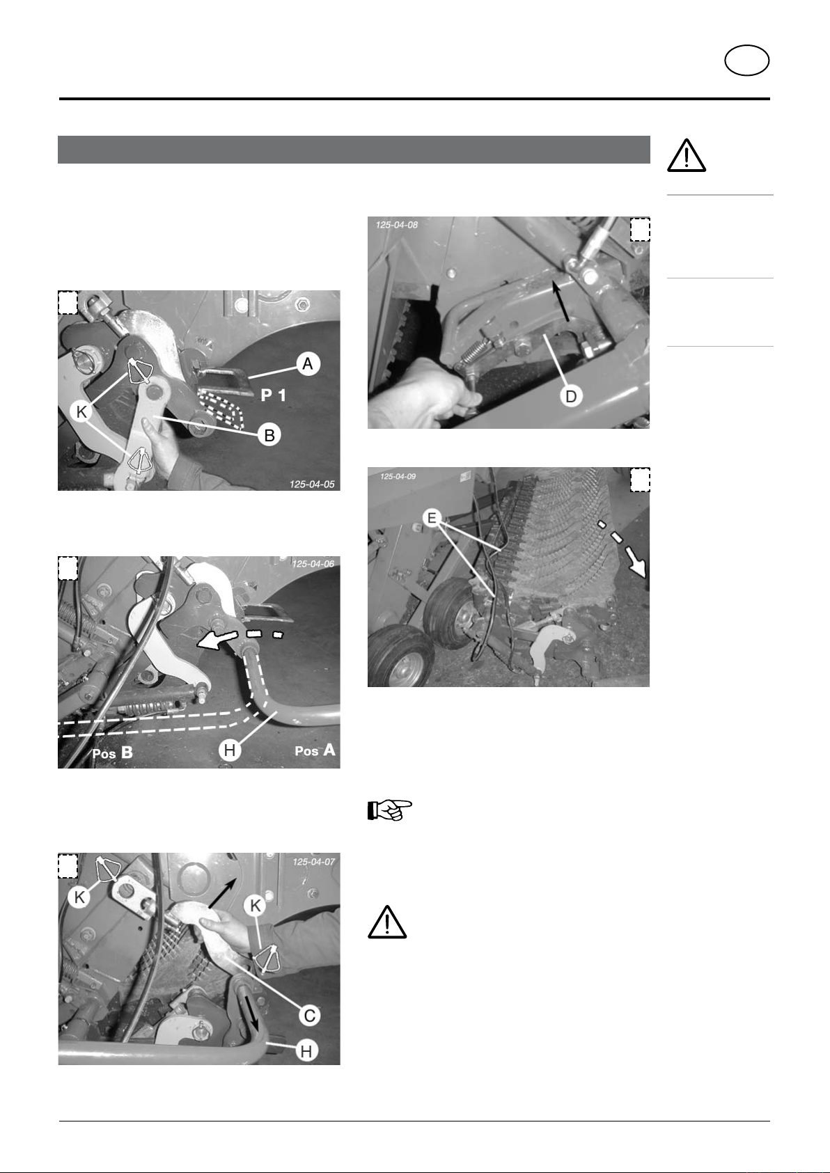
Swinging cutter bar out to the side for maintenance
- Swivel cutter bar completely in
1. Lock stirrup grip (A) in position P1.
- Cutter bar is not locked in central position.
- Remove linch pin (K)
- Remove bracket (B)
1
2. Move lever (H) forward (pos B)
- Swivel cutter bar completely out
2)
2)
1)
4. Release lock (D)
- on left and right vehicle sides
5. Swing cutter bar out to side
• Turn engine off
4
when adjustment,
service and repair
machine without
5
Safety advice!
work is to be
done.
• Do not work
under the
safe support.
2
3. Remove linch pin (K) and take off left and right brackets
( C )
- Remove lever (H)
3
- Observe hydraulic lines (E) when swinging cutter bar
out to the side
Assembling the cutter bar occurs in reverse
order
Attention!
Increased chances of injury with all work
carried out on cutter bar, particularly with
swinging cutter bar in from the side or
when swivelling it up!
1)
Optional equipment - Only for variant with hydraulic cutting unit
0500_GB-Schneidwerk_563
- 17 -
CUTTER UNIT
GB
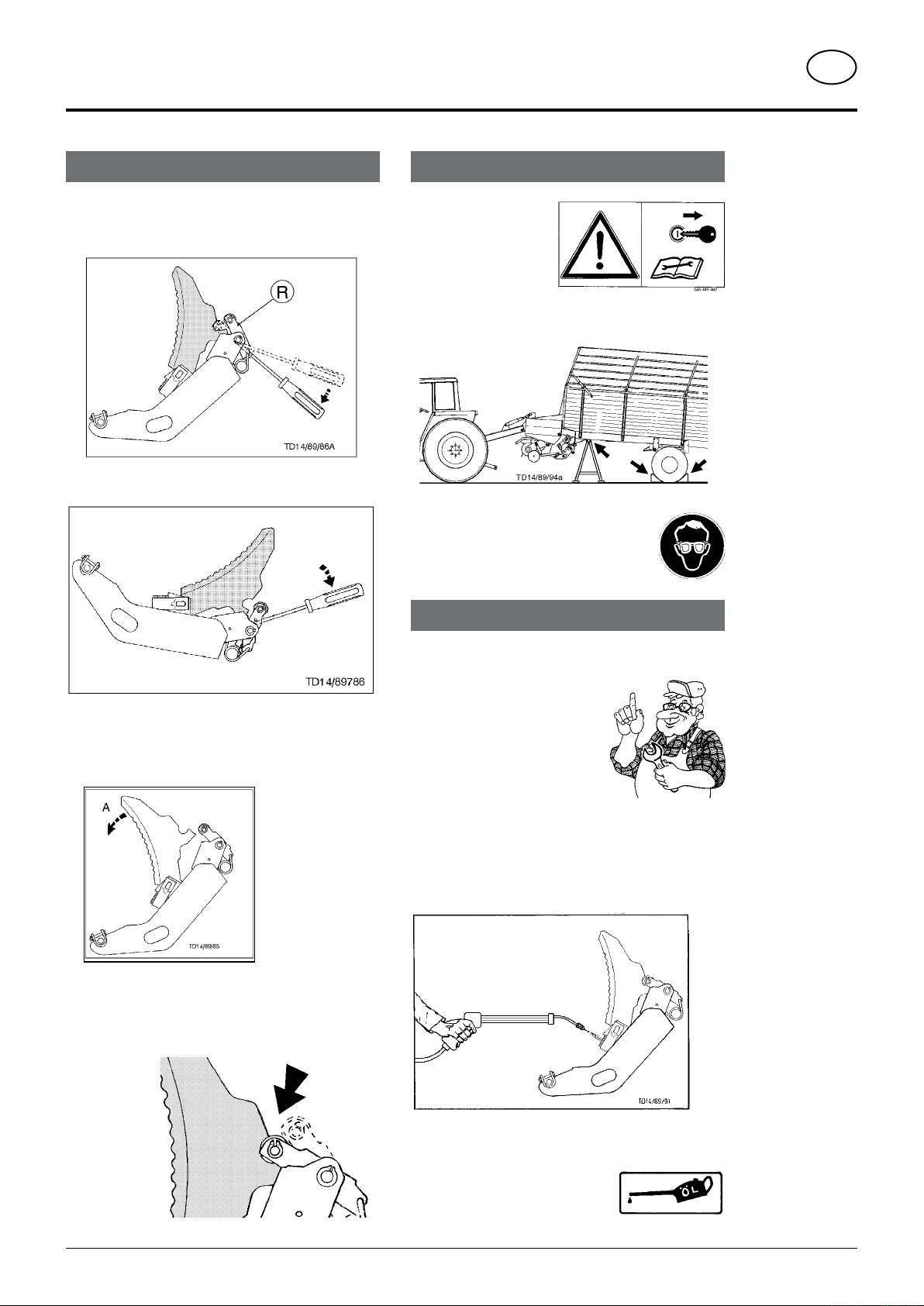
Removal and installation of a cutter
Removing a cutter from a swivelled out cutter bar.
1. Pull catch lever (R) down using screwdriver.
Removing a cutter from a swivelled up cutter bar.
Safety points
• Turn engine off when
adjustment, service
and repair work is to
be done.
• Do not work under the machine without safe
support.
• Wear protective glasses.
Maintenance of cutters
2. Swivel cutter up (position A) and remove by pulling
backwards.
Cutter installation
- Take care that catch lever caster rests properly in cutter
recess.
Well ground cutters save energy and provide good cutting
quality.
Caution!
Only grind the smooth
side of the cutter
Sensible g rinding
wi t h o ut he a ti n g
(tarnishing) the cutter
guarantees a long life.
Cutter safeguard
Regularly cleaning is recommended to guarantee the
perfect function of the cutter safeguard.
0500_GB-Schneidwerk_563
• Clean pressure springs with high pressure cleaner.
• Oil cutter and safeguard element
before winter storage!
- 18 -
CUTTER UNIT
GB
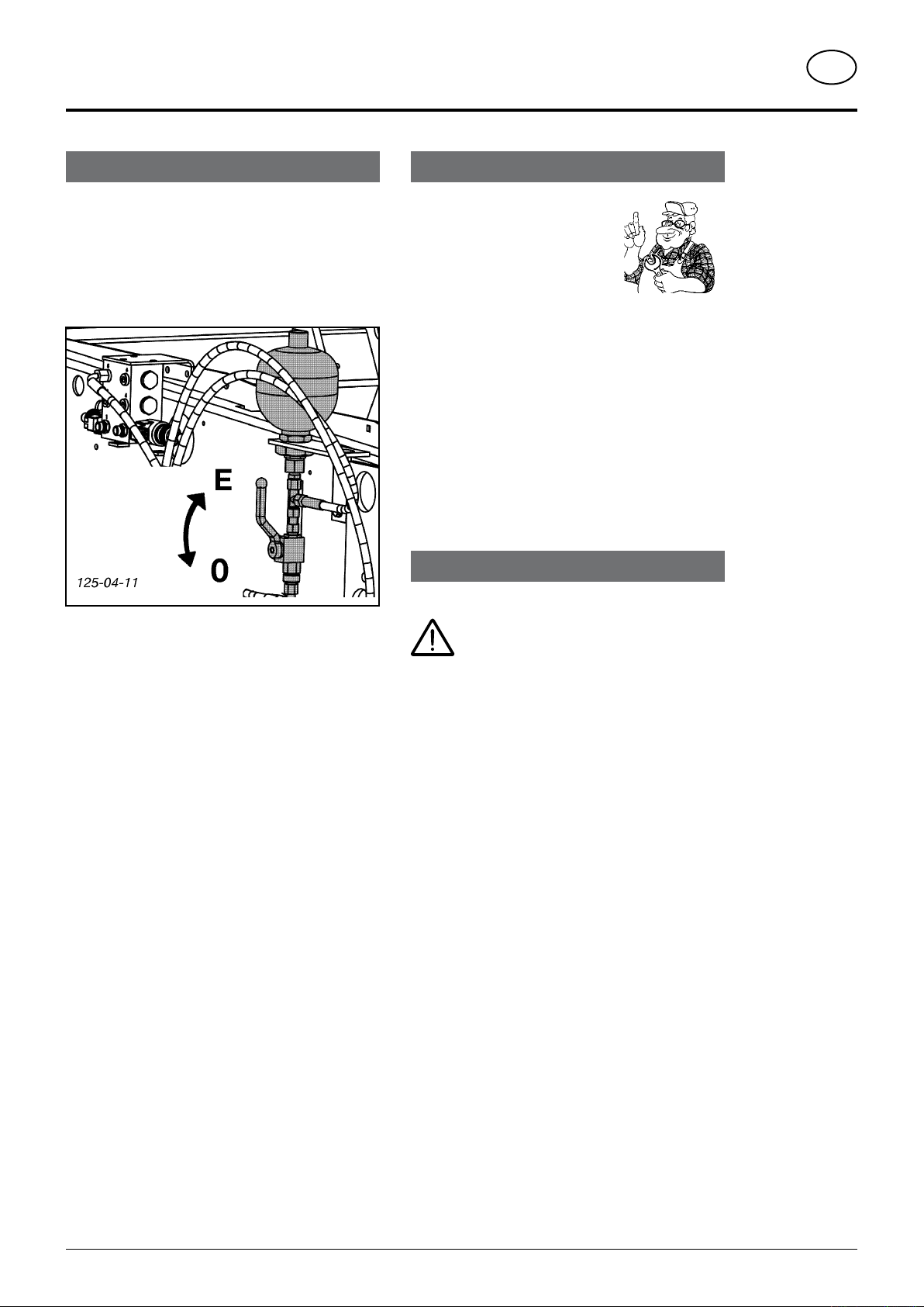
Disruption when swivelling out
- Remove foreign body from swivel range.
• When cutter bars do not swivel in properly it may be
due to pressure loss in cutting unit hydraulics.
• Remedy by hydraulically filling the reservoir
- Move lever to position "E" on 3-way valve.
- Actuate servo-valve.
3)
Alteration of gas container pressure
• This work may only be carried
out by customer service or a
specialist.
• In order to reduce or increase the
pressure in the gas container a
special filling and checking device
is necessary.
Note
• According to manufacturer's information all gas
containers have a slight pressure drop after a certain
amount of time.
• The gas loss (nitrogen) amounts to 2-3 % per year.
• After 4-5 years it is recommended that container
pressure be checked and if necessary corrected.
Maintenance
- Cutter bars are swivelled out hydraulically.
- Leave servo-valve (ST) in the press position for a few
seconds while moving the lever on the 3-way valve to
position "0".
• If obstruction cannot be removed then check gas fill
pressure (100 bar nitrogen) in hydroreservoir.
Beware!
No welding, soldering or mechanical
works of any kind may be carried out
on the container.
• Hydraulic oil change according to tractor manual.
• Before welding on trailer disconnect all plugs from
tractor and disconnect trailer.
3)
Only for variant with Select-Control operation
0500_GB-Schneidwerk_563
- 19 -
125-04-29
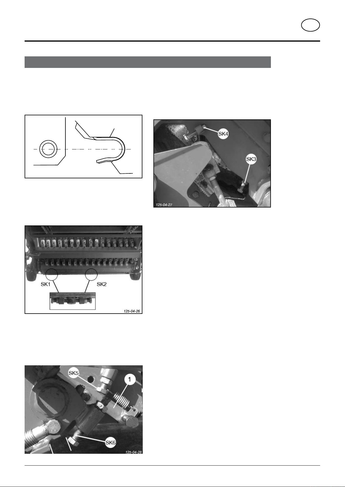
Adjusting the cutter beam
CUTTER UNIT
GB
Set cutter beam vertically
- When the cutter frame is swung back in, the setting
should be such, that it enables the frame tubing to fit
into the opening on the moulded frame without any
difficulty (see sketch).
Adjustment on the underside of the cutter beam
- Firstly, adjust the height with screws (SK1)
- Then adjust horizontally with screws (SK2)
- Repeat procedure if necessary
Secure the cutter beams against unintentional
swinging out
The screws (SK3 and SK4) prevent the cutter beams
from swinging out during operation
- Screw (SK4) for the upper cutter bar
- Screw (SK3) for the lower cutter bar
Setting
- Loosen locking nut
- Turn the screw far enough to place light pressure
on the cutter beam
- Secure screw with locking nut
Adjusting screws for lower cutter beam
- The catch hook (1) is adjusted with screws (SK5)
- The limit stop in the lower position of the cutter beam
is adjusted with (SK6)
0500_GB-Schneidwerk_563
- 20 -
TAILGATE
GB
Safety mechanism
The tailgate’s own weight is used to lower it to position
C. No other pressure is used.
Only when in this position (C) is the hydraulic function activated through switch (56) and the tailgate is
closed under pressure.
Unloading using dispensing rollers
Variations
1. Standard dispensing
• Rear steel section fixed to swivel frame
- secure with linch pin (F) (left and right)
2. Fine dispensing
• Rear steel section fixed to side walls
- secure with spring pin (F) (left and right)
The forage falls evenly distributed to the ground as with
standard dispensing
Attention!
Nobody should
be within the
swinging range
of the tail gate
when opening and
closing!
Do not stand
underneath the
raised tail gate!
Travelling on public
roads must only
be undertaken
with the tailgate
closed!
With all of these switching procedures, be
alert to the danger distances!
An example:
Danger of injury arises if a person stands
at the rear of the trailer and somebody in
the tractor cabin activates a switching
function (opening the tailgate, switch on
the driving gear, ...).
0400_GB-Rückwand_5543
Warning against damage
• The bolts on the left and right hand trailer sides
must always be equally positioned otherwise the
tailgate and swivel sections will be damaged
therefore
- alway s check befo re
opening the t a i l g a t e
hydraulically
- 21 -
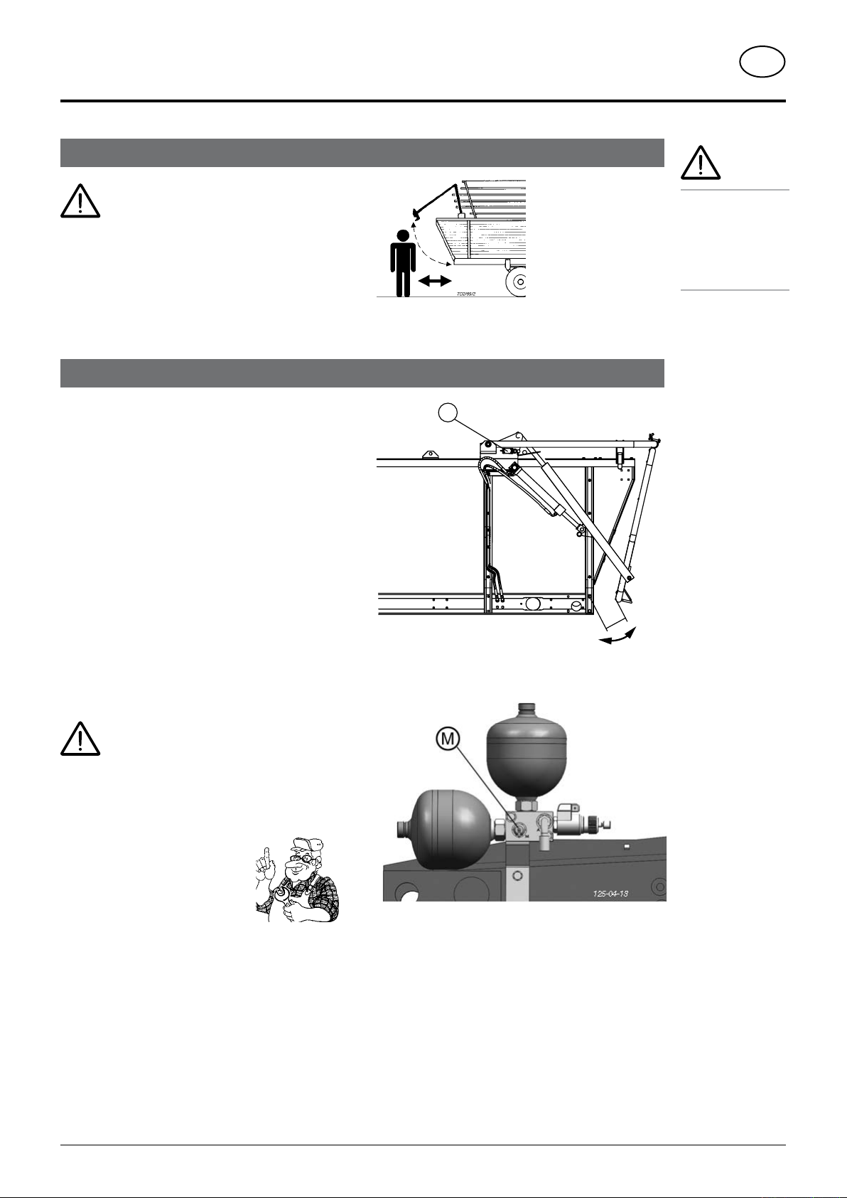
Hydraulic opening and closing of the tail gate
G
C
56
125-04-17
ca
.
100
m
m
TAILGATE
GB
Do not stand underneath the raised tail
gate!
- Opening and closing is effected hydraulically from the
tractor seat.
- Locking takes place automatically.
- Tailgate must be closed when driving on the road.
Safety device for closing of tailgate
Variant with DIRECT-CONTROL operation
The tailgate’s own weight is used to lower it to position
C. No other pressure is used.
Only when in this position (C) is the hydraulic function
activated through switch (56) and the tailgate is closed
under pressure.
For opera tion s ee chap ter “D IRECT-CO NTROL
operation”
Attention!
Nobody should
be within the
swinging range
of the tail gate
when opening and
closing!
Variant with Select-Control operation
Attention!
Compressed air is used to lower and close
the tailgate
- Danger of crushing when closing
• In order to reduce or increase the
pressure in the gas container a
special filling and checking device
is necessary (M).
Pressure in the gas container: 25
bar Nitrogen (N).
• This work may only be carried out by customer service
or a specialist.
See also “Alter pressure in gas container “ in chapter
“CUTTER UNIT”
Fo r operation see chapter “ SELE CT-CONTROL
Preselection”
0500_GB-Rückwand_563
- 22 -
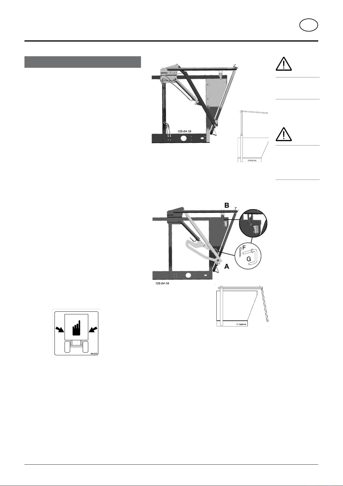
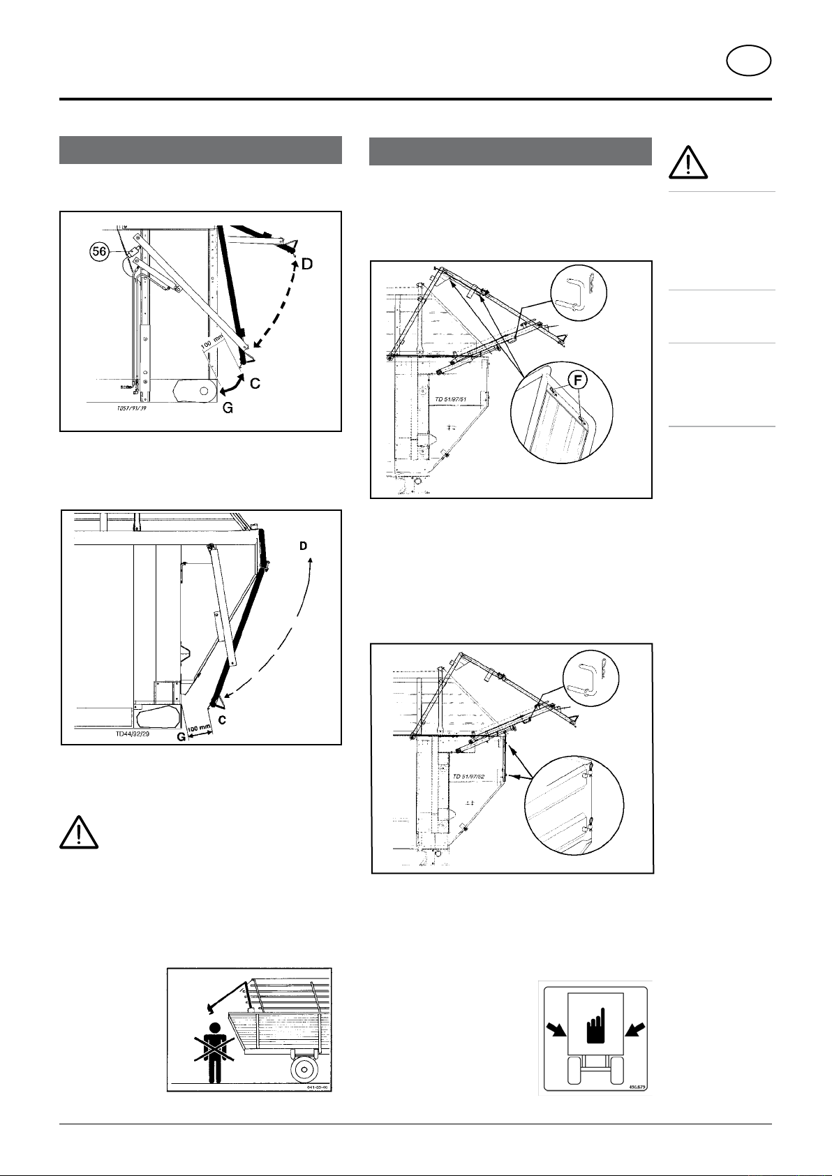
Variations
Rigid tailgate strut
- The tail gate and the tubular frame swing all the way
to the top when opening.
For operation see
- Select-control preselection or
- Direct-control operation
TAILGATE
underneath the
raised tail gate!
Travelling on public
roads must only
be undertaken
with the tailgate
GB
Attention!
Do not stand
Attention!
closed!
Adjustable tailgate strut
- Open or close whole tailgate as with rigid tailgate
strut.
In addition it is also possible
- Lock tubular frame against raising
- by repositioning both hooks (G)
- from position (A) to position (B)
- The tail gate swings backwards when opening.
For operation see
- Select-control preselection or
- Direct-control operation
Warning against damage
• The bolts on the left and right hand trailer sides
must always be equally positioned otherwise the
tailgate and swivel sections will be damaged
therefore
- al ways check before opening t he tailgate
hydraulically
0500_GB-Rückwand_563
- 23 -
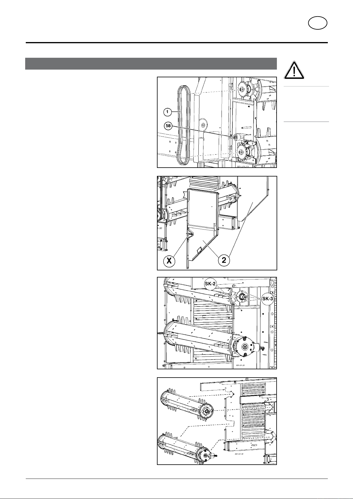
Removal of regulating rollers
REGULATING ROLLERS
GB
1. Open trailer tailgate.
2. Relax chain tension (58) and take off drive
chain (1).
3. Remove metal plates (2) left and right.
Take care! Do not after the torque pre-tensioning (X)
4. Dismantling Upper Regulating Roller
remove the following screws, left and right:
- three screws (SK-3) on the flange bearing
- two screws (SK-2) on the guard ring
5. Dismantling the Lower Regulating Roller
remove two screws (SK-2) on the guard ring, left and
right
6. Slide regulating rollers backwards.
7. Re-fit metal plates (2) left and right again.
Take care!
Do not reach into
regulating rollers
area while drive
motor is still
running.
8. Adjusting the switch
- see next page
0700_GB-DOSIERER_548
- 24 -
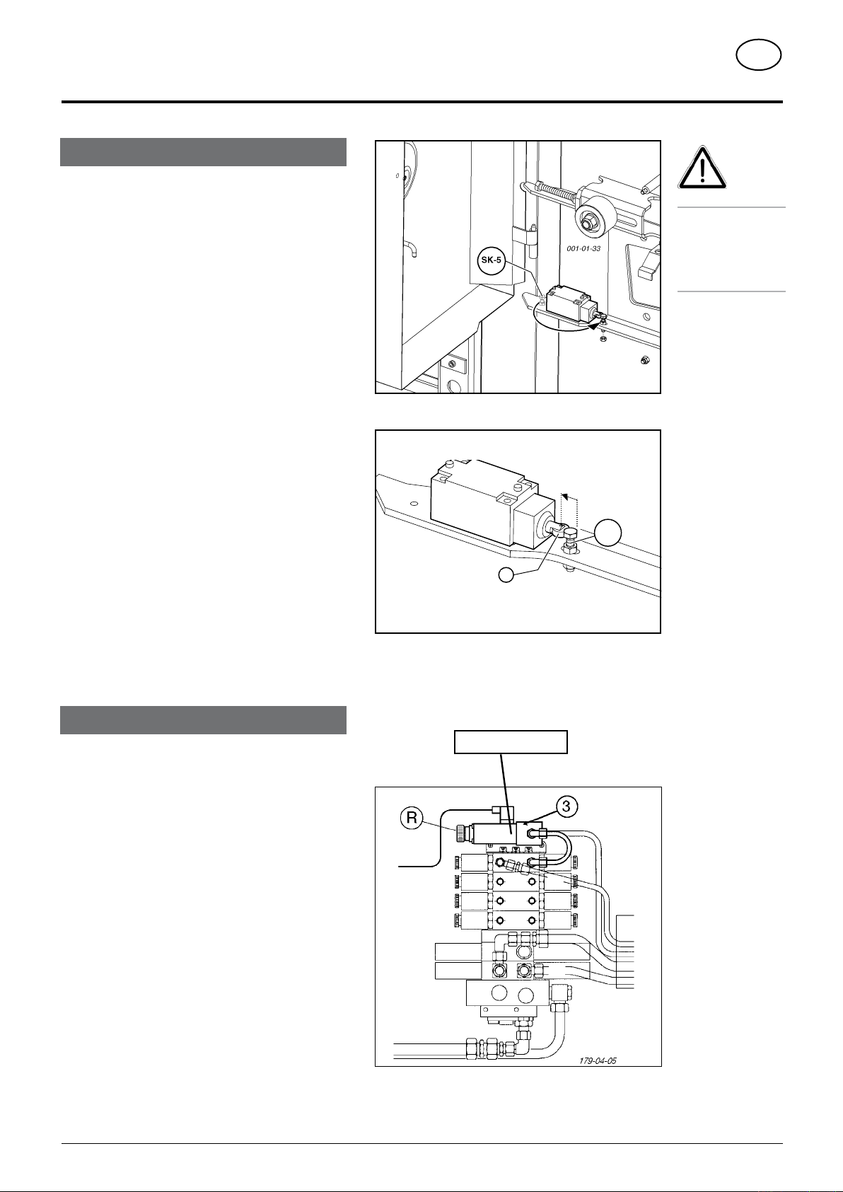
Scraper floor switch
001-01-34
A
SK-5
B
90
General
Where regulating rollers are built in, the screw (SK-5) is
situated behind the switch and has no function there.
The switch slider (90) is held in position A by means of a
component on the regulating roller.
The scraper floor drive can only be switched on as
follows:
- by means of the automatic loader
or
- by activating the scraper floor switch on the switch
console
Where regulating rollers have been dismantled, the switch
slider (90) would be in position B. In this position, the
scraper floor drive is constantly switched off. However this
is not required in the loading and unloading procedures.
Thus, where the regulating rollers have been dismantled,
the switch must be fixed in position A. This is achieved
by means of the bolt supplied (SK-5).
REGULATING ROLLERS
A greater injury
behind opened
protective covers.
GB
Note!
danger exists
when working
Setting when regulating rollers have been
dismantled
1. Push the switch slider (90) into position A
2. Screw the bolt (SK-5) down in the elongated hole, so
that the switch slider (90) remains fixed in position A.
Installing an oil pressure switch
It is recommended that an oil pressure switch (3) be installed
when operating without regulating rollers.
When the load presses against the tailgate, the scraper
floor drive is automatically switched off by means of the
oil pressure switch.
The oil pressure switch has no function when regulating
rollers are installed.
- Electro-connection see spare parts list, circuit diagram
see supplement.
- For setting see chapter “MAINTENANCE”
220 - 230 bar
0700_GB-DOSIERER_548
- 25 -
TD 57
/
91/5
6
TOP FRAME SECTION
GB
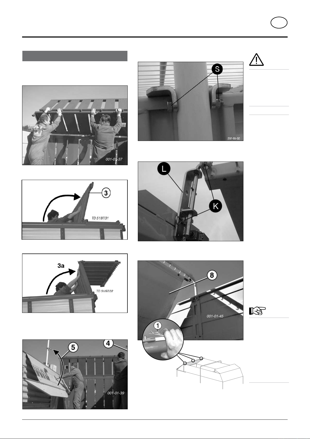
Assembling the top frame section
• It is imperative that the machine stand horizontally and
that two people carry out this modification.
• Danger of injury!
1. Swing upper railing (3) up
4. Screw side panel with holder (S)
Attention!
• It is imperative
that the machine
stand horizontally
and that two
people carry out
this modification.
• Danger of injury!
5. Mount the guide plate (L)
- fix with linch pin (K)
2. Swing lower railing (3a) up
3. Swing front side wall up
- left and right
6. Install tarpaulin (8) with linch pin (1).
Note!
When the dry
forage extension
is up, the rear
tarpaulin (8)
must be removed
when using
the regulating
rollers otherwise
damage could
occur to the
tarpaulin.
7. Connect top ropes
0600_GB-Aufbauoberteil_5543
- 26 -
DIRECT CONTROL - OPERATION
GB
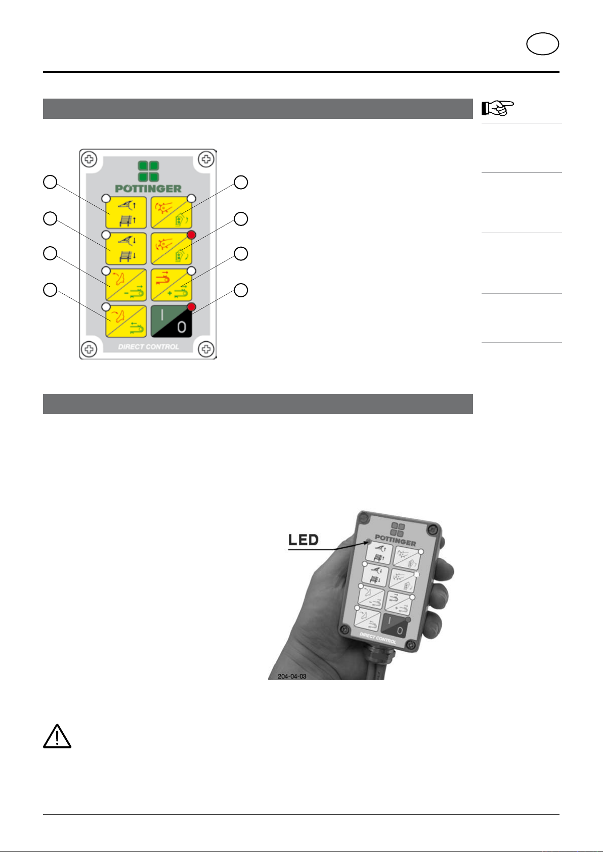
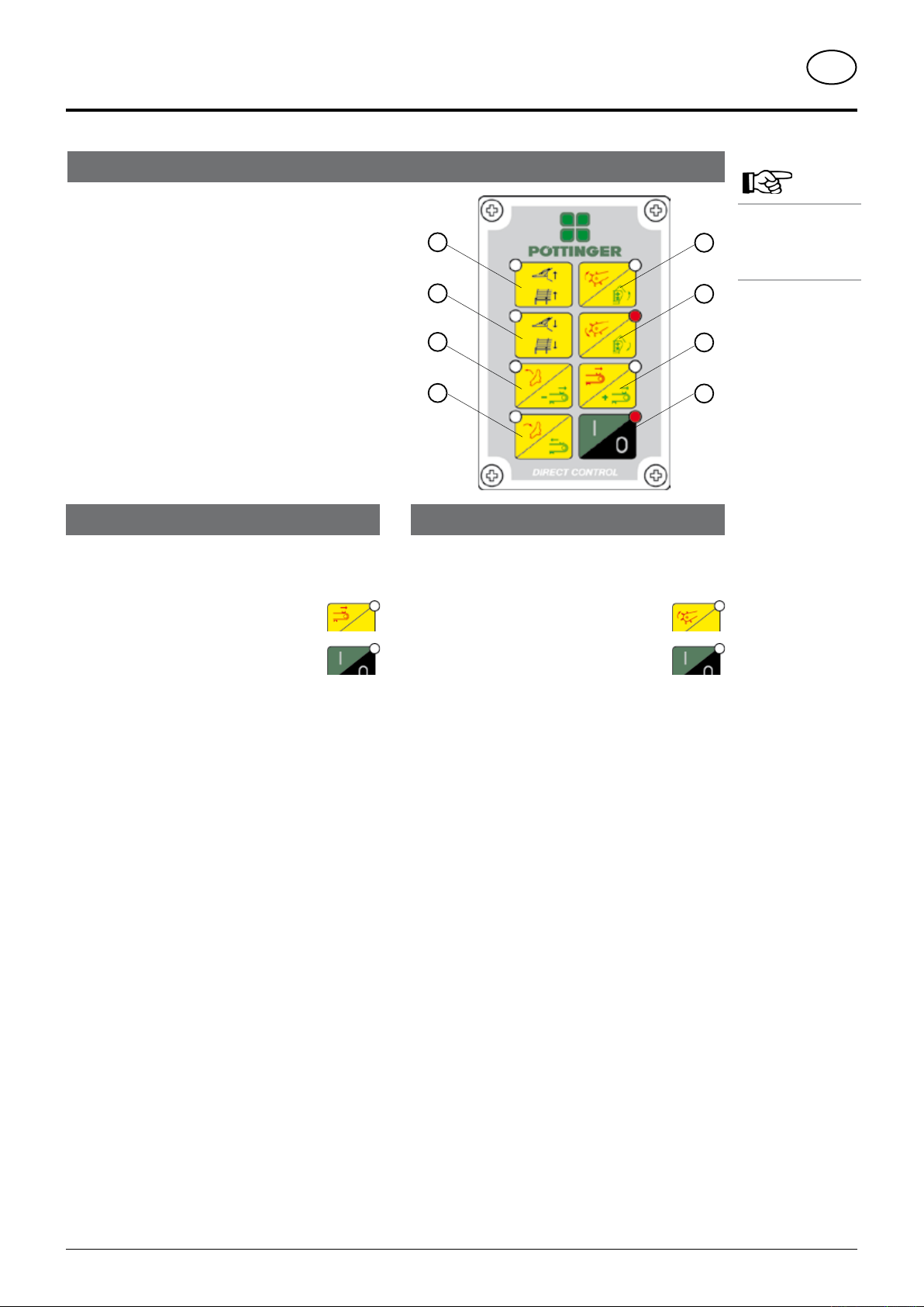
"DIRECT CONTROL" operating unit
Meaning of control panel buttons
1 Raising pivoting drawbar
Raise forage top frame
1
2
3
4
5
2 Lower pivoting drawbar
Lower forage top frame
3 Swing cutting unit in
6
Reduce scraper oor unloading speed
4 Swing cutting unit out
Scraper oor forward run
7
5 Raising pick-up
Open tailgate (with dosing roller on)
8
6 Lower pick-up
Close tailgate (with dosing roller off)
7 Scraper oor back run (= touch function)
Increase scraper oor unloading speed
8 ON/OFF button
- Change to other operation mode (red/green)
- STOP button
Operation is divided
and unloading
The red symbols
with the red LED
to the loading
The green symbols
with the green
LED are allocated
to the unloading
The black symbols
are available for
both operation
Note:
into loading
functions.
are allocated
functions.
functions.
modes
Carry out required hydraulic function
Switching on operating device
Press the I/O key for a few seconds
- the integrated control lamp glows red
Loading functions (= red symbols)
- Loading functions are always activated after switching
on
- The LED in the I/O key glows red
- Only the red symbol functions are active
- The required hydraulic function is carried by pressing
the appropriate key
- the (LED) in the selected key glows red
Unloading functions (= green symbols)
- The LED in the I/O key glows green
- Only the green symbol functions are active
- The required hydraulic function is carried by pressing
the appropriate key
- the (LED) in the selected key glows green
The pivoting drawbar (= black symbols) can
be actuated in both levels
Should the forage top frame be adjusted, the
operating device must be changed also
(see key description “Pivoting drawbar /
Forage top frame”)
Change to other operation mode
Briefly press button I/O
- the (LED) changes to green
Control light (LED)
If one of the control lights (LEDs) lights up, it means that
that particular function has been activated.
The example on the illustration above shows
- The top left integrated control light (LED) is on
- The function “raise pivoting drawbar” is carried
out.
0601-GB-DIRECT-CONTROL_563
- 27 -
DIRECT CONTROL - OPERATION
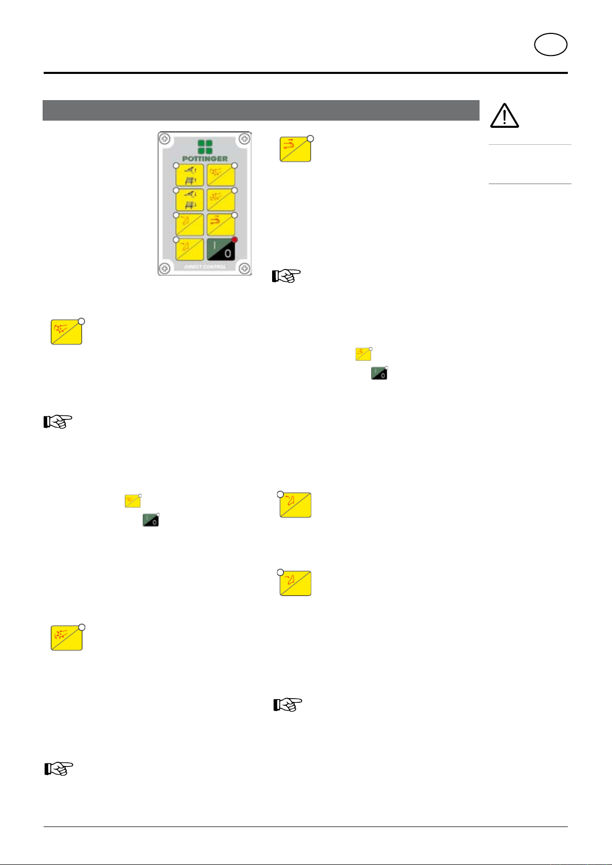
Loading functions
GB
- Loading f unct ions are
always activated after
switching on
- The LED in the I/O key
glows red
- Onl y t he red s y m bol
functions are active
- Se l e c t t he r e qu i red
hydraulic function
- The (LED) in the selected
key glows red
Press button and hold (= touch function)
- pick-up is raised
- the integrated LED lights up
Adjustment process:
- The operating device is switched off in the starting
Raising pick-up
Note!
Key is also used to select the automatic
unloader
position
Press button and hold (= touch function)
- thescraperoormovesatmaximumspeedtowards
- the integrated LED lights up
- the scraper oor remains still after releasing the
Adjustment process:
- The operating device is switched off in the starting
- Press and hold
Briefly press button
- The LED blinks and an acoustic sound signals the
Status is shown each time the operating device is
- LED blinks briefly = switched on
- LED does not blink = switched off
Scraper floor back run
the tailgate
key
Note!
Key is also used to select the automatic
1)
loader
position
key, then
(2 secs.)
status change.
switched on.
Safety hints!
See the relevant
chapters in this
operating manual!
- Press and hold
Briefly press button
- The LED blinks and an acoustic sound signals the
status change.
Status is shown each time the operating device is
switched on.
- LED blinks briefly = switched on
- LED does not blink = switched off
Press button (= rest function)
- pick-up is lowered
- Pick-upremainsintheoatingposition
- the integrated LED lights up
The function can only be cancelled out using the “Raise
Pick-up” key
Lower pick-up
Note!
If actuating another function, the Pick-up function
is locked for this time period
key, then
(2 secs.)
Press button and hold (= touch function)
- Cutting unit is swung in under pressure
Press button and hold (= touch function)
- cutting mechanism is swivelled out
With the cutting unit sensor available (as option) the
LED signals the swung out status
- Signal tone when Pick-up is lowered
Swing cutting unit in
Swing cutting unit out
Note!
For automatic loader and unloader see chapter
“Automatic Loading and Loading”.
0601-GB-DIRECT-CONTROL_563
- 28 -
1)
Only if loading gates are available
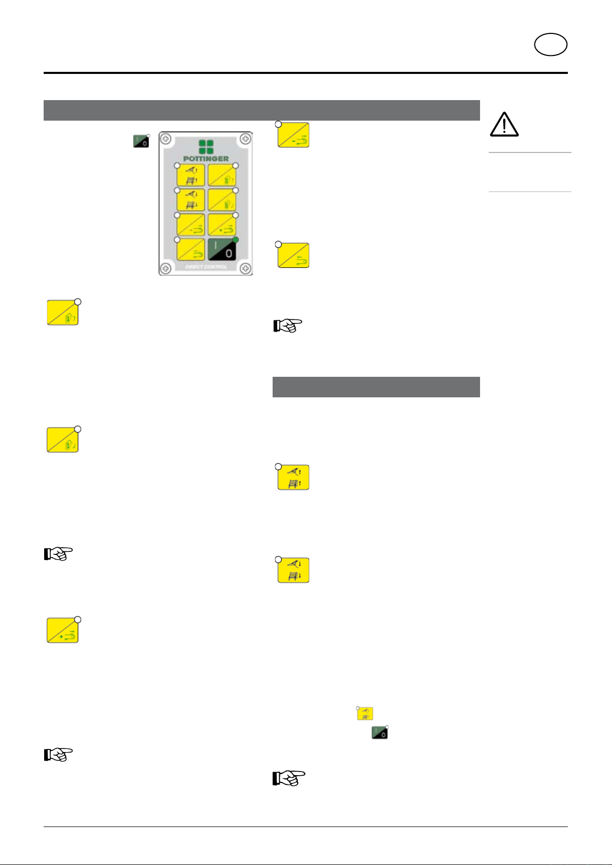
Unloading functions
- Briefly press button
- The mode is changed
- The LED in the I/O key
glows green
- Only the green symbol
functions are active
- Se l e c t t he r e qu i red
hydraulic function
- The (LED) in the selected
key glows green
Open tailgate
Press button (= rest function)
- the tailgate is raised
- the dosing rollers are switched on (if provided)
- the integrated LED lights up
DIRECT CONTROL - OPERATION
Decrease scraper floor speed
Briey press button (= touch function)
- decrease scraper floor back run speed
- the integrated LED lights up
- the speed is reduced further each time the key is
pressed
Scraper floor forward run
Press button and hold (= touch function)
- Scraper floor moves toward the Pick-up
- the integrated LED lights up
Note!
Use this key to stop scraper floor back run
also
Pivoting drawbar / Forage top frame
GB
Safety hints!
See the relevant
chapters in this
operating manual!
Close tailgate
Press button (= rest function)
- the tailgate is lowered
- the scraper floor is stopped
- the dosing rollers are switched off (if provided)
- the integrated LED lights up
Note!
If the tailgate automatic is interrupted by
another function (e.g. pivoting drawbar), the
tailgate remains on hold until the other function
is finished.
Unload scraper floor and
increase scraper floor speed
Press button (= rest function)
- the scraper floor runs backwards (when tailgate is
opened)
- the integrated LED lights up
The speed can be increased through further
pressing
Note!
After 5 seconds the up-to-date value is stored
and used as the start value for the next unloading
procedure (only with automatic unloading)
These functions can be carried out with the red as well
as the green LEDs
- The “pivoting drawbar” function is the standard
setting.
Raising pivoting drawbar /
Raise forage top frame
Press button and hold (= touch function)
- wagon is raised at the front or
- forage top frame is raised (switch over)
Lower pivoting drawbar /
Lower forage top frame
Press button and hold (= touch function)
- wagon is lowered at the front or
- forage top frame is lowered (switch over)
- If the “Forage top frame” function is required, switch
to another mode
Adjustment process:
- Switch operating device off
Press and hold
-
Briefly press button
- Both LEDs “Forage top frame raise” and “Forage
top frame” lower blink alternatively
Each time the operating device is switched
off the setting reverts to the pivoting drawbar
function.
key, then
(2 secs.)
0601-GB-DIRECT-CONTROL_563
- 29 -
Automatic Loader- unloader 3)
Check status:
1. Switch operating device off using button 8
(LED 8 does not light up)
2. Switch operating device on using
LED 7 lights up briefly:
Automatic loader is activated
LED 7 remains dull:
Automatic loader is deactivated
LED 5 lights up briefly:
Automatic unloader is activated
LED 5 remains dull:
Automatic unloader is deactivated
Status is shown each time the operating device is
switched on.
button 8
DIRECT CONTROL - OPERATION
1
2
3
4
5
6
7
8
loader needs to be
GB
Take note!
The automatic
switched on only
once.
Switching on automatic loader
Adjustment process:
The operating device is switched off in the starting
position
- Press
and then
- Briefly press
until LED 7 lights up briefly and an acoustic
signal sounds
Advantages of the automatic loader
- very compacted load
- minimum blockages in the feeder channel
- prevents overloading the entire drive
- forage protection
- relieves the driver
- increase in load capacity
Control of the automatic loader through
- level sensor below
- level sensor (flap above)
- oil pressure switch
button 7 and hold
button 8 (2 seconds)
3)
3)
3)
Switching on automatic unloader
Adjustment process:
The operating device is switched off in the starting
position
- Press
and then
- Briefly press
until LED 5 lights up briefly and an acoustic
signal sounds
Advantages of the automatic unloader
- fast, efficient and even unloading
- forage protection when unloading
- One press of the button opens the tailgate and starts
Functional procedure
- open the tailgate
- Scraper floor starts at the given speed
button 5 and hold
button 8 (2 seconds)
unloading
Functional procedure
- A level sensor reacts
- scraper floor switches on automatically
- forage conveyed to the rear
- procedure repeats until loading space is full
WAGON FULL indicator
• when the oil pressure switch registers excessive
pressure
- double horn tone sounds on control panel
0601-GB-DIRECT-CONTROL_563
- 30 -
3)
Only if level sensors are available
 Loading...