


GB
/PERATOR@SMANUAL
).3425#4)/.3&/202/$5#4$%,)6%290AGE
4RANSLATIONOFTHEORIGINAL/PERATING-ANUAL
NOVAALPIN 226 (Type PSM 317 : + . . 01001)
NOVAALPIN 266 (Type PSM 318 : + . . 01001)
99 317.GB.80I.0
.R
Disc mower
Ihre / Your / Votre • Masch.Nr. • Fgst.Ident.Nr.

GB
Dear Farmer
You have just made an excellent choice. Naturally we are very happy
and wish to congratulate you for having chosen Pöttinger. As your
agricultural partner, we offer you quality and efciency combined with
reliable servicing.
In order to assess the spare-parts demand for our agricultural machines
and to take these demands into consideration when developing new
machines, we would ask you to provide us with some details.
Furthermore, we will also be able to inform you of new developments.
Important information concerning Product
Liability.
According to the laws governing product liability, the manufacturer and dealer are obliged to hand the
operating manual to the customer at the time of sale, and to instruct them in the recommended operating,
safety, and maintenance regulations. Conrmation is necessary to prove that the machine and operating
manual have been handed over accordingly.
For this purpose,
document A is to be signed and sent to Pöttinger,
-
document B remains with the dealer supplying the machine,
-
- and the customer receives
In accordance with the laws of product liability, every farmer is an entrepreneur.
According to the laws of product liability, property damage is damage caused by a machine and not to
it. An excess of Euro 500 is provided for such a liabilioty.
In accordance with the laws of product liability, entrepreneurial property damages are excluded from
the liability.
Attention! Should the customer resell the machine at a later date, the operating manual must be given
to the new owner who must then be instructed in the recommended regulations referred to herein.
document C.
ALLG./BA SEITE 2 / 0000-GB

GB
INSTRUCTIONS FOR
PRODUCT DELIVERY
Dokument D
ALOIS PÖTTINGER Maschinenfabrik GmbH
A-4710 Grieskirchen
Tel. (07248) 600 -0
Telefax (07248) 600-511
GEBR. PÖTTINGER GMBH
D-86899 Landsberg/Lech, Spöttinger-Straße 24
Telefon (0 81 91) 92 99-111 / 112
Telefax (0 81 91) 92 99-188
According to the product liability please check the above mentioned items.
Please check. X
GEBR. PÖTTINGER GMBH
Servicezentrum
D-86899 Landsberg/Lech, Spöttinger-Straße 24
Telefon (0 81 91) 92 99-130 / 231
Telefax (0 81 91) 59 656
Machine checked according to delivery note. All attached parts removed. All safety equipment, drive shaft and operating
devices at hand.
Operation and maintenance of machine and/or implement according to operating instructions explained to the customer.
Tyres checked re. correct pressure.
Wheel nuts checked re. tightness.
Drive shaft cut to correct lenght.
Correct power-take-off speed indicated.
Fitting to tractor carried out: to three-point linkage
Trial run carried out and no defects found.
Functions explained during trial run.
Pivoting in transporting and operating position explained.
Information given re. optional extras.
Absolute need to read the operating manual indicated.
In order to prove that the machine and the operating manual have been properly delivered, a confirmation is necessary.
For this purpose please do the following:
- sign the
(in case of Landsberg equipment: to the company Landsberg)
document B stays with the specialist factory delivering the machine.
-
document C stays with the customer.
-
GB-0600 Dokum D Anbaugeräte
document A and send it to the company Pöttinger
- 3 -

WARNING SIGNS
CE sign ......................................................................5
Meaning of warning signs.......................................... 5
ATTACHING TO TRACTOR
Attaching in general ................................................... 6
Driveshaft ................................................................... 6
Road Transport .......................................................... 6
Special attachment .................................................... 7
Guard plates and protective aprons .......................... 8
Transport position (< 3 m) .........................................
Working position ........................................................ 8
Quick-coupler (1) ....................................................... 9
Spring tension............................................................ 9
Attaching problems ...................................................9
STARTING WORK
Important points before starting work ..................... 11
Watch for the direction of rotation of the mowing
discs ........................................................................11
Mowing .................................................................... 11
Driving motor speed ................................................ 12
Safety hints .............................................................. 13
COLLISION SAFETY DEVICE
Collision safety device ............................................. 14
Mechanical collision safety device, ........................ 14
Function of collision safety device .......................... 14
MAINTENANCE
Safety point ............................................................. 15
General maintenance hints ...................................... 15
Cleaning of machine parts ....................................... 15
Parking in the ope .................................................... 15
Winter storage ......................................................... 15
Drive shafts .............................................................. 15
Hydraulic unit ........................................................... 15
Cutter bar oil level check ....................................... 16
Cutter bar-oil change ............................................... 16
Angular gear ............................................................17
Installing cutter blades ............................................ 17
V-belt tension ........................................................... 17
Lubrication ............................................................... 18
Checking wear on mowing blade holders ............... 19
Holder for a quick change of cutter blades ............. 20
Checking the mowing blade suspension................. 20
Changing the Cutter Blades (up to 2003 model) ..... 20
Changing the Cutter Blades (from 2004 model) ...... 21
Storing the lever ...................................................... 21
TECHNICAL DATA
Technical data .......................................................... 22
Position of Vehicle Identification Plate ....................22
The defined use of the mower unit .......................... 22
SUPPLEMENT
Recommendations for work safety ......................... 25
Driveshaft ................................................................. 26
Special attachment .................................................. 28
Maximum drive shaft angle ..................................... 28
Lubricants ................................................................ 30
Repairs on the cutter bar ......................................... 32
Combination of tractor and mounted implement .... 33
TABLE OF CONTENTS
Observe Safety
8
GB
Attention!
Hints in the
supplement!
0800_GB-Inhalt_317
- 4 -
The CE sign, which is affixed by the manufacturer, indicates outwardly that this machine
495.167
conforms to the engineering guideline regulations and the other relevant EU guidelines.
EU Declaration of Conformity (see supplement)
By signing the EU Declaration of Conformity, the manufacturer declares that the machine being
brought into service complies with all relevant safety and health requirements.
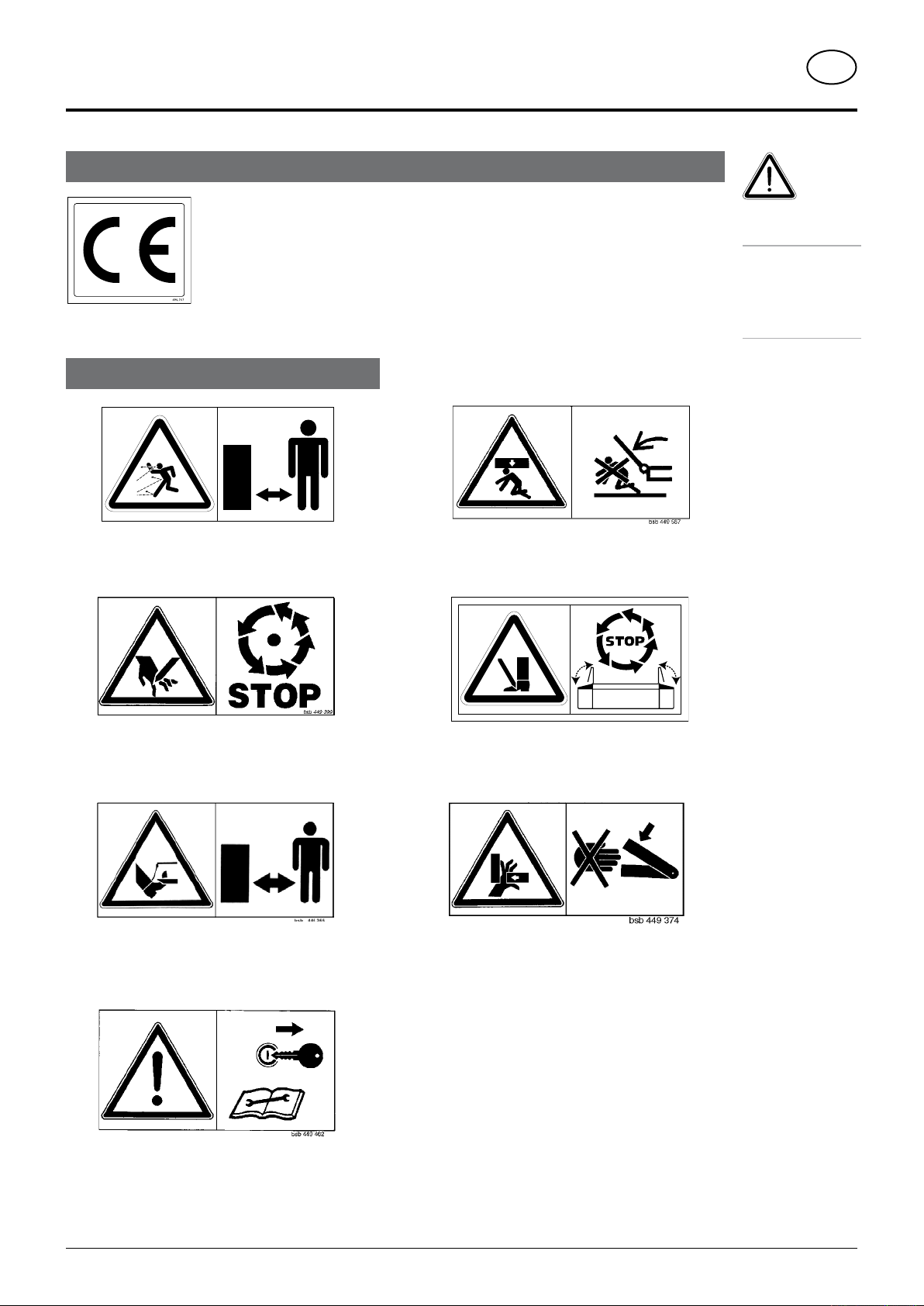
Meaning of warning signs
CE sign
WArning signs
Recommendations
for work safety
All points referring
to satety in this
indicated by this
GB
manual are
sign.
Danger - flying objects; keep safe distance from the
machine as long as the engine is running.
Wait until all machine components have stopped
completely before touching them.
Stay clear of mower knife area as long as tractor engine
is running with PTO connected.
Stay clear of swinging area of implements
Close both side protective coverings before engaging
p.t.o..
Never reach into the crushing danger area as long as
parts may move.
Shut off engine and remove key before performing
maintenance or repair work.
9700_GB-Warnbilder_361
- 5 -
ATTACHing TO TrACTOr
GB
Attaching in general
1. Observe safety hints in supplement-A.
• Please also observe the hints in the chapter “Special
attachment”
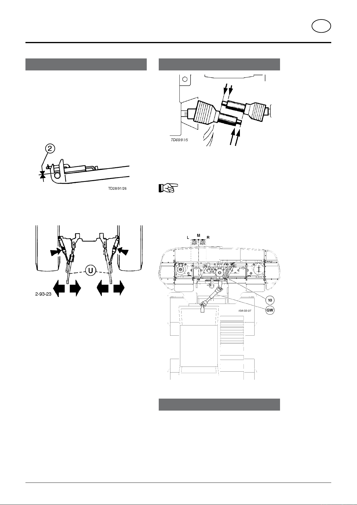
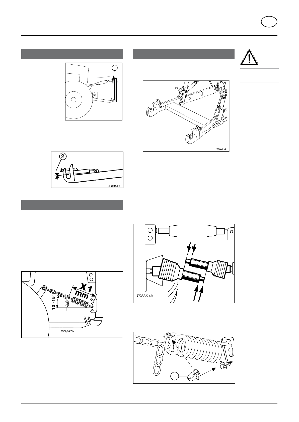
2. Mark off the implement at the tractor's threepoint linkage.
• Secure locking bolts with linch pins.
• Lock lower link bolts (2) so that they are free from
play.
3. Fasten lower hydraulic link (U) so that
implement cannot swing out sideways.
Driveshaft
- Before initial operation, check drive shaft length and
adapt if necessary (see chapter “Adapting to Drive
Shaft” in Supplement B also).
Optional extra: Hydraulic cylinder
Important!
The cutter bar can be moved left (L) or right
(R) using hydraulic cylinder (10).
Take this offsetting action into account
when shortening the drive shaft.
M = central position
4. Connect hydraulic lines (Hyd) on the plug-in
connector with the double-action control
valve.
Road Transport
• Observe the regulations issued by your country's
legislative body.
• Travelling on public roads may only be undertaken as
is described in the chapter "Transporting Position".
• Fasten lower hydraulic link (U) so that implement cannot
swing out sideways.
0500-GB ANBAU_317
- 6 -
Special attachment
GW�
max.
TD 37/96/4
Because of the different lifting gears on various tractors
special attaching kits are to be used.
• see supplement-D
• see Spare Parts List also.
Maximum drive shaft angle
Most drive shafts in continuous operation may only be
angled to a maximum 25° (GW max.).
• Observe the advice in the drive shaft
manufacturer's operating manual.
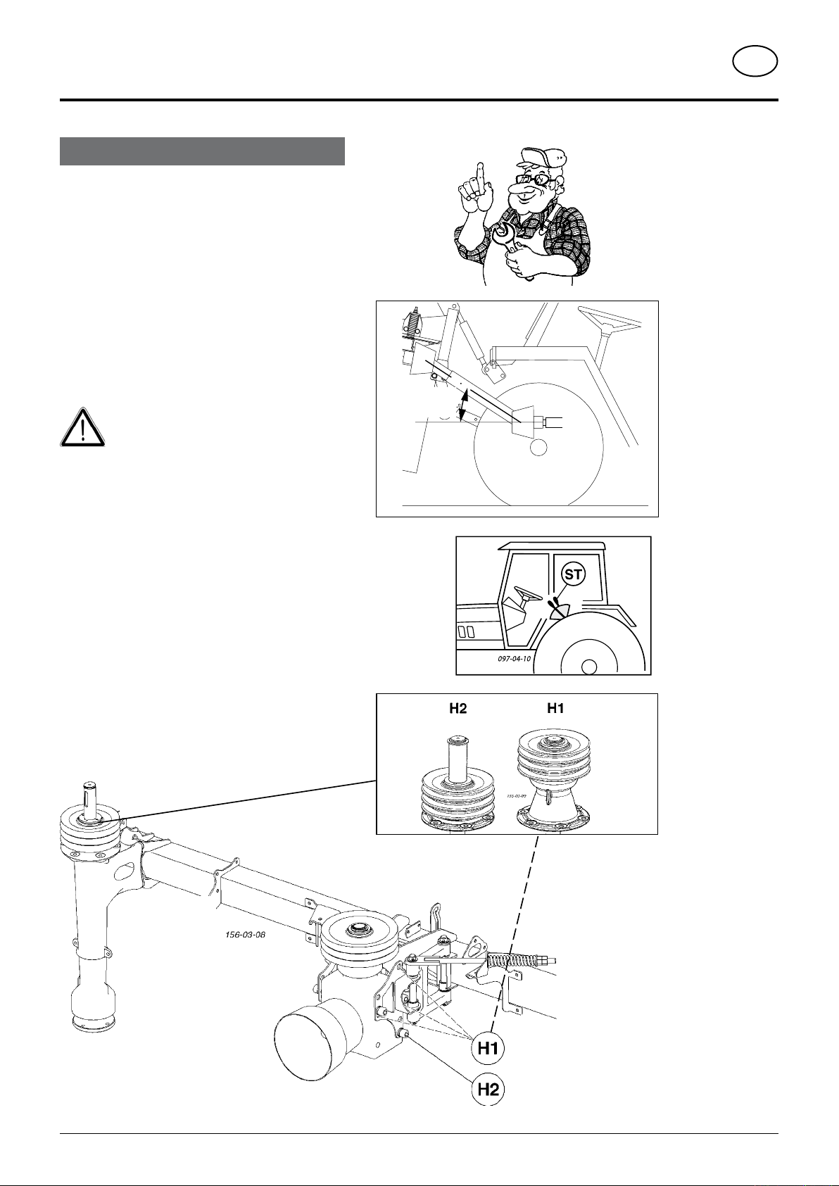
Gearing positions
Gearing can be fitted in two positions (H1, H2)
For this the relevant adaptors must also be fitted.
- see Spare Parts List
ATTACHing TO TrACTOr
GB
In order to prevent damage
- Limit the lifting gear’s lifting height
Limit the lifting height with lever (ST)
0500-GB ANBAU_317
- 7 -
ATTACHing TO TrACTOr
495.167
GB
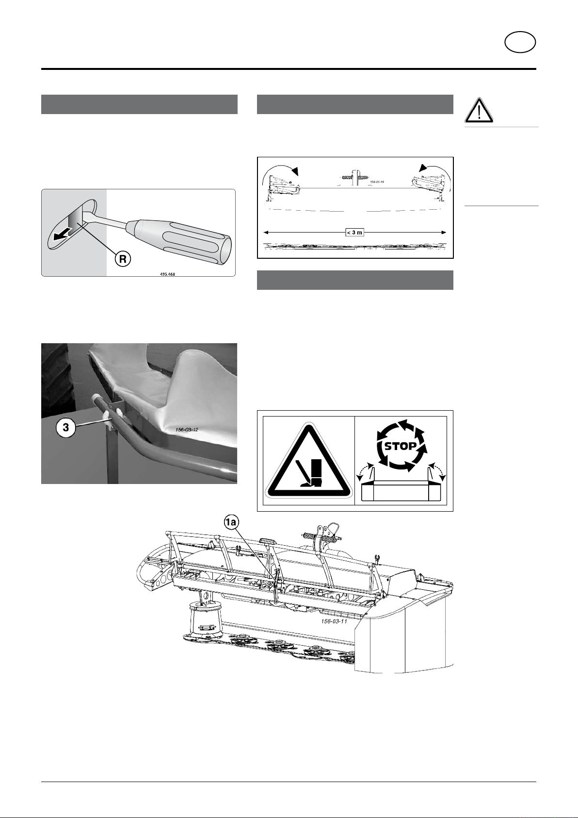
Guard plates and protective aprons
Guard plates and protective aprons can be raised when
maintenance work is to be done.
Open the locking bar „R“ with a suitable aid (e.g. screw
driver) and simultaneously swing the protector up.
Opening the side protector
- Unlock the catch (R) and swing protector up
- engage protective frame in holder (3)
- left and right
Transport position (< 3 m)
When both protective elements have been raised and
are engaged in the holder (3), the total width of the unit
is less than 3m.
Working position
Before commencing work
Turn the p.t.o. on only when all safety devices
(coverings, protective aprons, casings,
etc.) are in proper condition and attached
to the implement in the correct protective
positions.
For safety reasons mowing may only be
conducted in this position.
Attention!
For safety reasons
it is necessary to
wait for mowing
disks to stop
completely before
raising and securing guard plates.
Open front protector
- Unlock the catch (R) and
swing protector up
- lock holder in place
(1a)
Close front protector
- Disengage holder and
swing protector down
The catch will engage
automatically
Closing the side protectors
Swing the protector down, the locking bar engages
automatically and locks the protector against
unintentional opening.
0500-GB ANBAU_317
- 8 -
ATTACHing TO TrACTOr
TD28/91/28
1
TD29/93/2�
20�
GB
Quick-coupler (1)
- M o u n t s n a p
connector (Weiste
triangle) onto the
front lifting gear in
a vertical position
or inclined slightly
forward.
- Lock lower link bolts (2) so that they are free from
play.
Spring tension
Mounting kit (Optional extras)
The mower drum’s ground pressure is controlled through
spring tension
• The mowing bar should weigh 150kg resting on the
ground (75kg left and right).
- Raise the unit hydraulically
- Secure both chains
- Lower implement to ground.
Check angle 10° - 15°
Attaching problems
• For lifting gear with a crossbar between the lower links
damage to the cardan shaft could occur when lowering
the attached implement.
To prevent damage fit an uplift device between lifting
gear and Weiste triangle
In a case such as this please contact our Customer
Service Dept.
• For tractors where the cardan shaft end is located quite
far forward, the length must be extremely shortened.
When the implement is engaged then there is insufficient
casing to over the drive shaft.
In this case the mounting frames (K1, K2) are to be
fitted in the relevant positions (see Supplement-D)
Safety
hints:
see supplement-A1
Pkt. 8a. - h.)
Setting measurement "X1"
- Slip the hose clamp (20) onto the tension spring.
Doing this means that spring tension does not have to
be checked every time unit is attached to tractor.
Only when changing tractors is the setting (X1) to be
checked and if necessary reset.
0500-GB ANBAU_317
- 9 -
- 10 -
0500-GB ANBAU_317
ATTACHing TO TrACTOr
GB
Snap connector (Weiste triangle)
Pay particul arattention before initial attachment
to Tractor!
Attention!
For front lifting gear with double-action
hydraulic cycle (danger of damage)!
Remedy:
- Switch control valve to single-action
- Convert front lifting gear to single-action function
(bypass line) through a specialist work shop.
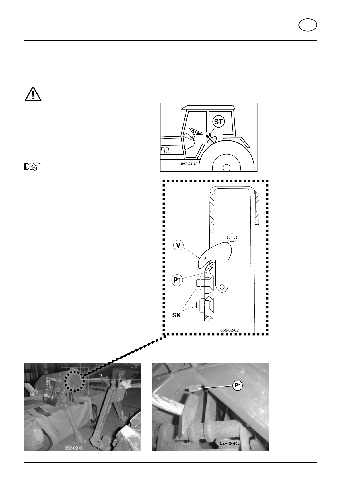
• When the mower is attached to the tractor,
the the hydraulic control (ST) must not be
set at „Lower“.
• Immediately after such an operating error,
reset the adjustable plate (P1).. Replace
damaged parts beforehand.
The following could happen after an operating error:
- the position of the plate (P1) has changed in the slot;
the gap to the locking hook (V) is therefore too great,
- the locking hook (V) breaks,
Reset the adjustable plate (P1)
1. Loosen screws (SK) slightly
- do not loosen too much; the plate (P1) should be
able to move in the slot when tapped lightly with a
hammer.
2. Couple the mower to the tractor´s lifting gear
3. Position the adjustable plate (P1) so that the locking
hook (V) can still be unlatched. The gap to the hook
should be as narrow as possible.
4. Uncouple the mower from the tractor´s lifting gear.
5. Tighten screws (SK) to 65 Nm.
TD40/94/16
156-03-05
NOVAALPIN 226
NOVAALPIN 266
sTArTing WOrk
GB
Important points before starting work
After the first hours of operation
• Retighten all knife screw fittings.
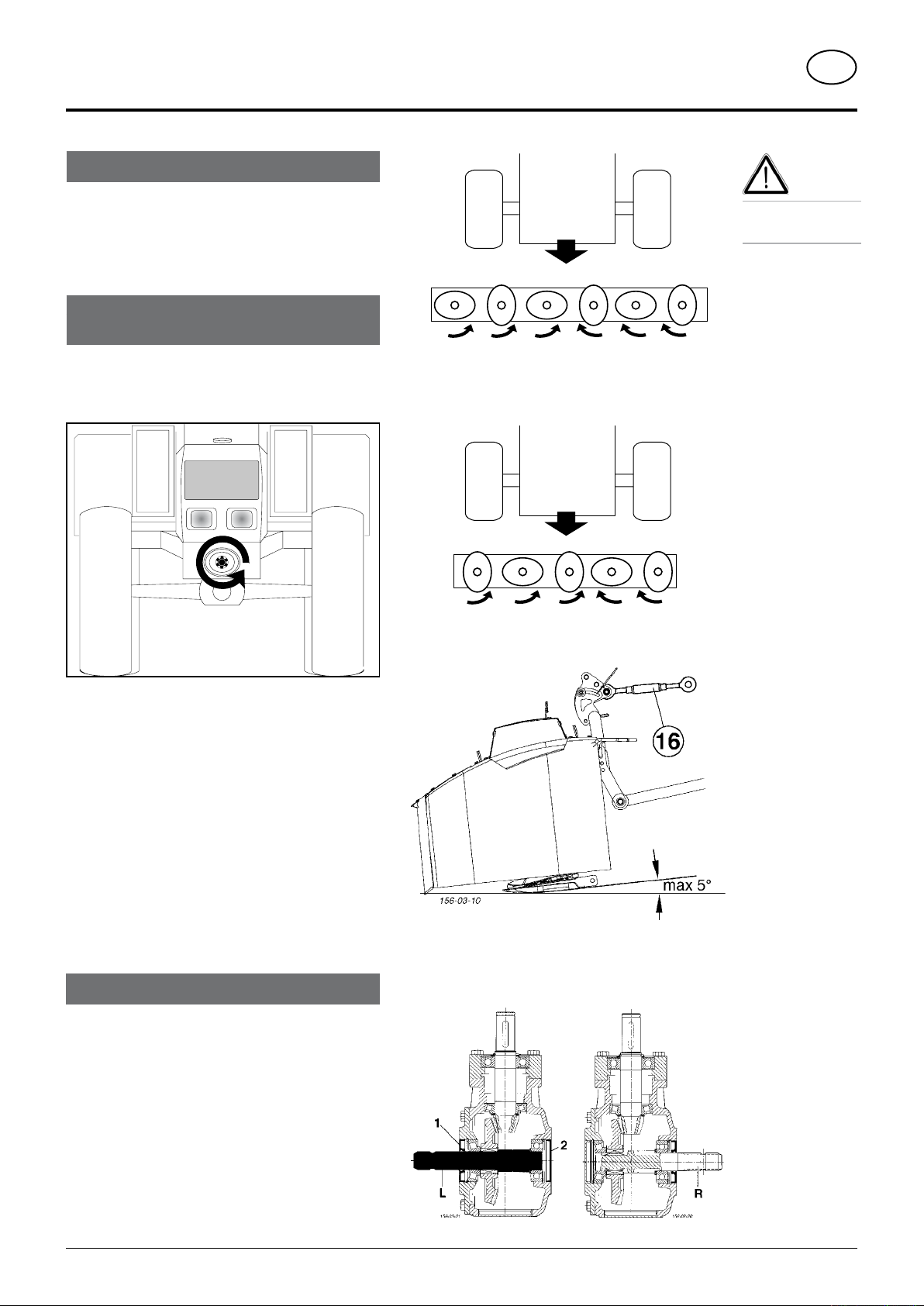
Watch for the direction of rotation of the
mowing discs
General
For mowing, the power take-off shaft drive should be
switched to turn to the left.
Safety
hints:
see supplement-A
Pkt. 1. - 7.)
Remedy, if the tractor’s power take-off shaft drive
cannot be switched to turn to the left:
Mount the drive shaft in the gearing in position L
Note: With this change replace the rotary shaft seal (1)
and the sealing cover (2) with new ones (see Spare
Parts List)
Mowing
1. Adjust cutting height by turning upper link
spindle (16) (cutter disc inclination: max. 5°)
2. Before mowing, throw-in p.t.o. slowly outside
crop and bring mower drums up to full
speed.
Noises conditional to p.t.o. free-wheel system can
be prevented through an even continious increase in
r.p.m.
- Travelling speed is set according to ground conditions
and crop.
0300-GB EINSATZ_317
- 11 -

Driving motor speed
The machine can be adapted to the r.p.m. (540 rpm, 1000
rpm) being used.
Fit both V-belt pulleys (Ø212 mm and Ø160 mm) in the
relevant position (see diagram).
sTArTing WOrk
GB
0300-GB EINSATZ_317
- 12 -
 Loading...