

Pottinger LADEPROFI 4 Profimatic, LADEPROFI IV, Profi Gp 1, PROFI GP 2 Operating Instructions Manual

Operating instructions
+ INSTRUCTIONS FOR PRODUCT DELIVERY . . . Page 3
Ihre / Your / Votre • Masch.Nr. • Fgst.Ident.Nr.
GB
LADEPROFI IV
(Type 105 u. 106)
LADEPROFI 4 Profimatic
(Type 105 u. 106)
Nr. 99 106.GB.80A.0

ALLG./BA SEITE 2 / 9300-GB
Important information concerning Product Liability.
According to the laws governing product liability, the manufacturer and dealer are
obliged to hand the operating manual to the customer at the time of sale, and to
instruct them in the recommended operating, safety, and maintenance regulations.
Confirmation is necessary to prove that the machine and operating
manual have been handed over accordingly.
For this purpose, document A is to be signed and sent to Pöttinger,
document B remains with the dealer supplying the machine, and the
customer receives document C.
In accordance with the laws of product liability, every farmer is an entrepreneur.
According to the laws of product liability, property damage is damage caused by a
machine and not to it. An excess of Euro 500 is provided for such a liabilioty.
In accordance with the laws of product liability, entrepreneurial property damages
are excluded from the liability.
Attention! Should the customer resell the machine at a later date, the operating
manual must be given to the new owner who must then be instructed in the
recommended regulations referred to herein.
GB
Dear Farmer
You have just made an excellent choice. Naturally we
are very happy and wish to congratulate you for
having chosen Pöttinger. As your agricultural partner,
we offer you quality and efficiency combined with
reliable servicing.
In order to assess the spare-parts demand for our
agricultural machines and to take these demands
into consideration when developing new machines,
we would ask you to provide us with some details.
Furthermore, we will also be able to inform you of new
developments.

Dokument D
GB-0100 Dokum D Anhänger
- 3
ALOIS PÖTTINGER Maschinenfabrik GmbH
A-4710 Grieskirchen
Tel. (07248) 600 -0
Telefax (07248) 600-511
GEBR. PÖTTINGER GMBH
D-86899 Landsberg/Lech, Spöttinger-Straße 24
Telefon (0 81 91) 92 99-111 / 112
Telefax (0 81 91) 92 99-188
GEBR. PÖTTINGER GMBH
Servicezentrum
D-86899 Landsberg/Lech, Spöttinger-Straße 24
Telefon (0 81 91) 92 99-130 / 231
Telefax (0 81 91) 59 656
❑ Machine checked according to delivery note. All
attached parts removed. All safety equipment, drive
shaft and operating devices at hand.
❑ Operation and maintenance of machine and/or
implement according to operating instructions
explained to the customer.
❑ Tyres checked re. correct pressure.
❑ Wheel nuts checked re. tightness.
❑ Drive shaft cut to correct lenght.
❑ Correct power-take-off speed indicated.
❑ Mechanical functions (opening of rear gate, pivoting
of cutting mechanism out/in, etc.) demonstrated and
explained.
❑ Removing and mounting of knives explained.
❑ Electrical connection to tractor established and
checked re. correct supply (54 g connected). Note
references in operating manual.
Please check. X
According to the product liability please check the above mentioned items.
INSTRUCTIONS FOR
PRODUCT DELIVERY
GB
❑ Fitting to tractor carried out: hight of drawbar adjusted,
brake cable installed, hand brake lever assembled in
tractor cabin.
❑ Function of electrical installation checked and
explained.
❑ Hydraulic connection to tractor established and checked
re. correct supply.
❑ Hydraulic functions (drawbar, opening of rear gate, etc.)
demonstrated and explained.
❑ Handbrake and operating brake tested re. function.
❑ Trial run carried out and no defects found.
❑ Functions explained during trial run.
❑ Automatic on/off switch of loading mechanism checked.
❑ Pivoting in transporting and operating position
explained.
❑ Information given re. optional extras.
❑ Absolute need to read the operating manual indicated.
In order to prove that the machine and the operating manual have been properly delivered, a confirmation is necessary.
For this purpose please do the following:
- sign the document A and send it to the company P ttinger
(in case of Landsberg equipment: to the company Landsberg)
- document B stays with the specialist factory delivering the machine.
- document C stays with the customer.

- 4 -
106.GB.80A.0 INHALT
TABLE OF CONTENTS
GB
TABLE OF CONTENTS
warning signs ........................................................................5
Recommendations for work safety ........................................ 5
General safety tips for using the trailer..................................6
Travelling on roads ................................................................6
PUTTING INTO OPERATION ............................................... 6
Before starting work ..............................................................6
Checking before operation ....................................................6
Operating the swivelling supporting wheel ............................ 7
Hitching up the implement.....................................................7
Parking the implement .......................................................... 7
Adjusting drawbar to tractor’s towing coupler ........................8
Pivoting drawbar safety device check ................................... 8
Brake adjustment ..................................................................9
Adaption to tractor ................................................................. 9
BRAKE UNIT.........................................................................9
Initial operation ...................................................................... 9
Shortening the bowden cable ...............................................9
Safety Cable (max. 25 km und max. 4 to zul. Ges Gew.) ... 12
Abreißseil (nur bei Auflaufbremsanlage) ............................ 12
Drive shaft adaption ............................................................12
Hydraulic connection ........................................................... 12
Putting into operation ..........................................................12
Uncoupling and parking the trailer ...................................... 12
Parking in the open .............................................................12
Garaging for winter..............................................................12
Hydraulic connection ........................................................... 13
Standard position: with an open hydraulic system .............. 13
Take care! with tractors with a closed hydraulic system ..... 13
Operation elements ............................................................. 14
Mounting bracket.................................................................14
Operating elements ............................................................. 14
Pick-up and hydraulic drawbar ............................................14
Dry forage extension ...........................................................14
Tail gate ...............................................................................14
Operation of hydraulic scraper floor drive ........................... 14
Dry forage extension ...........................................................15
Swivelling cutter unit ........................................................... 15
Obstructions when swivelling ..............................................15
Alteration of gas container pressure ................................... 15
Maintenance........................................................................15
Operation errors ..................................................................16
Hydraulic connection ........................................................... 17
Power supply.......................................................................17
Standard position: with an open hydraulic system .............. 17
Installation and check of the electrohydraulic operation...... 18
Pivoting drawbar.................................................................. 18
Tailgate ................................................................................18
Scraper floor reverse run (KR) ............................................18
Pick-up ................................................................................18
Dry forage extension ...........................................................19
Swivelling cutter unit ........................................................... 19
Obstructions when swivelling ..............................................19
Alteration of gas container pressure ................................... 19
Maintenance........................................................................19
Trouble shooting ..................................................................20
Maintenance........................................................................20
Emergency handling of hydraulic valves in case of power
break down..........................................................................20
Hydraulic connection ........................................................... 21
Standard position: with tractors with an open hydraulic
system ................................................................................. 21
Power supply.......................................................................21
Installation and check of comfort operation.........................22
Check switch-off functions .................................................. 22
Dry forage extension ...........................................................24
Swivelling cutter unit ........................................................... 24
Obstructions when swivelling ..............................................24
Alteration of gas container pressure ................................... 24
Maintenance........................................................................24
Trouble shooting ..................................................................25
Emergency handling of hydraulic valves in case of power
break down ( - Baujahr 1997)..............................................25
Emergency handling of hydraulic valves in case of power
break down ( + Baujahr 1998).............................................26
Trouble shooting ..................................................................26
Adjusting the pick-up ........................................................... 27
Impact deflector adjustment (52).........................................27
Loading process in general .................................................27
LOADING THE TRAILER ....................................................27
Starting the loading process ...............................................27
To observe during the loading process! ..............................27
Finishing the loading process .............................................27
Trailer fill indicator (1 ........................................................... 27
Swivelling cutter unit in and out...........................................28
Folding cutter bar down.......................................................28
Folding two cutter bars down ..............................................29
Quick-insert cutters (M) ....................................................... 29
Handling quick-insert cutters ............................................... 29
Swivelling out a quick-insert cutter ...................................... 29
Installing a quick-insert cutter .............................................30
Cutter bar ............................................................................30
Removal and installation of a cutter ....................................30
Cutter installation ................................................................ 30
Maintenance........................................................................31
Direct grinding of cutter on cutter bar .................................. 31
Grinding of removed cutters ................................................ 31
Hydraulic opening and closing of the tail gate.....................33
Unloading with raised top frame..........................................33
WHEELS AND TYRES ....................................................... 34
Troubleshooting ...................................................................35
Advice for general maintence..............................................36
Spare parts .........................................................................36
Opening the side protectors ................................................36
Closing the side protectors..................................................36
Take care when entering the loading area .......................... 36
Tyre pressure ...................................................................... 37
Scraper floor chains ............................................................38
Starting transmission ..........................................................38
Hydraulic unit ...................................................................... 38
Cleaning of machine parts .................................................. 38
Brake adjustment ................................................................38
Optional equipment .............................................................39
Technical data ..................................................................... 39
Correct loading: ................................................................... 39
Lubrication chart .................................................................40
Lubrication chart .................................................................41
Lubrication chart .................................................................42
Recommendations for work safety ...................................... 47
DRIVESHAFT ..................................................................... 48
Auflauf-Achse mit Rückfahrautomatik ................................. 49
Einstellen der Nockenbremse Typ: 30-4010 (300x60) ......... 49
Auflaufbremsanlage ............................................................50
Abstellen des Anhängers ....................................................50
Fehlerursachen und deren Beseitigung ..............................51
Important! Additional Information ........................................52
Combination of tractor and mounted implement .................52

CE sign
The CE sign, which is affixed by the manufacturer, indicates outwardly
that this machine conforms to the engineering guideline regulations and
the other relevant EU guidelines.
EU Declaration of Conformity
By signing the EU Declaration of Conformity, the manufacturer declares
that the machine being brought into service complies with all relevant
safety and health requirements.
495.151
Meaning of warning
signs
Turn engine off when
adjustment, service and
repair work is to be done.
Never reach into the pick-up
area as long as tractor
engine is running with PTO
connected.
Never reach into the crushing
danger area as long as parts
may move.
Don't step on loading
platform if PTO is connected
to tractor and Engine is
running.
Stay clear of gate swinging
area while tractor engine is
running. Access only allowed
when safety lock is applied.
Recommendations for work safety
All points referring to satety in this
manual are indicated by this sign.
Wait until all machine
components have stopped
completely before touching
them.
Stay clear of gate swinging
area while tractor engine is
running.
- 5 -
AZB 9700-GB (511)
GB
WARNING SIGNS
Before starting work
a. Before commencing work, the operator must be aware of
all operating devices and functions. The learning of these
is too late after having already commenced operation!
b. The vehicle is to be tested for traffic and operating safety
before each operation.
c. The danger of being crushed or cut exists in the Pick-up,
cutting unit, tailgate and upper extension areas. All persons
must be shown out of these areas before activating hydraulic
equipment and turning on the drive.
d. Before driving the vehicle, the driver must ensure that
nobody will be endangered and that no obstructions are
present. If the driver is unable to see and have an overall
view of the roadway directly behind the trailer, he must be
guided by somebody while reversing.
e. Observe the safety tips which are attached to the trailer. An
explanation of what the individual graphic warning symbols
mean can be found on page 4.
f. Observe also the tips in the respective chapters and in the
supplement to this operating manual.
Checking before operation
The following tips should make the trailer's operation
easier for you. Detailled information for individual
points can be found in the respective chapters in this
operating manual.
1. Check that all safety equipment (coverings, casings, etc.)
are in proper order and fitted in position on the trailer.
2. Grease the trailer in accordance with the lubrication chart.
Check the gearing for tightness and the oil level.
3. Check that tyres have the correct air pressure.
4. Check that wheel nuts are sitting firmly.
5. Ensure the correct p.t.o.-r.p.m..
6. Make the electrical connections to the tractor and check
that they are correct. Take note of the tips in the operating
manual!
7. Carry out the following adaptions:
• Drawbar height
• Laying of brake cable
• Install hand brake lever in the tractor cabin.
8. Secure trailer using only the fixtures provided.
9. Cut drive shaft to the correct length and check the function
of the overload safety (see supplement).
10. Check the electronic unit function.
11. Connect hydraulic lines to tractor.
• Check hydraulic hoses for damage and wear.
• Ensure the correct connection.
12. All swivelling parts (tailgate, adjusting lever, etc.) must be
secured against dangerous position changes.
13. Check parking brake and service brake functions.
General safety tips for using the
trailer
Tips for travelling with the trailer
The handling of the tractor is influenced by the trailer
coupled to it.
• Danger of tipping exists when working on slopes.
• The driving must be adapted
to the corresponding terrain
and ground conditions.
• The towing vehicle is to be
sufficiently equiped with
weights at the front or at the
rear in order to guarantee the
steering and braking capacity
(a minimum of 20% of the
vehicle's tare weight on the
front axle).
• The transport of persons on the machine is not permitted.
Tips for coupling and uncoupling the trailer
• Danger of injury exists when coupling the implement to the
tractor!
• As long as the tractor is moving backwards, do not step
between it and the trailer when coupling.
• Nobody is to stand between the tractor and trailer without
the vehicles being secured against
rolling with the parking brake and/or
wheel chocks.
• Drive shaft connection or
disconnection is only to be undertaken
when the motor has stopped.
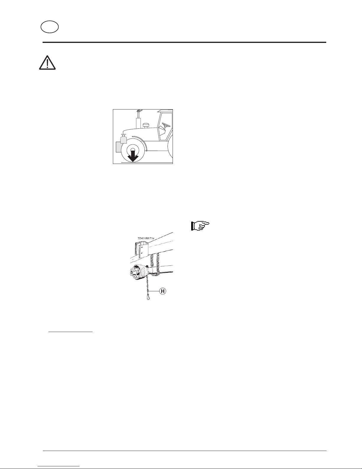
Parking the implement
• When the implement ist parked, either
remove the driveshaft and store it, or
secure it with a chain.
Do not use retaining chain (H) for this.
Only use the trailer according to regulations!
Regulations for Use: See chapter "Technical Data".
• The trailer's load limits (permitted axle load, support load,
total weight) may not be exceeded. The relevant details
are located on the right side of the trailer.
• In addition, observe the power limits of the tractor being
used.
Travelling on roads
• Observe the road rules.
• The tailgate must be closed when travelling on public
roads. Lighting devices must be fitted vertically to the road.
20%
Kg
GB
- 6 -
9500 GB INBETRIEBNAHME (511)
PUTTING INTO OPERATION
- 7 -
511 / STÜTZRAD 9800-GB
GB
SUPPORTING WHEEL
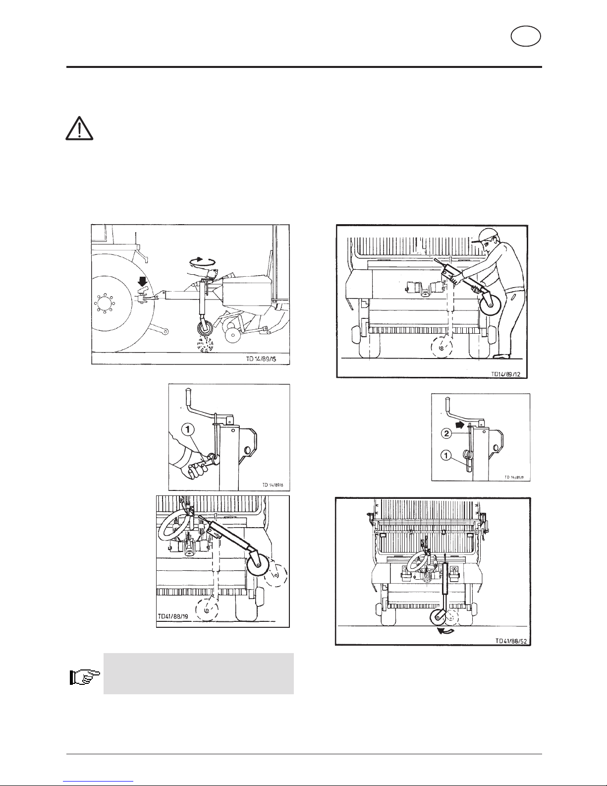
Operating the swivelling supporting wheel
Only use eccentric lever (1) when implement is hitched
to tractor (danger of an accident should the trailer tip
sideways)! Therefore keep children away from the
parked trailer.
Hitching up the implement
1. Couple implement to tractor and wind up supporting
wheel.
2. Unlock positioning bolts
with eccentric lever (1).
3. Swivel supporting
wheel up and secure.
Support wheel must not protrude beyond
external contour of tractor!
Wind supporting wheel completely up!
Parking the implement
• Park the trailer on firm, level ground.
If the ground is soft then the area where the support
wheel is to stand must be appropriately increased using
a suitable aid (e.g. wooden board).
• Park only empty implement on supporting wheel!
• When trailer is parked, apply the brake and secure
against rolling with wheel chocks.
1. Using eccentric lever (1) raise supporting wheel slightly and
unlock.
2. Swivel supporting wheel
down and lock using
eccentric lever (1).
Engaging positioning bolts
can be visually discerned
using safety rod (2).
3. Turn supporting wheel crosswise inwards.
4. Wind implement up until tow ring is clear of tractor's coupling.
Maintenance advice
Grease locking bolts occasionally!
- 8 -
511 / KNICKDEICHSEL 9600-GB
PIVOTING DRAWBAR
GB
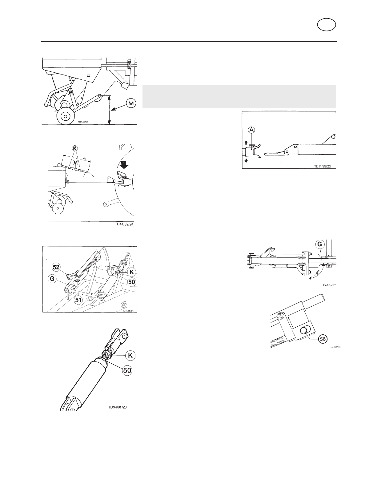
Adjusting drawbar to tractor’s towing coupler
To allow pick-up to work perfectly, the height (M) of coupled trailer must be correctly set
(pick-up pivoting area).
Height (M) = 43 cm
Note: Where the floor is uneven, reduce the measurement by 1 cm (M = 42 cm).
- Park unloaded trailer on even ground
and on jockey wheel.
- Attach trailer coupler (A) to tractor so that
on towed vehicle adequate distance exists
between drive shaft and drawbar.
- Set height (M) from ground to centre of
feeler coupling point by adjusting jockey
wheel.
Drawbar adjustment when equipped with adjusting spindle:
- Loosen lock-nuts (K).
- Twist turnbuckle barrel (V) correspondingly.
- Check height (M) of trailer coupled to tractor.
Observe following when equipped with
hydraulic cylinder:
- Couple trailer to tractor.
- The hydraulic cylinder piston must be
completely inserted.
- Twist nut (51) until clamp frame (52) is at
rightangles (about 90°) to slip rod (G). The
clamp can then be raised.
A slot is located in the fork of the regulating spindle.
- The fastening bolt (56) must make contact with the
inside of the slot.
- Loosen lock-nut (K) on the threaded spindle.
- By twisting the cylinder piston (50), screw the threaded
spindle in or out until the height (M) is achieved.
Slip rod (G) must be able to move in the casing during
the adjustment process (adjust with nut 51).
- Retighten lock-nut (K).
- Twist nut (51) until clamp frame (52) is at rightangles (90°) to slip rod (G).
Pivoting drawbar safety device check
Function of the automatic clamping device:
It prevents the trailer from tipping up during the return trip.
- Adjust by twisting the nut (51) until the clamp frame (52) prevents the trailer from
tipping up through a slight inclination of the slip rod (G).
Maintenance:
Grease pivoting drawbar safety device frequently!
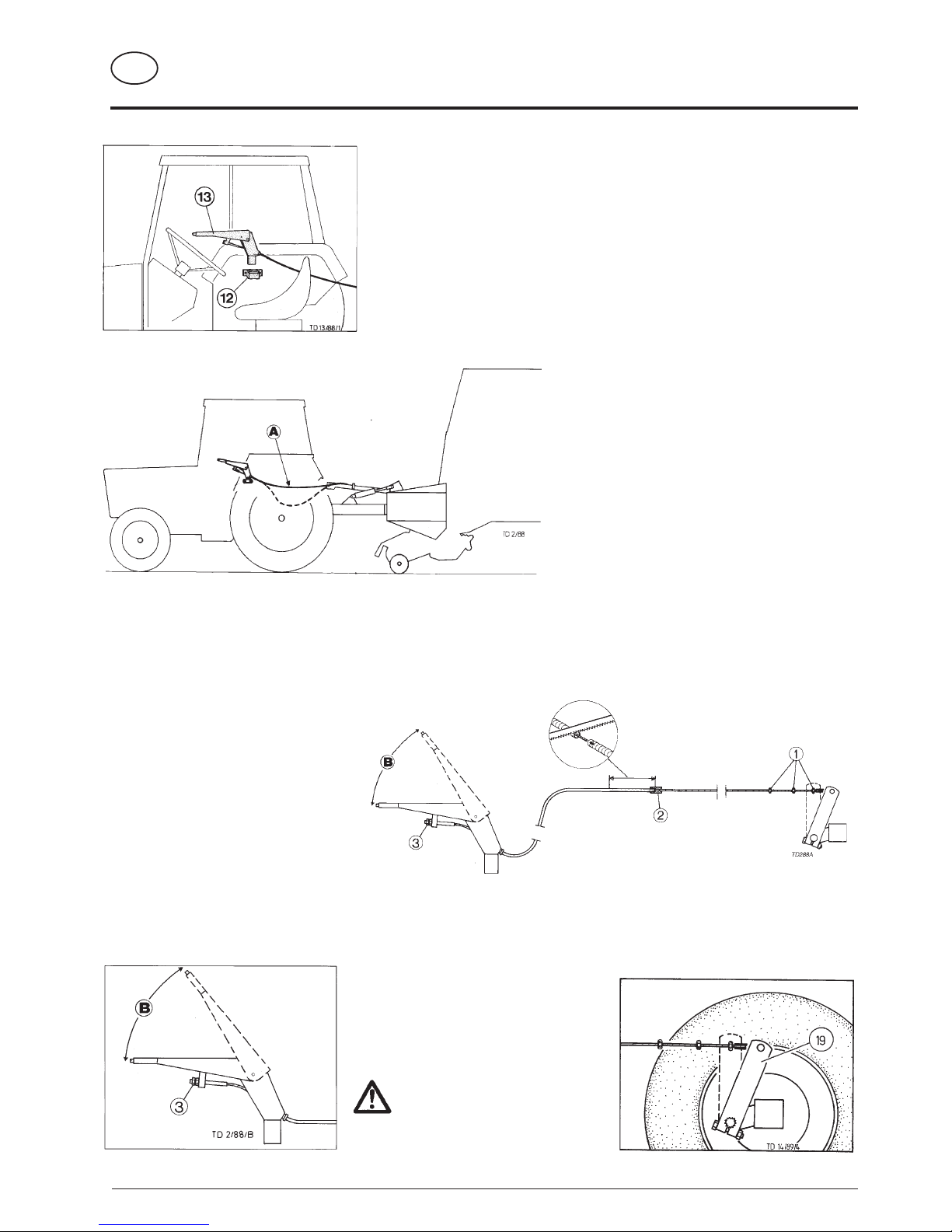
Initial operation
With initial operation install accompanying catch bracket (12) onto mudguard so that
it is within reach and can be seen.
Insert moveable hand break lever (13) onto tractor for every run.
- Carry out brake test.
Attention!
If brake fault occurs, immediately stop tractor and clear fault.
Should the adjustment action on the hand
brake lever no longer be adequate, then with
the help of the notches on the brake cam axle
lever, alter the position of the lever (19)
correspondingly.
The lever adjustment (19) must be
carried out on both sides
simultaneously.
Adaption to tractor
- Loosen cable clamps (1) and unthread the cable through the support (2).
- Shorten bowden cable covering (see diagram) to a point where trouble-free cornering is still is possible.
- Rethread cable and secure with cable clamps.
- Check lever action (B) and adjust with
hexagonal nut (3) if necessary.
Shortening the bowden cable
The extra long brake cable is manufactured to suit
the various designs of different tractor types.
In order to guarantee optimal function of brake
unit, the cable (A) should run in a straight line if
possible.
Brake adjustment
- If brake linings are worn out then brake shoes must be adjusted. This is carried out by turning adjusting nut (3) on hand brake lever.
511 / BREMSANLAGE 9300 GB
- 9 -
GB
BRAKE UNIT
(moveable handbrake)
DRUCKLUFTBREMSE MIT ALB 9400 D (540)
- 10 -
1)
Wunschausrüstung
DRUCKLUFTBREMSANLAGE
D
Ankuppeln der Bremsschläuche
- Beim Ankuppeln der Bremsschläuche ist zu beachten, daß
die Dichtringe der Kupplungsköpfe sauber sind, richtig dichten
und gemäß der
Bezeichnungen “Vorrat”
(Farbe rot) zu “Vorrat”
und “Bremse” (Farbe
gelb) zu “Bremse”
gekuppelt werden.
- Beschädigte Dichtringe
sind zu ersetzen.
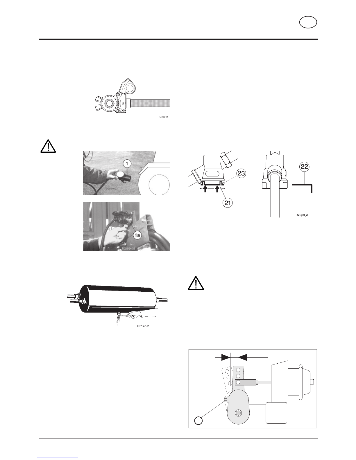
Stromversorgung des ABS (Antiblockiersystem)
1)
Das ABS funktioniert ohne elektrischer Versorgung
nicht.
Vor Beginn der
Fahrt den
Stecker (1) beim
Schlepper
ankuppeln.
• Zum Abstellen des
Wagens den
Stecker an die
Steckdose der
Konsole kuppeln.
Mit dem Schwenkbügel (1a) wird der
Stecker gegen
Lösen gesichert.
- Vor der ersten täglichen Fahrt ist der Luftbehälter zu
entwässern.
- Erst dann abfahren wenn der Luftdruck im Bremssystem 5,0
bar beträgt.
Achtung!
Um ein ordnungsgemäßes Funktionieren der Bremsanlage
zu gewährleisten, sind die Wartungsintervalle sowie die
Bremseinstellung (Hub max. 30 mm) gewissenhaft
einzuhalten.
Pflege und Wartung der Druckluftbremsanlage
Luftbehälterentwässerung
Der Luftbehälter ist täglich zu entwässern. Hierzu ist der
Bolzen am Entwässerungsventil mit Hilfe eines Drahtes in
seitlicher Richtung zu ziehen. Das Entwässerungsventil ist
bei Verschmutzung aus dem Behälter zu schrauben und zu
reinigen.
Leitungsfilterreinigung
Die beiden Leitungsfilter sind je nach Betriebsbedingungen, im
Normalfall etwa alle 3-4 Monate zu reinigen. Zur Reinigung
sind die Sinterfilterpatronen herauszunehmen.
Arbeitsschritte:
a) Verschlußstück (21) an den beiden Laschen hineindrücken
und Schieber (22) herausziehen.
b)Verschlußstück mit O-Ring (23), Druckfeder und
Sinterfilterpatrone herausnehmen.
c) Die Sinterfilterpatrone ist mit Nitro-Reinigungsmittel
auszuwaschen und mit Druckluft auszublasen. Beschädigte
Filterpatronen sind zu erneuern.
d) Beim Zusammenbau in umgekehrter Reihenfolge ist darauf
zu achten, daß der O-Ring (23) nicht in den Führungsschlitz
für den Schieber am Gehäuse verkantet!
Bremseinstellung
Der Kolbenhub an den Bremszylindern darf keinesfalls mehr
als 30 mm aufweisen. Er ist daher von Zeit zu Zeit zu
überprüfen und ggf. nachzustellen.
Achtung!
Lassen Sie allfällige Wartungs- und Reparaturarbeiten
an der Bremsanlage von einer Fachwerkstätte oder
von unserem Kundendienst durchführen.
Für die Schnellläuferachse "300 x 200" gibt es ein
spezielles Wartungshandbuch welches beim
Kundendienst angefordert werden kann.
Einstellung
- Die Einstellung erfolgt durch die Stellschraube (7).
- Der Kolbenhub soll bei Neueinstellung 12 - 15 mm betragen.
TD70/91/4
max. 30 mm Hub
7
DRUCKLUFTBREMSE MIT ALB 9400 D (540)
- 11 -
1)
Wunschausrüstung
DRUCKLUFTBREMSANLAGE
D
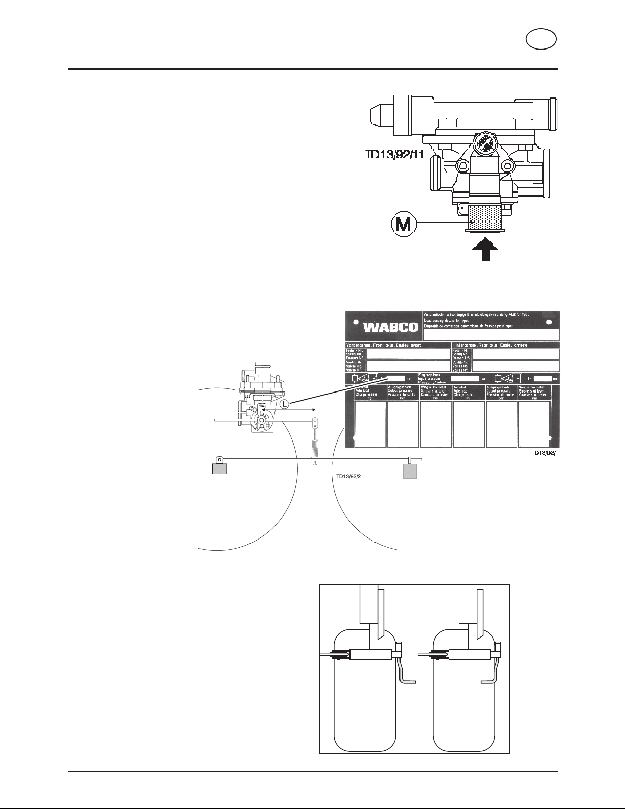
TD13/92/12
Lösestellung am Bremsventil
Die Lösestellung ermöglicht ein Bewegen des Wagens wenn die
Bremschläuche nicht am Schlepper angekuppelt sind.
- Betätigungsknopf (M) bis zum Anschlag hineindrücken. Die Bremse wird
dabei gelöst.
- Betätigungsknopf (M) bis zum Anschlag herausziehen. Der Wagen wird
durch den vom Luftbehälter kommenden Vorratsdruck wieder eingebremst.
- Beim Angekuppeln der Bremsschläuche wird der Betätigungsknopf (M)
durch den vom Zugfahrzeug kommenden Vorratsdruck automatisch
wieder herausgedrückt.
ALB-Regler (Bei Austattung mit automatischem Bremskraftregler)
1)
Mit dem ALB-Regler wird die benötigte Bremskraft, je nach
Beladungszustand des Wagens, automatisch geregelt.
Einstellung
Das Einstellmaß (L) darf nicht verändert werden. Es muß dem Wert
welcher am WABCO Leistungschild angegeben ist entsprechen.
- Vor Antritt der Fahrt ist die Feststellbremse zu lösen und die
Kurbel nach innen zu schwenken.
Abstellen des Wagens
Zum Abstellen wird der Wagen mittels Feststellbremse
eingebremst.
- Bremskraftregler auf “Lösen” stellen und Bremsschläuche
abkuppeln.
COUPLING AND UNCOUPLING THE TRAILER
GB
- 12 -
537 / AN- U. ABKUPPELN 9500 GB
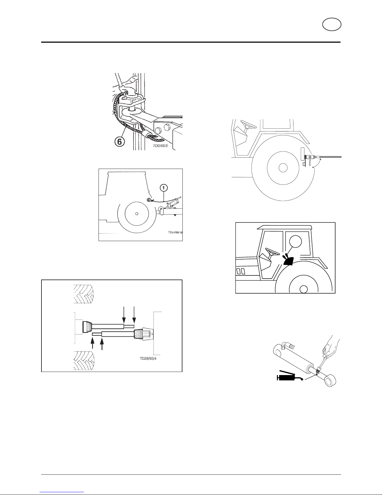
Safety Cable (max. 25 km und max. 4 to zul. Ges Gew.)
- Safety cable (6) to be fitted
correctly to tractor's towing
coupler. (Safeguard against
breakage of trailer coupling
ring or detachment from
tractor.)
Abreißseil (nur bei
Auflaufbremsanlage)
- Bei Anhänger mit
Auflaufvorrichtung das
Abreißseil (1) vom
Handbremshebel am
Traktor verknoten.
(Safeguard against
breakage of trailer
coupling ring or
detachment from
tractor.)
Drive shaft adaption
To shorten the drive shaft see supplement-B!
Hydraulic connection
- Connect hydraulic lines to tractor.
• See also chapter
"HYDRAULIC OPERATION",
"ELECTROHYDRAULIC OPERATION".
Putting into operation
• Before putting the tractor or implement into operation check
vehicle safety (lights, brake unit, protective covering …)!
• Pay attention to correct load distribution during operation!
Uncoupling and parking the trailer
• See also chapter
"SUPPORTING WHEEL", "BRAKE
UNIT", "DRAWBAR".
Important!
Before uncoupling the snap-lock coupler
1. Raise the pick-up.
2. Close shut-off valve on snap-lock coupler (position A).
3. Release pressure on tractor's control unit (ST) and uncouple.
Attention!
• Always park implement so that it is standing safety.
• Secure trailer against rolling away (locking brake, wedges).
Parking in the open
When parking for longer
periods in the open, clean
plunger rods and then coat
with grease.
Garaging for winter
- Thoroughly clean the machine before garaging for winter.
- Apply weather protection.
- Change or top-up gear oil.
- Protect uncoated parts against rusting.
- Grease all lubricating points according to lubrication chart.
FETT
TD49/93/2
A
E
TD31/90/21
ST
- 13 -
HYDRAULIC OPERATION
537 / HYDR.KAB.BED. 9501 GB
GB
Standard position: with an open hydraulic
system
• e.g. a standard tractor with a gear pump.
- The standard basic setting for the shut-off valve (position A)
applies to this type. In this position the shut-off valve is open.
Tip! If the tractor has a closed hydraulic system and the unit
is operating in this position, then the hydraulic oil will heat up
(particularly due to the constant pumping of the maximum
amount of oil).
Remedy: Modify the system on the trailer or decrease the
amount of oil being pumped at the tractor as written below.
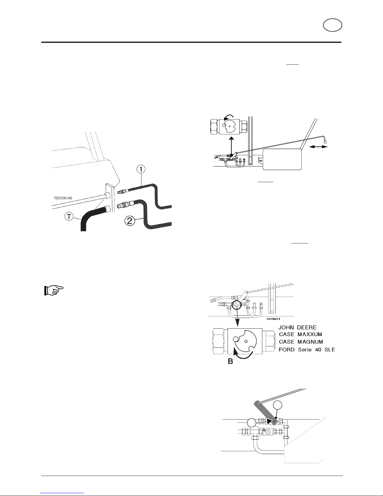
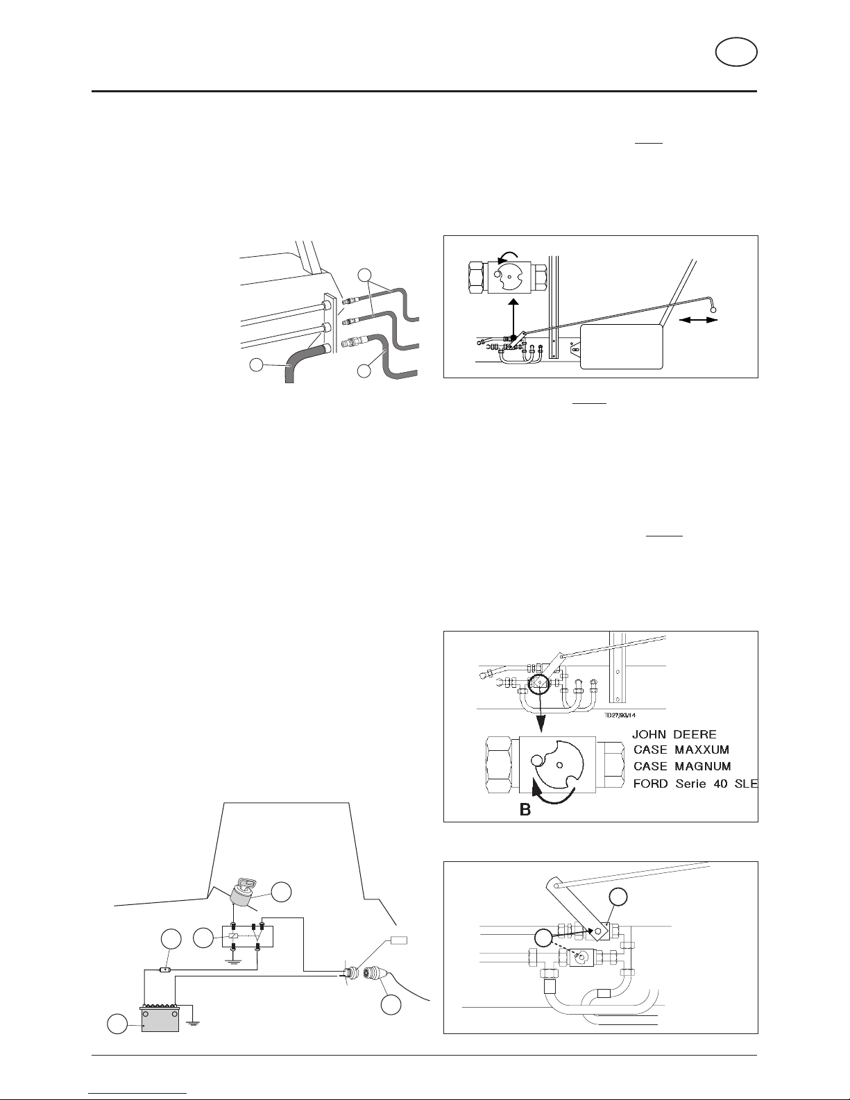
Take care! with tractors with a closed hydraulic
system
• JOHN-DEERE, FORD Serie 40 SLE
CASE-MAGNUM, CASE-MAXXUM,
1. Close the shut-off valve (position B).
2. Dismount lever (7) and fit onto the shut-off valve (11).
Hydraulic connection
Single-action control unit
Should the tractor only have a single-action servo-valve,
then it is absolutely necessary to have an oil-return pipe (T)
fitted by a specialist.
- Connect pressure hose (1) to the single-action control unit.
Couple the oil-return hose (2) (with the greater diameter) to
the tractor’s oil-return system.
Double-action control unit
- Connect pressure line (1) and oil-return pipe (2) (pipe with
the greater diameter is the oil-return pipe).
Note:
If oil should become warm during operation then a
single-action control unit should be connected (see
above).
TD113/91/5
JOHN DEERE
CASE MAXXUM
CASE MAGNUM
FORD Serie 40 SLE
11
7
A
TD7/91/22
EIN
MARCHE
ON
AAN
AUS
ARRET
OFF
UIT
- 14 -
HYDRAULIC OPERATION
537 / HYDR.KAB.BED. 9501 GB
GB
Operation elements Pick-up and hydraulic drawbar
1. Put lever switch "6" into position "I".
2. Put lever switch "7" into position "A".
3. Select desired funktion with lever (9 resp. 10).
4. Engage control valve (ST).
Dry forage extension
1. Put lever switch "6" into position "I".
2. Put lever switch "7" into position "E1".
3. Engage control valve (ST).
Tail gate
1. Put lever switch "6" into position "I".
2. Put lever switch "7" into position "E2".
3. Engage control valve (ST).
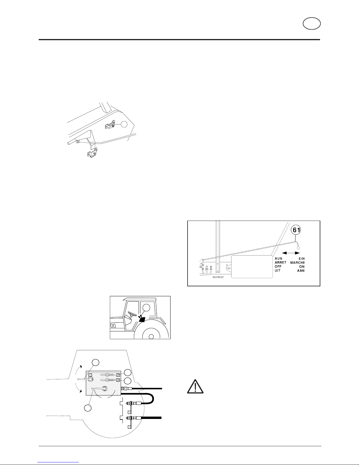
Operation of hydraulic scraper floor drive
Front operation (from the tractor cabin)
1. Shift lever (61) to the "ON" position.
2. Put lever switch (6) into position II (scraper floor drive).
3. Engage or disengage the scraper floor drive with the control
valve (ST).
Rear operation
1. First shift the lever (61) into the "OFF" position.
2. Put lever switch (6) into position II (scraper floor drive).
3. Engage control valve (ST).
4. Switch scraper floor drive "on" or "off" with lever (61).
Safety tips
Please take particular care when the operating
elements on the trailer and the tractor are to be used
simultaneously by more than one person. A
conscientious arrangement should be made by those
concerned before operation.
An example:
Danger of injury arises if a person stands at the rear of the
trailer and somebody in the tractor cabin activates a switching
function (opening the tailgate, switch on the driving gear, ...).
Mounting bracket
• The accompanying bracket (L) is for mounting the hydraulic
switching element in the cabin and is to be installed on the
tractor's mud guard.
Operating elements
• Depending on the trailer's fittings, the order of the operating
elements can differ slightly to the representation shown. For
example, the lever with positions "E1-A-E2" can only be
used on trailers with all extras (e.g. hydraulic drawbar,
hydraulic dry forage extension, tailgate).
The following operating instructions refer to trailers
with all extras
• Shift lever "6" serves to reverse the hydraulic flow between
the the oil cycle of the hydraulic scraper floor drive and the
oil cycle of the preselection levers for the Pick-up lift,
drawbar, etc..
ST = Control valve
0 = 0-position
I + A = Pick-up (9), hydraulic drawbar (10)
II = Hydraulic scraper floor drive
I + E2 = Tail gate
I + E1 = Dry forage extension
P = Pressure hose
T = Runback hose
TD27/93/25
L
A
E1 E2
TD27/93/24
II
0
7
10
P
T
I
6
9
ST
- 15 -
HYDRAULIC OPERATION
537 / HYDR.KAB.BED. 9501 GB
GB
SW DA
TD 18/93/13
W
A
E1 E2
TD27/93/24
II
0
7
10
P
T
I
6
9
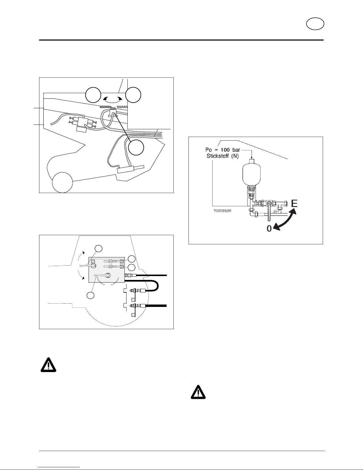
Obstructions when swivelling
- Remove foreign body from swivel range.
• If the cutter bars do not swivel in properly, then a pressure
loss in the cutter unit hydraulic could be the cause.
Remedy by hydraulically filling the reservoir
1. Move lever to position "E" on 3-way valve.
2. Actuate servo-valve. The cutter bar is swivelled out
hydraulically.
3. Leave servo-valve (ST) in the press position for a few
seconds while moving the lever on the 3-way valve to
position "0".
• If obstruction cannot be removed then check gas fill pressure
(100 bar nitrogen) in hydroreservoir.
Alteration of gas container pressure
• This work may only be carried out by customer service or a
specialist.
• In order to reduce or increase the pressure in the gas
container a special filling and checking device is necessary.
Note
• According to manufacturer's information all gas containers
have a slight pressure drop after a certain amount of time.
• The gas loss (nitrogen) amounts to 2-3 % per year.
• After 4-5 years it is recommended that container pressure be
checked and if necessary corrected.
Maintenance
Beware!
No welding, soldering or mechanical works of any
kind may be carried out on the container.
• Hydraulic oil change according to tractor manual.
Dry forage extension
1. Lever (W) in position "DA".
2. Lever on control panel in position "E1".
3. Engage servo-control (ST) on tractor.
Folding extension up or back gradually.
Swivelling cutter unit
Caution!
Do not reach into swivel range of cutter bar
when swivelling in / out.
1. Lever (W) in position "SW".
2. Lever on control panel in position "E1".
3. Engage servo-control (ST) on tractor.
Both cutter bars swivel in resp. out.
• When only one cutter bar is needed for mowing, the lower
cutter bar can be swivelled out using the accompanying
lever (H).
- 16 -
HYDRAULIC OPERATION
537 / HYDR.KAB.BED. 9501 GB
GB
60
A
E1 E2
TD27/93/24
II
0
7
10
P
T
I
6
9
A
E1 E2
TD27/93/24
II
0
7
10
P
T
I
6
9
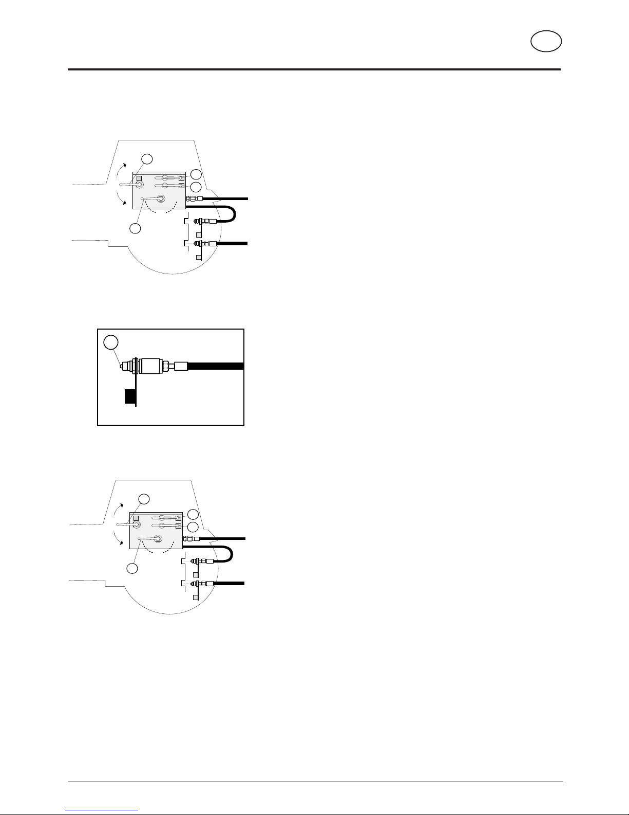
Operation errors
In the operation errors which follow, a problem can arise with the coupling and/
or uncoupling of the hydraulic hoses.
Operation error no. 1
- Pressure hose (P) and runback hose (T) coupled. CORRECT !
- Selector valve (9) open for pick-up operation. CORRECT !
- Lever switch (6) into position I. CORRECT !
- Pick-up in raised condition. WRONG !!!
Result:
Due to the dead weight of the pick-up, pressure builds up in the hydraulic hose
(P). To uncouple the pressure hose is only possible with great effort.
Solution:
Put lever switch (6) into the "0"-position for reoperation. The pressure in the
hydraulic hose can be eased by opening a screw connection.
Caution!
Close the selector valve (9) for pick-up operation before uncoupling and
bring the control valve (S) into "lower" or "float" position.
Operation error no. 2
The wagon with hydraulic drawbar is coupled to the tractor and the jockey
wheel is cranked up.
- Pressure hose (P) and runback hose (T) coupled. CORRECT !
- Selector valve (10) opened for hydraulic drawbar operation. CORRECT !
- Lever switch (6) to pick-up operation (position I). CORRECT !
- The hydraulic drawbar cylinder is not quite retracted
before garaging the wagon. WRONG !!!
Result:
Because of the load resting on the cylinders, excess pressure builds up in the
hydraulic hose (P). Uncoupling of the hose is not possible.
Solution:
Completely retract the hydraulic drawbar cylinder or garage the wagon on the
jockey wheel so that the load on the cylinder is eased.
Caution!
Do not operate the hydraulic drawbar while the wagon is supported on the
jockey wheel.
0200-GB ELEK-HYD_537
- 17 -
GB
ELECTROHYDRAULIC OPERATION
12V=
+
-
8
11
9
7-POL
"54g"
"31"
10
12
TD 18/93/11
86 86a 87
85 30
A
TD7/91/22
EIN
MARCHE
ON
AAN
AUS
ARRET
OFF
UIT
Hydraulic connection
Single-action control unit
Should the tractor only have a single-action servo-valve,
then it is absolutely necessary to have an oil-return pipe (T)
fitted by a specialist.
- Connect pressure hose (1)
to the single-action control
unit.
- Couple the oil-return hose
(2) (with the greater
diameter) to the tractor’s
oil-return system.
Double-action control unit
- Connect pressure line (1) and oil-return pipe (2) (pipe with
the greater diameter is the oil-return pipe).
Note:
If oil should become warm during operation then a singleaction control unit should be connected (see above).
Power supply
• Power (8) 12V is supplied via relay (9) connected to the
ignition (10).
• Lead diameter 2,5 mm2, fuse 16A (11).
• Power for the trailer is supplied via socket "54g" (+pole) and
"31" (-pole).
This modification is to be carried out only by
specialized workshops.
• Don’t connect directly to ignition (danger of fire and/or
damage of electrical equipment).
Establishing electric connection
- After completing above mentionnned work connect 7-pole
plug from trailer with socket.
- Check lights.
Standard position: with an open hydraulic
system
• e.g. a standard tractor with a gear pump.
- The standard basic setting for the shut-off valve (position A)
applies to this type. In this position the shut-off valve is open.
Tip! If the tractor has a closed hydraulic system and the unit
is operating in this position, then the hydraulic oil will heat up
(particularly due to the constant pumping of the maximum
amount of oil).
Remedy: Modify the system on the trailer or decrease the
amount of oil being pumped at the tractor as written below.
Take care! with tractors with a closed hydraulic
system
• JOHN-DEERE, FORD Serie 40 SLE
CASE-MAGNUM, CASE-MAXXUM,
- Close the shut-off valve (position B).
- Dismount lever (7) and fit onto the shut-off valve (11).
2
T
TD 18/93/10
1
11
TD27/93/16
JOHN DEERE
CASE MAXXUM
CASE MAGNUM
FORD Serie 40 SLE
7

0200-GB ELEK-HYD_537
- 18 -
GB
ELECTROHYDRAULIC OPERATION
Installation and check of the
electrohydraulic operation
- Mount supplied
bracket (13) for the
electrohydraulic
operating with two
hexagon screws
within driver’s vision
and reach in tractor
cabin.
- Insert front control
panel (14) in bracket (13).
Operation
- Preselect desired function on control panel. Switch engages.
- Preselected function is
engaged using servocontrol (ST) on tractor.
Note:
- If tractor is to be parked with implement
attached, electro-hydraulic operation
lever is to be shifted into neutral
position "C".
This prevents battery discharge.
Safety tips
Please take particular care when the operating
elements on the trailer and the tractor are to be used
simultaneously by more than one person. A
conscientious arrangement should be made by those
concerned before operation.
An example:
Danger of injury arises if a person stands at the rear of the
trailer and somebody in the tractor cabin activates a switching
function (opening the tailgate, switch on the driving gear, ...).
Pivoting drawbar
1. Lever on control panel in position "A".
2. Engage servo-control (ST) on tractor.
Attention!
Do not engage pivoting drawbar when
implement is standing on supporting wheel.
Tailgate
1. Lever on control panel in position "D".
2. Engage servo-control (ST) on tractor.
Automatic unlocking, raising/lowering and
shutting of tailgate.
Scraper floor reverse run (KR)
Front operation
1. Shift lever (61) to the "ON" position.
2. Lever on control panel in neutral position "C".
3. Engage servo-control (ST) on tractor.
Rear operation
1. First shift the lever (61) into the "OFF"
position.
2. Lever on control panel in neutral position
"C".
3. Engage servo-control (ST) on tractor.
4. Switch scraper floor drive "on" or "off" with lever (61).
Pick-up
1. Lever in position "E".
2. Engage servo-control (ST) on tractor.
Raising or lowering pick-up.
I n doing so loading unit operation and pick-
up are automatically switched on or off.
Dry forage extension
1. Lever on control panel in position "B".
2. Engage servo-control (ST) on tractor.
Folding extension up or back gradually.
TD 18/93/9
A
BC
D
E
KB - KR
KR
ST

0200-GB ELEK-HYD_537
- 19 -
GB
ELECTROHYDRAULIC OPERATION
SW DA
TD 18/93/13
W
TD 18/93/9
A
BC
D
E
Dry forage extension
- Lever (W) in position "DA".
- Lever on control panel in position "B".
- Engage servo-control (ST) on tractor.
Folding extension up or back gradually.
Swivelling cutter unit
Caution!
Do not reach into swivel range of cutter bar
when swivelling in / out.
- Lever (W) in position "SW".
- Lever on control panel in position "B".
- Engage servo-control (ST) on tractor.
Both cutter bars swivel in resp. out.
• When only one cutter bar
is needed for mowing, the
lower cutter bar can be
swivelled out using the
accoompanying lever (H).
Obstructions when swivelling
- Remove foreign body from swivel range.
• If the cutter bars do not swivel in properly, then a pressure
loss in the cutter unit hydraulic could be the cause.
Remedy by hydraulically filling the reservoir
- Move lever to position "E" on 3-way valve.
- Actuate servo-valve. The cutter bar is swivelled out
hydraulically.
- Leave servo-valve (ST) in the press position for a few
seconds while moving the lever on the 3-way valve to
position "0".
• If obstruction cannot be removed then check gas fill pressure
(100 bar nitrogen) in hydroreservoir.
Alteration of gas container pressure
• This work may only be carried out by customer service or a
specialist.
• In order to reduce or increase the pressure in
the gas container a special filling and checking
device is necessary.
Note
• According to manufacturer's information all
gas containers have a slight pressure drop
after a certain amount of time.
• The gas loss (nitrogen) amounts to 2-3 % per year.
• After 4-5 years it is recommended that container pressure be
checked and if necessary corrected.
Maintenance
Beware!
No welding, soldering or mechanical works of
any kind may be carried out on the container.
• Hydraulic oil change according to tractor manual.
• Before welding on trailer disconnect all plugs from tractor
and disconnect trailer.

0200-GB ELEK-HYD_537
- 20 -
GB
ELECTROHYDRAULIC OPERATION
Trouble shooting
Beware!
Whenever eliminating trouble it is
essential to turn off power take-off.
During all these raising and/or lowering,
turning on and off processes mind
safety distances!
Maintenance
• Hydraulic oil change according to tractor manual.
• Before welding on trailer disconnect all plugs from tractor and disconnect trailer.
Lowering the pick-up
• Loosen lock nut(* (G).
• Screw in screw (H) on valve "Y1".
• Shift servo-control (ST) on tractor to lowering or "floating" position.
Pick-up is then lowered.
• Screw out screw (H) and lock with nut
(*
(G).
Raising the pick-up
• If valve (Y5) is installed, upper control cock at rear of implement must
be shifted to position "B".
• Loosen lock nut(* (G).
• Screw in screw (H) on valve "Y1".
• Shift servo-control (ST) on tractor to raising position. Pick-up is then
raised.
• Screw out screw (H) and lock with nut
(*
(G).
Lowering the pivoting drawbar
• Loosen lock nut(* (G).
• Screw in screw (H) on valve "Y2".
• Shift servo-control (ST) on tractor to lowering or "floating" position.
Pivoting drawbar is then lowered.
• Screw out screw (H) and lock with nut
(*
(G).
Raising the pivoting drawbar
• If valve (Y5) is installed, upper control cock at rear of implement must
be shifted to position "B".
• Loosen lock nut
(*
(G).
• Screw in screw (H) on valve "Y2".
• Shift servo-control (ST) on tractor to raising position. Pivoting drawbar
is then raised.
• Screw out screw (H) and lock with nut
(*
(G).
Emergency handling of hydraulic valves
in case of power break down
Lowering the dry forage extension
• Loosen lock nut(* (G).
• Screw in screw (H) on valve "Y3".
• Shift servo-control (ST) on tractor to lowering or "floating"
position. Dry forage extension is then lowered.
• Screw out screw (H) and lock with nut
(*
(G).
Raising the dry forage extension
• If valve (Y5) is installed, upper control cock at rear of implement
must be shifted to position "B".
• Loosen lock nut(* (G).
• Screw in screw (H) on valve "Y3".
• Shift servo-control (ST) on tractor to raising position. Dry forage
extension is then raised.
• Screw out screw (H) and lock with nut
(*
(G).
Opening the tailgate
• If valve (Y5) is installed, upper control cock at rear of implement
must be shifted to position "B".
• Loosen lock nut
(*
(G).
• Screw in screw (H) on valve "Y4".
• Shift servo-control (ST) on tractor to raising position. Tailgate
then opens.
• Screw out screw (H) and lock with nut
(*
(G).
Closing the tailgate
• Loosen lock nut(* (G).
• Screw in screw (H) on valve "Y4".
• Shift servo-control (ST) on tractor to lowering or "floating"
position. Tailgate then closes.
• Screw out screw (H) and lock with nut
(*
(G).
Y2
Y4
Y1
Y3
TD 18/93/14
Y5
ST
G
H
024-02-04
H
Variation 1
(* only for variation 1

GB
ELECTROHYDRAULIC COMFORT OPERATION
- 21 -
9500-GB ELEK.HYD.KOMF. (511)
Hydraulic connection
Single-action control unit
Should the tractor only have a single-action servo-valve,
then it is absolutely necessary to have an oil-return pipe
(T) fitted by a specialist.
- Connect pressure hose (1) to the single-action control
unit.
- Couple the oil-return hose (2) (with the greater diameter)
to the tractor’s oil-return system.
Double-action control unit
- Connect pressure line (1) and oil-return pipe (2) (pipe with
the greater diameter is the oil-return pipe).
Note:
If oil should become warm during operation then a singleaction control unit should be connected (see above).
Standard position: with tractors with an open
hydraulic system
• e.g. a standard tractor with a gear pump.
- The position of the slotted screw (7) is set in the factory. The
slotted screw (7) must be screwed out to the point where the
screw head is level with the
surface (6) of the hydraulic
block.
Tip! If the tractor has a closed hydraulic system and the unit
is operating in this position, then the hydraulic oil will heat up
(particularly due to the constant pumping of the maximum
amount of oil).
Remedy: Modify the system on the trailer or decrease the
amount of oil being pumped at the tractor as written below.
Take care! with tractors with a closed hydraulic
system
• JOHN-DEERE, FORD Serie 40 SLE
CASE-MAGNUM, CASE-MAXXUM
Before coupling, the slotted screw (7) on
the hydraulic block is to be screwed
completely in.
Power supply
• Power (8) 12V is supplied via relay (9) connected to the ignition
(10).
• Lead diameter 2,5 mm2, fuse 16A (11).
• Power for the trailer is supplied via socket "54g" (+pole) and
"31" (-pole).
This modification is to be carried out only by specialized
workshops.
• Don’t connect directly to ignition.
• Don’t connect directly to battery (danger of fire and/or
damage of electrical equipment).
Establishing electric connection
- After completing above mentionnned work connect 7-pole
plug from trailer with socket.
- Check lights.
TD 20/94/5
7
JOHN DEERE
CASE MAXXUM
CASE MAGNUM
FORD Serie 40 SLE
Standard-
position
TD20/94/6
JOHN DEERE
CASE MAXXUM
CASE MAGNUM
FORD Serie 40 SLE

GB
ELECTROHYDRAULIC COMFORT OPERATION
- 22 -
9500-GB ELEK.HYD.KOMF. (511)
Installation and check of comfort operation
Installation
- Mount supplied bracket
(13) for comfort operating
with two hexagon screws
within driver’s vision and
reach in tractor cabin.
- Insert front control panel
(14) in bracket.
Check switch-off functions
1. The scraper floor drive must be switched off.
• The press-button (16) on the control panel must not be depressed
(OFF- position).
• Likewise, the press-
button (32) in the switch
box located rear left of
the trailer must not be
depressed (OFFposition).
Control lamp:
The control lamp which is intergrated in the press-button
(16) lights up when either of the press-buttons (16, 32) is depressed
(scraper floor drive is switched on).
Safety tips
Please take particular care when the operating elements on the
trailer and the tractor are to be used simultaneously by more than
one person. A conscientious arrangement should be made by
those concerned before operation.
An example:
Danger of injury arises if a person stands at the rear of the trailer and
somebody in the tractor cabin activates a switching function (opening
the tailgate, switch on the driving gear, ...).
2. Operating switch
- All switches, except switch (19)
which is for the Pick-up lift, are
to be briefly switched down (B)
(switch off or lower position).
Pick-up lift
• Moving the switch (19) down (B) lowers the
Pick-up.
Caution!
If the lever (43) is in the "ON"
position then the loading unit and
Pick-up drive will automatically
switch on when lowering.
Therefore always stay at a safe
distance if the drive shaft is
coupled to the tractor and the p.t.o.
drive is switched on.
3. Engage control valve.
- Move lever (ST) to "ON" position and secure.
In so doing the trailer’s control block is supplied
with oil.
- By using a switch (15, 20, …) on the control panel
the relative hydraulic function takes place.
ST

GB
ELECTROHYDRAULIC COMFORT OPERATION
- 23 -
9500-GB ELEK.HYD.KOMF. (511)
Functions
Pick-up switch (19)
- Pushed down (B) - pick-up drops and
remains in floating position.
- Pushed up (A) - pick-up rises (feed
and pick-up drive stop automatically).
Caution!
If the lever (43) is in the "ON" position then the
loading unit and Pick-up drive will
automatically switch on when lowering.
Therefore always stay at a safe distance if the
drive shaft is coupled to the tractor and the
p.t.o. drive is switched on.
Hydraulic drawbar switch (26)
- Pushed up (A) - drawbar rises.
- Pushed down (B) - drawbar drops.
On the road hydraulic drawbar cylinder must be
completely retracted.
Rear gate lifting switch (15)
- Switch (15) pushed up (A) - rear gate
is released and opened.
- Switch (27) pushed down (B) - rear
gate is lowered.
Persons to leave pivoting area!
Attention!
While lowering switch stays turned on. After locking
rear gate switch has to be brought to position "0".
Scraper floor drive push-button front (16) and rear
(32)
- When pressing pushbutton (32/16) it
remains in position (C)
and moving floor drive
is turned on.
Integrated control
lamp (16) at front
control panel lights up.
- Pressing the push-button again turns off the moving floor
drive (D).
• The control lamp in push-button (16) must go out.
If the control lamp remains lit up nevertheless, then the
second push-button (32) is still depressed and the scraper
floor is still operating!
General hints
Selecting another function in addition to the moving
floor feed will automatically interrupt the moving
floor feed.

103 / SPEICHER 9400 GB
ELECTROHYDRAULIC COMFORT OPERATION
- 24 -
GB
Dry forage extension
- Lever (W) in position "DA".
- Move switch (20) to position "A".
Dry forage extension folds up.
- Move switch (20) to position "B".
Dry forage extension folds down.
Swivelling cutter unit
Caution!
Do not reach into swivel range of cutter bar
when swivelling in / out.
- Lever (W) in position "SW".
- Move switch (20) to position "B".
Both cutter bars swivel out.
- Move switch (20) to position "A".
Both cutter bars swivel in.
• When only one cutter bar
is needed for mowing, the
lower cutter bar can be
swivelled out using the
accompanying lever (H).
Obstructions when swivelling
- Remove foreign body from swivel range.
• If the cutter bars do not swivel in properly, then a pressure
loss in the cutter unit hydraulic could be the cause.
Remedy by hydraulically filling the reservoir.
- Move lever to position "E" on 3-way valve.
- Actuate servo-valve (ST).
- Move switch (20) on control panel to position "B".
The cutter bar is swivelled out hydraulically.
- Leave switch (20) and servo-valve (ST) in the press position
for a few seconds while moving the lever on the 3-way valve
to position "0".
• If obstruction cannot be removed then check gas fill pressure
(100 bar nitrogen) in hydroreservoir.
Alteration of gas container pressure
• This work may only be carried out by customer service or a
specialist.
• In order to reduce or increase the pressure in
the gas container a special filling and checking
device is necessary.
Note
• According to manufacturer's information all
gas containers have a slight pressure drop
after a certain amount of time.
• The gas loss (nitrogen) amounts to 2-3 % per year.
• After 4-5 years it is recommended that container pressure be
checked and if necessary corrected.
Maintenance
Beware!
No welding, soldering or mechanical works of
any kind may be carried out on the container.
• Hydraulic oil change according to tractor manual.
• Before welding on trailer disconnect all plugs from tractor
and disconnect trailer.
DASW
W
TD20/94/11

103 / ELEK-STÖRUNG 9400 GB
GB
ELECTROHYDRAULIC OPERATION
- 25 -
Trouble shooting
Beware!
Whenever eliminating trouble it is essential to
turn off power take-off.
No welding, soldering or mechanical works of
any kind may be carried out on the gas
container.
During all these raising and/or lowering,
turning on and off processes mind safety
distances!
Emergency handling of hydraulic valves in
case of power break down ( - Baujahr 1997)
TD 20/94/10
Y6 Y5
Y3
Y2
Y4
Y1
G
H
DASW
W
TD20/94/11
Lowering the pick-up
• Loosen lock nut (G).
• Screw in screw (H) on valve "Y1".
• Shift servo-control (ST) on tractor to lowering or "floating"
position. Pick-up is then lowered.
• Screw out screw (H) and lock with nut (G).
Raising the pick-up
• Loosen lock nut (G).
• Screw in screw (H) on valve "Y1".
• Shift servo-control (ST) on tractor to raising position. Pick-up
is then raised.
• Screw out screw (H) and lock with nut (G).
Lowering the pivoting drawbar
• Loosen lock nut (G).
• Screw in screw (H) on valve "Y2".
• Shift servo-control (ST) on tractor to lowering or "floating"
position. Pivoting drawbar is then lowered.
• Screw out screw (H) and lock with nut (G).
Raising the pivoting drawbar
• Loosen lock nut (G).
• Screw in screw (H) on valve "Y2".
• Shift servo-control (ST) on tractor to raising position. Pivoting
drawbar is then raised.
• Screw out screw (H) and lock with nut (G).
Lowering the dry forage extension
• Lever (W) in position "DA".
• Loosen lock nut (G).
• Screw in screw (H) on valve "Y3".
• Shift servo-control (ST) on tractor to lowering or "floating"
position. Dry forage extension is then lowered.
• Screw out screw (H) and lock with nut (G).
Raising the dry forage extension
• Lever (W) in position "DA".
• Loosen lock nut (G).
• Screw in screw (H) on valve "Y3".
• Shift servo-control (ST) on tractor to raising position. Dry
forage extension is then raised.
• Screw out screw (H) and lock with nut (G).
Swivelling the cutter unit out
• Shift servo-control (ST) on tractor to locking position.
• Lever (W) in position "SW".
• Loosen lock nut (G).
• Screw in screw (H) on valve "Y3".
• Shift servo-control (ST) on tractor to raising position. Cutter
unit then swivels out.
• Screw out screw (H) and lock with nut (G).
Swivelling the cutter unit in
• Lever (W) in position "SW".
• Loosen lock nut (G).
• Screw in screw (H) on valve "Y3".
• Shift servo-control (ST) on tractor to lowering or "floating"
position. Cutter unit then swivels in.
• Screw out screw (H) and lock with nut (G).
Opening the tailgate
• Loosen lock nut (G).
• Screw in screw (H) on valve "Y4".
• Shift servo-control (ST) on tractor to raising position. Tailgate
then opens.
• Screw out screw (H) and lock with nut (G).
Closing the tailgate
• Loosen lock nut (G).
• Screw in screw (H) on valve "Y4".
• Shift servo-control (ST) on tractor to lowering or "floating"
position. Tailgate then closes.
• Screw out screw (H) and lock with nut (G).
Switching on scraper floor drive
• Set the button in position „Y6“.

9800-GB ELEK-STÖRUNG (103)
GB
ELECTROHYDRAULIC OPERATION
- 26 -
Trouble shooting
Beware!
Whenever eliminating trouble it is
essential to turn off power take-off.
No welding, soldering or mechanical
works of any kind may be carried out on
the gas container.
During all these raising and/or lowering,
turning on and off processes mind safety
distances!
Emergency handling of hydraulic valves in case of
power break down ( + Baujahr 1998)
DASW
W
TD20/94/11
Lowering the dry forage extension
• Lever (W) in position "DA".
• Shift servo-control (ST) on tractor to lowering or "floating"
position. Dry forage extension is then lowered.
Raising the dry forage extension
• Lever (W) in position "DA".
• Shift servo-control (ST) on tractor to raising position. Dry
forage extension is then raised.
Swivelling the cutter unit out
• Lever (W) in position "SW".
• Shift servo-control (ST) on tractor to raising position.
Cutter unit then swivels out.
Swivelling the cutter unit in
• Lever (W) in position "SW".
• Shift servo-control (ST) on tractor to lowering or "floating"
position. Cutter unit then swivels in.
Y4 Y3
Y2 Y1
Y6 Y5
Y5 Y2 Y2
AB
PT
Standard
Y3Y5 Y3
Y4
Y6
Y4Y5
Y1Y1Y5
495.690
(John Deere
Case Maxum
Case Magnum
Ford-Serie 40 LS
. . . . . )

Starting the loading process
1. Move control lever (43) for pick-up and conveyor drive
to "ON" position.
2. Switch on tractor’s
p.t.o..
3. Lower pick-up.
Take care! Doing this
automatically switches on
the Pick-up and press
drive.
When switch lever „43“ is
in the „OFF“ position then
the Pick-up and press will
not be activated.
4. When loading, switch control unit (ST)
to "lower" or "float" and in doing so
the pick-up regulates itself to the
uneven ground.
5. Observe p.t.o.-r.p.m.
• Load using average p.t.o.-r.p.m. (400-450 rpm).
To observe during the loading process!
• Only raise pick-up when loading channel is empty.
• When driving
through curves
reduce motor
r.p.m.
• When driving
through sharp
curves switch off
p.t.o. and raise
pick-up.
• Avoid uneven
loads! Important
because of
possible drawbar
overloading (see
details on the
drawbar
concerning permitted support load).
• To optimumly fill the loading space, switch the scraper floor on
briefly (do not let it run continually).
• Watch the trailer fill indicator
(1
.
• Observe the permitted axle load and total weight!
Finishing the loading process
1. Raise Pick-up.
Doing this automatically switches off the Pick-up and conveyor
drive.
2. Move the switch lever „43“ to the „OFF“ position.
This position is for your safety. Doing this prevents the Pick-up
and press from being unintentionally activated, e.g. when lowering
the Pick-up while the p.t.o. is running.
Trailer fill indicator
(1
A = not full; B = full
Switch off scraper floor drive when
indicator is in the „B“ position.
Safety tips:
• Turn off the drive motor and take off the drive shaft
when carrying out all adjustment work.
• Faults in the Pick-up area are to be eliminated
only when the drive motor has been stopped.
Adjusting the pick-up
1. Raise pick-up slightly and secure with adjusting struts (51),
left and right sides in same position.
2. Secure with linch pin.
High adjustment:
with tall stubble and
extremely uneven
ground.
Low Adjustment:
with short green
fodder and even
ground.
Impact deflector adjustment (52)
- In low position (T) for small swaths and short fodder.
- In high position (H)
for high swaths.
Loading process in general
Important tips:
• A transfer, which is located on the drawbar, tells which
p.t.o.-r.p.m. (540 rpm/1000 rpm) your trailer is equipped
for.
• Therefore take care that a drive shaft with the correct
overload safety is used (see spare parts list), so that no
unnecessary damage is caused to the trailer through
overloading.
• Always adapt driving speed to the surroundings.
• Avoid making sudden curves when driving through hills and
valleys, and when transversing slopes (danger of tipping).
Loading green fodder
- As a rule green fodder is collected in swaths.
- Cut swaths collected are always stalk heads.
- Set deflector (52) low position (T).
Loading dry fodder
- Correct dry fodder collection is in swaths.
- Don’t make swaths too small in order to save loading time.
- Set deflector (52) in the position (H).
A
B
TD75/90/18
(1 = only when available
ST
9700-GB BELADEN (107)
LOADING THE TRAILER
- 27 -
GB

- 28 -
CUTTER UNIT
GB
103 / SCHNEIDWERK 9500 GB
Swivelling cutter unit in and out
Lever (H) is located underneath front collapsible
side guard.
- Insert lever (H) into hexagonal socket on cutter
bar.
- Push lever forward (position A) and in so doing
cutter unit swivels out.
- Push lever backward (position B) and in so doing
cutter unit swivels in.
Safety points
• Turn engine off when adjustment, service and repair work is to
be done.
• Do not work under the machine without safe support.
Folding cutter bar down
• Only necessary for maintenance and conversion work!
1. Swivel cutter bar out using lever (H)
lever should be in
position A.
2. Remove lever (H) from
socket and secure it in
position B.
3. Loosen linch pin (K)
on right side of trailer
first, then remove
securing bracket (L).

- 29 -
CUTTER UNIT
GB
103 / SCHNEIDWERK 9500 GB
Quick-insert cutters (M)
Handling quick-insert cutters
- With a low loading trailer, quick-insert cutters (M) are
accessible from loading area after folding cover plate (A) up.
- With a high loading trailer, quick-insert cutters (if existing)
are accessible from underneath.
Swivelling out a quick-insert cutter
1. Push leaf spring (F) away to the side.
2. Pull cutter (M) down gently and remove.
4. Lift cutter unit using lever (H) to relieve load.
5. Pull out linch pin and remove securing bracket (L).
Caution!
Cutter unit folds down automatically under its
own weight.
Take care that your hand is not crushed between
lever and floor!
Folding two cutter bars down
- As described previously, swivel upper cutter bar down first
then lower cutter bar.

- 30 -
CUTTER UNIT
GB
103 / SCHNEIDWERK 9500 GB
Cutter bar
Removal and installation of a cutter
Removing a cutter
from a swivelled out
cutter bar.
1. Pull catch lever (R)
down using
screwdriver.
2. Swivel cutter up
(position A) and remove
by pulling backwards.
Removing a cutter from
a swivelled up cutter bar.
Cutter installation
- Take care that catch lever
caster rests properly in cutter
recess.
Removing a quick-insert cutter
1. Push leaf spring (F) away to the side and swivel
cutter out.
2. Push lower leaf spring (U) away to the side and
remove complete individual cutter by sliding down.
Installing a quick-insert cutter
- When installing complete individual cutter ensure
that both leaf springs (F/U) catch.

- 31 -
CUTTER UNIT
GB
103 / SCHNEIDWERK 9500 GB
Maintenance
Well ground cutters save energy and
provide good cutting quality.
Safety points
• Turn engine off when
adjustment, service and
repair work is to be done.
• Do not work under the machine without safe support.
• Wear protective glasses.
Caution!
Only grind the smooth side of the cutter
Sensible grinding without heating (tarnishing) the cutter
guarantees a long life.
Cutter safeguard
Regularly cleaning is recommended to guarantee the perfect
function of the cutter safeguard.
• Clean pressure springs with high pressure cleaner.
• Oil cutter and safeguard element
before winter storage!
Direct grinding of cutter on cutter bar
1. Swivel cutter bar down to the ground.
2. Grind cutter in installed position with hand grinder.
Grinding of removed cutters
- Remove individual cutter and grind with hand grinder.

- 32 -
GB
DRY FORAGE EXTENSION
511 / DÜRRFUTTERAUFBAU 9500 GB
Mechanical adjustment
• Instead of the mechanical adjusting unit the trailer
can also be fitted with a hydraulic one (see the
relevant chapter in this operating manual).
Folding dry forage extension up/down
1. Unlock right support strut (RS).
2. Attach tailgate raising lever (A) to dry forage extension.
3. Unlock left support strut (LS) while holding lever (A)
firmly.
Take care!
The dry forage extension can fold together
itself a little under its own weight. Be aware
of lever's (A) and support strut's jib range.
4. Always hold lever (A) firmly when adjusting and
manoeuvre extension slowly!
5. Secure left support strut (LS) first, then right support
strut (RS).
6. Detach lever (A).
D = Dry forage position
G = Dried silage and green forage position
Sliding plates (56)
- With low entrances it may be necessary to remove both sliding
plates (56).
Top ropes
- When loading chaff, remove top ropes.
Safety tip
Adjusting the relieving spring
The operating force on lever (A) should not exceed 25 kp
(245 N).
From there adjust the relieving spring tension (Z) accordingly.
D
G
TD34/91/12
56
TD14/89/35a
TD56/94/7
Z
LS
max.
25 kp
A

GB
TAIL GATE
- 33 -
103 / RÜCKWAND 9500 GB
Hydraulic opening and closing of the tail gate
Nobody should be within the swinging
range of the tail gate when opening
and closing!
Do not stand underneath the raised tail
gate!
- Opening and closing is effected
hydraulically from the tractor seat.
In doing so, the locking hooks (58) are
unlocked and locked automatically.
Unloading with lowered top frame
- Lock tubular frame against raising (clip left and right into position B).
- The tail gate swings backwards when
opening.
Unloading with raised top frame
- Unlock tubular frame to raise (clip left and right
into position A).
- The tail gate and the tubular frame swing all
the way to the top when opening.
Adjustments
• So that the opening and closing of the tail gate
functions properly, set the adjusting screws
left and right according to the following
sequence.
- Turn the hexagonal screw (57) until the lower
pipe of the tail gate fits into the slotted plate (K).
- Set a gap (1-3 mm) by means of the hexagonal
screw (56).
- Slip the yoke end of the frame (G) from the pin
and turn it until the hooks (58) rest, without
play, on the pipe.
- Check that all lock nuts are firmly fixed.
TD79/90/38
B
TD7/91/11a
A
TD79/90/39

General
Check regularly that wheel nuts are firmly tightened ( see table for screw starting torque)!
Attention!
After the first 10 hours of operation retighten wheel nuts.
- If a wheel has been changed retighten the wheel nuts after 10 hours of operation also.
- Pay attention to correct tyre pressure!
- Regularly check tyre air pressure
according to the chart.
Danger of bursting exists when pumping
up tyres and with high tyre pressure!
Tyre size Ply rating Air pressure
(bar)
Starting torque Highest permitted speed
3,50-6 4 PR 3,00
4,00-6 4 PR 2,50
4,00-8 4 PR 2,50
5,00-8 6 PR 4,00
5,00-15 AM (M137C) 1,00
7,00-12 6 PR 3,00
10,0/80-12 6 PR 3,00 200 Nm
10,0/80-12 8 PR 4,20 200 Nm
10,0/75-15,3 6 PR 3,10 200 Nm
10,0/75-15,3 8 PR 4,20 320/200** Nm
10,0/75-15,3 10 PR 5,20 320/200** Nm
11,5/80-15,3 8 PR 3,70 320/200** Nm
11,5/80-15,3 10 PR 4,60 320/200** Nm
11,5/80-15,3 12 PR 5,00 320/200** Nm
12,0-18 5,70 320 Nm
13,0/55-16 10 PR 3,90 320 Nm
13,0/55-16 12 PR 4,70 320 Nm
15,0/55-17 8 PR 2,90 320/200** Nm
15,0/55-17 10 PR 3,50 320/200** Nm 30 km
15,0/55-17 12 PR 4,30 320/200** Nm
15 x 6 - 6 4 PR 1,00
15 x 6 - 6 4 PR 1,20
16 x 6,5-8 4 PR 1,50
19,0/45-17 10 PR 3,00 320 Nm
205 R 14 C 8 PR 3,00 320 Nm
205 R 14 C* 8 PR 4,25 320 Nm
325/65 R 18 16 PR 5,70 320 Nm
335/65 R 18 XP 27 5,0 320 Nm
500/40-17 10 PR 2,90 320 Nm 40 km
500/50-17 10 PR 2,75 320 Nm 30 km
500/50-17 10 PR 3,75 320 Nm 40 km
500/50-17 14 PR 5,0 320 Nm 65 km
** 200Nm only for 5-hole rims
* Only for WID M with built-on motor
ALLG / RÄDER UND REIFEN 9201 GB
- 34 -
WHEELS AND TYRES
GB

Troubleshooting
Any machine is liable to develop faults now and again. The list below is intended to make curing them easier. Never delay in finding
a remedy.
A
TD2/95/7
Faults
Torque limiter on driveshaft triggered.
A transmission runs hot.
Scraper floor chain runs noisily (ticking
over).
Noise from transmission chain.
Forage jams.
Poor cutting quality.
Jockey wheels do not reach ground.
Forage is picked up soiled.
Hydraulic mechanism move jerkily.
Tailgate does not swing.
Poor braking.
Remedies
Declutch and start off again at low revs.
If necessary remove foreign body and
sharpen knives.
Top up or replace oil.
Check chain tension.
Check chain tension regularly (5 to 8 mm
play), tighten if necessary.
Set drawbar to correct height.
Sharpen knives in time or replace them.
Drive at lower revs, so that larger wads of
forage are picked up.
Adjust jockey wheels and check height
setting at hitch.
Check jockey wheel setting.
Loosen bleed screws (A) and bleed lines.
Undo union nut ( ) on cylinder, drain a
little oil and replace nut, if necessary bleed
air off and clean coil.
Adjust or replace linings.
Causes
Too much forage at once, large foreign
body or blunt knives.
No lubrication.
Chain too loose or too taut.
Chain loose.
Travel speed too high, trailer hitched up
too low.
Blunt knives,
p.t.o. speed too high.
Pick-up set wrong.
Jockey wheels set too low.
Air in lines or cylinders.
Coil ( ) dirty.
Brake linings worn.
- 35 -
511 / STÖRUNGEN 9500 GB
GB
TROUBLESHOOTING

PÖ 9600-GB WARTUNG (537)
MAINTENANCE
GB
- 36 -
Advice for general maintence
In order to keep the implement in good condition even after
a longer service life, please observe the following advice.
Safety points
• Turn engine off when adjustment, service and repair work is
to be done.
• Do not work under the machine without safe support.
- Retighten all screws after the first hours of operation.
Spare parts
a.The original components and accessories have been
designed especially for
these machines and
appliances.
b.We want to make it quite
clear that components and
accesories that have not
been supplied by us have
not been tested by us.
c. The installation and/or use
of such products can, therefore, negatively change or
influence the construction characteristics of the appliance.
We are not liable for damages caused by the use of
components and accessories that have not been supplied by
us.
d. Alterations and the use of auxiliary parts that are not permitted
by the manufacturer render all liability invalid.
Asbestos
- Certain sub-supplied components of the
vehicle may contain asbestos due to
technical reasons. Observe the warning on
spare parts.
Opening the side protectors
Open the locking bar „R“ with a suitable aid (e.g. screw
driver) and simultaneously swing the protector up.
Closing the side protectors
Swing the protector down, the locking bar engages
automatically and locks the protector against unintentional
opening.
Take care when entering the
loading area
1. Secure the opened tailgate against unintentional closing
(e.g. with a prop).
2. Use a suitable climbing aid (e.g. a stable ladder).
3. Do not enter the loading area when the p.t.o. is connected
and the drive motor is running.
4. Access door (only on trailers with metering rollers)
The access door in the left side wall must only be opened
when the drive motor is stopped.
495.468
R

PÖ 9600-GB WARTUNG (537)
MAINTENANCE
GB
- 37 -
Pick-up
- Broken tines (53) can be replaced after removing the
corresponding stripper guard (54) without disassembling the
pick-up.
Pick-up drive chain
- Oil chain and check chain tension every 40 runs.
- Once a year remove chain guard, clean and oil chain as well
as lubricating free-wheel.
Cam wheel
- For technical reasons the lubricating point (L) on the left front
plate of the pick-up drum must then be greased if the pick-up
is in operation.
In order to prevent possible accidents proceed with
great care.
Tyre pressure
Press
- Regulation of drive chain tension takes place through the
tensioning screw (55) after loosening lock nut.
- Tighten lock nut after tensioning chain.
Conveyor combs and main bearing
- The conveyor comb housing should be greased every 40
runs.
- Both main bearings should be greased every 80 runs.
55
TD46/91/6

PÖ 9600-GB WARTUNG (537)
MAINTENANCE
GB
- 38 -
Scraper floor chains
• Both scraper floor chains must be tensioned simultaneously
but not strained. They should sag slightly.
Retensioning of scraper floor chains
- The tensioning screw (S) is located under the platform.
- If length of tensioning screw is no longer adequate, then
remove chain links. Always remove
even numbered links (2,
4, 6,...) from both chains.
Starting transmission
Change or at least top-up transmission oil once a year.
Topping-up oil
- To pour in oil unscrew one of either fastening screws (6).
- Check the oil level at the level screw (7).
Changing oil
- Open oil outlet screw (5).
- Drain old oil and dispose of as allowed by law.
- Pour in 1,0 ltr of oil according to lubrication chart.
Cutter gears
- 0,25 l HD SAE 90
TD46/91/7
S
Hydraulic unit
Caution! Danger of injury or infection!
Under high pressure, escaping fluids can penetrate
the skin. Therefore seek immediate medical help!
After the first 10 operating hours and then every
consecutive 50 operating hours
- Check the hydraulic unit and lines for tightness and retighten
screw connections if necessary.
Before operation
- Check hydraulic hoses for wear.
Replace worn or damaged hydraulic hoses
immediately. The replacement hoses must meet
the manufacturer’s technical requirements.
Cleaning of machine parts
Attention!
Do not use high-pressure washers for the cleaning of
bearing- and hydraulic parts.
- Danger of rust!
- After cleaning, grease the machine according to the lubrication
chart and carry out a short test run.
- Cleaning with too high pressure may do damage to varnish.
Brake adjustment
See chapter "Brake unit"!
TD 56/94/13

106 / TECHN. DATEN 0000-GB
TECHNICAL DATA
GB
- 39 -
Position of Vehicle Identification Plate
The factory number is imprinted on the accompanying Vehicle
Identification Plate (as shown) and on the frame. Guarantee
issues and further inquiries cannot be processed without the
factory number being stated.
Please enter the number onto the front page of the operating
manual immediately after taking delivery of the vehicle/
implement.
The defined use of the
trailer
The trailer "Type 105 and 106" is
intended solely for normal use in
agricultural work.
• For the loading, transporting and
unloading of roughage, green
forage, silage and straw.
Any other uses outside of these are
regarded as undefined.
The manufacturer takes no
responsibility for any resulting
damage which occurs henceforth.
The risk is carried by the user alone.
• The keeping of operating, service
and maintenance requirements
layed down by the manufacturer
also come under the heading of
„defined use“.
Correct loading:
Technical data
(Type 105 and 106)
Optional equipment
Cutter unit with 12 cutters (upper row)
Ensiling cutter unit with 15 cutters (lower row)
Axles and tyres: see spare parts list!
Hydraulic pivoting drawbar
Operating comfort:
Hose for system tractor
Hydraulic dry forage extension
Electro-hydraulic comfortable operation
Electro-hydraulic standard operation
Electric scraper floor preselection
Extension lead for system tractor
Dry forage extension sliding plates
Cutting drive for 2. pressing speed
Mechanical Trailer fill indicator
Overall length
Overall width
Height with extension up -single axle
-tandem axle
Height with extension down -single axle
-tandem axle
Platform height -single axle
-tandem axle
Load area
Pick-up width
No. of cutters maximal
Cutter spacing
Capacity
Dry forage after average pressing
Volumes according to DIN 11741
Weight (without cutters)
Tyres (standard)
Permanent sound emmission level
9045 mm
2440 mm
3440 mm
2490 mm
1130 mm
6130 x 1850 mm
1650 mm
31
40 mm
45 m
3
28,6 m
3
3450 kg
15,0/55-17 10PR
82,3 dB(A)
All data subject to alteration without notice.
Ihre/Your/Votre
Masch.Nr. / Fgst.Ident.Nr.

9900 LEGENDE-SCHMIERPL / BA/EL ALLG / BETRIEBSSTOFFVORSCHRIFT
- 40 -
Schmierplan
8halle 8 Betriebsstunden
20halle 20 Betriebsstunden
40 F alle 40 Fuhren
80 F alle 80 Fuhren
1 J 1 x jährlich
100 ha alle 100 Hektar
FETT FETT
= Anzahl der Schmiernippel
(IV) Siehe Anhang "Betriebsstoffe"
Liter Liter
* Variante
Siehe Anleitung des Herstellers
Plan de graissage
8hToutes les 8 heures de service
20hToutes les 20 heures de service
40 F Tous les 40 voyages
80 F Tous les 80 voyages
1 J 1 fois par an
100 ha tous les 100 hectares
FETT GRAISSE
= Nombre de graisseurs
(IV) Voir annexe "Lubrifiants"
Liter Litre
* Variante
Voir le guide du constructeur
Lubrication chart
8hafter every 8 hours operation
20
h
after every 20 hours operation
40 F alle 40 operations
80 F alle 80 operations
1 J once a year
100 ha every 100 hectares
FETT GREASE
= Number of grease nipples
(IV) see supplement "Lubrificants"
Liter Litre
* Variation
See manufacturer’s instructions
Smeerschema
8halle 8 bedrijfs uren
20halle 20 bedrijfs uren
40 F alle 40 wagenladingen
80 F alle 80 wagenladingen
1 J 1 x jaarlijks
100 ha alle 100 hektaren
FETT VET
= Aantal smeernippels
(IV) Zie aanhangsel "Smeermiddelen"
Liter Liter
* Varianten
zie gebruiksaanwijzing van de fabrikant
FETT
Schema di lubrificazione
8hogni 8 ore di esercizio
20hogni 20 ore di esercizio
40 F ogni 40 viaggi
80 F ogni 80 viaggi
1 J volta all'anno
100 ha ogni 100 ettari
FETT GRASSO
= Numero degli ingrassatori
(IV) vedi capitolo “materiali di esercizio”
Liter litri
* variante
vedi istruzioni del fabbricante
I
Esquema de lubricación
8hCada 8 horas de servicio
20hCada 20 horas de servicio
40 F Cada 40 viajes
80 F Cada 80 viajes
1 J 1 vez al ano
100 ha Cada 100 hectáreas
FETT FETT
=Número de boquillas de engrase
(IV) Véase anexo “Lubrificantes”
Liter Litros
* Variante
Véanse instrucciones del fabricante
Plano de lubrificação
8hEm cada 8 horas de serviço
20hEm cada 20 horas de serviço
40 F Em cada 40 transportes
80 F Em cada 80 transportes
1 J 1x por ano
100 ha Em cada100 hectares
FETT Lubrificante
=Número dos bocais de lubrificação
(IV) Ver anexo ”Lubrificantes"
Liter Litro
* Variante
Ver instruções do fabricante
E
P
NL
D F
GB
Smörjschema
8hVarje 8:e driftstimme
20hVarje 20:e driftstimme
40 F Varje 40: e lass
80 F Varje 80: e lass
1 J 1 x årlingen
100 ha Varje 100:e ha
FETT FETT
= Antal smörjnipplar
(IV) Se avsnitt ”Drivmedel”
Liter liter
* Utrustningsvariant
Se tillverkarens anvisningar
S
Smøreplan
8hHver 8. arbeidstime
20hHver 20. arbeidstime
40 F Hvert 40. lass
80 F Hvert 80. lass
1 J 1 x årlig
100 ha Totalt 100 Hektar
FETT FETT
= Antall smørenipler
(IV) Se vedlegg "Betriebsstoffe"
Liter Liter
* Unntak
Se instruksjon fra produsent
N
Mazací plán
8hkaûd˝ch 8 hodin
20hkaûd˝ch 20 hodin
40 F kaûd˝ch 40 voz˘
80 F kaûd˝ch 80 voz˘
1 J 1 x roËnÏ
100 ha po 100 ha
FETT TUK
= PoËet mazacÌch hlaviËek
(IV) Viz kapitola "Mazací prostředky vydání "
Liter litru
* Varianta
viz. příruËka v˝robce
Kenési terv
8hminden 8 üzemóra után
20hminden 20 üzemóra után
40 F minden 40 menet után
80 F minden 80 menet után
1 J 1-szer évente
100 ha minden 100 Hektár után
FETT ZSÍR
=A zsírzógombok száma
(IV) Nézd a "Kenôanyagok" c. fejezetet
Liter Liter
*Változat
Nézd a gyártó utasításait!
CZ H
Схема смазки
8hчеpез каждые 8 часов pаботы
20hчеpез каждые 20 часов pаботы
40 F чеpез каждые 40 подвод
80 F чеpез каждые 80 подвод
1 J 1 pаз в год
100 ha чеpез каждые 100 га
FETT СМАЗКА / OIL МАСЛО
= количество смазочных ниппелей
(IV)
См. пpиложение «Эксплуатационные матеpиалы»
Liter литp (количествово масла, жидкость,...)
* Ваpиант
Смотpи pуководство изготовителя
RUS

- 41 -
103.98.010.0 SCHMIERPLAN
D
F
GB
NL
CZ
MAZACÕ PL¡NMAZACÕ PL¡N
MAZACÕ PL¡NMAZACÕ PL¡N
MAZACÕ PL¡N
SCHMIERPLAN
PLAN DE GRAISSAGE
LUBRICATION CHART
SMEERSCHEMA
80 F
1
1
1
8
1
8
8
1
(II)
Ö L
(II)
Ö L
(II)
Ö L
40 F
5
(II)
Ö L
5
Nr. 103.98.010.0
HD SAE 90
1,0 Liter
(II)
Ö L
(II)
Ö L
1
1
2
1
1
1*
(II)
Ö L
3
* nur bei
/ only for
/ seulement pour
/ jen pro
ERNTEPROFI, LE3131, LE3631
40 F
80 F
1 J
MazacÌ pl·nMazacÌ pl·n
MazacÌ pl·nMazacÌ pl·n
MazacÌ pl·n
Smeerschema
( - Bj. 1996 )
( - Bj. 1996 )
Lubrication chart
( - Bj. 1996 )
Plan de graissage
( - Bj. 1996 )
Schmierplan
( - Bj. 1996 )

- 42 -
103.98.011.0 SCHMIERPLAN
D
F
GB
NL
CZ
MAZACÕ PL¡NMAZACÕ PL¡N
MAZACÕ PL¡NMAZACÕ PL¡N
MAZACÕ PL¡N
SCHMIERPLAN
PLAN DE GRAISSAGE
LUBRICATION CHART
SMEERSCHEMA
KENÉSI TERV
H
1
1
1
6
1
1
(II)
Ö L
(II)
Ö L
(II)
Ö L
5
(II)
Ö L
5
Nr. 103.98.011.0
HD SAE 90
1,0 Liter
(II)
Ö L
(II)
Ö L
1
1
2
1
1
1*
(II)
Ö L
3
* nur bei / only for / seulement pour / jen pro
ERNTEPROFI,
ERNTEPLUS,
LE3131,
LE3631
6
40 F
40 F
80 F
80 F
1 J
3
3
MazacÌ pl·nMazacÌ pl·n
MazacÌ pl·nMazacÌ pl·n
MazacÌ pl·n
Smeerschema
( + Bj. 1997 )
( + Bj. 1997 )
Lubrication chart
( + Bj. 1997 )
Plan de graissage
( + Bj. 1997 )
Schmierplan
( + Bj. 1997 )

Lubrificanti
Edizione 1997
D
GB
I
Betriebsstoffe
Ausgabe 1997
Lubricants
Edition 1997
Leistung und Lebensdauer der Maschine
sind von sorgfältiger Wartung und der
Verwendung guter Betriebsstoffe abh
ängig.
Unsere Betriebsstoffauflistung erleichtert
die richtige Auswahl geeigneter
Betriebsstoffe.
Im Schmierplan ist der jeweils
einzusetzende Betriebsstoff durch die
Betriebsstoffkennzahl (z.B.
“III”)
symbolisiert. Anhand von
“Betriebsstoffkennzahl
” kann das geforderte
Qualitätsmerkmal und das entsprechende
Produkt der Mineral
ölfirmen festgestellt
werden. Die Liste der Mineral
ölfirmen erhebt
keinen Anspruch auf Vollst
ändigkeit.
The performance and the lifetime of the
farm machines are highly depending on
a careful maintenance and application
of correct lubricants. Our schedule
enables an easy selection of selected
products.
The applicable lubricants are symbolized
(eg. “III”). According to this lubricant
product code number the specification,
quality and brandname of oil companies
may easily be determined. The listing of
the oil companies is not said to be
complete.
Prestaties en levensduur van de
machines zijn afhankelijk van een
zorgvuldig onderhoud en het gebruik
van goede smeermiddelen.
Dit schema vergemakkelijkt de
goede keuze van de juiste
smeermiddelen.
I II III IV V VI VII
HYDRAULIKöL HLP
DIN 51524 Teil 2
Siehe Anmerkungen
*
**
***
Motorenöl SAE 30 gemäß
API CD/SF
motor oil SAE 30
according to API CD/SF
huile moteur SAE 30 niveau
API CD/SF
oilo motore SAE 30 secondo
specifiche API CD/SF
Getriebeöl SAE 90 bzw. 85 W-
140 gemäß API-GL 5
gear oil SAE 90 resp. SAE 85
W-140 according to API-GL 5
huile transmission SA 90 ou
SAE 85 W-140, niveau API GL
5
oilio per cambi e differenziali
SAE 90 o SAE 85 W-140
secondo specifiche API-GL 5
Komplexfett (DIN 51 502: KP 1R)
complex grease
graisse complexe
grasso a base di saponi
complessi
Getriebefließfett
(DIN 51 502:GOH
transmission grease
graisse transmission
grasso fluido per riduttori e
motoroduttori
Li-Fett (DIN 51 502, KP 2K)
lithium grease
graisse au lithium
grasso al litio
Getriebeöl SAE 90 bzw. SAE 85 W-140
gemäß API-GL 4 oder API-GL 5
gear oil, SAE 90 resp. SAE 85 W-140
according to API-GL 4 or API-GL 5
huile transmission SAE 90 ou
SAE 85 W-140, niveau API-GL 4 ou API-
GL 5
olio per cambi e differenziali SAE 90
o SAE 85W-140 secondo specifiche
API-GL 4 o API-GL 5
(II)
Ö L
gefordertes Qualit
ätsmerkmal
required quality level niveau
de performance demand
é
caratteristica richiesta di
qualità
verlangte kwaliteitskenmerken
Betriebsstoff-Kennzahl
Lubricant indicator
Code du lubrifiant
Numero caratteristico del
lubrificante
Olie in aandrijvingen volgens de
gebruiksaanwijzing verwisselen -
echter tenminste 1 x jaarlijks.
- Ölablaßschraube herausneh-
men, das Altöl auslaufen lassen
und ordnungsgem
äß entsorgen.
Getriebeöl gemäß Betriebsanleitung -
jedoch mindestens 1 x j
ährlich wechseln.
- Ölablaßschraube herausnehmen, das
Altöl auslaufen lassen und ordnungs-
gemäß entsorgen.
Gear oils according to operating
instructions - however at least once a
year.
- Take out oil drain plug, let run out and
duly dispose waste oil.
Motori a quattro tempi: bisogna effettuare il cambio
dell'olio ogni 100 ore di funzionamento e quello dell'olio
per cambi come stabilito nel manuale delle istruzioni per
l'uso (tuttavia, almeno 1 volta all'anno).
- Togliere il tappo di scarico a vite dell
’olio; far scolare
l’olio e eliminare l
’olio come previsto dalla legge anti-
inquinamento ambientale.
Smeermiddelen code
Voor het buiten gebruik stellen
(winterperiode) de olie-wisel
uitvoeren en alle vetnippel
smeerpunten doorsmeren. Blanke
metaaldelen (koppelingen enz.) met
een produkt uit groep "IV" van de
navolgende tabel tegen corrosie
beschermen.
Before garaging (winter season) an oil
change and greasing of all lubricating
points has to be done. Unprotected,
blanc metal parts outside (joints, etc.)
have to be protected against corrosion
with a group "IV" product as indicated
on the reverse of this page.
Smeermiddelen
Uitgave 1997
NL
Lubrifiants
Édition 1997
F
Le bon fonctionnement et la long
évité
des machines d
épendent d’un entretien
soigneux et de l
’utilisation de bons
lubrifiants. Notre liste facilite le choix
correct des lubrifiants.
Sur le tableau de graissage, on trouve
un code (p.ex."III") se r
éférant à un
lubrifiant donné. En consultant ce code
on peut facilement d
éterminer la
spécification demand
ée du lubrifiant.
La liste des soci
étés pétrolières ne
prétend pas d’être complète.
Pour l’huile transmission consulter le
cahier d’entretien - au moins une fois
par an.
- Retirer le bouchon de vidange, laisser
l'huile s'écouler et l'éliminer
correctement.
L'efficienza e la durata della macchina dipendono
dall'accuratezza della sua manutenzione e dall'impiego
dei lubrificanti adatti. Il nostro elenco dei lubrificanti Vi
agevola nella scelta del lubrificante giusto.
Il lubrificante da utilizzarsi di volta in volta
è simbolizzato
nello schema di lubrificazione da un numero caratteristico
(per es. "III"). In base al "numero caratteristico del
lubrificante" si possono stabilire sia la caratteristica di
qualità che il progetto corrispondente delle compagnie
petrolifere. L'elenco delle compagnie petrolifere non ha
pretese di completezza.
Vor Stillegung (Winterperiode)
Ölwechsel
durchführen und alle Fettschmierstellen
abschmieren. Blanke Metallteile au
ßen
(Gelenke, usw.) mit einem Produkt gem
äß
“IV” in der umseitigen Tabelle vor Rost
schützen.
Avant l’arrêt et hiver: vidanger et
graisser. Métaux nus à l' extérieur
protéger avec un produit type
“IV” contre
la rouille (consulter tableau au verso).
Effettuare il cambio dell'olio ed ingrassare tutte le parti che
richiedono una lubrificazione a grasso prima del fermo
invernale della macchina. Proteggere dalla ruggine tutte
le parti metalliche esterne scoperte con un prodotto a
norma di "IV" della tabella riportata sul retro della pagina.
(IV)
FETT
-
D
1 -

-
OSO 32/46/68
ARNICA 22/46
MOTOROIL HD 30
SIGMA MULTI 15W-40
SUPER TRACTOROIL UNIVERS.
15W-30
ROTRA HY 80W-90/85W-140
ROTRA MP 80W-90/85W-140
GR MU 2
GR SLL
GR LFO
ROTRA MP 80W-90
ROTRA MP 85W-140
VITAM GF 32/46/68
VITAM HF 32/46
SUPER KOWAL 30 MULTI
TURBORAL SUPER TRAKTORAL
15W-30
GETRIEBEÖL EP 90 GETRIEBE
ÖL
HYP 85W-90
ARALUB HL 2
ARALUB FDP 00
ARALUB FK 2
GETRIEBEÖL HYP 90
AGIP
ARAL
* Bei Verbundarbeit mit
Naßbremsen-
schleppern ist die
internationale
Spezifikation J 20 A
erforderlich
** Hydrauliköle
HLP-(D) + HV
*** Hydrauliköle auf
Pflanzenölbasis HLP +
HV Biologisch
abbaubar, deshalb
besonders umwelt-
freundlich
IV
ANMERKUNGEN
III
VI
V
VII
II
I
Firma Company
Société Societá
(IV)
FETT
(II)
ÖL
* When working in
conjunction with wet-
brake tractors, the
international
specification J 20 A is
necessary.
** Hydraulic oil
HLP-(D) + HV.
*** Hydraulic oil with
vegetable oil base HLP
+ HV is bio-degradable
and is therefore
especially safe for the
enviroment.
HYDRAULIKÖL HLP 32/46/68
SUPER 2000 CD-MC *
HYDRA HYDR. FLUID *
HYDRAULIKÖL MC 530 **
PLANTOHYD 40N ***
SUPER 2000 CD-MC
SUPER 2000 CD
HD SUPERIOR 20 W-30
HD SUPERIOR SAE 30
SUPER 8090 MC
HYPOID 80W-90
HYPOID 85W-140
MULTI FETT 2
SPEZIALFETT FLM
PLANTOGEL 2 N
GETRIEBEFLIESSFETT NLGI 0
RENOLIT DURAPLEX EP 00
PLANTOGEL 00N
RENOPLEX EP 1
HYPOID 85W-140
BAYWA
AVILUB RL 32/46
AVILUB VG 32/46
MOTOROIL HD 30
MULTIGRADE HDC 15W-40
TRACTAVIA HF SUPER 10 W-30
GETRIEBEÖL MZ 90 M MULTIHYP
85W-140
AVIA MEHRZWECKFETT
AVIA ABSCHMIERFETT
AVIA GETRIEBEFLIESSFETT
AVIALUB SPEZIALFETT LD GETRIEBE
ÖL HYP 90 EP MULTIHYP
85W-140 EP
AVIA
ENERGOL SHF 32/46/68
VISCO 2000
ENERGOL HD 30
VANELLUS M 30
GEAR OIL 90 EP
HYPOGEAR 90 EP
ENERGREASE LS-EP 2
FLIESSFETT NO
ENERGREASE HTO
OLEX PR 9142
HYPOGEAR 90 EP
HYPOGEAR 85W-140 EP
BP
HYSPIN AWS 32/46/68 HYSPIN
AWH 32/46
RX SUPER DIESEL 15W-40
POWERTRANS
EPX 80W-90
HYPOY C 80W-140
IMPERVIA MMO
CASTROLGREASE LMX
EPX 80W-90
HYPOY C 80W-140
CASTROL
WIOLAN HS (HG) 32/46/68
WIOLAN HVG 46 **
WIOLAN HR 32/46 ***
HYDROLFLUID *
MULTI-REKORD 15W-40
PRIMANOL
REKORD 30
HYPOID-GETRIEBE
ÖL
80W-90, 85W-140
MEHRZWECKGETRIEBE
ÖL
80W-90
WIOLUB LFP 2
WIOLUB GFW
WIOLUB AFK 2
HYPOID-GETRIEBE
ÖL
80W-90, 85W-140
ENAK HLP 32/46/68
ENAK MULTI 46/68
SUPER EVVAROL HD/B SAE 30
UNIVERSAL TRACTOROIL SUPER
HYPOID GA 90
HYPOID GB 90
HOCHDRUCKFETT LT/SC 280
GETRIEBEFETT MO 370
EVVA CA 300
HYPOID GB 90
HLP 32/46/68
HLP-M M32/M46
MOTORÖL 100 MS SAE 30
MOTORÖL 104 CM 15W-40
AUSTROTRAC 15W-30
GETRIEBEÖL MP 85W-90
GETRIEBEÖL B 85W-90
GETRIEBEÖL C 85W-90
LORENA 46
LITORA 27
RHENOX 34
-
GETRIEBEÖL B 85W-90
GETRIEBEÖL C 85W-140
OLNA 32/46/68
HYDRELF 46/68
PERFORMANCE 2 B SAE 30 8000
TOURS 20W-30 TRACTORELF ST
15W-30
TRANSELF TYP B 90 85W-140
TRANSELF EP 90 85W-140
EPEXA 2
ROLEXA 2
MULTI 2
GA O EP
POLY G O
MULTIMOTIVE 1
TRANSELF TYP B 90 85W-140
TRANSELF TYP BLS 80 W-90
NUTO H 32/46/68
NUTO HP 32/46/68
PLUS MOTORÖL 20W-30 UNIFARM
15W-30
GEAROIL GP 80W-90 GEAROIL GP
85W-140
MULTI PURPOSE GREASE H FIBRAX EP 370
NEBULA EP 1
GP GREASE
GEAR OIL GX 80W-90
GEAR OIL GX 85W-140
ULTRAMAX HLP 32/46/68 SUPER
TRAC FE 10W-30* ULTRAMAX
HVLP 32 **
ULTRAPLANT 40 ***
SUPER HPO 30
STOU 15W-30
SUPER TRAC FE 10W-30
ALL FLEET PLUS 15W-40
HP GEAR OIL 90
oder 85W-140
TRANS GEAR OIL 80W-90
MULTILUBE EP 2
VAL-PLEX EP 2
PLANTOGEL 2 N
RENOLIT LZR 000
DEGRALUB ZSA 000
DURAPLEX EP 1
TELLUS S32/S 46/S68 TELLUS T
32/T46
AGROMA 15W-30
ROTELLA X 30
RIMULA X 15W-40
SPIRAX 90 EP
SPIRAX HD 90
SPIRAX HD 85/140
RETINAX A
ALVANIA EP 2
SPEZ. GETRIEBEFETT H SIMMNIA
GREASE O
AEROSHELL GREASE 22 DOLIUM
GREASE R
SPIRAX HD 90
SPIRAX HD 85W-140
AZOLLA ZS 32, 46, 68 EQUIVIS ZS
32, 46, 68
RUBIA H 30
MULTAGRI TM 15W-20
TOTAL EP 85W-90
TOTAL EP B 85W-90
MULTIS EP 2
MULTIS EP 200
MULTIS HT 1
TOTAL EP B 85W-90
DTE 22/24/25
DTE 13/15
HD 20W-20
DELVAC 1230
SUPER UNIVERSAL 15W-30
MOBILUBE GX 90
MOBILUBE HD 90
MOBILUBE HD 85W-140
MOBILGREASE MP
MOBILUX EP 004
MOBILPLEX 47
MOBILUBE HD 90
MOBILUBE HD 85W-140
RENOPLEX EP 1
HYPOID EW 90
HYPOID 85W-140
HYDRAULIKÖL HLP/32/46/68
HYDRAMOT 1030 MC *
HYDRAULIKÖL 520 **
PLANTOHYD 40N ***
MULTI 2030
2000 TC
HYDRAMOT 15W-30 HYDRAMOT
1030 MC
GETRIEBEÖL MP 90
HYPOID EW 90
HYPOID 85W-140
MEHRZWECKFETT
SPEZIALFETT GLM
PLANTOGEL 2 N
GETRIEBEFLIESSFETT
PLANTOGEL 00N
HYDRAN 32/46/68
DELTA PLUS SAE 30
SUPER UNIVERSAL OIL
PONTONIC N 85W-90 PONTONIC
MP 85W-90 85W-140
SUPER UNIVERSAL OIL
MARSON EP L 2
NATRAN 00
MARSON AX 2
PONTONIC MP 85W-140
RENOPLEX EP 1
RENOGEAR SUPER 8090 MC
RENOGEAR HYPOID 85W-140
RENOGEAR HYPOID 90
TITAN HYDRAMOT 1O3O MC
TITAN UNIVERSAL HD
RENOGEAR SUPER 8090 MC
RENOGEAR HYPOID 85 W-140
RENOGEAR HYPOID 90
RENOSOD GFO 35
DURAPLEX EP 00
PLANTOGEL 00N
ELAN
FUCHS
GENOL
MOBIL
RHG
SHELL
TOTAL
ELF
ESSO
EVVA
FINA
VALVOLINE
VEEDOL
RENOLIN B 10/15/20 RENOLIN B
32 HVI/46HVI
EXTRA HD 30
SUPER HD 20 W-30
MEHRZWECKGETRIEBEÖlSAE90
HYPOID EW 90
MEHRZWECKFETT
RENOLIT MP
DURAPLEX EP
RENOSOD GFO 35
RENOPLEX EP 1
HYPOID EW 90
-
-
ANDARIN 32/46/68
HD PLUS SAE 30
MULTIGRADE SAE 80/90
MULTIGEAR B 90
MULTIGEAR C SAE 85W-140
MULTIPURPOSE
MULTIGEAR B 90
MULTI C SAE 85W-140
WINTERSHALL
HP GEAR OIL 90
oder 85W-140
RENOLIN 1025 MC ***
TITAN HYDRAMOT 1030 MC **
RENOGEAR HYDRA *
PLANTOHYD 40N ***
RENOLIT MP
RENOLIT FLM 2
RENOLIT ADHESIV 2
PLANTOGEL 2 N
CASTROLGREASE LM
-
D
2 -

GB-ANHANG TITELBLATT (341)
SUPPLEMENT

GB-ANHANG TITELBLATT (341)
The decision must be made, ”original” or ”imitation”? The decision is often governed by
price and a ”cheap buy” can sometimes be very expensive.
Be sure you purchase the ”Original” with the cloverleaf
symbol!
• Quality and precise fitting
- Operating safety.
• Reliable operation
• Longer lasting
- Economy
• Guaranteed availability through your
Pöttinger Sales Service.
Things will run better with
genuine Pöttinger parts
The original cannot be copied

(341) SICHERHEIT 9400 GB
SUPPLEMENT - A
Recommendations for work safety
All points refering to safety in this manual are indicated
by this sign.
1.) Defined use
a. See "Technical Data".
b. The keeping of operating, service and maintenance
requirements layed down by the manufacturer also come
under the heading of "defined use".
2.) Spare parts
a. The original components and accessories have been
designed especially for these machines and appliances.
b. We want to make it quite clear that components and
accesories that have not been supplied by us have not
been tested by us.
c. The installation and/or use of such products can, therefore,
negatively change or influence the construction
characteristics of the appliance. We are not liable for
damages caused by the use of components and
accessories that have not been supplied by us.
d. Alterations and the use of auxiliary parts that are not
permitted by the manufacturer render all liability invalid.
3.) Protection devices
All protection devices must remain on the machine and be
maintained in proper condition. Punctual replacement of
worn and damaged covers is essential.
4.) Before starting work
a. Before commencing work, the operator must be aware of
all operating devices and functions. The learning of these
is too late after having already commenced operation!
b. The vehicle is to be tested for traffic and operating safety
before each operation.
5.) Asbestos
- Certain sub-supplied components of the
vehicle may contain asbestos due to
technical reasons. Observe the warning
on spare parts.
6.) Transport of persons prohibited
a. The transport of persons on the machine is not permitted.
b. The machine may only be driven on public roads when in
the position stipulated for road transport.
7.) Driving ability with auxiliary equipment
a. The towing vehicle is to be sufficiently equiped with
weights at the front or at the rear in order to guarantee the
steering and braking capacity (a minimum of 20% of the
vehicle’s tare weight on the front axle).
b. The driving ability is influenced by ground conditions and
by the auxiliary equipment. The driving must be adapted
to the corresponding terrain and ground conditions.
c. When driving through curves with a connected appliance,
observe the radius and swinging mass of the appliance.
d. When travelling in a curve with attached or semimounted
implements, take into account the working range and
swing mass of the implement!
8.) General
a. Before attaching implement to three-point linkage, move
system lever into a position whereby unintentional raising
or lowering is ruled out!
b. Danger of injury exists when coupling implement to tractor!
c. Danger of injury through crushing and cutting exists in the
three-point linkage area!
d. Do not stand between tractor and implement when using
three-point linkage external operation!
e. Attach and detach drive shaft only when motor has stopped.
f. When transporting with raised implement, secure operating
lever against lowering!
g. Before leaving tractor, lower attached implement to the
ground and remove ignition key!
h. Nobody is to stand between tractor and implement without
tractor being secured against rolling using parking brake
and/or wheel chocks!
i. For all maintenance, service and modification work, turn
driving motor off and remove universal drive.
9.) Cleaning the machine
Do not use high-pressure washers for the cleaning of
bearing- and hydraulic parts.
20%
Kg
- A 1 -
Recommendations for work safety

0000-GB GELENKWELLE (341)
DRIVESHAFT
GB
Supplement - B
1) How a cam type cut out safety clutch works:
This overload clutch switches
the torque transmitted to zero
if overloaded. To revert to
normal operation, stop the
p.t.o. drive briefly.
The clutch reengages at a
speed below 200 rpm.
IMPORTANT !
The overload clutch on the driveshaft is not a “Full up” indicator. It
is purely a torque limiter designed to protect the implement against
damage.
Driving the right way will avoid triggering the clutch too often, and
thus causing unnecessary wear on it and the implement.
2) Wide-angle joint :
Maximum angle of deflection when working/stationary : 70°
3) Standard joint :
Maximum angle of deflection
when stationary: 90°
Maximum angle of deflection
when working: 35°
Maintenance
Replace worn-out
covers/guards at once.
- Lubricate with a brandname grease before starting work and every 8 hours worked.
- Before any extended period of non-use, clean and lubricate
driveshaft.
For winter
working, grease
the tube guards,
to avoid them
freezing together.
• Important for driveshafts with friction
clutch
Prior to initial operation and after long periods out
of use, check friction clutch for proprer function.
a.) Measure dimension „L“ at compression spring
of K90, K90/4 and K94/1 or at set screw of
K92Eand K92/4E.
b.) Loosen screws to release the pressure on the
friction disk.
c.) Tighten set screws to dimension „L“.
Clutch is ready for use.
DRIVESHAFT
Important! Only use the indicated or
accompanying drive shaft, otherwise
the right to claim under guarantee for
any possible damage does not exist.
Matching driveshaft to tractor
To determine the actual length
required, hold the two halves of the
driveshaft side by side.
Procedure for cutting to length
- To determine length required, set implement in closest working
position (L2) to tractor, hold driveshaft halves side by side and mark
off.
Important!
• Note the maximum
operating length (L1)
- Try to attain the
greatest possible
shaft overlap (min.
1
/2 X)!
• Shorten inside and
outside tube guard
by the same amount.
• Fit torque limiter (2) of drive
shaft to implement end of
driveshaft!
• Always check that drive shaft
locks are securely engaged
before starting work.
Retaining chain
- Use chain to prevent tube guard
from rotating.
Take care that chain does not
impede driveshaft pivoting.
Rules for working
Never exceed the maximum p. t. o.
speed when using the implement.
- When the p.t.o. is switched off,
the implement hitched up may not stop at once.
Do not go close to the implement until all motion has stopped; only
then may work be done on it.
- When the implement ist
parked, either remove the
driveshaft and store it, or
secure it with a chain. (Do not
use retaining chain (H) for this).
X
X
L1
L2
X
X
min.
TD 52/97/37
- B 1 -
8
h
FETT
L
L
K92E,K92/4E
K90,K90/4,K94/1

Auflauf-Achse mit Rückfahrautomatik
Einstellen der Nockenbremse Typ: 30-4010 (300x60)
(Bremsausgleich vor der Achse)
Grundsätzlich immer zuerst die Ein- bzw. Nachstellung der Radbremse vornehmen.
Achse aufbocken, Auflaufeinrichtung und Feststellbremse in Lösestellung bringen
(Zugöse muß ganz herausgezogen sein).
Achtung!
Achten Sie darauf, daß der Anhänger gegen Bewegung gesichert ist.
Übertragungseinrichtung lösen.
Das Rad in Fahrtrichtung drehen, dabei die Nachstellschraube B durch Rechtsdrehung
verstellen, bis die Bremsbacken beginnen, an der Bremstrommel zu schleifen und sich
das Rad schwerer bewegen läßt.
Jetzt die Nachstellschraube um eine halbe Umdrehung lösen, damit das Rad frei läuft
und die Bremsbacken nicht mehr an der Bremstrommel schleifen.
Stellung der Achshebel kontrollieren, der Winkel α zwischen einer gedachten
Senkrechten und den Achshebeln sollte ca. 20° entgegen der Zugeinrichtung betragen.
102 / WARTUNG / EINSTELLEN DER NOCKENBREMSE
E-3

BA ALLG. / BREMSANLAGE / 9800-D RINNER/BPW
(System RINNER / System BPW)
Auflaufbremsanlage
mit Rückfahrautomatik
D
1. Bedienung
Nach dem Ankuppeln muß
das Zugfahrzeug mit dem
Abreißseil (1) am
Handbremshebel
verbunden sein. Damit wird
beim selbsttätigen Lösen
des Anhängers vom
Zugfahrzeug der Anhänger über den Handbremshebel abgebremst.
• Die Auflaufbremse arbeitet vollautomatisch.
Auf waagrechte Lage der Zugöse achten, sonst
Überhitzung der Bremstrommeln möglich (siehe auch
nächste Seite "Erwärmung der Bremsen").
Bei Inbetriebnahme Bremsprobe durchführen!
- Bei ausgezogener Zug-
stange (3) Handbremse
über den Totpunkt ziehen.
Durch Einschieben der
Zugstange (3) spannt sich
der Handbremshebel
automatisch durch die
Gasfeder (2) nach.
- Eine leichtere Rückstellung
erfolgt bei ausgezogener
Zugstange!
Achtung!
Bei Funktionsstörung an der Bremsanlage Schlepper sofort
anhalten und Störung beseitigen.
Achtung!
Bei eingeschobener
Zugstange (3) schnappt
Handbremshebel ruckartig
bei Überwindung des
Totpunktes in die Höhe,
Griff nur von unten
umfassen (B).
2. Nachstellanleitung
2.1 Nach den ersten
Betriebsstunden passen
sich die Bremsbeläge der
Trommel an. Dadurch
entsteht ein Spiel in den
Bremsen. Bemerkt wird
dies durch zu weites
Einfahren der Zugstange
(3).
Eine gut eingestellte Bremse soll einen
Auflaufweg (4) von 50 –70 mm aufweisen.
Bei Überschreitung des Auflaufweges kann
die Bremsanlage mittels Spannschloß (5)
oder durch Umschrauben der
Abstecklaschen (A) nachgestellt werden.
Eine Kontrolle ist bei ausgezogener Zugöse
und angezogenem Handbremshebel
möglich.
TD 70/89/8
Auflaufbremsanlage
- E1 -
A
5
Der Handbremshebel soll im angezogenem Zustand (6) die Zahnstellung vom
Zahnsegment gerade noch verdecken.
2.2 Nach öfterem Nachstellen muß die Hebelstellung bei den Achsen überprüft
werden.
Bei Rückwärtsschub und angezogenem Handbremshebel dürfen die
Bremshebel (7) nicht über die Senkrechtlage nach vorne stehen. Ansonsten
sind die Bremshebel um einen Zahn nach hinten zu setzen.
2.3 Bei Neueinstellung oder neuen Bremsbelägen sind Probebremsungen
vorzunehmen.
Bei ungleichmäßigem Bremsverhalten (links bzw. rechts). muß die
Bremshebelstellung überprüft und korrigiert werden.
2.4 Etwa alle 500 km Bremsbelagdicke auf eventuelle Beschädigung und
Verschleiß überprüfen.
Ist der Bremsbelag dünner als 2 mm bzw. beschädigt, müssen die Backen
ausgetauscht
werden.
3. Wartung
Auf der Auflaufvorrichtung befindet
sich ein Schmiernippel (11), welcher 2x jährlich zu schmieren ist. Gleichzeitig soll die Gleitbahn
(9) der Auflaufzugöse mit Fett versorgt werden.
Achtung!
Abstellen des Anhängers
Die Auflaufzugöse (9) muß bei abgestelltem
Anhänger immer ganz herausgezogen sein.
Daher: Vor dem Abkuppeln mit dem
Schlepper soweit vorwärts fahren bis die
Zugöse in der vordersten, herausgezogen
Position steht.

BA ALLG. / BREMSANLAGE / 9800-D RINNER/BPW
(System RINNER / System BPW)
Auflaufbremsanlage
mit Rückfahrautomatik
D
Fehlerursachen und deren Beseitigung
Störung
Bremswirkung zu schwach.
Rückwärtsfahrt schwergängig
oder blockiert.
Erwärmung der Bremsen.
Handbremswirkung zu schwach.
Beseitigung
Nachstellen gemäß Nachstellanleitung.
Anpassung der Beläge durch
einige Probebremsungen.
Neue Bremsbacken einbauen.
Übertragungseinrichtung bzw.
Bremszug leichtgängig machen.
Bremsanlage neu einstellen.
Neueinstellung gemäß Nachstellanleitung.
Handbremse lösen.
Bremszug ölen bzw. erneuern.
Deichsel an das Zugfahrzeug
richtig anpassen (Zugösenlage
waagrecht).
Anpassung der Beläge durch
einige Probebremsungen.
Übertragungseinrichtung und
Bremszug leichtgängig machen.
Nachstellen gemäß Nachstellanleitung.
Ursache
Zugstange schiebt sich ganz ein.
Bremsbeläge nicht eingefahren.
Bremsbeläge beschädigt oder
abgenützt.
Zu wenig Bremskraft.
Bremsanlage zu straff eingestellt.
Fehlerhafte Einstellung.
Bremsanlage wird bei Vorwärts-
fahrt nicht ganz gelöst.
Bremszug nicht geölt bzw.
geknickt.
Zugöse nicht waagrecht. Durch
das Gewicht des Anhängers,
welches auf der Deichsel lastet,
wird eine Dauerbremsung
ausgelöst.
Bremsbeläge nicht eingefahren.
Zu große Übertragungsverluste.
Fehlerhafte Einstellung.
- E2 -

0000-GB ZUSINFO / BA-EL ALLG.
GB
- Z.52 -
see instruction handbook of the tractor
see price list and/or instruction handbook of the implement
to be measured
Consideration of rear mounted implement and front/rear combinations
1. CALCULATION OF MINIMUM BALLASTING AT THE FRONT G
V min
Record the calculated minimum ballasting which is needed at the front of the tractor into the table.
Front mounted implement
2. CALCULATION OF THE MINIMUM G
H min
Record the calculated minimum ballasting which is needed at the rear of the tractor into the table.
For the calculation you need the following data:
TL [kg]
T
V
[kg]
T
H
[kg]
G
H
[kg]
GV [kg]
unladen weight of tractor
front axle load of unladen tractor
rear axle load of unladen tractor
combined weight of rear mounted implement/rear
ballast
combined weight of front mounted implement/front
ballast
distance from centre of gravity for
combined front mounted implement/front
ballast to front axle centre
Tractor wheelbase
distance from rear axle centre to centre of
lower link balls
distance from centre of lower link balls to
centre of gravity for combined rear
mounted implement/rear ballast
a [m]
b [m]
c [m]
d [m]
2
3
1
1
1
1
1
2
2
2
3
3
1
3
2
Important! Additional Information
Combination of tractor and mounted implement
The mounting of implements on the front or rear three point linkage shall not result in exceeding the maximum permissible
weight, the permissible axle loads and the tyre load carrying capacities ot the tractor. The front axle of the tractor must
always to be loaded with at least 20 % of the unladen weight of the tractor.
Make sure before buying an implement that these conditions are fulfilled by carrying out the following calculations or by
weighing the tractor/implement combination.
Determination of the total weight, the axle loads, the tyre load carrying capacity and the
necessary minimum ballasting

0000-GB ZUSINFO / BA-EL ALLG.
GB
- Z.53 -
Minimum ballasting
front/rear
Total weight
Front axle load
Rear axle load
Real value according to
calculation
Permissible value
according to instruc-
tion handbook
Double permissible tyre
load carrying capacity (two
tyres)
The minimum ballasting has to be attached to the tractor either in form of a mounted
implement or ballasting weight!
The calculated values must be less or equal (<) the permissible values!
3. CALCULATION OF THE REAL FRONT AXLE LOAD T
V tat
(If with the front mounted implement (GV) the required minimum front ballasting (G
V min
) cannot be reached, the weight of the front mounted implement
has to be increased to the weight of the minimum ballasting at the front!)
Record the calculated real front axle load and the permissible front axle load of the tractor into the table.
4. CALCULATION OF THE REAL TOTAL WEIGHT G
tat
(If with the rear mounted implement (GH) the required minimum rear ballasting (G
H min
) cannot be reached, the weight of the rear mounted implements
has to be increased to at least the weight of the minimum ballasting at the rear!)
Record the calculated real and the permissible total weight given in the instruction handbook for the tractor into the table.
5. CALCULATION OF THE REAL REAR AXLE LOAD T
H tat
Record the calculated real and the permissible rear axle load given in the instruction handbook for the tractor into the table.
6. TYRE LOAD CARRYING CAPACITY
Record double the value (two tyres) of the permissible load carrying capacity into the table (see for instance documentation provided by the tyre
manufacturer).
Table
Important! Additional information
Combination of tractor and mounted implement

ALOIS PÖTTINGER Maschinenfabrik Gesellschaft m.b.H.
A-4710 Grieskirchen; Industriegelände 1
9800 D/F/GB/NL/I/E/P/S/SF EG Konformit
ätserkl.
Grieskirchen, 12.11.2002
pa. Ing. H. Menzl
Entwicklungsleitung
Ladewagen LADEPROFI IV, Type 105
LADEPROFI IV, Type 106
LADEPROFI 4 Profimatic, Type 105
LADEPROFI 4 Profimatic, Type 106
EN 292-1 : 1991 EN 292-2 : 1991
Appendix 1
GB
________________________ ________________________________
(Place and date of issue) (Name and job function of authorized person)
EC Certificate of Conformity
conforming to EEC Directions 98/37
We _______________________________________________________________________
(name of supplier)
_________________________________________________________________________
(full address of company - where this concerns authorized agents within the Common Market, also state the company
name and manufacturer)
declare in sole responsibility, that the product
_________________________________________________________________________
(make, model)
to which this certificate applies, conforms to the basic safety and health requirements of
EEC Directions 98/37,
(if applicable)
and to the other relevant EEC Directions.
_________________________________________________________________________
(title and/or number and date of issue of the other EEC Directions)
(if applicable)
To effect correct application of the safety and health requirements stated in the EEC Directions,
the following standards and/or technical specifications were consulted:
_________________________________________________________________________
(title and/or number and date of issue of standards and/or specifications)

Following the policy of the PÖTTINGER
Ges.m.b.H to improve their products as
technical developments continue, PÖTTINGER reserve
the right to make alterations which must not necessarily
correspond to text and illustrations contained in this
publication, and without incurring obligation to alter
any machines previously delivered.
Technical data, dimensions and weights are given as
an indication only. Responsibility for errors or omissions
not accepted.
Reproduction or translation of this publication, in whole
or part, is not permitted without the written consent of
the ALOIS PÖTTINGER
Maschinenfabrik Gesellschaft m.b.H.
A-4710 Grieskirchen.
All rights under the provision of the Copyright Act are
reserved.
La société PÖTTINGER Ges.m.b.H améliore
constamment ses produits grâce au progrès
technique. C'est pourquoi nous nous réservons le droit
de modifier descriptions et illustrations de cette notice
d'utilisation, sans qu'on en puisse faire découler un
droit à modifications sur des machines déjà livrées.
Caractéristiques techniques, dimensions et poids sont
sans engagement. Des erreurs sont possibles.
Copie ou traduction, même d'extraits, seulement avec
la permission écrite de
ALOIS PÖTTINGER
Maschinenfabrik Gesellschaft m.b.H.
A-4710 Grieskirchen.
Tous droits réservés selon la réglementation des droits
d'auteurs.
De PÖTTINGER Ges.m.b.H werkt perma-
nent aan de verbetering van hun produkten in
het kader van hun technische ontwikkelingen. Daarom
moeten wij ons veranderingen van de afbeeldingen en
beschrijvingen van deze gebruiksaanwijzing
voorbehouden, zonder dat daaruit een aanspraak op
veranderingen van reeds geieverde machines kan
worden afgeleid.
Technische gegevens, maten en gewichten zijn niet
bindend. Vergissingen voorbehouden.
Nadruk of vertailing ook gedeeltelijk, slechts met
schiftelijke toestemming van de
ALOIS PÖTTINGER
Maschinenfabrik Gesellschaft m.b.H.
A-4710 Grieskirchen.
Alle rechten naar de wet over het auteursrecht
voorbehouden.
La empresa PÖTTINGER Ges.m.b.H se
esfuerza contínuamente en la mejora
constante de sus productos, adaptándolos a la
evolución técnica. Por ello nos vamos obligados a
reservarnos todos los derechos de cualquier
modificación de los productos con relación a las
ilustraciones y a los textos del presente manual, sin
que por ello pueda ser deducido derecho alguno a la
modificación de máquinas ya suministradas.
Los datos técnicos, las medidas y los pesos se
entienden sin compromiso alguno.
La reproducción o la traducción del presente manual
de instrucciones, aunque sea tan solo parcial, requiere
de la autorización por escrito de
ALOIS PÖTTINGER
Maschinenfabrik Gesellschaft m.b.H.
A-4710 Grieskirchen.
Todos los derechos están protegidos por la ley de la
propiedad industrial.
D
NL
GBF
E
Im Zuge der technischen Weiterentwicklung
arbeitet die PÖTTINGER Ges.m.b.H ständig
an der Verbesserung ihrer Produkte.
Änderungen gegenüber den Abbildungen und Beschreibungen dieser Betriebsanleitung müssen wir
uns darum vorbehalten, ein Anspruch auf Änderungen
an bereits ausgelieferten Maschinen kann daraus nicht
abgeleitet werden.
Technische Angaben, Maße und Gewichte sind unverbindlich. Irrtümer vorbehalten.
Nachdruck oder Übersetzung, auch auszugsweise,
nur mit schriftlicher Genehmigung der
ALOIS PÖTTINGER
Maschinenfabrik Gesellschaft m.b.H.
A-4710 Grieskirchen.
Alle Rechte nach dem Gesetz des Urheberrecht vorbe-
halten.
La PÖTTINGER Ges.m.b.H è costantemente
al lavoro per migliorare i suoi prodotti
mantenendoli aggiornati rispetto allo sviluppo della
tecnica.
Per questo motivo siamo costretti a riservarci la facoltà
di apportare eventuali modifiche alle illustrazioni e alle
descrizioni di queste istruzioni per l’uso. Allo stesso
tempo ciò non comporta il diritto di fare apportare
modifiche a macchine già fornite.
I dati tecnici, le misure e i pesi non sono impegnativi.
Non rispondiamo di eventuali errori. Ristampa o
traduzione, anche solo parziale, solo dietro consenso
scritto della
ALOIS PÖTTINGER
Maschinenfabrik Gesellschaft m.b.H.
A-4710 Grieskirchen.
Ci riserviamo tutti i diritti previsti dalla legge sul diritto
d’autore.
I
V d˘sledku technickÈho v˝voje pracuje
firma PÖTTINGER Ges.m.b.H neust·le
na zlepöenÌ sv˝ch v˝robk˘.
ZmÏny v n·vodu k pouûÌv·nÌ si v˝robce vyhrazuje.
Poûadavky na zmÏnu n·vodu k pouûÌv·nÌ na
pr·vÏ dodanÈ stroje nemohou b˝t vyvozov·ny.
TechnickÈ ˙daje, rozmÏry a hmotnosti jsou
nez·vaznÈ.
Dotisk nebo nov˝ p¯eklad je moûn˝ pouze za
pÌsemnÈho souhlasu firmy
ALOIS PÖTTINGER
Maschinenfabrik Gesellschaft m.b.H.
A-4710 Grieskirchen
Vöechna pr·va podlÈhajÌ autorskÈmu pr·vu.
CZ
В ходе технического развития фирма
«ПЁТТИНГЕР Гез.м.б.Х.» постоянно
занимается усовершенствованием своей
продукции.
В связи с этим мы сохраняем за собой право вносить
изменения в рисунки и описания этой инструкции по
эксплуатации, однако,требование вносить такие
изменения в уже поставленные машины предъявлению
не подлежит.
Технические данные, указание размеров и массы даются
без обязательств. Ошибки не исключены.
Перепечатка или перевод, в том числе отрывками,
разрешается только с письменного согласия фирмы
«АЛОЙС ПЁТТИНГЕР
Машиненфабрик Гезельшафт м.б.Х.»
А-4710 Грискирхен.
С сохранением всех прав в соответствии с авторским
правом.
RUS
S
Beroende på den tekniska utvecklingen
arbetar PÖTTINGER Ges.m.b.H. på att
förbättra sina produkter.
Vi måste därför förbehålla oss förändringar gentemot
avbildningarna och beskrivningarna i denna
bruksanvisning. Däremot består det inget anspråk på
förändringar av produkter beroende av denna
bruksanvisning.
Tekniska uppgifter, mått och vikter är oförbindliga. Fel
förbehållna.
Ett eftertryck och översättningar, även utdrag, får endast
genomföras med skriftlig tillåtelse av
ALOIS PÖTTINGER
Maschinenfabrik Gesellschaft m.b.H.
A – 4710 Grieskirchen
Alla rättigheter enligt lagen om upphovsmannarätten
förbehålls.
A mûszaki termékfejlesztés folyamatában a
Pöttinger Ges.m.b.H. folyamatosan dolgozik
termékei minôségének javításán.
Ezen kezelési utasítás ábráinak és leírásainak
változtatási jogát fenntartjuk, emiatt nem lehet
követeléssel fellépni egy már kiszállított gép
megváltoztatásával kapcsolatban.
A mûszaki adatok, méretek, tömegek, kötelezettség
nélküliek. A tévedések joga fenntartva.
Utánnyomás vagy fordítás, akárcsak kivonatosan is,
csak az
ALOIS PÖTTINGER
Maschinenfabrik Gesellschaft m.b.H.
A-4710 Grieskirchen írásos engedélyével történhet.
A szerzôi jogi törvény értelmében minden jog fenntartva.
HU
PL
W sensie dalszego rozwoju technicznego
Poettinger nieustannie pracuje nad
ulepszaniem swoich produktÛw. W zwiπzku z
powyøszym zastrzegamy sobie prawo do zmian w
schematach i opisach znajdujπcych siÍ w niniejszej
instrukcji obs≥ugi.
Nie wyklucza siÍ prawa do zmian rÛwnieø w przypadku
juø dostarczonych maszyn.
Dane techniczne, wymiary i ciÍøary nie sπ wielkoúciami
ostatecznymi. Dopuszcza siÍ moøliwoúÊ pojawienia
siÍ b≥edÛw.
Powielanie bπdü t≥umaczenia, rÛwnieø wyrywkowe,
wy≥πcznie za pisemnπ zgodπ
ALOIS POTTINGER
Maschinenfabrik Gesellschaft m.b.H.
A-4710 Grieskirchen
Wszelkie prawa w≥πcznie z prawami autorskimi
zastrzeøone.

GEBR. PÖTTINGER GMBH
Servicezentrum
Spöttinger-Straße 24
Postfach 1561
D-86 899 LANDSBERG / LECH
Telefon:
Ersatzteildienst: 0 81 91 / 92 99 - 166 od. 169
Kundendienst: 0 81 91 / 92 99 - 130 od. 231
Telefax: 0 81 91 / 59 656
ALOIS PÖTTINGER
Maschinenfabrik Gesellschaft m.b.H
A-4710 Grieskirchen
Telefon: 0043 (0) 72 48 600-0
Telefax: 0043 (0) 72 48 600-511
e-Mail: landtechnik@poettinger.co.at
Internet: http://www.poettinger.co.at
GEBR. PÖTTINGER GMBH
Stützpunkt Nord
Wentruper Mark 10
D-48 268 Greven
Telefon: (0 25 71) 93 45 - 0
Ersatzteildienst: (0 25 71) 93 45 - 11
Kundendienst: (0 25 71) 93 45 - 12
Telefax: (0 25 71) 93 45 - 14
PÖTTINGER France
129 b, la Chapelle
F-68650 Le Bonhomme
Tél.: 03.89.47.28.30
Fax: 03.89.47.28.39
 Loading...