

Pottinger HIT 470 N, HIT 540 N Operator's Manual
GB
/PERATOR@SMANUAL
).3425#4)/.3&/202/$5#4$%,)6%290AGE
4RANSLATIONOFTHEORIGINAL/PERATING-ANUAL
HIT 470 N
(Type ZK 2041 : + . . 01001)
HIT 470 H
(Type ZK 2041 : + . . 01001)
HIT 540 N
(Type ZK 2051 : + . . 01001)
.R
99 2041.GB.80I.0
Tedder
Ihre / Your / Votre • Masch.Nr. • Fgst.Ident.Nr.

GB
Dear Farmer
You have just made an excellent choice. Naturally we are very happy
and wish to congratulate you for having chosen Pöttinger. As your
agricultural partner, we offer you quality and efciency combined with
reliable servicing.
In order to assess the spare-parts demand for our agricultural machines
and to take these demands into consideration when developing new
machines, we would ask you to provide us with some details.
Furthermore, we will also be able to inform you of new developments.
Important information concerning Product
Liability.
According to the laws governing product liability, the manufacturer and dealer are obliged to hand the
operating manual to the customer at the time of sale, and to instruct them in the recommended operating,
safety, and maintenance regulations. Conrmation is necessary to prove that the machine and operating
manual have been handed over accordingly.
For this purpose,
document A is to be signed and sent to Pöttinger,
-
document B remains with the dealer supplying the machine,
-
- and the customer receives
In accordance with the laws of product liability, every farmer is an entrepreneur.
According to the laws of product liability, property damage is damage caused by a machine and not to
it. An excess of Euro 500 is provided for such a liabilioty.
In accordance with the laws of product liability, entrepreneurial property damages are excluded from
the liability.
Attention! Should the customer resell the machine at a later date, the operating manual must be given
to the new owner who must then be instructed in the recommended regulations referred to herein.
document C.
ALLG./BA SEITE 2 / 0000-GB

GB
INSTRUCTIONS FOR
PRODUCT DELIVERY
Dokument D
ALOIS PÖTTINGER Maschinenfabrik GmbH
A-4710 Grieskirchen
Tel. (07248) 600 -0
Telefax (07248) 600-511
GEBR. PÖTTINGER GMBH
D-86899 Landsberg/Lech, Spöttinger-Straße 24
Telefon (0 81 91) 92 99-111 / 112
Telefax (0 81 91) 92 99-188
According to the product liability please check the above mentioned items.
Please check. X
GEBR. PÖTTINGER GMBH
Servicezentrum
D-86899 Landsberg/Lech, Spöttinger-Straße 24
Telefon (0 81 91) 92 99-130 / 231
Telefax (0 81 91) 59 656
Machine checked according to delivery note. All attached parts removed. All safety equipment, drive shaft and operating
devices at hand.
Operation and maintenance of machine and/or implement according to operating instructions explained to the customer.
Tyres checked re. correct pressure.
Wheel nuts checked re. tightness.
Drive shaft cut to correct lenght.
Correct power-take-off speed indicated.
Fitting to tractor carried out: to three-point linkage
Trial run carried out and no defects found.
Functions explained during trial run.
Pivoting in transporting and operating position explained.
Information given re. optional extras.
Absolute need to read the operating manual indicated.
In order to prove that the machine and the operating manual have been properly delivered, a confirmation is necessary.
For this purpose please do the following:
- sign the
(in case of Landsberg equipment: to the company Landsberg)
document B stays with the specialist factory delivering the machine.
-
document C stays with the customer.
-
GB-0600 Dokum D Anbaugeräte
document A and send it to the company Pöttinger
- 3 -
495.173
GB
TABLE OF CONTENTS
CE sign ...........................................................................4
Meaning of warning signs ..............................................4
HITCHING
Hitching of machines with three point linkage ...............5
Drive shaft adaption .......................................................5
Connecting hydraulic system to the tractor ...................5
Locking the headstock during use on roads and when
lowering .........................................................................5
Hydraulic hoses and electrical cables ............................5
Lowering the rotary tedder .............................................6
Parking in the open ........................................................6
Winter storage ................................................................6
Lowering the machine (Danger of tipping!) ....................7
ADJUSTMENTS BEFORE OPERATION
Adjustment of rotor inclination .......................................8
Tine adjustment ..............................................................8
Driving on public roads: .................................................8
Conversion from working to transport position ..............9
Conversion from transport to workingposition ...............9
USE
General guidelines for working with the machine ........10
Tractor control device (ST) ...........................................10
Operating on slopes .....................................................10
Shock absorbtion struts ...............................................10
Adjustment ...................................................................10
Setting lower link ..........................................................10
Clearing eld edges (border tedding) to the left or to the
right ..............................................................................11
Tine adjustment ............................................................11
MAINTENANCE
Safety point ..................................................................12
General maintenance hints ...........................................12
Cleaning of machine parts ...........................................12
Parking in the ope ........................................................12
Winter storage ..............................................................12
Drive shafts ...................................................................12
Hydraulic unit ...............................................................12
Safety hints ...................................................................13
After the rst hours of operation ..................................13
Intake transmission ......................................................13
Changing tines .............................................................13
Driveshaft .....................................................................13
TECHNICAL DATA
Technical data ..............................................................14
Erforderliche Anschlüsse ..............................................14
The dened use of the rotary tedder ............................14
Optional extras .............................................................14
Main elements of rake ..................................................15
Position of Vehicle Identication Plate .........................15
SUPPLEMENT
Recommendations for work safety .............................18
Driveshaft .....................................................................19
Lubricants ....................................................................21
Lubrication chart .........................................................23
Working with windrowing gear ....................................25
Combination of tractor and mounted implement .........26
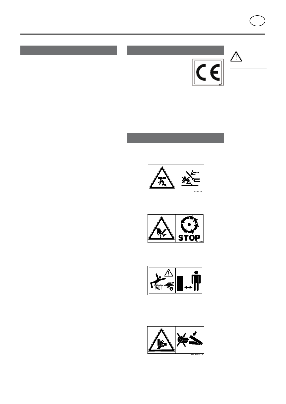
The CE sign, which is affixed by the
manufacturer, indicates outwardly
that this machine conforms to the
engineering guideline regulations and
the other relevant EU guidelines.
By signing the EU Declaration of Conformity, the
manufacturer declares that the machine being brought
into service complies with all relevant safety and health
requirements.
Stay clear of swinging area of implements
Wait until all machine components have completely
stopped before touching them.
Do not enter rotor area while driving motor is running.
Never reach into the crushing danger area as long as
parts may move.
0800_GB-INHALT_2041
- 4 -

HITCHING
TD34/90/4
5
4
GB
Hitching of machines with three point linkage
Safety hints:
see supplement-A1 points 7.), 8a. - 8h.)
- Pinning the machine to the three point linkage.
- Fix the hydraulic lower link (4) in such a way that the
machine cannot swing out sideways. Push in the
support foot (5) and secure.
Drive shaft adaption
"Shorten the drive shaft" see Supplement-B .
Locking the headstock during use on
roads and when lowering
For transport the headstock (SB) must be locked using
a lock nut.
A = working position
B = transport position
Hydraulic hoses and electrical cables
Note: Overlengthed hydraulic hoses and electrical cables
are fitted to the machine. This enables the machine to
be coupled to various tractors
• Roll hydraulic lines and electrical cables together
appropriately and secure with cable binders (K).
Rotating rotor must not damage hydraulic
•
hoses and electrical cables.
here must always be sufficient distance to
T
the rotating parts even when cornering.
Observe lengths "L1 and L2"!
•
Important!
Only reposition the
lock pin when the
machine is in the
raised position.
Connecting hydraulic system to the tractor
For reasons of accident prevention the
p.t.o. must be switched off and the rotors
must come to a stand still before raising the
side rotors.
Release rope (Only lifting
is hydraulic)
-
Run rope (S) into tractor
cabin.
0800_GB-Anbau_2041
- 5 -

HITCHING
FETT
GB
Lowering the rotary tedder
Always park implement stabily!
- secure against rolling and tipping over.
• The implement can be parked while in the transport or
working position.
Secure bolts in position B on the headstock (SB).
-
Parking in the open
• When parking for longer periods in the open, clean
plunger rods and then coat with grease.
Important!
- The runner wheels on the swivelled up rotors are to be
turned vertically.
Doing this will prevent rain water from penetrating the
wheel bearings.
Important!
reposition bolts when the machine is
Only
in the raised position.
Lower the machine with the tractor hydraulic system
and place on support foot.
Pull off drive shaft and rest on support.
-
Do not rest drive shaft on safety chain (H)!
- Remove hydraulic cables.
- Unhitch machine from tractor.
Winter storage
The runner wheels should be disengaged when garaging
the implement.
0800_GB-Anbau_2041
- 6 -
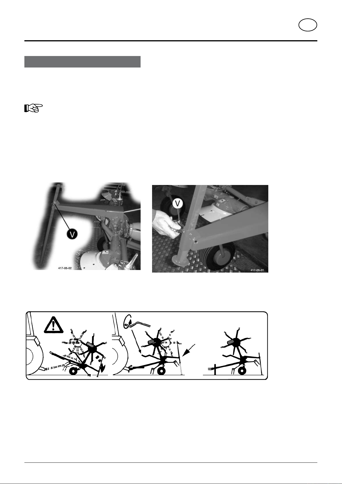
Lowering the machine (Danger of tipping!)
- Only park implement with side rotors swivelled up
(Danger of tipping).
If a rotory tedder is to be parked with the
side rotors swivelled up, the following must
be observed, especially with the draw-bar
machine:
(for HIT 470, HIT 540)
Before uncoupling
- Fold front support stand down and secure
- Pull rear support stand out and down and secure with
pin (V)
Note!
When in operation the support stand must be placed
in the upper position and secured with pin (V).
HITCHING
GB
Use both support stands (otherwise danger of
tipping).
Then uncouple the implement from the tractor.
-
0800_GB-Anbau_2041
- 7 -
ADJUSTMENTS BEFORE OPERATION
TD16/96/1
80
S
1
S
2
80
TD 16/96/2
R
GB
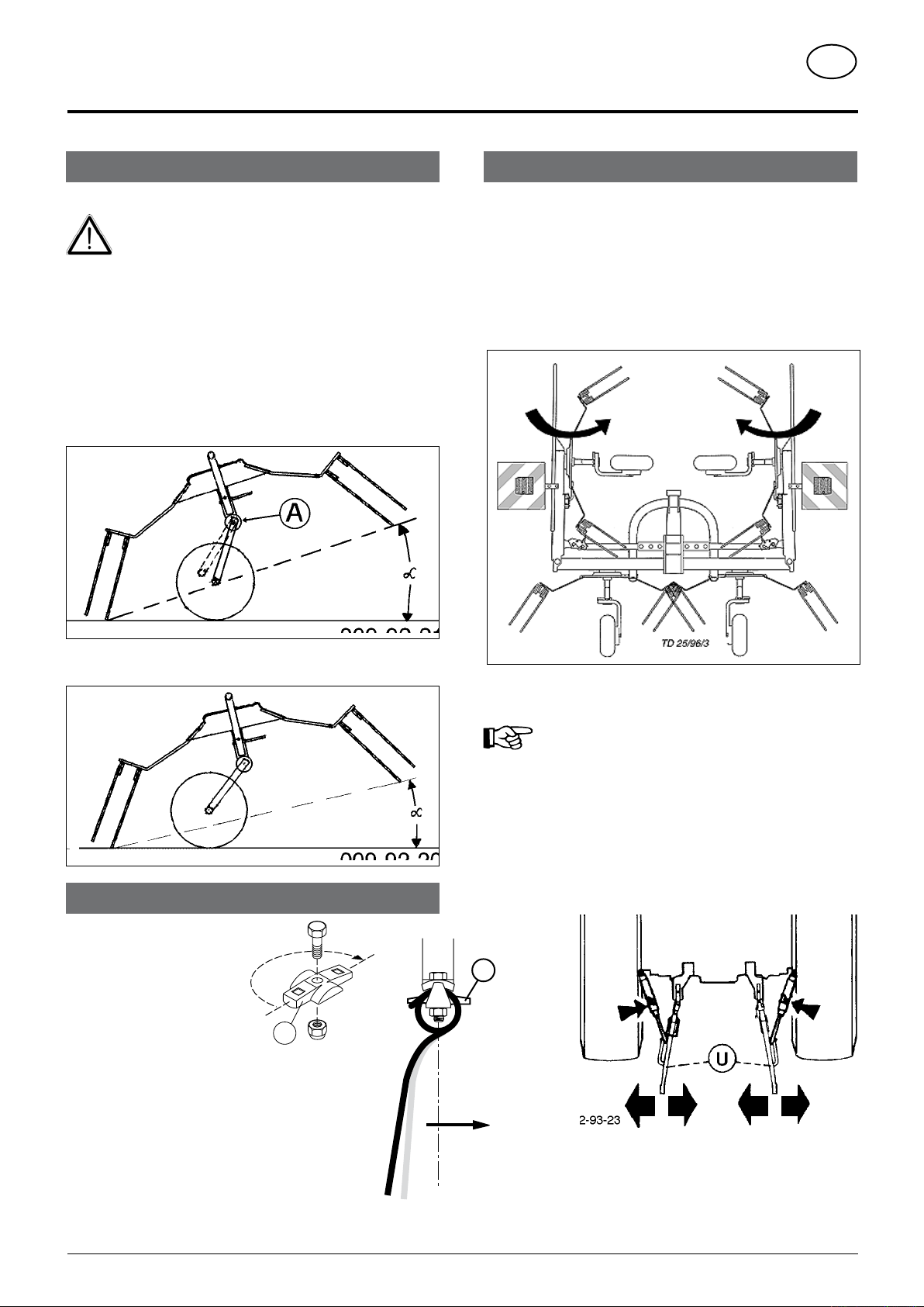
Adjustment of rotor inclination
Safety points
• Turn engine off when adjustment, service and repair
work is to be done.
• Do not work under the machine without safe
support.
Implement with slewing headstock "N"
The cog enables the darrier axles to be adjusted within a swivel
range of 10°.
1 setting = 1° alteration to rotor inclination
A lot of fodder = greater angle
Driving on public roads:
• Observe the official regulations of your country.
• Travelling on open roads may only be carried out as described in
chapter "Transport position".
Total implement width in the working position: more than 3 m
Total implement widht in the transport position: see Techn.
Data
• Always swing the outer rotors in before transporting.
Not much fodder = smaller angle
Tine adjustment
Tine position can be altered
by turning the tine carrier
(80).
• Position "S1"
Stand a rd po s i t ion (ex
factory)
• Position "S2"
For use under difficult conditions, e. g. with very
dense, awkward forage. This tine position increases
the strewing action.
• Direction of rotation "R"
Be aware of this when installing tines.
Only in this position is the maximum permissable transport width
not exceeded.
No-one can be injured by the rotor tines in this
position.
Hydraulic lower link
- Fix the hydraulic lower link (U) in such a way that the machine
cannot swing out sideways.
9500-GB VOREINSTELLUNGEN (204)
- 8 -

TRANSPORTPOSITION
G
C
TD 40/93/3
10
TD26/93/36
G
C
TD 40/93/2
WORKINGPOSITION
GB
Conversion from working to transport position
Safety Precaution!
Changing from working position to transport position
is only to be carried out on even, firm ground.
• For safety reasons, turn off drive shaft and wait for rotor to stop
completely.
• Make sure that swivel area is free and that nobody is standing in
the danger area.
Hydraulic raising (Variation)
- The outer rotors are raised into the transport position by actualing
the control valve (ST).
The locking hooks engage automatically.
Swivelling the outer rotors
- Hold the tubular handle in one hand and release the bolts (position
C) with the other.
- When swivelling do not release the tubular handle until the bolts
are locked again (position G).
Attention !
- Check whether the locking hooks (10) are locked into
position correctly.
Manual raising (standard fitting withe the HIT 47)
- Hold the tubular handle (9) with your hand and during raising
swivel the outer rotor into
the transport position.
The locking hooks engage
automatically.
Attention!
- Check whether the
locking hooks (10) are
locked into position
correctly.
- Using the tractor's lifting
gear, lower the implement far enough so that it stands on the
ground on both centre running wheels.
- Swivel the outer rotors inward to the transport position.
Conversion from transport to workingposition
Safety Precaution!
Changing from working position to transport position
is only to be carried out on even, firm ground.
Make sure that swivel area is free and that nobody
is standing in the danger area.
- Turn the rotors outward.
See "Swivelling the Outer Rotors".
- Release mechanical locks (10).
With hydraulic raising: move the control
valve (ST) briefly to the "raise" position
simultaneously pulling on the rope
(S).
Doing this releases the mechanical
locks (10).
- Lower outer rotors to the working
position.
9500-GB TRANSPORTSTELLUNG (204)
- 9 -
 Loading...