

Pottinger CAT 270 PLUS Operating Instructions Manual

Drum Mower
CAT 270
plus
(Type PTM 338 : + . . 01001)
GB
Operating instructions
Nr. 99 338.GB.80A.0
Ihre / Your / Votre • Masch.Nr. • Fgst.Ident.Nr.

ALLG./BA SEITE 2 / 9300-GB
Important information concerning Product Liability.
According to the laws governing product liability, the manufacturer and dealer are
obliged to hand the operating manual to the customer at the time of sale, and to
instruct them in the recommended operating, safety, and maintenance regulations.
Confirmation is necessary to prove that the machine and operating
manual have been handed over accordingly.
For this purpose, document A is to be signed and sent to Pöttinger,
document B remains with the dealer supplying the machine, and the
customer receives document C.
In accordance with the laws of product liability, every farmer is an entrepreneur.
According to the laws of product liability, property damage is damage caused by a
machine and not to it. An excess of Euro 500 is provided for such a liabilioty.
In accordance with the laws of product liability, entrepreneurial property damages
are excluded from the liability.
Attention! Should the customer resell the machine at a later date, the operating
manual must be given to the new owner who must then be instructed in the
recommended regulations referred to herein.
GB
Dear Farmer
You have just made an excellent choice. Naturally we
are very happy and wish to congratulate you for
having chosen Pöttinger. As your agricultural partner,
we offer you quality and efficiency combined with
reliable servicing.
In order to assess the spare-parts demand for our
agricultural machines and to take these demands
into consideration when developing new machines,
we would ask you to provide us with some details.
Furthermore, we will also be able to inform you of new
developments.

- 3 -
(338) INHALT 9800-GB
CONTENTS
GB
Observe safety hints in supplement-A
Table of contents
Meaning of warning signs ...................................................................4
Lowering the frame .............................................................................5
Winter storage.....................................................................................5
Raising the frame ................................................................................5
Attaching implement to tractor ............................................................6
Adjusting lower links............................................................................7
Important recommendation! ................................................................ 7
Fitting drive shaft.................................................................................7
Conversion from Working to Transport Position .................................. 8
Transport Position 1 ............................................................................8
Transport Position 2 ............................................................................8
Reducing the Total Height in the Transport Position............................8
Transport Position 3 ............................................................................ 9
Reducing the Total Height in the Transport Position............................9
Conversion from Transport to Working Position ..................................9
Lowering the Machine.........................................................................9
Parking in the open .............................................................................9
Take care when turning on slopes! ...................................................10
Safety hints .......................................................................................11
Cutting height adjustment .................................................................11
Cutting height adjustment .................................................................11
Operation ..........................................................................................12
Adjustment: .......................................................................................12
Adjustment of both swath makers(8i .................................................13
Adjustment of swath width(8i ............................................................13
Collision safety de vice:......................................................................14
Function of collision safety device:....................................................14
Adjustment: ....................................................................................... 14
Safety points .....................................................................................15
General maintenance hints ...............................................................15
Repair Instructions ............................................................................ 15
Cleaning of machine parts ................................................................15
Parking in the open ...........................................................................15
Winter storage...................................................................................15
Drive shafts .......................................................................................15
Hydraulic unit ....................................................................................15
Check initial spring tension. ..............................................................16
Cutters ..............................................................................................16
Changing the cutters .........................................................................16
Checking the mowing blade suspension...........................................16
Mower disc ........................................................................................16
Danger of accident if wearing parts are worn ...................................17
Danger of accident if: ........................................................................ 17
PUTTING AWAY FOR THE WINTER................................................18
Raising the frame ..............................................................................18
Technical data ...................................................................................19
The defined use of the mower unit....................................................19
Position of Vehicle Identification Plate...............................................19
Correct loading..................................................................................19
Supplement .......................................................................................20
Recommendations for work safety....................................................21
DRIVESHAFT ...................................................................................22
LUBRICATION CHART .....................................................................25
Attachment variations .......................................................................26
Important! Additional Information ......................................................27
Combination of tractor and mounted implement ...............................27

- 4 -
(361) AZB 9700-GB
GB
WARNING SIGNS
CE sign
The CE sign, which is affixed by the manufacturer, indicates outwardly that this machine conforms
to the engineering guideline regulations and the other relevant EU guidelines.
EU Declaration of Conformity (see supplement)
By signing the EU Declaration of Conformity, the manufacturer declares that the machine being
brought into service complies with all relevant safety and health requirements.
Meaning of warning signs
Danger - flying objects; keep safe distance from the
machine as long as the engine is running.
Wait until all machine components have stopped
completely before touching them.
Stay clear of mower knife area as long as tractor
engine is running with PTO connected.
Shut off engine and remove key before performing
maintenance or repair work.
Stay clear of swinging area of implements
Close both side protective coverings before engaging
p.t.o..
Never reach into the crushing danger area as long
as parts may move.
Recommendations for work safety
All points referring to satety in this manual
are indicated by this sign.
495.151
495.167
(354) ANBAU / 9600-GB
ATTACHMENT
GB
- 5 -
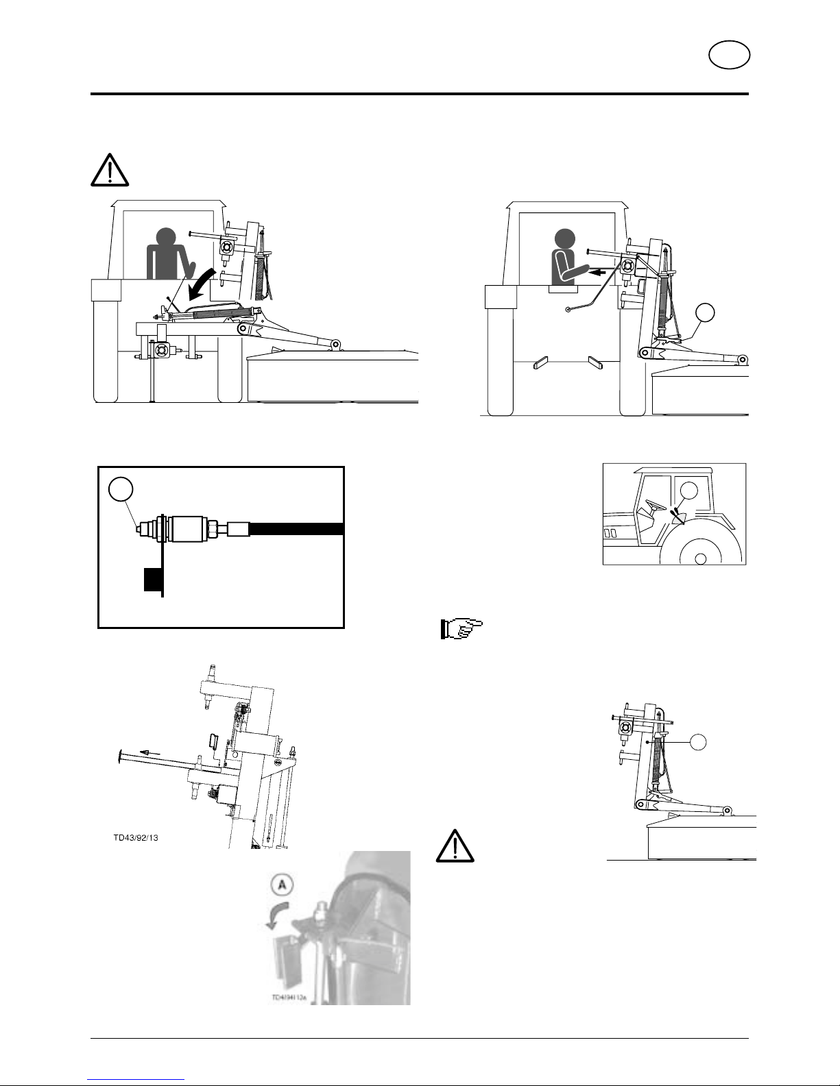
Lowering the frame
Safety hints:
see supplement-A1 points 8a. - 8h.)
- Connect hydraulic snap coupling (60) for swivel cylinder.
- Pull out jack stand and secure
with cotter pin.
- Open U-shaped flap
(positionA).
- Release hook (16) by means of rope.
- By controlling the tractor
servo-valve (ST), lower the
frame slowly.
60
TD 79/90/30
TD 79/90/31a
H
Winter storage
A rusty plunger rod can damage cylinder's sealing
elements.
At season's end
- clean plunger rod and all other shiny parts, then grease them
- park implement with
attachment frame (H) raised,
which will protect plunger rod
from rust
- pay attention to the hints in
chapter "MAINTENANCE"
Raising the frame
Safety hints:
see supplement-A1
Pkt.8a. - 8h.)
- Do not attach implement to tractor's lifting gear.
- Connect hydraulic snap coupling (60) for swivel cylinder.
- Release hook (16) by means of rope.
- Control the tractor servo-valve (ST), raise the frame slowly.
TD 79/90/28
16
ST

(338) TRAKANBAU 9800-GB
A TT ACHING T O TRACT OR
GB
- 6 -
TD25/90/21
15
TD25/90/8
16
Attaching implement to tractor
Safety hints:
see supplement-A1 points 7.), 8a. - 8h.)
- The U-shaped flap (if available) should be
swivelled up (A).
In this position the relieving spring is not so
strongly tensioned which enables the mower's
attaching frame to remain horizontal.
- Attach mower so that the edge of the tractor-side drum is just outside the righthand tractor tyre!
- See also chapter "Side-located attachment", supplement-D
- Adjust lower link bolt (1) on frame accordingly.
- Bring frame into horizontal position by adjusting linkage arm spindle (15).
- By turning upper link spindle (16) the cutting height is adjusted .
(338) TRAKANBAU 9800-GB
A TT ACHING T O TRACT OR
GB
- 7 -
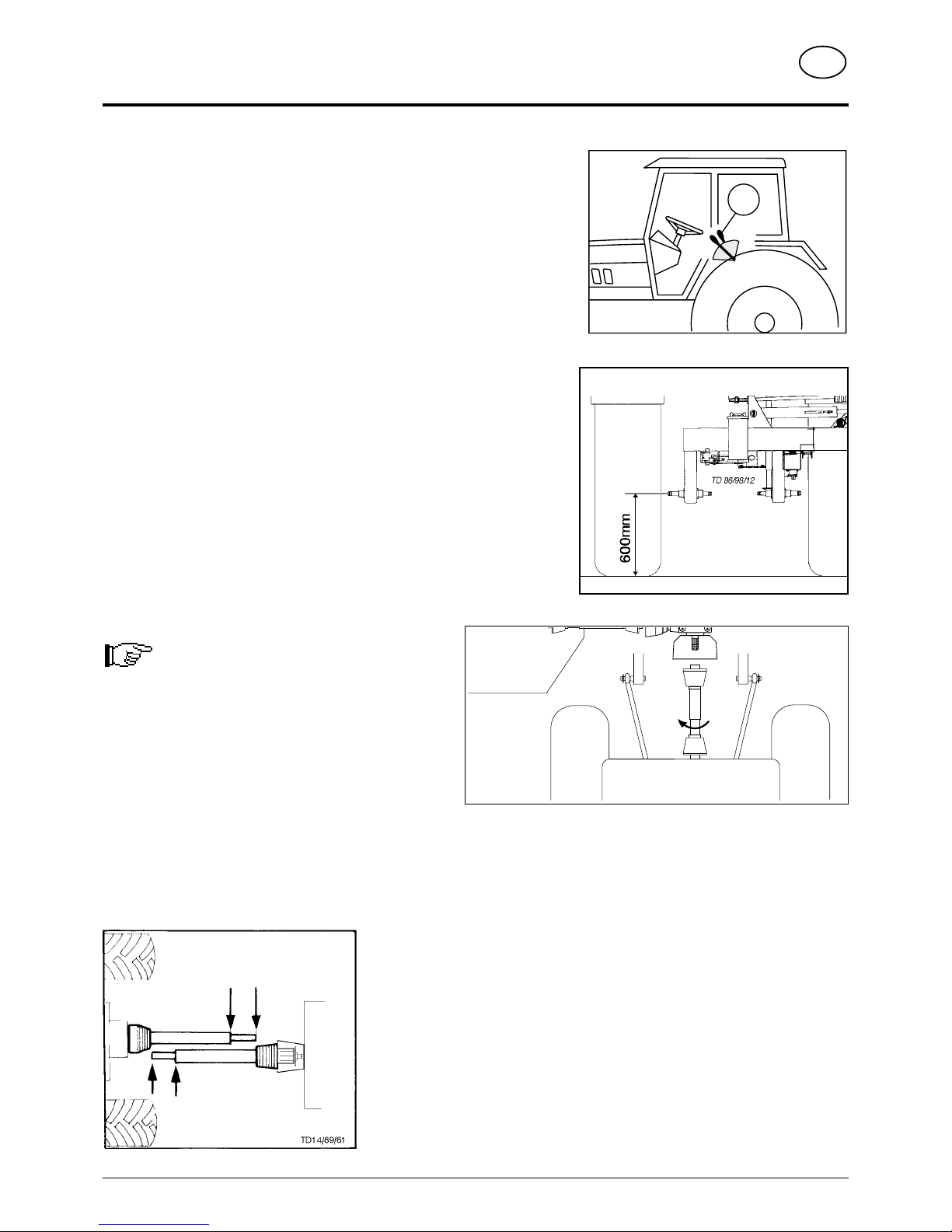
Adjusting lower links
- Adjust tractor's hydraulics (ST) using bottom stop.
Lower links approx. 600 mm.
This height allows optimal evenness when working on uneven ground and need
not be changed for swinging cutter bar up.
- Connect hydraulic snap coupling for swivel cylinder.
Important recommendation!
A transfer, which is located near the gear, advises
which p.t.o. speed your mower unit is equipped for.
Standard: Gear for power take-off 1000 rpm.
Order number: spare part book
Fitting drive shaft
- Before operating for the first time, drive shaft is to be checked and adapted if
necessary. See alse chapter "Drive Shaft" in supplement B.
ST
1000 rpm
540 rpm
TD 18/96/2
(358) TRANSPORTSTELLUNG 9500-GB
TRANSPORT AND WORKING POSITION
- 8 -
GB
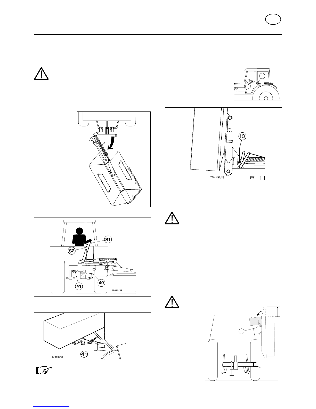
Transport Position 2
• Mower bar only swivelled up at the side.
- Pull on rope (S2) and
simultaneously actuate servovalve (ST).
- Gradually move cutter bar into
vertical position and release
rope(S2).
- Secure cutter bar with hook (13).
- Before driving on roads always check correct locking!
Attention!
Never let mowing mechanism run with the mower
raised.
- Connect lighting and raise implement for transport .
- Before leaving the tractor lower cutter bar to ground!
Reducing the Total Height in the Transport
Position
Before converting to transport position
• The external guard plate (10) can be swivelled in to reduce
the total height (- 30 cm) when in the transport position.
For safety reasons the mower disks must be at a
complete standstill before swivelling the guard plate.
Conversion from Working to Transport
Position
Safety Precaution!
see supplement-A1 points 7.), 8c. - 8h.)
Changing from working position to transport position
is only to be carried out on even, firm ground.
• The mower bar can be swivelled into 3 different positions for
transportation.
Transport Position 1
• Mower bar
swivelled back.
- Lower cutter bar to
ground.
- Release hook (40)
by pulling on the
rope (S1) and move
forwards with the
tractor.
In doing so, the
cutter bar swivels
back so far until the hook(41) is locked into position.
- Raise the implement using the tractor's lifting gear.
Note: Only short runs at low speed may be carried
out in this position.
TD47/93/5
30 cm
10
TD43/92/20
ST
(358) TRANSPORTSTELLUNG 9500-GB
TRANSPORT AND WORKING POSITION
- 9 -
GB
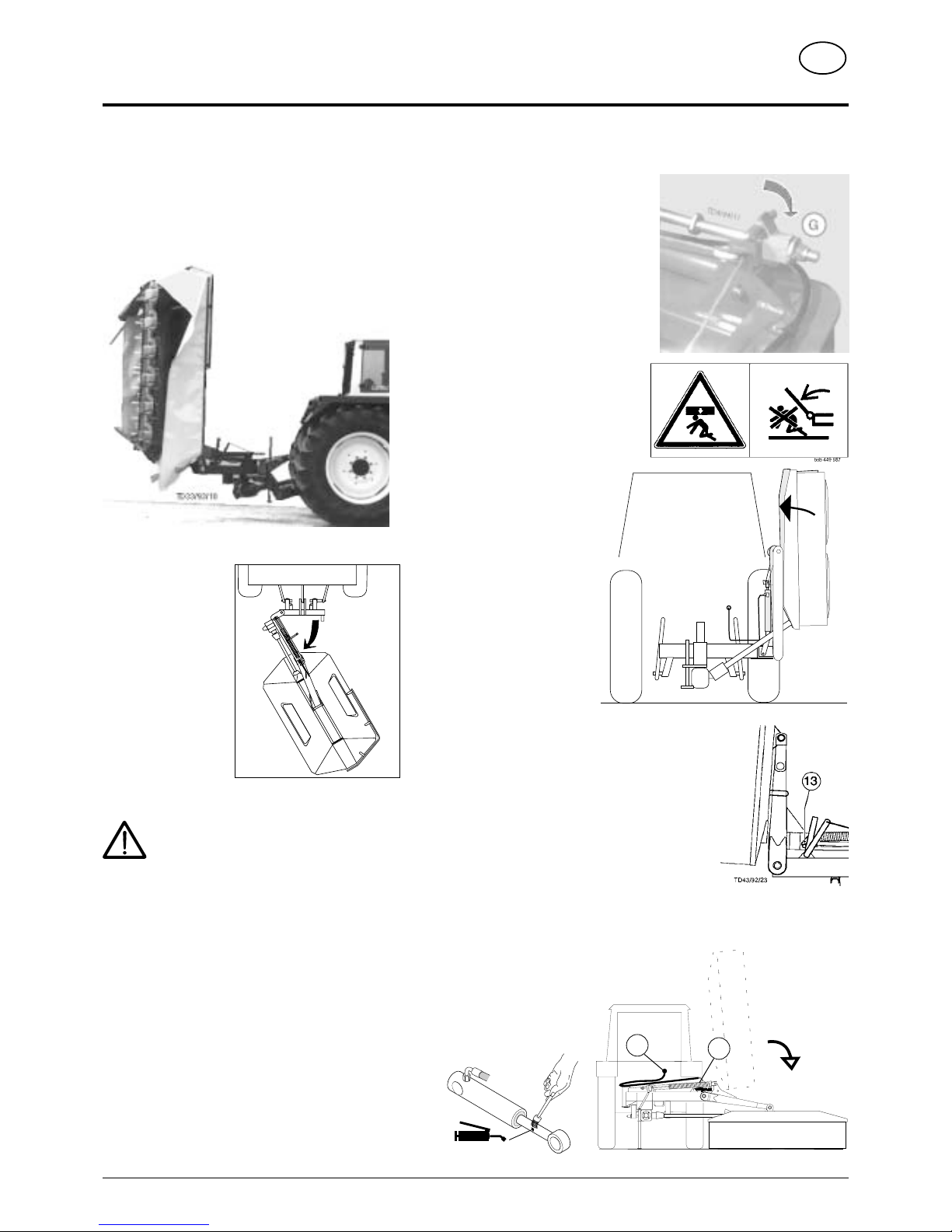
Conversion from Transport to Working Position
- Swivel U-shaped flap into position
"G".
When cutting bar is lowered the
relieving spring is somewhat more
tensioned which enables the bar to
rest on the ground with less weight.
Swinging cutter bar down
- Make sure that swivel area is free
and that nobody is standing in the
danger area.
- Gently raise cutter bar with
swivel cylinder so that hook
(13) can be released.
- Release hook (13) by pulling on the rope (S2).
- Lower cutter bar hydraulically.
Lowering the Machine
- Before disconnecting hydraulic hose (26) extend cylinder (27) completely,
so that no residual pressure interferes with connecting up later.
Parking in the open
When parking for longer periods in the
open, clean plunger rods and then coat with
grease.
Transport Position 3
• Mower bar swivelled back and then up.
1. Swivel mower bar back as described in "Transport
Position 1".
2. Move mower bar
into vertical position
as described in
"Transport Position
2".
- Secure cutter bar
with hook (13).
3. Before driving on
roads always check
correct locking!
Attention!
Never let mowing mechanism run with
the mower raised.
- Connect lighting and raise implement
for transport.
- Before leaving the tractor lower cutter bar to
ground!
Reducing the Total Height in the
Transport Position
In this position the external guard plate can also
be swivelled in (see previous page).
TD 20/91/2
PÖTTINGER
27
26
FETT
TD49/93/2
TD43/92/20
TD25/90/26A
(358) 9500-GB HANGFAHRT
- 10 -
WORKING ON SLOPES
GB
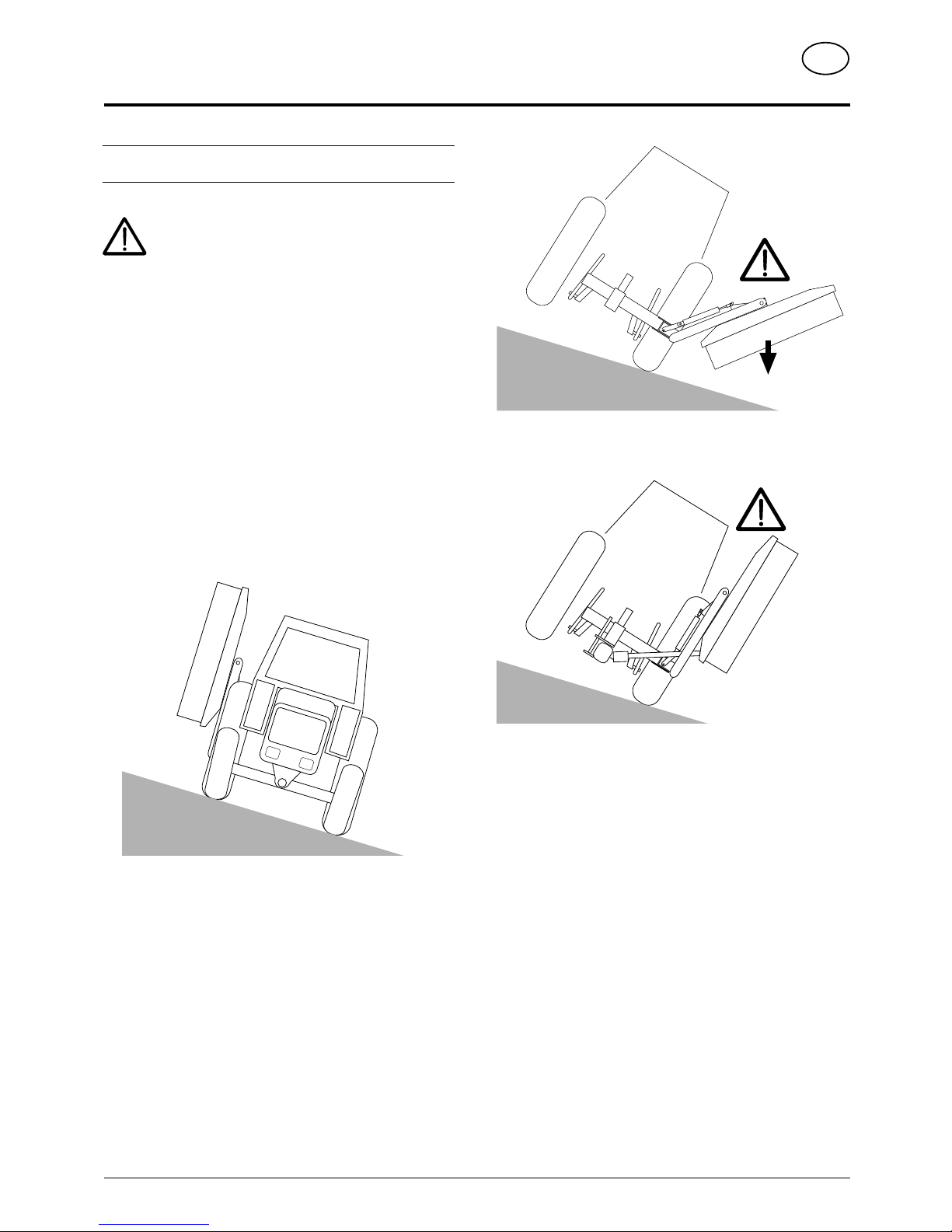
Take care when turning on slopes!
The tractor's travelling characteristics are influenced by the
weight (G) of the mower unit. This can lead to dangerous
situations, especially on slopes.
Danger of tipping occurs
- when the mower unit is facing downhill and in a raised position,
- when travelling in a left-hand curve with the mower unit raised,
- when travelling in a left-hand curve in the transport position (mower
unit completely raised).
Safety advice
• Reduce speed in left-hand curves accordingly.
• Travel so that the raised mower unit is facing uphill.
• It is better to travel in reverse on a slope than to carry out a risky
turning manoeuvre.
TD15/95/3
G
TD15/95/2
TD15/95/4
 Loading...