

Page 1

pottery barn kids
THOMAS STORAGE DESK HUTCH
PRE-ASSEMBLY:
• Please read all instruction before beginning assembly. The illustrations provided allow for easier
assembly when used in conjunction with the assembly instructions.
• Remove all parts and hardware from box and lay out on a carpeted or scratch-free work surface, as this
will avoid damaging any parts during assembly. The shippin g box provides and ideal wo rk surface. Do
not dispose of any contents until assembly is completed to avoid accident ally discarding sm all p art s or
hardware.
• For your safety and ease, two adult assembly is recommended.
• Save all packing materials until assembly is complete to avoid accidentally discar ding smaller parts or
hardware.
• Use the parts and hardware lists to identify and sep arate each of the pieces included prior to starting
assembly.
• Note: DO not fully tighten all bolts until all parts are in place. Failure to follow these instructions may
cause the bolts to misalign during assembly.
• If using power tools to aid in assembly please use caution. Power tools can damage hardware of split
wood.
PARTS INCLUDED:
(A) Top panel – 1pc
(B) Right Side panel – 1pc
(C) Left Side panel – 1pc
(D) Divider – 2pcs
(E) Shelf – 1pc
(F) Back upper panel – 1pc
(G) Back lower panel – 1pc
TOOLS REQUIRED:
Phillips Head Screwdriver (not included)
HARDWARE ENCLOSED:
(H) Allen Key – 1pc
Page 1/5
Page 2
(I) Short bolt 1/4”x32x15mm – 6pcs
(J) Phillips head screws 8x32mm – 2pcs
(K) Phillips head screws 7x20mm – 20pcs
(L) Metal plate 70x40mm – 2pcs
(M) Bracket 48x21x10mm – 2pcs
(N) Long screw 6x32mm – 2pcs
(O) Short screw 6x19mm – 2pcs
(P) Nylon strap 300x12x8mm – 1pc
ASSEMBLY INSTRUCTIONS:
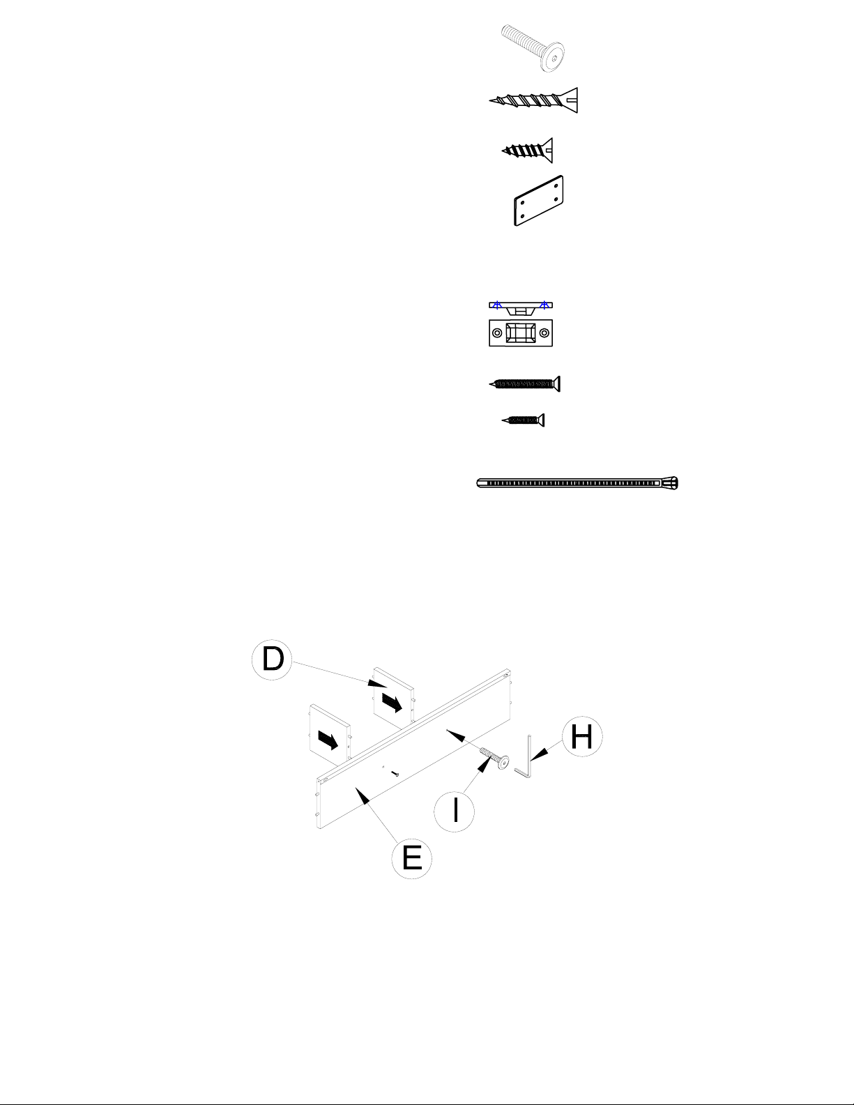
1. Att ach the Dividers (D) to the Shelf (E) by inserting the pre-attached wooden dowels on the Dividers (D)
into the pre-drilled holes on the Shelf (E). Attach using Short Bolts 1/4”x32x15mm (I) and Allen Key (H), as
shown. (Fig. 1)
(Fig. 1)
Page 2/5
Page 3

2. Attach the Shelf (E) with the Dividers (D) to the Right Side p an el (B) and Lef t Side Panel (C) by inse rting the
pre-attached wooden dowels of the Shelf (E) into the pre-drilled holes on the Right and Lef t Side Panels (B & C).
At same time, attach the Back Upper Panel (F) by sliding into the grooves of the Right and Left Side Panels (B
& C). Attach using the Phillips Head Screws 8x32mm (J) from the underside of the Shelf (E), as shown below.
(Fig. 2).
(Fig. 2)
3. Place the Top Panel (A) on a soft, scratch-free surface, as below figure shown. Insert previously
assembled piece into the Top Panel (A) and attach to the Right Side Panel (B) and Left Side Panel (C) by
inserting the Short Bolts ¼”x32x15mm (I) through the pre-drilled holes on the underside of the Top Panel (A)
and into the pre-drilled holes of the Right and Left Side Panels (B & C), as shown. Tighten using the Allen
Key (H), as shown. (Fig. 3).
(Fig. 3)
Page 3/5
Page 4

4. Holding the Back Upper Panel (F) in place, turn the assembly upright. Place the Back Lower Panel (G) over
the pre-drilled holes of the assembled piece, as shown below . The Back Lower Panel (G) will cover the lower
edge of the Back Upper Panel (F). Attach the Back Lower Panel (G), using the Phillips Head Screws 7x20mm
(K). (Fig. 4)
(Fig. 4)
5. Carefully place the desk hutch on the desk in upright position on the desk. Attach the two by placing the
Metal Plates (L) over the pilot holes on the back edge of the desk and hutch. Fasten with the small Phillips
Head Screws 7x20mm (K) and tighten with a Philips head screwdriver (not included). (Fig. 5)
(Fig. 5)
CARE INSTRUCTIONS:
• Dust often using a clean, soft, dry lint-free cloth.
• Blot spills immediately, and wipe with a clean, damp, cloth.
• We do not recommend the use of chemical cleanse rs, abrasives, or furniture polish on our lacquered
finish.
stores | catalog | www.potterybarnkids.com
Thank you for your purchase
USA 1.800.290.8181
Page 4/5
Page 5

FURNITURE TIPPING RESTRAINT
Young children may be injured by tipping furniture. The use of a tipping restraint is highly recommended.
When properly installed, this restraint could provide protection against the un expected tipping of furniture due to
small tremors, bumping or climbing. We recommend mounting this restraint to a wall stud.
WARNING: This product is only a deterrent. It is not a substitute for proper adult supervision.
Hardware Included (also described on page t wo):
L - Brackets (x 2)
M - Long screws (x 2)
N - Short screws (x 2)
O - Nylon strap (x 1)
INSTALLATION INSTRUCTIONS:
1. Determine the final resting position of the
furniture piece. Locate a stud in the wall behind
that furniture piece. Mark the location on the
wall approximately 1” below the top of the
furniture piece. Mark and drill pilot hole into the
center of the stud with a 3/32” drill bit. Attach a
bracket to the stud with the long screws
provided.
2. On the back of the furniture, a bracket will need
to be attached to the furniture frame at the top.
To do this, temporarily move the furniture into
its final position and mark the location of the
wall bracket on the furniture frame.
3. Move the furniture away from the wall and
place a bracket on the mark. Mark and drill
holes for screws with a 3/32” drill bit. Attach
the bracket to the furniture with the short
screws provided.
4. Check to be sure the wall bracket is firmly
screwed into wall and the furniture bracket is
firmly attached to the frame.
5. Move the piece of furniture into its final
position so that the wall bracket and furniture
bracket are in alignment.
6. Thread the strap through brackets and
tighten until snug. Do not over- tighten.
7. Check to make sure the brackets are firmly
installed and the strap is secure.
Page 5/5
 Loading...