

Page 1
pottery barn kids
PUZZLE WALL L-SHAPED CUBBY
PRE-ASSEMBLY:
•
Read all instructions before beginning assembly. The illustrations provided allow for easier assembly when used in
conjunction with the assembly instructions.
•
For your safety and ease, assembly by two adults is recommended.
•
Remove all part and hardware from the box and lay out on a clean, carpeted, or scratch- free work surface. Use
care as some parts or hardware may have sha rp points or edges.
•
Do not dispose of any contents until assembly is completed to avoid accidentally discarding small parts and hardware.
•
Use the parts and hardware lists to identify and separate each of the pieces included.
•
Note: Do not fully tighten all bolts until all parts are in place. Failure to follow these instructions may cause the bolts
misalign during assembly.
•
The use of power tools for assembly is not recommended. Power tools can damage hardware or split wood.
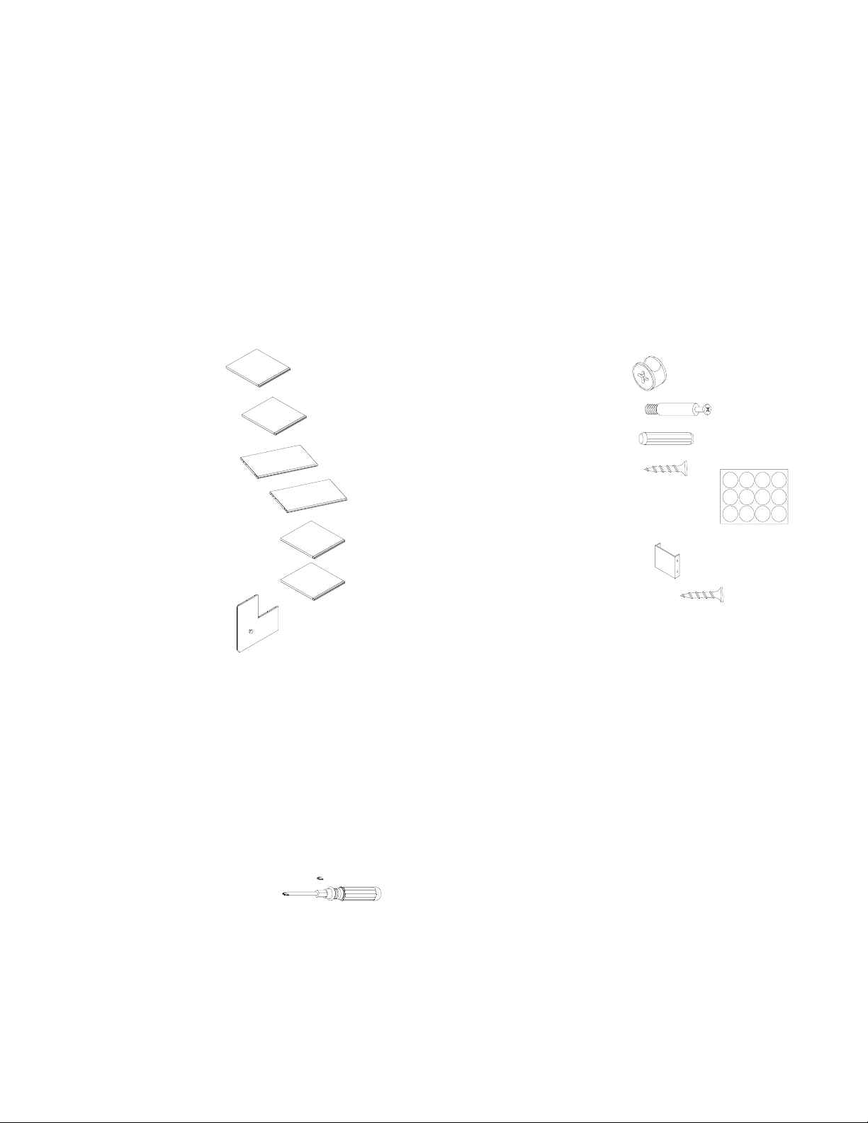
P AR T S INCLUDED:
(A) Top Panel (1)
(B) Middle Panel (1)
(C) Bottom Panel (1)
(D) Long Side Panel (1)
(E) Medium Side Panel (1)
(EE) Short Side Panel (1)
(F) Back Panel (1)
P ARTS AND HARDWARE REQUIRED (Packaged Separately):
Double-Wide and/or Triple-Wide Bases
Base Screws:
o Double Wide Bases include:
(8) Screws- 8 X 1”
o Triple-Wide Bases include:
(12) Screws- 8 X 1”
CUBBY HARDWARE ENCLOSED
(G) CAM LOCK (12)
(H) CAM LOCK BOLT (12)
(I) WOOD DOWEL (12)
(J) LONG SCREW- 8X1” (18)
(K) ESPRES SO STICKER-22mm (12)
CONNECTING HARDWARE ENCLOSED:
(a): U PLATE(2)
(b) SHORT SCREW- 8X3/4” (8)
TOOLS REQUIRED: (not included)
Phillips head screwdriver
Page 1/5
Page 2
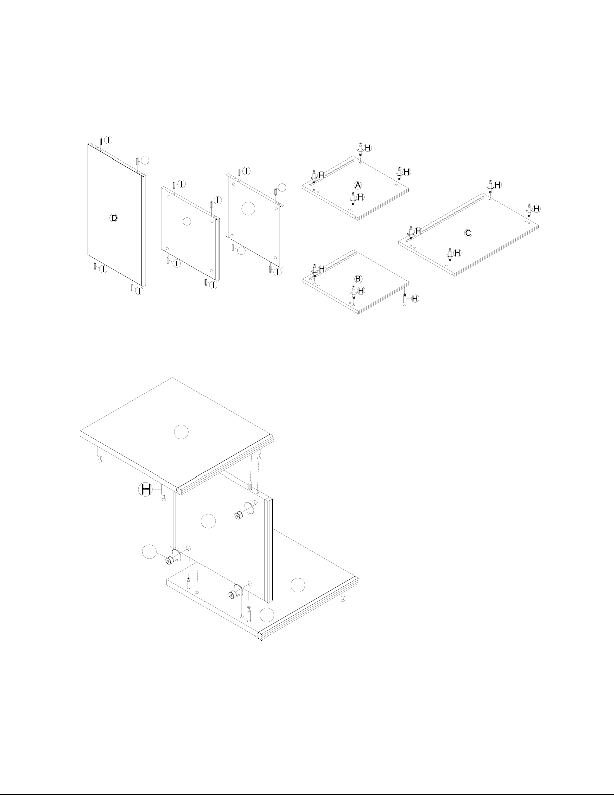
ASSEMBL Y INSTRUCTIONS:
1. Insert (4) Wood Dowels (I) into the pre-drilled holes on each Side Panel (D) (E) and (EE) (Figure 1). The n, fasten (4 )
Cam Lock Bolts (H) into the predrilled holes in each Top Panel (A), Middle Panel (B) and B ot tom panel(C), using
the Phillips Head Screwdriver as shown in Figure 2. Do not over tighten the Cam Lock Bolts or the Cam Locks
will not properly engage in Steps 2, 3 and 4.
E
E
E
2. Attach the Medium Side Panel (E) to the Top Panel (A) and Middle panel (B), as shown. Insert the Cam Locks (G)
into the (4) corresponding pre-drilled holes, then fasten using the Phillips Screwdriver (Figure 3).
Figure 1. Figure 2
A
E
G
B
H
.
Figure 3
Page 2/5
.
Page 3
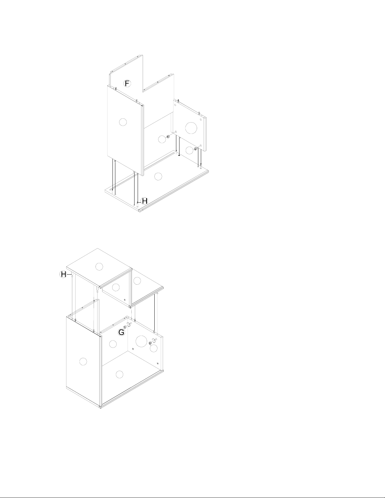
3. Attach the Long Side P anel (D ) and Sh ort S i de Panel ( E E ) t o the bott om panel (C), as shown. I n s ert the back panel (F)
through the U-groove on the side panel. Insert Cam Lock (G) into each of the (4) corresponding holes
on the Side Panels (D/EE) and tighten using Phillips Head Screwdriver. (Figure 4).
D
E
E
G
G
C
4. Place the Step 2 Assembly onto the Step 3 Assembly, as shown. Insert Cam Lock (G) into each of the corresponding
holes on the Side Panels (D/EE) and tighten using the Phillips Screwdriver. (Figure 5).
Figure 4
A
B
E
E
F
E
G
D
C
Figure 5
5. Use Phillips screwdriver to tighten all the Cam Locksusing the (12) Espresso Sticker (K) to cover the Cam Locks.
Page 3/5
Page 4
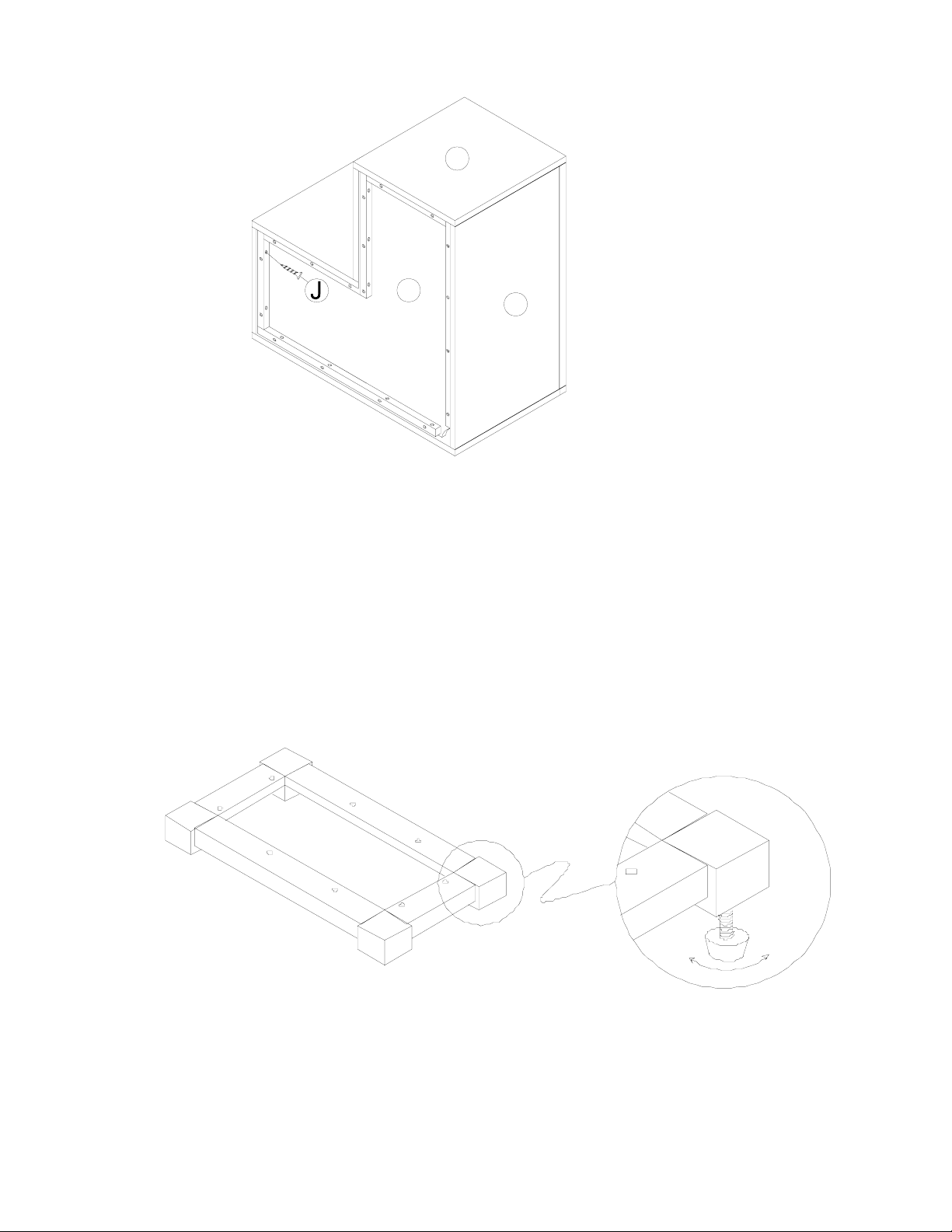
6. Secure the Back Panel (F) with (18)
Long
Screws (J), using the Phillips Head Screwdriver (not included) (Figure 6).
A
F
D
BACK VIEW
Figure 6
COMPLETING THE ASSEMBL Y:
Your Puzzle Wall System contains a set of individual components that can be attached together in a variety
of combinations to suit your own space. To assemble the set together, please follow these steps:
1.
Choose your preferred layout by arranging the Puzzle Wall Cubbies together as desired, atop the Bases
(packaged separately). If needed, loosen or tighten the adjustable levers on the underside of the Bases to
ensure
that your system will sit firmly on the ground.
Left
Page 4/5
Rig ht
Page 5

2.
Turn pieces upside down and fasten the Bases to the Bottom Cubbies using the 8 X 1” screws, as shown
below.
BASE
Fasten from the underside of
the Base through the underside
the Cubby
of
3.
Attach the individual Puzzle Components together by fastening the U Plates (a) with (4) Screws (b) each along
the back edges, as shown, using the Phillips Head Screwdriver (not included).
BACK VIEW
As a safety precaution, please follow the instructions enclosed to secure the Puzzle Wall Unit to the wall using
the
tipping-restraint kit included.
CARE INSTRUCTIONS:
a
Dust often using a clean, soft, dry lint-free cloth.
a
Blot spills immediately, and wipe with clean, damp, cloth
a
We do not recommend the use of chemical cleansers, abrasives, or furniture polish on our lacquered finish.
Thank you for your purchase
Stores l catalog l www.potterybarnkids.com
USA 1.800.290.8181
Page 5/5
 Loading...