

Page 1
PI 4100
Medium-Wave Field Strength Meter
User’s Guide
Page 2

The following items are included with the original packing:
The PI 4100
PI 4100 User’s Guide
CD including PI 4100 Data Downloader software, 4100 Data Report
Template1software, and the PI4100 Field Calibration Data Sheet
Operator’s Quick Reference Guide
Charging power supply and power cord
Charging cable for vehicle use
USB A to B Cable
Battery holder for six AA cells
About the packing material:
Save the box and foam insert for use when returning the PI 4100 for calibration or
repair. See the User's Guide or www.pi-usa.com for return procedures.
Note that the foam inserts will fit exactly into the PELICAN® 1610 CASE for transport
and storage. This case is available from a number of suppliers that can be reached
via the internet.
Page 3

PI 4100 Medium Wave Field Strength Meter
User’s Guide
Operating and Service Instructions
Version E, Universal
15 January 2014
Potomac Instruments inc,
7309 Grove Road, Unit D, Frederick, MD 21704, USA
Page 4

Table of Contents
1. General Description .............................................................................................. 6
1.1 Overview .................................................................................................. 6
1.2 PI 4100 Key Feature ................................................................................ 7
1.3 Specifications ........................................................................................... 8
2. Receipt and Inspection .......................................................................................... 11
2.1 Unpacking ................................................................................................ 11
2.2 Reshipment to factory .............................................................................. 11
2.3 Service and Warranty for Equipment and Accessories ............................ 11
2.4 Factory contact information…………………………………………….. 11
3. Controls,Indicators, and External Ports ............................................................ 12
3.1 Front Panel ................................................................................................ 12
3.2 Primary Display Screen Elements ............................................................ 14
3.3 Rear Panel Signal and Power Ports ........................................................... 15
4. Operation ................................................................................................................ 16
4.1 First-Time Operation ................................................................................ 16
4.2 PI 4100 Operating Procedure Details ....................................................... 18
4.2.1 Setting the operating frequency ................................................ 18
4.2.1.1 Turn-on frequency ……............……………………. 18
4.2.1.2 MENU-Tx select ...………………………………… 18
4.2.1.3 FREQ PRESET ……………………………………. 18
4.2.1.4 FREQ SET ...……………………………………… 18
4.2.1.5 Harmonics …………………………………………. 18
4.2.2 Entering and changing station data for GPS use ....................... 18
4.2.2.1 Enter station data using MENU – Tx add..……….. 19
4.2.2.2 Enter station data using Data Downloader ………… 19
4.2.2.3 Change existing station data: MENU – Tx edit…… 19
4.2.3 Self-calibration, automatic and manual ..................................... 20
4.2.4 Saving Measurements: SAVE and HOLD ................................ 20
4.2.4.1 Starting a save …….……………………………….. 20
4.2.4.2 Completing the save ……………………………….. 21
4.2.4.3 Entering Save screen data before measuring ………. 21
4.2.4.4 The HOLD key …………………………………….. 21
4.2.4.5 View and delete saved data ………………………... 21
4.2.5 Measuring Field Strength .......................................................... 21
4.2.5.1 Field strength units ………………………………… 21
4.2.5.1 Loop antenna orientation …………………………... 21
4.2.5.3 LPF use…………………………………………….. 21
4.2.5.4 DC field strength output …………………………… 22
4.2.5.5 Temperature effects ………………………………... 22
Page 5

4.2.5 Measuring Field Strength, cont’d
4.2.5.6 Measuring pure DRM transmissions ………………. 22
4.2.5.7 Measuring HD Radio all-digital transmissions…… 22
4.2.5.8 Low measuring limit ….……………………………. 22
4.2.5.9 High measuring limit ……………………………….. 22
4.2.5.10 Frequency range for measurements ……………….. 23
4.2.6 Measuring Harmonics ................................................................ 23
4.2.6.1 Measurement conditions ……………………………. 23
4.2.6.2 Measurement procedure …………………………….. 23
4.2.7 Spectrum mode operation .......................................................... 23
4.2.8 Measuring RF voltage: the RF In BNC jack ............................. 24
4.2.9 RF Out BNC jack use.................................................................. 24
4.3 Menu Operation Reference ........................................................................ 25
4.3.1 Menu Navigation………………………………………………. 25
4.3.2 Menu Item Description………………………………………… 25
4.4 Battery Information .................................................................................... 27
4.4.1 Charging the battery ................................................................... 27
4.4.2 Loose-cell battery ....................................................................... 27
4.5 Data storage and retrieval: The PI 4100 Data Downloader program .......... 28
4.5.1 General ......................................................................................... 28
4.5.2 Viewing and deleting data using the PI 4100 controls and
display.......................................................................................... 28
4.5.3 The PI 4100 Data Downloader Program...................................... 28
4.5.4 Data Downloader program installation ....................................... 28
4.5.5 Data Downloader program operation .......................................... 29
4.5.6 Data record fields ........................................................................ 30
5. Service Information ................................................................................................. 31
5.1 Maintenance ............................................................................................... 31
5.2 Troubleshooting and Repair ........................................................................ 31
5.3 Calibration .................................................................................................. 32
5.4 PI 4100 Calibration Verification Test ... ..................................................... 32
5.5 Contact Information .................................................................................... 35
6. Technical Information.............................................................................................. 36
6.1 Introduction ................................................................................................. 36
6.2 PI 4100 Technical Description..................................................................... 36
Appendix 1: Using the magnetic compass of the PI 4100 ............................................. 44
Appendix 2: PI 4100 Operation Quick Reference ......................................................... 46-47
Appendix 3: Sample Excel Field Strength Measurements Report ............................. 48
Appendix 4: PI 4100 Accessories................................................................................... 50
Page 6

Page 7

1. General Description
transmitting antenna or array.
1.1 Overview
The PI-4100 is Potomac Instruments’ third generation of precision survey instrumentation
designed specifically for the direct measurement of electromagnetic field strength in the 200 kHz to 5.1
MHz frequency spectrum. This microcontroller driven instrument combines a laboratory quality
measuring receiver, a balanced loop antenna, an internal GPS receiver, an internal calibration source, data
acquisition hardware and software, and a graphical LCD display in a single rugged package weighing less
than 3 kg. The device measures, displays, and at the option of the operator, records the following:
Field Strength. This instrument measures and indicates electromagnetic field strength in the 200 kHz to
5.1 MHz spectrum at levels ranging from 30 µV/m (29.5 dBuV/M) to above 50 V/m (154 dBuv/M).
Date & Time of measurement. For logging the PI 4100 indicates date and coordinated universal time
(UTC) derived from the Global Positioning Satellite (GPS) constellation. For users preferring to
record data in local time, the operator has the option of offsetting UTC time via menu selection.
Distance from the transmitting antenna or array. Line-of-sight distance from the point of
measurement to the transmitting source is displayed both for operator feedback and for logging. This
feature is enabled when the latitude and longitude coordinates of the source are entered into PI 4100
memory by the operator.
Magnetic bearing from the measuring point to the
The PI 4100 indicates Magnetic Bearing (True Bearing ± Declination) to the sourceif the latitude and
longitude and magnetic declination for the source has been entered into memory.
True azimuth (radial) from the source to the measuring point. Conventional use of Field Strength
data often requires the data to be presented as a plot, on polar graph (or map), referenced to True
North. The PI 4100 employs its internal GPS receiver to calculate and display the True azimuth, in
degrees, from the sourceto the measuring point both for operator reference and logging purposes.
Geographical coordinates of the measuring point. The PI 4100 internal GPS captures and displays the
Latitude and Longitude of the physical location from which a given measurement is conducted
(degrees, minutes, and seconds). This information can be stored with other pertinent data for future
retrieval.
Spectrum occupancy (visual display) for the RF spectrum immediately adjacent to the measured
frequency. The spectrum display screen provides 1.0 kHz resolution bandwidth and a sweep width
of either ±22 kHz or ±64 kHz from center. Amplitude resolution on-screen is 1.0 dB. Carrier
frequency is displayed (center screen) and an internal Marker can be moved in increments of 1.0 kHz
either side of the carrier to precisely measure frequency response or interference level (in dB below
carrier with 0.1 dB resolution) at the Marker frequency.
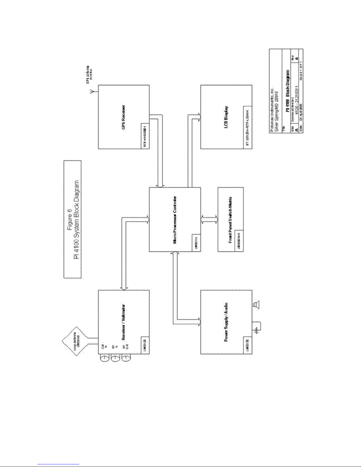
Functional elements: The PI 4100 Functional Block Diagram, Fig. 1, p. 10, shows the PI 4100's
functional elements.
6
Page 8

1.2 PI 4100 KEY FEATURES
● 126 dB dynamic range measuring receiver
● Digitally synthesized tuning in 1.0 kHz increments
● Spectrum display to facilitate various measurements (Field Strength and Spectrum occupancy) in a
single instrument
● Provisions for a third party calibration check, using their laboratory standards, when it is impractical
to return the instrument to the manufacturer for calibration
● Data acquisition software and PC interface to enable the collection, analysis, and e-distribution of
field measurements. (This feature anticipates the future acceptance of data e-filing by federal
regulatory agencies.)
● Magnetic compass to aid in the initial orientation of the integral loop antenna
● External RF input port (BNC) so that the instrument can be used as a stand-alone calibrated tuned RF
Voltmeter
● External RF output port (BNC) so that the buffered output from the loop antenna can be used to drive
external detectors and spectrum display devices
● USB port for downloading data from the PI 4100 internal memory to a compatible computer
● Comma separated data format for ease of importation to third party commercial software
● DC Field strength output for external recording
● DRM and HD Radio measurement capability with automatic correction
7
Page 9

1.3 SPECIFICATIONS
Field Strength Measurement
Frequency Range 520 kHz to 5.1 MHz or 200 kHz to 5.1 MHz, calibrated
Minimum frequency step 1.0 kHz
Measuring accuracy:
AM & Simulcast DRM ± 3 %
Pure DRM ± 6 %
Field strength measuring range:
AM & Simulcast DRM 28 dBuV/m to 154 dBuV/m (25 μV/m to 50 V/m)
Pure DRM, 4.5/5 kHz BW 33 dBuV/m to 146 dBuV/m
Pure DRM, 9.0/10 kHz BW 36 dBuV/m to 146 dBuV/m
Pure DRM, 19/20 kHz BW 39 dBuV/m to 146 dBuV/m
Measurement units μV/m-mV/m-V/m; mV/m only;
dBuV/m (dB above 1 µV/m)
Measurement bandwidth 1.0 kHz @-3 dB
Image rejection ratio 60 dB
Spurious rejection 75 dB
Harmonic measurement
Harmonics, menu-selected 2nd, 3rd, 4th, 5th
Measurement range to -80 dBc or lower, for carrier FS of (0.3 – 3) V/m
Spectrum Display
Modes Norm (referenced to center freq FS)
Center frequency range Same as FS frequency range
Span (Sweep width) 128 kHz, 45 kHz
Resolution bandwidth 1 kHz
I/O Ports:
Data output jack USB B jack
Cal In jack BNC, nominal calibration input 700 mV rms
RF In jack BNC, RF input and dc FS output
RF Out jack BNC, RF output and dc cal detector output
Headphone jack Audio jack, 3.5 mm
Battery charging jack Power jack, 2.1 mm
Peak (Norm with peak hold)
Abs (displays 20 - 140 dBuV/m FS)
8
Page 10

RF Voltmeter (RF In jack)
Input impedance 2500 Ω
Voltage range 30 μV to 40 V rms
Measurement units μV-mV-V; mV only; dBuV
RF Out 28 ±2 mV rms in 50Ω for 1 V/m FS, 200 kHz – 5.1 MHz
DC Field Strength output Proportional to dBuV/m, 1.0 Vdc @ 100 dBuV/m with a
1 MΩ load (10 mV/dB)
Audio outputs For AM and Simulcast DRM only:
Front panel speaker
Headphone jack, 3.5 mm, mono or stereo
(use disconnects speaker), up to 4.0 V p-p max output
Data items stored 28 items, listed in Users Guide Sec. 4.5.6
Battery power supply
Battery type Rechargeable NiMH, 7.2 V, PI supplied
Battery operating time 5 hours min., new battery
Battery recharge time 3 hours typical for full charge
Charging supply 11 - 15 Vdc, 1.2 Amperes min., 2.1 mm plug
Alternative battery Six AA cells in a PI-supplied battery holder
Environmental characteristics:
Operating temperature range 0ºC to 50ºC dry, RH 95% (non-condensing)
Operating altitude Up to 13000 ft. (4700 m)
Dimensions and weight:
Length, Width, Height L: 15 in, 38 cm W: 7 in, 18 cm H: 11 in, 28 cm
Weight 5.5 lb, 2.5 kg
9
Page 11
10
Figure 1. PI 4100 Functional Block Diagram
Page 12

2. Receipt, Inspection, and Reshipment
2.1 Unpacking
The PI 4100 is packed in a custom shipping carton. Inspect the carton for any signs of serious
damage. Report any damage to the shipping company.
Carefully remove the PI 4100 from the shipping carton. A User’s Guide, a charger power supply
with power cord, an in-vehicle charging cable, a battery holder, a USB cable, and a CDROM are included
in the carton. Please retain the carton, the plastic foam insert holding the PI 4100, and other packing
materials in case the unit and accessories must be shipped. The foam insert can be used in the Pelican
1610 hard case, see Appendix 4 for details.
The PI 4100 is ready for operation as delivered. See Section 4 of this Manual for operating
instructions.
WARNING
In all locations where power receptacles have a ground pin socket, the PI 4100 recharging
power supply’s power input ground terminal must be connected to the receptacle ground pin
socket. Failure to use a grounded outlet may result in improper operation or a safety hazard.
2.2 Reshipment to factory
If a PI 4100 must be returned to the factory it is best shipped in its original carton and packing
materials or in a Pelican 1610 case. Shipping cartons can be ordered from the factory if suitable
packaging is not available. Contact information can be found below and in Section 5 of this Guide.
2.3 Service and Warranty for Equipment and Accessories
Warranty: Potomac Instruments, Inc., warrants each new equipment to be free of defects in
material and workmanship, for a period of one (1) year after the date of receipt of the equipment in
satisfactory working condition. Any instrument which is found within one year not to meet the foregoing
standards after examination by our factory or representative, will be repaired, or at the option of Potomac
Instruments, replaced without charge. This warranty does not apply to equipment which has been altered,
improperly handled, or damaged after receipt.
If the PI 4100 fails to perform properly, initially or after a period of use, or if it requires factory
recalibration: if there is a local factory-authorized dealer or service facility, first contact the dealer or
facility. A technician there will determine the best procedure to deal with the problem, in consultation
with the factory if necessary. Otherwise, contact the factory directly. In either case it is recommended to
use the use the factory online RMA (Returned Material Authorization) system by going to the Potomac
web site at http://www.pi-usa.com, and clicking Request Service - On-line RMA Request. For units
that are not under warranty, repair cost estimates will be provided, and authorization to proceed will be
obtained from the customer before repairs are carried out. If return to the factory is not possible, Potomac
Instruments will work with the authorized service facility or user to complete the repair, and will supply
technical data and parts as necessary.
2.4 Contact information
Factory:
Potomac Instruments inc.
Attn: Service Dept.
7309 Grove Road, Unit D
Frederick, MD (Maryland) 21704
Phone: +1-301-696-5550
Fax: +1-301-696-5553
email: service@pi-usa.com
http://www.pi-usa.com
11
Page 13
3. Controls, Indicators, and External Ports
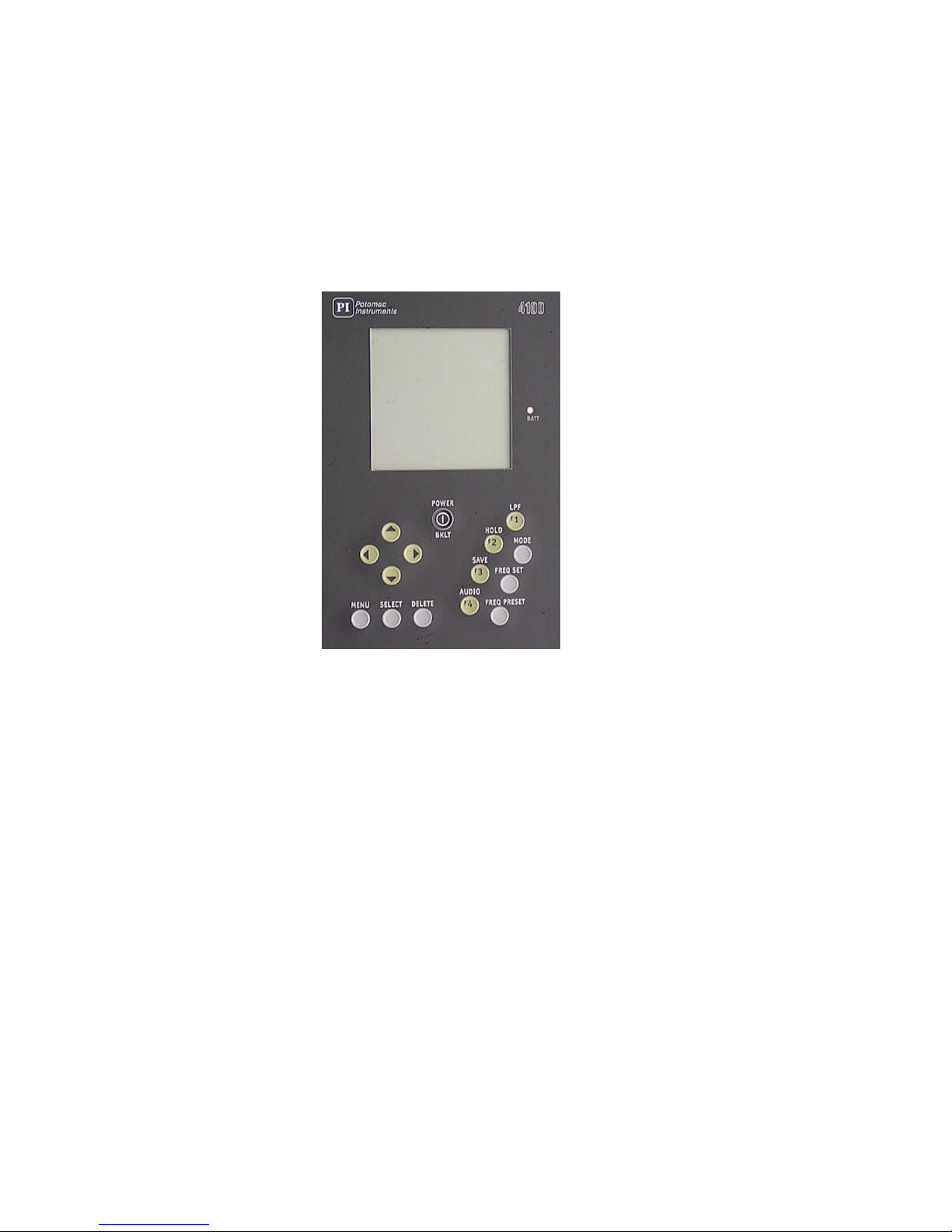
3.1 Front Panel
Refer to Figure 1 or to the PI4100 itself for the following discussion. Each control is described
below, starting with the Power/Bklt key, and moving counterclockwise aound the panel to the other
keys..
Figure 1. PI 4100 Front Panel Controls and Indicators
POWER/BKLT: Turns the 4100 on (press until screen text appears) and off (press until screen text
disappears). Turns the display backlight on and off, a short press for both.
UP and DOWN arrowhead keys: These keys (1) move a reverse video cursor to step through the
choices available in the menu and submenus, and (2) step through the available values of a digit or
character, 0-9 and/or A-Z.
LEFT and RIGHT arrowhead keys: These keys (1) for some menu items, move an underline cursor to
select options; (2) for some menu items, move a reverse video cursor to select a number or character to
change; and (3) for FREQ SET, move an underline cursor to select digits to change.
MENU: When in the field strength screen or a spectrum screen, press to display the menu of operational
and setup options; press again to go back to the previous screen. For details see Sec. 4.3, p. 24.
SELECT: Used in menu operations to confirm a selection from a list, to confirm the choice of an item to
modify, and to confirm that the modification is complete, all in accordance with on-screen instructions.
DELETE: Used to review the data records stored in the PI 4100, and (using SELECT) to delete selected
data records. For details see Sec. 4.5.2, p. 27.
AUDIO/F4: Turns audio in the speaker or headphones on and off, a short press for on and a long press
for off. For audio on, short presses step the sound level through four steps. For F4 see FREQ PRESET.
12
Page 14

SAVE/F3: Used to save a measurement and associated data in internal memory. Press once to review
and change the associated data on the Save screen, and press again to complete the Save operation and go
back to the Field Strength screen. For details see Sec. 4.2.4, p. 19. For F3 see FREQ PRESET.
HOLD/F2: When pressed, the field strength value at that time is held on the display and in temporary
memory. For details see Sec. 4.2.4, p. 19. For F2 see FREQ PRESET.
LPF/F1: Controls stepping through three low-pass filter choices for three degrees of field strength value
smoothing. For details see Sec. 4.2.5.3, p.20. For F1 see FREQ PRESET.
FREQ PRESET: Allows quick selection of any of four previously stored frequencies which are shown
on the display as F1, F2, F3, and F4 after FREQ PRESET is pressed. Selection is made by pressing
one of the keys marked F1, F2, F3, or F4 as indicated above. For details see Sec. 4.2.1.3, p. 17.
FREQ SET: Allows setting the receive frequency to any available value by setting each digit of the kHz
number on the display to the desired value. For details see Sec. 4.2.1.3, p. 17.
MODE: From the Field Strength screen, steps the display through three spectrum display modes and
back to the Field Strength screen. For details see Sec. 4.2.7, p.22.
BATT LED: Signals by flashing that the 4100 will soon turn itself off because of low battery voltage and.
the battery pack needs to be recharged. For details see Sec. 4.4.1, p. 26.
13
Page 15
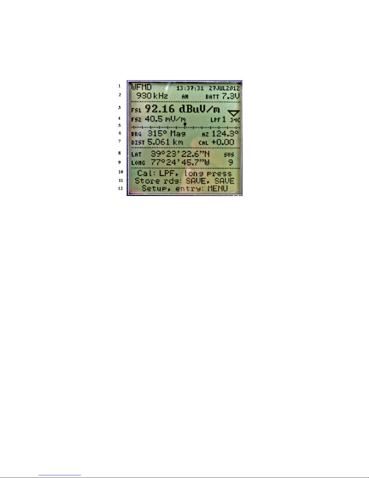
3.2 Primary Display Screen Elements
Refer to Figure 2 or to the PI4100 itself for the following discussion. Screen element descriptions are
given below with reference to horizontal lines of text, starting at the top with Line 1 and reading from
left to right in each line. For more detail on an item refer to Sec. 4, Operation.
Figure 2. PI 4100 Field Strength display
Line 1: Call sign of the selected station; Time and date from GPS (UTC + Offset).
Line 2: Frequency of the selected station; Modulation type; Battery voltage.
Line 3: Field strength value and units; Field strength trend indicator, points up for increasing, down
for decreasing field strength.
Line 4: Field strength value and units; LPF setting, degree of field strength smoothing, 1, 2, or 3;
internal temperature, ºC..
Line 5: Analog field strength indicator, each major division indicates 1 dB (12%) change.
Line 6: Bearing (magnetic) of the station from the PI4100; Azimuth of the PI4100 from the station.
Line 7: Distance of the PI4100 from the station; Internal correction value (for reference only)
Line 8: Latitude of the PI4100, degrees/minutes/seconds, from GPS.
Line 9: Longitude of the PI4100, degrees/minutes/seconds, from GPS; Number of GPS satellites in
view.
Lines 10, 11,12: Prompts for the operator, on manual self-calibration, storing a reading, and menu use.
Prompts vary with screen function.
14
Page 16
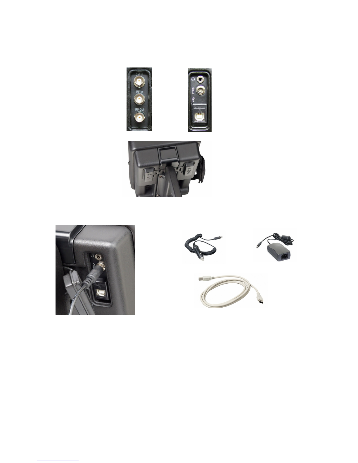
3.3 Rear Panel Signal and Power Ports
RF calibration input Headphone jack
RF voltmeter input Battery charging jack
DC field strength output
Buffered antenna RF output USB data port
Cal detector dc output
Figure 3. PI 4100 Rear Panel Signal and Power Ports
Figure 4. Charger Cable installed for charging Figure 5. Battery charger and Interface
Cables supplied
15
Page 17

4. Operation
4.1 FIRST- TIME OPERATION
After unpacking the 4100, a trial run will help a new user to become familiar with its operation.
The following is suggested:
Connect and charge the supplied battery pack, if either is necessary.
Adjust the compass index
Go outdoors and try some field strength measurements.
Review the menu options and enter the time offset between UTC and local time.
Enter data for a station to be measured.
Use GPS-derived data and the compass to orient the 4100.
Make and save some field strength measurements.
Download the measurement results to a computer.
Details on operating the 4100 can be found throughout this Guide, therefore browsing through the
Manual may reveal information of special interest.
Connect the battery:
The 4100 is shipped with its battery pack connected except in unusual circumstances. If it is
shipped with the pack disconnected (there is no response on pressing the POWER key), connect the
battery as follows:
Open the battery access door at the bottom of the front panel by pulling the upper left-hand
corner of the door away from the panel.
Locate the cable on the battery as well as the cable to the unit above. Both cable ends are
usually found under the battery, after the battery is removed.
Plug the connectors on these two cables together and reinstall the battery with the mated
connectors under the battery.
Close the battery door, pressing in on first the sides and then the top of the door so the flange on
the inside of the door is caught behind the panel edges.
Adjust the compass index:
The 4100's compass has a red vertical index line facing the operator, which should be on center,
aligned with the joint line of the two halves of the compass mount. If it is not so aligned, rotate the
compass in its mount to bring the index line into alignment.
Adjust the hand strap:
To adjust the length of the strap, separate the two halves of the wide padded part of the strap,
which are held together by hook-and-loop material. Pull the lower strap end loose from the pad,
reposition it in the bottom metal loop as desired, press the strap back onto the pad it was removed from,
and press the two padded halves together. The strap can be moved to the right-hand side of the 4100 by
removing and reinstalling the screws that fasten the strap mounting rings to the case.
Turn on the 4100 and make a measurement:
Turn the 4100 on: Press POWER/BKLT until text appears on the display. If the battery has
enough charge the main screen appears after a few seconds. If nothing appears on the display the pack
must be charged, see Battery information, Sec. 4.2.5.. When text appears look for the battery voltage
readout BATT 7.2V (7.2V is a typical value) at the right side of the screen near the top. If the voltage is
7.0 or more, go ahead with measurements. Sec. 3.2, p. 14, describes other screen elements.
16
Page 18

Set the frequency: Change from the factory set 500 kHz to the frequency of the desired station.
A stronger one is better for the first try: Press FREQ SET; a cursor line appears under the 10 kHz digit
(for 9 kHz channel spacing, the 1 kHz digit). Set that digit to the desired value using the up & down
arrow keys (UD). Use the left arrow key to move the underline to the next digit to be changed, and
change it in the same way. Repeat until the display shows the desired frequency.
Press AUDIO to hear the station's audio: The level does not change with field strength. Short
presses of AUDIO will change the sound level through four steps and a long press turns it off. Audio
quality is limited by the receiver's narrow bandwidth and the speaker's small size.
Start Self-Calibration: Press and hold the LPF/F1 key until CAL appears in a box. Self
calibration at the selected frequency proceeds and ends with CAL OK in a box if all is normal.
Measure Field Strength: orient the loop antenna for maximum reading (while keeping it
vertical) by using the analog indicator, a small block which moves right or left as the level increases or
decreases. There is also a trend indicator with an arrow that points up when level is increasing and down
when it is decreasing. To reduce rapid variations in the reading, usually due to modulation, press LPF; on
the display LPF1 changes to LPF2. This reduces variation and slows response time by applying a
lowpass filter. Press LPF again to obtain more filtering; LPF2 changes to LPF3. A third press of LPF
returns to LPF1 for the least filtering.
When the reading is maximum press SAVE to save the reading. The value is held internally
while the screen changes to the Save Screen, in which additional data can be entered and saved with the
measurement. On this screen the operator has the option to enter the pattern being measured, a
letter/number code for the measurement location, operator's ID, and a 14-character note. After the desired
entries are made, press SAVE again to complete the operation and return to the field strength screen.
GPS use: In an outdoor location where GPS reception is possible, latitude and longitude will
appear on the display (the first fix after the 4100 has been shipped a long distance may take several
minutes). Distance, azimuth, and bearing can be displayed if the latitude, longitude, and magnetic
variation are entered in the 4100 for the transmitting antenna location. To do this, press MENU, go to Tx
add, and enter the data. For more detail see Sec. 4.2.2, p.18. The 4100 can now be oriented for
measurements by making the compass reading equal to the bearing value on the display.
Downloading data to a computer: To download data, first, install the 4100 Data Downloader
program supplied with the 4100 and start the program (see Sec. 4.5, p.28). A program window appears
with four buttons indicating the tasks the program can perform. When a USB cable, Type A to Type B, is
connected between the computer and the 4100, “PI 4100 connected” appears at the top of the program
window and the 4100 display blanks. On the computer click the top “Download...” button; specify the
file name of the .csv file that will contain the data and where that file is to be stored. The download then
proceeds. Downloaded data may be viewed in the program or by opening the .csv file in a spreadsheet
program.
To turn the 4100 off, press and hold down POWER/BKLT until the screen text disappears after
about two seconds.
17
Page 19

4.2 PI4100 Operating procedure details
4.2.1 Setting the operating frequency:
Frequency can be set in these ways:
Accept the turn-on setting
MENU - Tx select
FREQ PRESET key
FREQ SET key
MENU - Harmonic select
4.2.1.1 Turn-on: A new 4100 turned on for the first time shows the factory setting, 500 kHz. If
the unit has been used: if it was on a frequency chosen using Tx select (see below) at turn-off, it will be
on that frequency when next turned on. If it was on a frequency set using FREQ SET at turn-off, when
turned on it will be on the frequency most recently selected using Tx select, or on 500 kHz.
4.2.1.2 Use MENU-Tx select to make a radio station for which data has been stored the active
station. The station's frequency and call sign appear on the display, and its antenna location and
declination is used to calculate distance, azimuth, and bearing. For DRM and all-digital HD stations a
correction is added to the field strength reading. A new unit will have no station data stored.
To use Tx select: Press MENU; with the cursor on Tx select press SELECT; use the up-down
keys to select a station: press SELECT; press MENU. If the desired station is not shown, use Tx add in
the menu to enter it, see Sec.4.2.2. Self-calibration will take place automatically.
4.2.1.3 Use FREQ PRESET to change to a new frequency. To store a frequency as a preset to
use later, first use MENU-Tx select to go to that frequency (only frequencies stored in Tx select can be
made presets). Then press FREQ PRESET; press one of the F1 - F4 keys and hold it down until you
hear a beep and the display shows the new frequency. Repeat this for other frequencies desired as presets.
To go to a preset frequency, press FREQ PRESET; the display shows the available presets.
Briefly press the F1 … F4 key for the desired frequency, do not hold the key down. If station location
data has been entered for that frequency, and GPS reception is possible, location-related data, date, and
time appear on the display. Self-calibration will take place automatically.
4.2.1.4 Use FREQ SET to change to a new frequency. To set a frequency: Press FREQ SET;
use up-down keys to change the frequency digit over the underline cursor; press the left key to move the
cursor to the next digit, changing its value the same way; repeat as needed. The 4100 will then receive a
signal on the new frequency but no location-related or time data will appear. For accurate measurements
press LPF to initiate self-calibration, holding the key down until CAL appears in a box.
4.2.1.5 Use MENU-Harmonic to go to a harmonic of the current frequency. To select a
harmonic, press MENU and use the down arrow to go to Harmonic: 1 2 3 4 5. Use the right arrow key
to move the underline cursor to, for example, 3 for the third harmonic, and press MENU. The receive
frequency then changes to three times the displayed frequency, and on the display, 3x appears to the left
of the frequency. If a new frequency is selected by using Tx select or FREQ PRESET, the harmonic
selection changes to the fundamental. For more detail see Sec. 4.2.6, p.23, Measuring Harmonics.
4.2.2 Entering and changing station data for GPS use
To use the internal GPS receiver to obtain distance and azimuth of the measuring point from the
transmitting antenna, and to use the compass for loop antenna aiming, data must be stored in the 4100 for
the station to be measured. Data is stored, modified, and retrieved by using the menu items Tx add, Tx
edit, and Tx select. As many as 50 stations may be entered. Station data can be entered by using the
front-panel keys or by using the Data Downloader program, see Sec. 4.5.4, p. 28. If the GPS derived data
is not needed, measurements can be made without this data-entry step by using FREQ SET to set the
frequency.
18
Page 20

4.2.2.1 To enter station data using MENU – Tx add:
Press POWER/BKLT to turn on the 4100.
Press MENU after the field strength screen appears; the menu screen appears.
Press the Down arrow key to go to Tx add; press SELECT. The Tx data entry screen appears,
listing six data items to be entered, and with the reverse video cursor on the first item, Call - Site. Call is
the station identifier; if there is more than one antenna site for the call, each one can have a separate Tx
entry with the same call but a different dash number. As many as eight characters can be entered. Press
SELECT; reverse video appears on the first character. Press the Up key to scroll through the numbers
and the alphabet, or press the Down key to scroll backwards, to change this character to the desired one.
Press the Right arrow key to go to the next character and change it the same way. Continue this
procedure until all characters are as desired, then press SELECT to exit Call-Site.
Press Down to go to Freq, and press SELECT. Proceed as for Call-Site, using the arrow keys
to change each frequency digit to the desired value. When done press SELECT, as before, to exit Freq..
At this point it is possible to exit Tx add, if the location data is not available or not of interest,
and the new entry will appear in the Tx select list.
To enter location data, move to each of the remaining data items and enter the required data.
Latitude and Longitude are the transmitting antenna location coordinates in degrees, minutes,
and seconds.
Var is the magnetic declination, also known as variation, the angular difference in degrees and
minutes between the bearing of true north and magnetic north. It can be calculated from the latitude and
longitude at this NOAA web site: http://www.ngdc.noaa.gov/geomagmodels/Declination.jsp.
Modulation is the modulation system used by the station. Going to Modulation and pressing
SELECT gives the available choices. AM refers to normal double-sideband amplitude modulation. DRM
with a number refers to Digital Radio Mondiale; the number is the occupied bandwidth in kHz. HD-ad
refers to the all-digital mode of HD Radio. When a DRM or HD station is selected in the 4100, a
correction is automatically added to the field strength reading to account for the difference between the
measuring bandwidth, 1.0 kHz, and the occupied bandwidth. The DRM correction would be valid for any
digital modulation system of the same bandwidth in which the power per unit bandwidth is uniform
across the band.
When the required data has been entered, press MENU to go back to the main menu, and
press MENU again to return to the field strength screen. The station just entered becomes the active
station, meaning that the receiver is tuned to its frequency. Its antenna coordinates are used to calculate
distance, the azimuth of the 4100 from the station, and the magnetic bearing of the station from the 4100.
4.2.2.2 To enter station data using the Data Downloader Program: With this program, data
can be entered from the keyboard of a connected computer. To do this see the Downloader program
instructions, Sec. 4.5.4, p. 28.
4.2.2.3 To change existing station data: MENU – Tx edit: Press MENU, go to Tx select, and
select the station needing a change. Press SELECT to return to the menu, go to Tx edit, and press
SELECT again. All data items for the selected station can then be entered or edited as described above
for TX add.
19
Page 21

4.2.3 Self-calibration, automatic and manual
Automatic calibration: The 4100 calibrates itself using an internal calibrating source. This
takes place automatically when the unit is turned on, and also when the selected station is changed by
using Tx select or FREQ PRESET.
Manual calibration: To initiate calibration at any time press LPF, holding the key down until a
blinking CAL message appears on the display, followed by CAL OK. Do this when the frequency is
changed using FREQ SET since it will not be done automatically. Do it immediately before critical
measurements, especially when the 4100 has been subjected to a large temperature change. Manual
calibration is intended to be used only for field strength measurements, not for the RF Input mode.
CAUTION: For accurate measurements, all parts of the 4100 must be at least 12 inches (30 cm)
from any large metal surface during self-calibration. If the unit is turned on while resting on a metal
surface, and self-calibration takes place, its readings when handheld will be about three percent too high.
It is best to turn the 4100 on and change its frequency selection after the unit is positioned for
measurements.
How self-calibration works: When LPF is held down, CAL appears blinking in a box on the
display, and the 4100 checks to see if the received signal is large enough to affect the calibration. If so,
the receiver frequency is shifted a few kHz and the check repeated; when this test is passed, the internal
calibrating source is turned on and injected into the loop antenna; the resulting field strength value is
compared to a factory-set reference. The dB difference between the two, which is the CAL number seen
on the display, is saved and added as a correction to all field strength dBuV/m readings until the next selfcalibration. Voltage unit readings are calculated from the corrected dBuV/m values. CAL OK appears in
a box on the display to show that the process is complete, and the new CAL value is displayed. If there is
a problem with the calibration, NO CAL 1 (received signal on the cal frequency too high) or NO CAL 2
(change from the previous CAL value too great) may appear instead of CAL OK, and the previous CAL
value will be retained. The CAL value indicates the receiver internal gain correction; the operator does
not need to make use of it.
4.2.4 Saving measurements: SAVE and HOLD
4.2.4.1 To save a measurement, press SAVE. All screen data is held at the values existing
when SAVE was pressed. The Save screen appears, which allows operator- entered data to be stored with
the measurement. Pressing SAVE a second time stores the measurements together with the following
optional operator notations:
Pat (pattern): Gives the antenna pattern in effect for the measurement, following standard US
practice. The choices are Dy (day), Nda (non-directional), Nt (night), Cr (critical hours), and -- (no
pattern designation). Choose one by using the left and right arrows to move the underline cursor to the
desired pattern. Then press the down arrow to go to the next screen item.
Meas. Point: Enter a predetermined code to identify the measurement point. Enter up to four
characters following the same method given above for entering a call sign for Tx add (see p. 19).
Radial: Enter the radial angle associated with the measurement, if applicable (the azimuth
shown on the field strength screen should be close to this value).
Initials: Enter the initials or other ID of the person making the measurement.
Data point: This is a number that steps up one unit each time a measurement is saved to
provide an identifying number for the measurement. To reset the number to a desired value at the start of
a series of measurements use the methods described for Tx add above. To see the number of the last
measurement saved, to prevent duplication of numbers, press DELETE.
Note: A note of up to 14 characters may be entered, using the Tx add call sign methods. This
could be the call sign of a station measured using FREQ SET, not otherwise saved.
20
Page 22

4.2.4.2 Completing the Save: Press SAVE a second time to complete the Save process and
return to the field strength screen for the next measurement. The 4100 allows up to 250 measurement
records to be saved before some records must be downloaded to make space for more. At the top of the
Save screen the number of measurements that can be saved at any time is given as NNN Free. To reduce
the possibility of data loss it is advisable to download saved data as soon as possible, using the PI 4100
Data Downloader program supplied (see Sec. 4.5).
4.2.4.3 Entering Save screen data before measuring: Data can be entered on the Save screen
before starting measurements, which saves time during measurements. To do this press SAVE once,
enter the data, and press MENU to go back to the field strength screen. All Save screen data is held for
all measurements until the operator changes the data, except Data point, which automatically increases
by one as each measurement is saved. When measuring, press SAVE to hold the measurement data and
view the Save screen, which will show the previously entered data. Edit as necessary as described above
and press SAVE a second time to save the data.
4.2.4.4 The HOLD key: Press HOLD to ‘freeze’ everything on the field strength screen at the
instant the key is pressed; all values on the screen remain fixed until further action is taken. Press HOLD
again to return to normal operation without saving the data, or press SAVE to save the data and return to
normal operation. The operator may make a measurement and press HOLD when satisfied that the
measurement is accurate, and then decide whether to save it.
4.2.4.5 Viewing and deleting saved data: To view measurement data records saved in the
4100, press DELETE. The screen now shows the most recent record and gives on-screen instructions for
going to other records. Press the up arrow key to go to an earlier record or hold the key down to step
through the saved records. Press the left arrow key to go to the earliest record. To delete a record, make
it the one shown on the screen and press SELECT. To go back to the field strength screen press MENU.
4.2.5 Measuring Field Strength
4.2.5.1 Field strength units: FS1 and FS2 on the display express the same measurement in
different units, which are selected for each as follows: press MENU; press Fld Str 1 or Fld Str 2; press
SELECT; move the cursor to the desired units; press SELECT. The choices are voltage units, uV-mV-
V/m or mV/m only, or dB units, dBuV/m (dB above 1 uV/m). Although voltage units are standard in US
practice, dB units can be easier to interpret when the value is fluctuating because a one unit change in the
last digit always represents approximately a one percent change in value. When it is desired to find the
dB difference between two values, having dB units simplifies the calculation. FS1 and FS2 values are
both saved when a measurement is saved.
4.2.5.2 Loop antenna orientation: When measuring, the loop antenna can be oriented for the
highest reading, or it can be pointed at the transmitting antenna by making the compass reading equal the
displayed bearing value. When using the compass, be sure that no nearby iron or steel objects are
affecting the compass, and that declination (variation) is entered correctly. Pointing at the antenna may
give a lower value if there is significant reflection from conducting objects in the area. If this is the case,
both values can be saved for analysis after downloading. Standard practice is to keep the loop antenna
plane vertical; this also can be varied and the results saved.
4.2.5.3 LPF use: Low-pass filtering to reduce fluctuation in the displayed value is available by
using LPF to step through three choices. Approximate values of the time it takes for the reading to reach
its final value are for LPF1, 0.5 sec; for LPF2, 1.5 sec; and for LPF3, 5 sec. When the FS reading goes
below 35 dBuV/m the 4100 switches from LPF1 to LPF2. When cochannel interference is present, and
the frequency difference is 2 Hz or greater, use of LPF3 allows measurements when the desired signal
exceeds the undesired signal by 4 dB or more.
Another way to deal with varying readings is to save several readings and average them after
downloading.
21
Page 23

4.2.5.4 DC field strength output: A dc voltage output proportional to dBuV/m is available at
the center pin of the RF In BNC jack. With a high-resistance load the voltage is approximately 10
mV/dBu, or 1V for 100 dBuV/m, with a maximum range of 0.2 to 2.0 V. The source resistance is 10,000
Ohms. A 100ua full scale analog meter could be connected between this point and ground for remote
reading. This output can be used while an external RF input signal is connected by feeding the signal to a
T junction through a coupling capacitor.
4.2.5.5 Temperature effects: The low-temperature limit for display operation is -20C/-4F, but
measurements become difficult as the temperature approaches these values because the display response
time becomes very slow. Battery performance is reduced as well. A good cold-weather strategy is to
keep the 4100 in a warm environment as long as possible and to transport it an insulated carrier so its
exposure to cold is minimized. The high-temperature limit is +50C/122F, also set by the display. In
warm weather it is advisable to minimize the time the unit spends in a closed vehicle in the sun, or the
time spent in direct sunlight. The temperature shown on the display is the processor temperature, which
increases to several degrees above ambient with operation.
4.2.5.6 Measuring pure DRM transmissions: In pure DRM transmissions the transmitted
power is uniformly distributed throughout the assigned signal bandwidth, which may be 4.5, 5, 9, 10, 19
or 20 kHz. Since the 4100 measures the power in a 1.0 kHz bandwidth, the total power received is
greater than the measured power in a 1.0 kHz bandwidth by a factor equal to the signal bandwidth in kHz.
Thus the observed field strength in dBuV/m in the 4100 must have added to it a correction quantity
10logB (where B is the DRM signal bandwidth in kHz) to obtain the total received field strength value to
be displayed. Voltage unit values for display are calculated from the dBuV/m values. This correction is
done automatically in the 4100 (for operating software versions 2.3.06 and higher) when a station is
selected from the Tx select list which has the appropriate modulation entry (see Sec. 4.2.2.1, p.19 ). The
correction values are: 4.5&5, 6.8dB/2.19; 9&10, 9.8 dB/3.1; 19&20, 13.0 dB/4.4. Simulcast DRM
transmissions with full carrier do not require this correction and are treated the same as AM signals.
4.2.5.7 Measuring HD Radio All-Digital transmissions: For this signal the carrier but only
part of the sideband power are within the 4100’s 1 kHz bandwidth. A correction must therefore be added
to the measured value to obtain the total field strength. This correction has been calculated to be 3.9 dB
for dBuV/m units or a factor of 1.57 for voltage units. In PI 4100s with software version 2.3.07 or higher
this correction is added automatically if the station data has been entered using Tx add (see Sec. 4.2.2.1,
p. 19) with modulation type HD-ad.
4.2.5.8 Low measuring limit: In the absence of significant ambient RF noise the 4100's field
strength noise floor is typically 10 - 14 μV/m (20 - 23 dBuV/m) and the field strength of AM and
Simulcast DRM signals as low as 25 μV/m (28 dBuV/m) can be measured with approximately ±5 per
cent error. If the noise indication exceeds 14 μV/m at a no-signal frequency near the signal to be
measured, because of ambient RF noise, the low limit for field strength accuracy is correspondingly
higher. For pure DRM signals the low limit for measurements is higher because only the signal within a
1.0 kHz band is measured; the full signal is greater as explained in Sec.4.2.5.6 above. Based on
measurements of a simulated pure DRM signal with a typical PI4100, the low limit for accuracy is, for
bandwidths of 4.5 and 5 kHz, 45 μV/m (33 dBμV/m); for 9 and 10 kHz, 63 μV/m (36 dBμV/m), and for
19 and 20 kHz, 89 μV/m (39 dBµV/m).
4.2.5.9 High measuring limit: The 4100's autoranging input attenuator allows measurement of
very high AM field strengths, up to and beyond the recommended limits for worker exposure, 600 V/m at
or below 1 MHz and (600/f in MHz) above 1 MHz. Potomac Instruments strongly recommends that 4100
users stay within these limits. In high field work, near an antenna tower, electric field strength readings
may not be accurate because the 4100's loop antenna responds to the magnetic field and is calibrated to
read electric field on the assumption that the ratio of electric to magnetic fields is 377, as it is in free space
or the antenna far field. This ratio may or may not hold in the near field.
22
Page 24

4.2.5.10 Frequency range for measurements: While the 4100's specified frequency range for
accurate measurements is 200 kHz - 5.1 MHz, it can be used outside this range. The frequency range for
which the unit is calibrated is shown on the nameplate on the bottom of the case and on the screen that
appears for three seconds when the unit is first turned on. At the low end it can be used as long as manual
self-calibration gives a CAL OK message, typically below 200 kHz, and calibration down to 200 kHz is
available. At the high end the 4100 can be used with reduced accuracy at least to 8.5 MHz, so 5th
harmonic measurements of 1.7 MHz are possible.
4.2.6 Measuring Harmonics
4.2.6.1 Measurement conditions: The PI 4100 can measure broadcast harmonics with full
accuracy for harmonic frequencies up to 5.1 MHz and with reduced accuracy to 8.5 MHz. For accurate
measurements the received signal must be large enough that the harmonic to be measured will be above
the 4100’s noise floor, but not large enough to cause significant harmonic generation within the 4100.
The range of fundamental frequency field strength values that satisfy these conditions, depending on the
target harmonic ratio it is required to equal or exceed, is as follows:
Target harmonic ratio: 60 dB: Fundamental field strength must be: 30 mV/m to 12 V/m
70 dB 100 mV/m to 6 V/m
80 dB 300 mV/m to 3V/m
If local RF noise picked up is greater than the 4100’s noise floor, the lower field strength limit needs to be
greater than stated above. Generally, greater fundamental field strength is better; the best value for
accurate harmonic ratio measurements is approximately 2 V/m.
4.2.6.2 Measurement procedure:
● Use Tx select to select the desired station.
● Position the 4100 and orient it for maximum field strength, near 2 V/m if possible.
● Press MENU and move the cursor to Harmonic.
● Move the underline cursor to the desired harmonic multiple, for example 3.
● Press MENU to return to the field strength screen.
3x now appears on the display to the left of the frequency, and the 4100 is set to receive at three times the
displayed frequency. The received field strength is displayed in dB relative to the fundamental field
strength, or dBc, so a harmonic 72 dB below the fundamental will display as -72 dBc.
4.2.7 Spectrum mode operation
The 4100 can display the spectrum of a signal as a plot of received amplitude vs. frequency
over a span of 128 kHz, which is centered on the frequency shown on the field strength screen at the time
MODE is pressed (see below). It does this by stepping its operating frequency in 1 kHz steps across the
span, producing a plot on the display in 1 dB amplitude steps. Amplitude values are held internally with
0.1 dB resolution. The measurement bandwidth, or resolution bandwidth, at each frequency is fixed at
1.0 kHz. Each amplitude value is the average of the signal received over a period of approximately 20
milliseconds. The total amplitude range available is approximately 128 dB. These parameters are at
variance with NRSC requirements for spectral occupancy measurements, which call for a 300 Hz
resolution bandwidth and peak hold without averaging.
Spectrum modes: There are three spectrum modes, designated Normal, Peak, and Abs
(meaning Absolute). From the field strength screen press MODE to go to Normal, press it again to go to
Peak, press it again to go to Abs, and press it again to return to the field strength screen.
Normal mode: This is a plot of amplitude in dBc (dB below the center frequency carrier
amplitude) with the center frequency point at the top center of the plot.
23
Page 25

Peak mode: This is a dBc plot like the normal mode but with peak hold added. Each point
remains at the highest value it reaches during any sweep since the start of the plot, and a timer shows the
time elapsed since the plot was started.
Absolute mode: This is a plot of field strength value in dBuV/m vs. frequency, with 20 dBuV/m
(10 uV/m) at the bottom of the screen and 148 dBuV/m (25 V/m) at the top, without peak hold. This
mode is the most useful for showing what signals are present whether or not there is a signal at the center
frequency.
Marker: All modes have a marker to give precise amplitude and frequency values. The marker
is a short vertical line which extends above the plot and is moved across the plot by the right and left
arrow keys. As it is moved, the frequency difference from center and the amplitude value is displayed.
There is also a very short cursor that moves across the plot as the frequency is stepped.
Span (sweep width): In the menu the span can be shortened from 128 kHz to 45 kHz, which
gives 2.8 times as many sweeps per minute of the central part of the plot. The central part occupies the
same width on the display space as it does for the 128 kHz span. To change the span to 45 kHz, press
MENU, go to Spectrum kHz: 128 45, and use the right arrow key to move the underline cursor to 45,
or the left arrow key to change back to128. Press MENU a second time to return to the spectrum screen.
4.2.8 Measuring RF voltage: the RF In BNC jack
General: The PI 4100 can serve as a tuned RF voltmeter to measure the level of a signal
connected to its RF In BNC jack, with approximately ±5 per cent accuracy over a range of 30 microvolts
(32 dBuV) to 40 Volts (151 dBuV). Voltages greater than 40 V can damage the input circuits. The input
resistance is 2500 Ohms, therefore an external termination must be used when measuring a transmission
line that requires correct termination. This is essential when measuring the output voltage of an antenna
current sampling line, especially one driven by a sampling loop; the line must be terminated before the
RF In jack is connected to it to prevent 4100 damage caused by high voltage. The bandwidth for
measurements is 1.0 kHz. Measurement units are both voltage units and dBuV, according to the units
selected for field strength.
Bridge detector use: The 4100 can serve very well as a detector for an RF bridge, with the
bridge output connected to the RF In jack. The measuring range is very large with no range switching
and the analog level indicator serves as the null indicator. In the voltage measuring mode the output of
the loop antenna due to external fields is well isolated from the measuring circuits and is not likely to
cause errors.
Voltage measurement procedure: To measure voltage press MENU and move the cursor to
Input. Move the underline cursor from LoopAnt to RF in and press MENUagain to cause switching to
take place. On the display the two legends FS1 and FS2 change to RF1 and RF2 with voltage units
related to the units selected for field strength. Manual calibration is not needed and does not function.
4.2.9 RF Out BNC jack use
General: The RF Out BNC connector provides a broadband output from an amplifier driven by
the loop antenna. The source impedance at RF Out is 50 Ω. The output voltage for a given field
strength is nearly constant over the frequency range 200 kHz – 5 MHz, which makes the output useful as
an input to a spectrum analyzer. For a field strength of 1 V/m the output level is approximately 28 mV
rms (89 dBμV) with a 50 Ω load. If the spectrum analyzer displays amplitude in dBuV, add 31 dB to the
displayed value to get field strength in dBuV/m. If it displays amplitude in dBm, add 138 dB to get
dBuV/m. At field strengths above approximately 21 V/m (146 dBuV/m) an attenuator is switched in,
reducing the output level by 31 dB. The noise floor of the spectrum display will be determined by the
analyzer rather than by the 4100 unless analyzer has a low-noise input amplifier, or a separate low-noise
amplifier is used at the RF Out jack.
24
Page 26

4.3 MENU Operation reference
4.3.1 Menu Navigation:
Use the menu to choose options and enter data as indicated below for each item. Press MENU
and follow the directions at the bottom of each screen or the instructions below.
For all items, use the up and down arrow keys to move the reverse video cursor to the desired
item, and then do the following:
For items showing two or more options with one option underlined, use the right and left arrow
keys to move the underline to the desired option. Then press MENU to put the option into effect and
return to the field strength screen.
For all other items, press SELECT and follow on-screen instructions. To return to the field
strength screen when finished, press MENU.
4.3.2 Menu item descriptions:
Tx select: ABCD
Gives a list of frequencies and call signs of stations for which data has been stored in the 4100.
To choose a station for reception move the cursor to the station’s call sign, press SELECT, and follow
on-screen instructions. ABCD is the call sign of the station currently selected. See Sec. 4.2.2.1, p.19.
Tx edit…
Use to change previously-entered data for a station. To choose a station for editing, use Tx
select. Then press MENU, move the cursor to Tx edit, press SELECT, and make changes in the entered
items as desired. See Sec. 4.2.2.3, p.19.
Tx add (NN Free)…
Use to enter station data to be stored in the 4100. NN is the number of stations that can be added;
the maximum is 50. Follow on-screen instructions or see Sec. 4.2.2, p.18 for detailed instructions.
Input: LoopAnt RF in
Use to choose the signal source for measurements, the loop antenna for off-air signals or the RF
In BNC jack for voltage sources. Move the cursor to Input, move the underline cursor to the desired
source, and press MENU. See Sec. 4.2.8, p.24.
Harmonic: 1 2 3 4 5
Use to choose a harmonic of the currently-selected station for measurement. The underline
cursor indicates the current harmonic (1 = the fundamental). For details on choosing a harmonic see Sec.
4.2.1.5. For further important information on measuring harmonics see Sec. 4.2.6.
Spectrum kHz: 128 45
Use to choose spectrum mode spans of 128 kHz (the default) or 45 kHz. For spectrum mode
details see Sec. 4.2.8.
Auto off: NN min
Use to set the number of minutes of no 4100 keypresses after which the 4100 turns itself off to
save its battery. NN is the current number of minutes and is factory set to 15. To enter a new value,
move the cursor to Auto off and follow the on-screen instructions. To disable automatic turn-off set NN
to 00.
25
Page 27

UTC offset: +NNhNNm
Use to enter the time interval (offset) in hours and minutes which must be added to UTC time to
enable the display to show local time correctly when a GPS fix is obtained. To set the interval, move the
cursor to UTC offset and follow on-screen instructions. +NNhNNm is the current offset. The offset
interval must be reset manually when there is a standard/daylight time change.
Fld Str 1: mV/m
Use to choose measurement units for the FS1 field strength number on the display. For detailed
instructions see Sec. 4.2.5.1, p.21.
Fld Str 2: dBuV/m
Use to select measurement units for the FS2 field strength number on the display. For detailed
instructions see Sec. 4.2.5.1, p.21.
Datum: LLLNN
Use to choose the geodetic datum for GPS location calculations. LLLNN is the current datum.
Move the cursor to Datum and press SELECT; move the cursor to the desired datum and press
SELECT.
Spacing kHz: 10 9
Use to input the local station frequency separation (affects the FREQ SET cursor initial
position). Move the cursor to Spacing, move the underline to the appropriate number, and press MENU.
26
Page 28

4.4 Battery information
General: The PI4100 is supplied with a rechargeable battery pack made up of six matched
nickel-metal hydride (NiMH) AA size cells. Included in the pack is a temperature sensor which connects
to the charging circuit to prevent charging when the temperature is too high or too low. When the pack
reaches the end of its useful life, as indicated by a decreasing number of measurements possible per
charge, it is recommended to replace it with an identical pack from the factory.
4.4.1 Charging the battery:
To charge from the AC line (mains): Locate the supplied charging power supply (Input, 100 -
240 VAC; output 12 VDC regulated, 2 A), Connect its output to the 4100 charge input (see figure 4) and
connect its input to the AC line using the supplied power cord. Charging now begins and will be
completed in three hours or less. If the 4100 is turned on during this time, charging still proceeds at the
same rate and a blinking word CHARGE appears on the display. When charging is completed the
display shows BATT and a voltage near 9.0 V while the charger is connected. When the charger is
disconnected the voltage drops to a value near 8.3 V.
To charge from vehicle power (12V nominal only), for example while traveling between
monitor points: Connect the 4100 charge input directly to vehicle power using the supplied cable with
lighter plug (the plug has a fuse, 3A, 8AG). The current drain is approximately 1.0 A with the 4100 off
and 1.3 A with the 4100 on. A complete charge reduces the vehicle battery's available capacity by about
three ampere-hours if the vehicle engine isn't running, not a large loss. Note: During charging the
charging circuit generates significant interference at multiples of approximately 400 kHz..
When to charge the 4100 battery: The battery voltage appears on the display at the upper right
when the unit is on. Although voltage is known to be generally not a good indicator of remaining
operating time, it can indicate when the battery is nearing depletion. When a battery is first used after a
charge the voltage may be near 8V; it drops steadily with use to about 7.2V, where is changes little until
the battery is nearly depleted. Voltage then begins to drop at an increasing rate, and at 7.0V about one
hour of operation remains. This is a good time to plan to recharge. The front-panel BATT LED blinks as
a warning when the voltage falls below 6.6 V, at which point only a little operating time remains. During
charging the voltage reading is replaced by the word CHARGE blinking.
Non-operating charging: When the 4100 is not in use the battery self-discharges and its voltage
drops; if the voltage goes below 6.0V charging becomes difficult. Therefore, if the 4100 is not to be used
for a long period, charge it fully before putting it on the shelf, and recharge after not more than three
months of non-use. The battery manufacturer recommends storage at normal room temperature, avoiding
heat or cold.
Charging temperature: The charging circuit allows charging only at ambient temperatures
between approximately 5C/41F and 40C/104F.
Charge maintenance: If the charging supply is left connected for much longer than the normal
charge time, charging will automatically restart when the voltage drops to 7.6V and restore a full charge.
Continued operation with the charger connected for a long period may shorten the life of the battery.
Battery life: The manufacturer states that the expected life is 500 charge-discharge cycles or two
years. End of life is indicated by shortening of the operating time between charges.
4.4.2 Loose-cell battery:
A battery holder for six individual AA cells is supplied with the 4100. It can use rechargeable
nickel-metal hydride cells, which can be recharged in the 4100. It can also use primary (nonrechargeable) cells. Non-rechargeable 1.5V Lithium AA cells will give a reasonable number of
measurements. A strip of tape may be needed around the holder to keep loose cells from popping out of
the holder.
Warning: Do not connect a charger while using non-rechargeable cells.
27
Page 29

4.5 Data storage and retrieval: The PI 4100 Data Downloader Program
4.5.1 General: For every saved measurement in the 4100 a data record containing 31 data fields
is stored in memory, using the .csv (comma-separated value) format. The fields are listed in Sec. 4.5.6
below. For each station data set entered using Tx add, a record is stored containing the entered Tx data.
Up to 250 measurement records and 50 station records can be stored. The user can view each stored data
and Tx record and delete unwanted records using the front panel controls and display. The user can also
download records to a Windows-based computer by using the PI4100 Data Downloader program
supplied with the 4100. Data is downloaded as a .csv file which can be opened in a spreadsheet or
database program, and the desired data items extracted to a user-designed report. Appendix 4 describes a
sample Microsoft Excel Workbook report which presents selected data items. The CD supplied with
the 4100 includes a template file and instructions for using it.
4.5.2 Viewing and deleting data using the PI 4100 controls and display: To view data
records on the PI 4100 display, press the DELETE key; data items from the last record stored appear.
The data items shown are Data point, Date, Time, Frequency, Azimuth, Pattern, Distance, and Field
Strength (FS1). To go to an earlier record press the UP arrow key and hold it down until the desired
record appears. A beep is heard when the earliest record appears. Press the Left arrow key to go to
directly to the earliest (oldest) record. Press the Right arrow key to go to the latest record. To delete the
record currently on the display from memory, press SELECT. NOTE THAT THERE IS NO
UNDELETE FUNCTION. A deleted record cannot be recovered.
To return to the Field Strength screen after viewing records, press MENU.
4.5.3 The PI 4100 Data Downloader Program: The CDROM supplied, PI4100 Supplemental
Information, contains the Downloader program for Windows computers in a compressed (zipped) file,
Installxx.zip, where xx = 53 or greater, as well as the Excel template file, 4100 Data Report
Template1.xlt, and template instructions, Using the 4100 Data Report Template.pdf.
4.5.4 Data Downloader program installation: First, copy the file Installxx.zip to the desired
location in the target computer and uncompress (unzip) the file. The result is three files: PI4100 Data
Downloader.CAB; SETUP.LST; and setup.exe. To start the installation proceed as follows:
● Click setup.exe. If an "Unidentified Program" box appears click Allow to continue. The setup box
appears.
● In the PI4100 Data Downloader Setup box click OK to continue. A new box appears.
● To accept the proposed program file location click the large square box, or click Change Directory to
specify a different location. A new box appears.
● Choose the desired Program Group; click Continue, a new box appears. If a file version conflict box
appears, it is usually best to keep the newer version.
● Installation proceeds and a “successfully completed” box should appear. Click OK to finish.
To install icons to open the program: First, make the computer’s Desktop visible. Then click
Start, click Programs, and click Potomac Instruments; the program with icon [PI] PI4100 Data
Downloader should appear. [PI] is the program icon, a white PI in a blue box. Copy the icon to the
Desktop or to the quick launch area, or both, where it can be used to open the program.
28
Page 30

4.5.5 Data Downloader program operation:
●To open the program click the PI icon, or click Start - Programs - Potomac Instruments - PI4100 Data
Downloader. The PI4100 Data Downloader window should appear (Fig. 6, appearance may differ for
different Windows versions). If the 4100’s USB cable is not yet connected, the title bar of the box
shows PI 4100 Not Connected and the selection buttons do not function.
●Connect a USB Type-A-to-Type-B cable between the computer and the 4100; if all is normal the box
title bar now shows PI 4100 Connected.
Figure 6. PI 4100 Data Downloader Program – Opening Screen
●To view stored data records in the 4100 and to delete selected records, click the View/Delete Saved
Data button. For each record, 13 of the 31 saved data items are downloaded and shown in the Saved Data
box. To delete a record without saving it to a .csv file, click in that record’s row and click the Delete
button on the left. To select all records for deletion use the Select All button
●To download all data records to a .csv file: click the Download Saved Data button. Enter a file name
for the .csv file to receive the data, and specify where the file is to be saved. To work with the data, open
the file in a spreadsheet or database program.
●To view, edit, delete, or add new Tx data: click the View/Delete/Edit/Add Tx Data button. The data
for stations previously entered in the 4100 using MENU -Tx add is shown in the Tx Data box. To edit a
Tx data set, click its row and click Tx Edit. To delete a Tx, click its row and click Delete. To add a new
Tx, click Tx add, enter data in the form provided, and click Save. Note that for older PI 4100s having
software versions below 2.2.01, the Tx Edit and Tx add functions are not available and the software will
not offer them. The version number appears at the top of the MENU screen.
●To download all Tx data records to a .csv file: click the Download Tx Data button, enter a file name,
and specify where the file is to be saved. Open the file in a spreadsheet or database program.
●To generate a Data Report: From the CDROM copy the files 4100 Data Report Template1.xlt and
Using the 4100 Data Report Template.pdf to the desired computer location. Refer to Appendix 3 for
more detail. Use the template as is, modify it to suit, or generate a new one to suit local requirements and
the spreadsheet or database program in use.
29
Page 31

4.5.6 Data record fields: The data record for each measurement contains 31 fields, listed below
in the order in which they appear in the .csv file. For details on any item , go to the applicable section of
this User’s Guide.
Dir ID Internal use only
Rec ID Internal use only
Point Number Data point: number from the Save screen (incremented with each save)
Tx ID Internal use only
Call Sign The call sign of the station chosen in Tx select
Tx Frequency Frequency in kHz of the station chosen in Tx select
Meas. Freq. Operating frequency in kHz (may differ from Tx Frequency if FREQ SET has been
used)
Radial Radial from the Save screen
Pattern Pat: setting from the Save screen
Initials Initials from the Save screen
Note Note from the Save screen
Meas. Point Meas. point from the Save screen
UTC Time UTC Date (m/d/y) and Time (h:m) from GPS
Local Time UTC Date and Time from GPS plus UTC offset value from MENU
Harmonic Harmonic: setting from MENU
RF Source Input: setting from MENU
GPS Valid TRUE = a good fix, GPS data is valid; FALSE = no fix, data invalid
Latitude PI4100’s latitude in decimal degrees from GPS
Longitude PI4100’s longitude in decimal degrees from GPS
Elevation PI4100’s elevation above sea level in meters from GPS
Fld Str 1 FS1 (upper) field strength value as displayed
Units 1 Units for FS1 or RF1 value
Fld Str 2 FS2 (lower) field strength value as displayed
Units 2 Units for FS2 or RF2 value
mV/m Field strength in mV/m or RF Input in mV, without rounding
dBuV Field strength in dBuV/m or RF Input in dBuV, without rounding
Tx distance Distance in km of the PI4100 from the Tx antenna location
Azimuth Azimuth (true) of the PI4100 from the Tx antenna location
Temperature The PI4100’s internal temperature in degrees Celsius
Tx Lat/Long TRUE = Lat/Long data for the station chosen in Tx select is present; FALSE = the data
is absent
Modulation Modulation format of the station chosen in Tx select
30
Page 32

5. Service Information
5.1 Maintenance
Two regular maintenance operations are recommended for the PI4100.
●Cleaning: Clean the unit’s outside surface with a cloth dampened with water only, not a
solvent, as needed. A mild solvent such as a citrus product may be used for spot cleaning, but do not use
a solvent of any kind on the display window, which is polycarbonate. A brush or vacuum may be used to
remove dust from crevices.
●Battery charging: When not in use the battery slowly discharges itself and its voltage drops.
The voltage must not go below 6.0 V before recharging. Therefore if the 4100 is not used for three
months or more, charge its battery three to four months after the unit was last used, and at three to four
month intervals thereafter until the next use. Experience may show that the maximum time between
charges needs to be reduced as the battery ages. If the battery voltage is allowed to go below 6.0 V before
charging, the charge time may become very long because the charge rate is low until the voltage exceeds
approximately 6 V. For long battery life, store the unit at or somewhat below normal room temperature
and avoid excessive heat (see Sec. 4.4, Battery Information).
5.2 Troubleshooting and repair
●Unit does not operate: If a PI4100 does not respond when its POWER Key is pressed, the
most likely cause is low battery voltage. To check this, open the battery door at the bottom of the panel,
pull the battery out, and measure the battery voltage at its connector using sharp probes. If the voltage is
less than 6.0 the unit will not turn on and the battery must be charged or replaced.
●Operating problems: If a PI4100 or its Data Downloader software appears not to function
properly in any respect, the following course of action is recommended: (1) prepare a written description
of the problem, including all factors and conditions that might be related to the problem; (2) contact the
nearest designated service facility (see Contact information below) with the problem description, in order
to discuss the problem. It will then be decided how to deal with the problem, in consultation with the
factory. It is also possible to contact the factory directly (see Contact information below) with the
problem description in as much detail as possible.
●Repair: The PI 4100 is not considered field repairable, except that some minor repairs and
possibly module replacement can be done at an authorized service facility. Future problems are less
likely when all but the simplest repairs are done at the factory, especially if they involve opening the unit..
See Figure 1, PI 4100 Functional Block Diagram, which depicts the functionality and interrelationship of
the replaceable modules. The Front Panel Switch Matrix, LCD Display, GPS Receiver, and GPS antenna
are purchased third party components. The remaining modules are manufactured by Potomac
Instruments, inc. and their respective schematic diagrams are provided as reduced images in this book but
are also provided as PDF files (for greater viewing detail) on the CD that is supplied with the instrument.
●Repair under warranty: Units that are under warranty should be returned to the factory for
any needed repairs. Potomac Instruments warrants each new equipment to be free of defects in material
and workmanship, for a period of one (1) year after the date of receipt in good operating condition by the
initial customer. Any instrument which is found within one year not to meet the foregoing standards after
examination by our factory, will be repaired or at the option of Potomac Instruments replaced without
charge. This warranty does not apply to equipment which has been altered, improperly handled, or
damaged in any way.
31
Page 33

5.3 Calibration
The PI4100 normally holds its calibration for a very long period with minimal change.
Nevertheless, it is prudent to recheck the calibration periodically, especially in situations where
repeatability of measurements is critically important. It is therefore recommended that a calibration check
be done at two-year intervals. For the greatest certainty a factory recalibration is preferable. When return
of a unit to the factory is not practical, a field test to verify the calibration can be done; a detailed
procedure for such a verification test appears below. If it is planned to use this test at regular intervals
without returning the PI4100 to the factory for calibration, it is recommended to perform the test
according to this procedure on the unit when it is first received, using the same test equipment and test
setup which will be used for all future tests. This will establish a local basis for judging whether the
calibration has changed. For every verification test done it is recommended to keep a copy of the test data
sheet together with the factory certificate of calibration in order to maintain a record of calibration test
results.
5.4 PI 4100 Calibration Verification Test
General: The purpose of this procedure is to verify that a particular PI 4100 Field Strength Meter
continues to perform in accordance with its published specifications and its factory calibration. The test
makes use of the 4100’s external connectors and loop antenna and requires an external signal generator
and a precision voltmeter. It is a detailed version of the test described on the certificate of calibration.
Test Method: The CAL In BNC jack provides a way to check the 4100’s calibration using an
external signal generator. An RF voltage source at this jack produces an RF current in a conductor at the
outside edge of the loop antenna pc board. This current generates an RF magnetic field around the loop
antenna which simulates a received radio station field. It induces a voltage in the loop antenna just as a
radio station transmission does, and the 4100 measures its value and displays the result as an equivalent
received field strength value. The calibration circuit is so designed that the displayed value in dBuV/m
(or mV/m) is within ±10 per cent of the RF voltage in dBuV (or mV) at the CAL In jack. This test using
an external signal generator is done at the factory after all adjustments and calibration of the 4100 are
completed. The test results are recorded on the certificate of calibration supplied with the 4100 and are
kept on file at the factory. At any future time, therefore, the overall performance of the 4100 from
antenna to display can be checked by connecting a signal generator to the CAL In jack and repeating this
factory test. A change in the displayed field strength for the same generator voltage as indicated by the dc
output at RF Out would be cause for concern.
Accuracy - the calibration detector: The accuracy of this verification test depends on knowing
precisely the calibrating signal generator voltage at the CAL In jack. If the generator output accuracy is
specified at +/- 0.5 dB, for example, the resulting 4100 reading could deviate as much as +/- 0.5 dB from
the expected value when its calibration has not changed from the factory setting. To prevent generator
inaccuracy from affecting calibration, the 4100 includes a precision detector circuit at the CAL In jack
which produces a dc voltage equal to the RF rms voltage over the range of 114 – 117 dBuV (500 – 750
mV). This dc voltage can be measured at the RF Out jack center pin using an acccurate, high-impedance
voltmeter and is used to adjust the generator output level to the required value in both factory and
verification tests. A small uncertainty remains when a different generator is used for verification because
the detector dc output for a given generator voltage depends slightly on the generator's output harmonic
content.
Low signal level tests: Checking the 4100’s accuracy at low signal levels requires a precision 50
Ohm attenuator between the generator output and the Cal In jack. This can be the generator’s internal
attenuator. Again, test accuracy is limited by the attenuator accuracy. An uncertainty of ± 1 dB in the
attenuation value results in ±1 dB uncertainty in the expected 4100 reading, which must be added to the
generator output uncertainty.
32
Page 34

Verification test, equipment required:
Signal Generator:
Frequency: 520 kHz or lower to 5100 kHz or higher, settable in steps of 1 kHz or less
(steps of 10 Hz or less required for bandwidth measurement), accuracy ± [5 x 10e-6].
Output level: maximum, at least 700 mV rms with a 50Ω load, settable in steps of 0.1
dB or less; harmonic level, less than -40 dBc desirable.
Digital DC Voltmeter:
Range: 3-1/2 digits minimum, accuracy ±0.1% or better and resolution 1 mV or better
at 500 – 750 mV input.
Input resistance: 10 Megohms minimum.
Verification test procedure:
1. Setup:
Perform this test in a location as free as possible from high RF fields from nearby transmitters.
Place the 4100 on a non-metal bench top with no metal objects of similar or larger size less than 12 inches
from the 4100 (to avoid affecting the loop antenna). On a metal bench the 4100 can be placed on a nonmetal support such as a cardboard box at least 12 inches above the bench.
2. Connections:
Connect the Signal Generator output to the 4100 CAL in jack using a 50 Ohm coaxial cable with
BNC connectors. No external terminating resistor is required, the jack input resistance is 50 Ohms.
Connect the 4100 RF out jack to the digital voltmeter test probes using a BNC-to-clip cable,
with the ground clip to the voltmeter low probe and the center-conductor clip to the high probe.
3. Test data sheet:
Prepare a test data sheet showing the following: full identification of the PI4100 under test; the
location, date, and time of the test, the test equipment used, and the person performing the test; columns
for recording frequency, final generator level setting, 4100 dc detector (RF Out) voltmeter mV reading,
4100 field strength mV/m reading, a corrected value of this reading (if needed, see 5a below), previous
field strength reading from the calibration certificate, the calculated ratio of these two field strength
values, and any other appropriate data and notes.
Supplied Data Sheet: A Calibration Data Sheet is included on the CD-ROM supplied with the
PI 4100. It is a Microsoft Excel file, PI4100FieldCalCheckDataSheet2.xls, for downloading to a user’s
Windows computer. To use it, for each frequency enter the following: in Column B, the factory
indicated field strength for the unit from the supplied calibration certificate; in Column C, the measured
detector dc millivolts; and in Column D, the indicated field strength. Columns E and F will then be
automatically calculated. Or, the sheet may be printed and filled in by hand.
4. Tests:
Perform the following procedure at each desired test frequency. For an overall performance test
use the applicable test frequencies shown on the calibration certificate: 200, 250, 320, 410, 520, 670, 860,
1100, 1400, 1800, 2400, 3100, 4000, & 5100 kHz.
4a. Turn on the signal generator and set it to the first desired frequency, 520 kHz for a 520 –
5100 kHz unit, and an output level of 117 dBuV or 700 mV, with no modulation. Then, wait for
whatever warmup time the generator requires for its output to stabilize. Its frequency must be within 50
Hz of the desired value.
33
Page 35

4b. Turn on the 4100 and set it to the same frequency, 520 kHz, using the FREQ SET key as
described in the PI 4100 Users Manual. The field strength reading should be in the neighborhood of 700
mV/m and the dc voltmeter reading should be in the neighborhood of 700 mV.
4c. Switch the generator RF output off or to its lowest level, or disconnect it, and check that the
4100 reading is below 1.0 mV/m. If the reading is greater because of an interfering signal, change the
4100 frequency just enough to reduce the interference well below 1.0 mV/m, and change the generator
frequency to match.
4d. Perform manual calibration of the 4100 (press and hold LPF until the word CAL in a box
appears, and wait until CAL OK appears).
4e. Switch the generator RF output on, returning its level to 700 mV. Check that the generator
and the 4100 are set to the same frequency. Readjust the generator output level for a dc voltmeter reading
of exactly 700 mV , or as close to 700 mV as possible. Record the 4100’s field strength reading in
mV/m and the dc voltmeter reading in mV.
4f. Repeat steps 4a thru 4e above for each test frequency.
5. Calculations and Report:
5a. If in 4e it was not possible to adjust the generator output for a dc voltage of exactly 700 mV,
calculate a corrected field strength value by multiplying the measured field strength by the quantity
[700/dcmV] where dcmV is the measured dc voltage. Use this corrected field strength value in the next
calculation.
5b. Calculate the per cent change in the measured (and corrected, if required) field strength value
from the value shown on the calibration certificate, as follows: (per cent FS change) = 100x[(FSmeas –
FScal)/FScal] where FSmeas is the value recorded in 4e or 5a, and FScal is the calibration certificate
value. If a measurement frequency is between two calibration certificate frequencies, estimate the FScal
value by interpolation.
Keep a copy of the completed data sheet with the calibration certificate for future reference.
6. Low-level tests:
For checks at lower signal levels a precision attenuator is needed such as are found in the better
modern signal generators. A convenient test is to increase signal attenuation in precise 10 dB steps while
observing the 4100 dBuV/m reading, which should also change in 10 dB steps. At each 10 dB step the
deviation from the ideal field strength value (a multiple of 10.00 dB below he starting value) should be no
more than 0.2 dB plus the attenuator error. The lowest level for which measurements are valid is
approximately 10 dB above the no-signal noise reading found in the measurement location. The ideal
location is a screened enclosure that reduces ambient radiated signals and noise to a low level.
7. RF In jack voltage measurement tests:
RF voltage measurements done by connecting a precision generator to the 4100’s RF In jack is
another way to evaluate measurement accuracy. This port has its own path into the receiver which
bypasses the antenna and most of the RF circuitry ahead of the mixer stage. The procedure is simply to
connect the generator directly or through a precision attenuator to the RF In jack, but a T-connector must
be used at the jack with an external 50 Ohm terminating resistor. The input resistance at the jack is 2500
Ohms. The RF voltage read on the display is typically within ±5 per cent of the input voltage, ± the
generator voltage accuracy.
This check can be done at an input level of 700 mV using the calibrate input detector to eliminate
generator level inaccuracy, as follows:
●Connect a BNC Tee connector to the Cal In jack; connect one side of the Tee to the generator
and the other side to the RF In jack.
34
Page 36

●Connect a DVM to read the dc voltage at the RF Out jack. Adjust the generator output level for
a DVM reading as close as possible to 700 mVdc.
●Press MENU, go to Input and select RF In. The 4100 voltage reading should be 700 ± 35 mV.
35
Page 37

5.5 Contact information
Factory:
Potomac Instruments inc.
Attn: Service Dept.
7309 Grove Road, Unit D
Frederick, MD (Maryland) 21704
USA
Phone: +1 - 301 - 696 - 5550
Fax: +1 - 301 - 696 - 5553
email: service@pi-usa.com
Time zone: North American Eastern, UMT-5
Web site: www.pi-usa.com
Authorized service facility, India:
Harriban Broadcasting and Communication (P) Ltd
C-2, FIE, DSIDC, Patparganj
New Delhi - 110 092
Phone: 91-11-22162605/22484557
Fax: 91-11-22157281
Cell: +91-9811077882
Web site: www.harriban.com
36
Page 38

6. Technical Information
6.1 Introduction
This section contains a description of the PI 4100’s circuits with reference to its printed circuit boards as
shown on the System Block Diagram, Fig. 1, p. 10. This is followed by schematic diagrams and
component layout drawings for the printed circuit boards manufactured by Potomac Instruments.
6.2 PI 4100 Technical Description:
The PI 4100’s circuitry is contained on six printed circuit boards (pcbs), which are designated the
Antenna, Receiver, Power/Audio, CPU, Display, and GPS pcbs. The pcbs are all interconnected by short
ribbon cables. The following paragraphs describe the circuits found on each pcb.
Antenna: The PI 4100 uses a multiturn loop antenna, balanced to ground, formed on a printed-circuit
board which is encapsulated in molded plastic. It works into a balanced low-impedance receiver input
circuit (on the receiver pcb) for which the signal level to the receiver for a given field strength is nearly
constant in the working frequency range. Around the receiving loop antenna on the pcb is a separate
single-turn loop to which a calibrating current is fed to generate a calibrating field for self-calibration.
Both loops are connected to the receiver pcb by a short ribbon cable.
Receiver: On the receiver pcb the balanced-to-unbalanced receiver input circuit feeds a low-noise, lowdistortion broadband RF amplifier which drives the receiver mixer and supplies an external RF output. A
frequency synthesizer generates the local oscillator signal for the mixer in 1 kHz steps under the control
of the central microcontroller (cpu) and the front-panel keys. The balanced mixer up-converts the
selected RF signal to an IF frequency of 10.703 MHz. At this frequency the signal passes through a
4 kHz bandpass crystal filter which gives high adjacent-channel rejection. The filter output drives a
three-stage variable-gain IF amplifier for which the gain in dB varies linearly with control voltage. A
second crystal filter between two amplifier stages narrows the measuring bandwidth to 1.0 kHz. A
detector at the amplifier output is forced to have a constant output by having its output control the
amplifier gain, so that the amplifier gain control voltage is proportional to the received field strength (in
dBuV/m) and is the output to the measuring circuits on the cpu pcb.
Calibration signal source: Also on the receiver pcb, a calibration signal at the RF frequency is
generated in a second balanced mixer for which the inputs are (1) the local oscillator synthesizer which
also drives the receive mixer, and (2) a 10.703 MHz crystal oscillator. The frequency difference between
these inputs is the RF frequency to which the receiver is set. The mixer provides balanced current-source
outputs directly to the two terminals of the calibrating loop on the antenna pcb. The source is switched on
only for 700 milliseconds during the calibration cycle under the control of the cpu, as described in Sec.
4.2.3, p. 20.
Power/Audio: This pcb contains the battery charge control IC, with protection circuits and a linear
regulator at its input. The battery feeds a second linear regulator to provide the main +5 Volt supply.
This in turn drives a dc-dc converter, operating at 5.4 MHz to avoid signal interference, which has outputs
at -5 Volts and -17 Volts. There is also a “class D” audio power amplifier to drive the speaker with high
efficiency.
CPU: This pcb receives outputs from, and sends inputs to, all other boards. It contains the main
microcontroller for the unit; the main memory IC; the USB interface IC; audio response shaping circuits;
a 3.3 Volt linear voltage regulator; a signaling buzzer; and various switching transistors. The
microcontroller controls the frequency synthesizer, the memory IC, and the USB IC by means of an SPI
bus. It directly controls the display, the buzzer, and supply voltage switching. From the front panel key
37
Page 39

switch matrix it receives row and column inputs, responding when keys are pressed. It receives data
messages from the GPS receiver, and calculates and sends to the display GPS derived information. The
cpu pcb receives the outputs of the power supply and distributes power to the other boards. The analog
voltage proportional to received field strength from the receiver pcb drives lowpass active filters on the
cpu pcb, which are selected by the front panel LPF key to smooth the data. The selected filter output
feeds an analog-to-digital converter on the cpu IC from which the cpu generates the field strength value
directly in dBuV/m units, and from which it calculates field strength in voltage units. For reprogramming
the microcontroller in the field the pcb has a connector with cable attached which is accessed through the
PI 4100’s battery compartment.
Display: The display pcb contains the liquid crystal display and its controller ICs. The display itself has
128x128 pixels and is backlighted by an array of LEDs.
GPS: The GPS pcb and its receiver module are products of the u-blox AG company, which is known for
its advanced GPS receiver ICs. The pcb is fed by a ceramic antenna located at the top of the PI 4100’s
case.
6.3 Printed circuit board drawings
Circuit schematic and component layout diagrams are shown on following pages for the CPU Board, the
Receiver Board, and the Power/Audio Board.
38
Page 40

Figure 8 CPU Board layout
39
Page 41

40
Figure 9 CPU Board schematic
Page 42

Figure 10 Receiver Board layout
41
Page 43

42
Figure 11 Receiver Board schematic
Page 44

Figure 12 Power/Audio Board layout
43
Page 45

44
Figure 13 Power/Audio Board schematic
Page 46

Appendix 1
Using the magnetic compass of the PI 4100
Proper operation of the PI 4100 dictates that, in order to make a measurement, the receiving loop
antenna’s vertical axis is to remain upright while the longitudinal axis is pointed at the center of the
transmitting antenna. Since certain measurements will be made when the transmitting antenna is not
visible to the operator, a magnetic compass is supplied as an integral component of the PI 4100 and it can
be used for approximating the direction of proper antenna alignment.
At first thought it may seem that a magnetic compass is superfluous when the instrument also
includes a Global Positioning Satellite (GPS) receiver. However, the user should quickly realize that the
GPS receiver “knows” only its physical location on the earth. The PI 4100 program is, therefore, capable
of calculating the True bearing to the transmitter antenna if transmitter coordinates have been entered into
the PI 4100 transmitter data base. The GPS cannot “know” the direction that the PI 4100 loop antenna is
pointed, for a given measurement, but the magnetic compass that is mounted on the antenna does enable
the operator to track that information. However, if the operator is to gain the optimal precision from the
magnetic compass, it is appropriate that he or she understand and compensate for differences between
Compass Bearing (as indicated by a magnetic compass) and True Bearing which is displayed on the PI
4100 data screen.
A magnetic compass functions by allowing a free swinging magnet to align itself with the earth’s
magnetic flux lines that result from the flow of the earth’s inner core. These flux lines extend between a
Magnetic North Pole and a Magnetic South Pole. Magnetic poles differ from the geographic poles by
several degrees. And, they move over time which means that the difference between Magnetic North and
True North also changes. This difference is known as magnetic declination (or variation). Magnetic
declination also varies from place to place and, like the position of the magnetic poles, it changes from
time to time. It is carefully tracked by geologists around the world and the value of declination is
published on some topographical maps and virtually all air and sea navigational charts. [If you wish to
calculate magnetic declination at any location on earth, at any date from 1900 to 2010, for which you
know the geographical coordinates (Latitude and Longitude) that information may be obtained from the
U.S. National Oceanic and Atmospheric Administration’s (NOAA) web site at the following internet
address:
http://www.ngdc.noaa.gov/geomagmodels/Declination.jsp]
If the PI 4100 operator enters the appropriate magnetic declination information when the entering the
transmitter coordinates (via the Tx add menu or the Tx edit menu) the magnetic bearing to the station is
displayed in the BRG ### º Mag block in the center left of the display.
There is one additional factor which must be considered with regard to “compass bearing” and its
relationship to “magnetic bearing.” Magnetic deviation may, or may not, exert an influence on magnetic
heading to yield the final compass bearing. Magnetic deviation encompasses the combined magnetic
field distortion effects caused by ferromagnetic material in close proximity to the compass. The effect of
magnetic deviation is site specific and cannot be predicted accurately. Accordingly, it is important for the
PI 4100 operator to understand that the magnetic bearing that is displayed on the display screen may
differ, slightly, from the compass heading as indicated by the instrument’s magnetic compass and that this
difference can vary from one measurement location to the next.
The foregoing discussion is summarized by the two following, age old, formulas: Compass Bearing
± Deviation = Magnetic Bearing and Magnetic Bearing ± Declination = True Bearing.
45
Page 47

46
(This page left blank)
Page 48

Appendix 2
PI 4100 OPERATION QUICK REFERENCE
The 4100 has on-screen help for most operations. In the menu use up & down arrow keys to go to an item.
To select a digit to change use left & right arrow keys. To change the digit value use up & down arrow keys.
Turn the 4100 on: Press POWER/BKLT until text appears.
Turn the backlight on/off: Short press of POWER/BKLT.
Turn the 4100 off: Press POWER/BKLT until text disappears, in approximately 2 sec.
Set frequency and get GPS-derived distance, azimuth, bearing, and time: Press MENU, press
SELECT to get Tx select, choose frequency, press MENU two times.
Enter station data needed to get GPS-derived data: Press MENU, choose Tx add, follow on-screen
help to enter the antenna latitude and longitude and the declination/variation. For declination go to:
www.ngdc.noaa.gov/geomagmodels/Declination.jsp.
Set frequency: (no GPS-derived data) Press FREQ SET. Change frequency digits using on-screen help.
Preset a frequency: 1) Select the frequency in MENU - Tx select; 2) press FREQ PRESET; hold down
an Fn key until a beep is heard.
Set frequency using presets: Press FREQ PRESET; give a short press of the Fn key for the frequency.
Listen to audio: Press AUDIO. To change the level through four steps press AUDIO for each change.
To turn audio off press AUDIO for at least 2 sec. To use headphones and mute the speaker, plug phones into
the rear jack.
Point the 4100 loop antenna using GPS-derived data: Note the on-screen BRG (bearing) reading and
rotate the 4100 with the loop vertical until the compass reading equals the BRG reading.
Start a self-calibration: Set the frequency; hold down LPF until CAL in a box appears on the screen.
Reduce field strength reading variations: Short press of LPF, LPF1 on display changes to LPF2; for
less variation and slower response press LPF again, display shows LPF3. To return to normal response press
LPF again, display shows LPF1.
Hold a field strength reading on the display: Press HOLD. To exit hold press HOLD or SAVE.
Save a field strength reading: Press SAVE, enter SAVE screen data as desired per on-screen help, press
SAVE again.
Enter SAVE screen data for later use: Press SAVE, enter data, press MENU.
Delete a measurement record: Press DELETE, go to the desired record, press SELECT to delete it.
Change the units in which field strength is displayed: Press MENU, go to Fld Str 1 or Fld Str 2,
follow on-screen help.
View a spectrum showing dB below the carrier (dBc): Set the center frequency on the field strength
screen and press MODE once.
View a spectrum showing dBc with peak hold: Do as for dBc above but press MODE two times.
The 4100 needs a stable mount for this.
47
Page 49

View a spectrum showing absolute field strength: Press MODE three times.
Change the spectrum span (sweep width): Press MENU, go to Spectrum kHz: 128 45, follow on-
screen help.
Go to the field strength screen from a spectrum screen: Repeat presses of MODE until the field
strength screen appears.
Measure a harmonic in dB below the carrier (dBc): Set the desired carrier frequency, position the
4100 for a field strength reading between 300mV/m and 3 V/m (110 - 130 dBuV/m), press MENU, go to
Harmonic: 1 2 3 4 5, follow on-screen help to choose a harmonic and return to the field strength screen.
Measure RF voltage: Press MENU, go to Input: LoopAnt RF in. Press the right arrow key to change to
RF in and press MENU. Connect the source to the rear RF In connector (Input R = 2500 Ohms, Vmax = 40
Vrms). To return to field strength reading press MENU, go to Input, press the left arrow key to change to
LoopAnt, press MENU.
Display local time correctly: Press MENU, go to UTC Offset, enter the difference between UTC and
local time (for US EST, enter -05h00m).
Use the loop antenna to drive a spectrum analyzer: Connect the RF Out connector to the spectrum
analyzer input. The level for a 1 V/m (120 dBuV/m) field is 28 mVrms (89 dBuV) in 50 Ω ±0.5 dB, 200 kHz
- 5 MHz. To obtain field strength from the analyzer display multiply by 35.5 or add 31 dB.
Check/Change the GPS datum: Press MENU, go to GPS Datum, follow on-screen help.
Set the time of non-use for automatic turnoff: Press MENU, go to Auto off:, follow on-screen help.
Check the need for battery charging: Read the battery voltage on the display at the upper right. Less
than 7.0V indicates less than one hour of operation remaining. The 4100 turns itself off at 6.0V.
Charge the battery: Connect the charging supply output cord to the 4100's charging connector (rear,
upper right, middle connector) and connect the line input power cord to the line. Or, connect the vehicle
charging cord to the 4100 and to the vehicle lighter socket. A full charge takes three hours, a partial charge is
OK, the 4100 can be on or off. Voltage required is 11-15V, negative ground, 1.3 A, 2.1 mm connector.
Replace the battery: Pull the battery door open (bottom of front panel) starting with the upper left corner.
Pull the battery pack out, disconnect it (press on the tab at the battery side of the connector), connect the
replacement pack, insert it with its cable to the right, and push the connector under the battery. Close the
door, pressing its side edges and then its top edge until it snaps in all around.
Download measurement data to a computer: Install and open the 4100 Data Downloader program
supplied. Connect a USB A to B cable with the B plug to the 4100 (rear, upper right, lower connector). The
4100 can be off; if it is on, it will go off when the cable is connected. Click the Download button specify a
.csv file name and destination, and click Save. All data records in the 4100 are then downloaded. Open the
.csv file in a spreadsheet program where selected items can go to a data sheet template. Downloader program
buttons indicate other tasks it can do.
Get a dc output voltage proportional to field strength in dBuV/m: Connect to the RF In BNC
connector. The open-circuit (no load) output level is 1.0 V at 100 dBuV/m.
48
Page 50

Appendix 3
Sample Excel® Field Strength Measurements Report
This appendix gives step-by-step instructions for using the data report template for Microsoft
Excel, 4100 Data Report.xlt, supplied on the PI4100 CDROM.
1) Copy the Excel® file 4100 Data Report.xlt to your default Excel folder or as deemed appropriate
2) Start Excel
3) From within Excel, open the desired PI 4100 data file (xxxxxx.csv)
4) Move the cursor to highlight cell A1
5) Press and Hold the Shift Key
a) Press the RIGHT arrow key until the highlighted area includes cell AC1
b) Press the DOWN arrow key until the highlighted area includes :
i) The entire block of data to be covered by the report or
ii) A maximum of 23 data records
6) Release the Shift key
7) From the Menu Bar, click on “Edit”
a) From the drop down menu click on “Copy”
8) Minimize the PI 4100 data file (xxxxxx.cvs)
9) Open the WORKBOOK TEMPLATE 1.xls file
10) Select Sheet 2
11) Move the cursor to highlight cell A1
12) From the Menu Bar, click on “Edit”
a) From the drop down menu click on “Paste”
13) Select Sheet 1
14) Highlight meaningless data (from empty data cells, etc.) if any
a) Press the Delete key
15) Preview the file as desired
16) Save this file under a new name
17) From the Menu Bar, click on “File”
a) From the drop down menu click on “Save As”
18) Add additional comments or edit the header and records of renamed file, as desired, then save when
you are finished
19) Print the new file as desired
20) Close the 4100 Data Report.xlt file but DO NOT SAVE CHANGES
49
Page 51

Figure 14. PI 4100 Data Report Template
50
Page 52

Appendix 4
PI 4100 Accessories
Potomac Instruments recommends the following accessories for use with the PI 4100. Some are
available from Potomac Instruments and some are available direct frAom their manufacturer. Contact
Potomac for further information about any of them.
●Hard Case for transport and shipping, the Pelican 1610: This is a rugged hard plastic
shipping/carrying case that will protect the PI 4100 from damage in transport. It isavailable from its
manufacturer or dealers. Its outside dimensions are 25x20x12 inches, 63x50x30 cm. Refer to the web
address pelicansuperstore.com/products/pelican-1610-case.html for details and for direct purchase
from the manufacturer. The 1610 case requires a plastic foam insert with cutouts to fit the 4100. The
foam insert in which the 4100 is shipped from the factory fits the Pelican 1610 case exactly and can be
used without modification. This foam insert can also be purchased separately, see below.
●Foam Insert, Part No. LM10529: The Pelican 1610 case requires a plastic foam insert having
cutouts to fit the PI 4100. This insert is available from Potomac Instruments.
●Battery Pack, Part No. EPG-1068: A spare/replacement rechargeable NiMH battery pack
identical to the one supplied initially in the PI 4100. It is available from Potomac Instruments.
●Charging Cable, Part No. LM10541: A cable which plugs into a vehicle's cigarette lighter
socket and the PI 4100's charging jack, identical to the one supplied with the unit. It is available from
Potomac Instruments.
●Unipod, Part No. UNIPOD: A telescoping "leg" which screws into the PI 4100's tripod mount
to support the unit's weight It is available from Potomac Instruments.
●Tripod: A tripod rated for at least 15 lb or 7 kg, having a 1/4"-20 mounting screw, is
recommended. Potomac Instruments does not offer a specific model but can suggest one.
●Headphones: Any mono or stereo headphone set having practically any impedance and a 3.5
mm or 1/8 in. plug can be used. Potomac Instruments does not offer a specific model but can suggest
one.
●Soft carrying case: When carrying the PI 4100 on foot, a soft case with shoulder strap can
provide hands-free carrying and can protect the unit from dust and rain. A suggested model is the
Timbuk2 Messenger, size large, which is available in several variations and custom colors on the web at
timbuk2.com.
●Remote Antenna Kit: The PI 4100 can be operated with its loop antenna separated from the
body of the unit by a cable having special adapters at its ends to connect to the antenna and the body.
Self-calibration (4.2.3, p.20) operates in this mode and measurement accuracy is essentially the same as
for normal operation for frequencies below 1800 kHz. A standard cable length of 25 ft is available, and
other lengths are possible. The cable and adapters are available from Potomac Instruments as a kit;
contact Potomac for further information.
51
Page 53

52
Page 54

Page 55

Page 56

7309 Grove Road Unit D
Frederick, MD 21704, USA
+1-301-696-5550
http://www.pi-usa.com
PI 4100 User’s Guide
 Loading...