

Page 1

Installation-,
operating-
and maintenance
instructions
FOR THE POTIS GYROS GRILL
E4
ELECTRIC GRILL
Page 2

List of contents
1. Introduction
1.1 How to use the installation-,operating- and maintenance
instructions 3
1.2 List of use 3
1.3 Mounting/short description 3
2. Start-up
2.1 First start-up 4
2.2 Function of the switches 4
2.3 Motor operation 5
2.4 Manual operation 5
3. Technical data
3.1 Description of the different types 6
3.2 Electrical connections 6
4. Important safety measures
4.1 Mounting of the device 6
4.2 Authorized persons 6
4.3 Safety notes regarding the contact with hot surfaces 6
4.4 Electrical safety measures 6
4.5 Handling in case of fire hazard 7
5. Cleaning of the device and the accessories 7
6. Disposal 7
7. Error analysis 7
8. After-sales service 7
8.1 Address 8
9. Warranty 8
10. Wiring diagram 8
Page 3

1 Introduction
Dear Sirs,
We are convinced that you will readily discover that your newly purchased
appliance is safe to operate, reliable and cost-efficient, and produces amazing
grilling results.
1.1 How to use the installation-, operating- and maintenance instructions
Dear customer, we kindly ask you to carefully read this manual, in order to
avoid improper handling and damages.
Very important are chapter 4 and chapter 5
1.2 Range of use
This device is suitable for commercial use and may be operated anywhere.
Its material allows to grill all types of meat, without
1.3 Mounting/short description
The grill consists of a stainless housing supported by a tubular metal frame.
The bottom guide arm supporting the gyros skewer is welded to the tubular
frame. The top guide arm, which also serves as the motor mount, is permanently
connected to a metal heat shield. This heat shield protects the motor and keeps
it from overheating. The guide arm/shield unit is inserted into the guide tube
mounted to the tubular frame and is secured by tightening the provided
bolts.The guide arms are offset, thus assuring an upright position of the skewer
in the grill once the motor has been mounted. By slightly loosening the
corresponding adjustment screws, the position of the sliding sleeves can be
adjusted either at the same time or independently, allowing the for infinite
adjustment of the skewer angle relative to the heating element and of the
distance between the two. This guarantees that the surface of the meat being
grilled is as close to parallel to the heating surface as possible.
The switch housing is located on the right side of the grill housing, and is
constructed as a self-contained unit. The switch housing is supported by two
service work, the switch housing - complete with wiring - can be pivoted away
from the grill housing by loosening the knurled screw. If necessary, the
standardized switch housing can also be replaced
restriction.
Your grill comes equipped with three 7-speed switches and an indicator lamp.
The grill is equipped with a ceramic reflector, whose heat-retention
characteristics and special shape produce outstanding grill results.
Page 4

2 Start-up
2.1 First start-up
Care is to be taken that all possible packaging remains, protection foils etc. are
taken off. Make sure that important safety measures (chapter 4) have been
considered, before connecting and starting the grill. The feed line power supply
plug, for ex. CEE plug (32A) or Perilex plug (25 A) or a fixed connection with the
outlet of the device should be installed by an electrician.
Attention: On the bottom side of the released switch housing you can find inside
of the retaining strip a potential equalizing screw, which must be connected
during stationary operation with a potential equalizing conductor.
2.2 Function of switches
Turn on the switch(es) and thus the appliance.
The indicator lamp is now on.
The switches for the model E4 function as follows:
Each of the three bottom switches respectively controls two heating elements :
Positions:
position 0 grill off.
position 0,5 both heating elements are off (only the control lamp burns)
position 1,0 keeps food warm (both bottom heating elements glow weakly).
position 1,5 top grilling [the bottom heating element burns on high (red colour),
the bottom element is off]
position 2,0 bottom grilling [the bottom heating element burns on high (red colour),
the top element is off].
position 2,5-3,0
grill on high [both heating elements burn on high (red colour) ].
The top switch does only control the top heating element.
Unfortunately, no warm-keeping mode is possible.
Positions:
position 0 grill off.
Position 0,5 heating element is off (only the control lamp burns)
position 1,5 grill lightly [the top heating element burns on high (red colour), the
bottom element is off]
position 2,0 grilgrill lightly [the bottom heating element burns on high (red colour), the
top element is off]
position 2,5-3,0 grill on high [both heating elements burn on high red colour)].
Page 5

2.3 Motor operation
Attach the motor to the top guide arm using the top sliding sleeve, the ixing screw and the
T-shaped countering handle.
The motor angle can be adjusted by loosening the countering handle, set ting of the
motor to desired angle and re-tighten ing of the countering handle.
Place the gyros skewer onto the bottom sliding sleeve and adjust the skewer angle until it
is perpendicular with the ground.
Slide the top sleeve up onto the motor axle and insert the skewer head.
Slide the top sleeve back down again.
Hang the connection lead of the motor up to the heat shield.
Insert the shock-proof plug into a socket and set the switch to position 1.
By using the rocker switch on the motor housing, the rotation direction can be set :
- left hand rotation (press up on rocker switch)
- off position (rocker switch in middle position)
- right hand rotation (press down on rocker switch).
If you wish to change the distance between the heating surface and the meat being
grilled, the fixing screw and the countering handle for the top sliding sleeve must be
loosened along with the fixing screw of the bottom sliding sleeve. Move both sleeves
together with the skewer until the desired distance is attained, making certain that the
meat surface is parallel to the heating surface. Then tighten the fixing screws and the
countering handle.
2.4 Manual operation
The cross handle can also be separately delivered as a special spare part, so that the
skewer can be used without motor.
After tightening the bottom fixing screw, place the gyros skewer onto the bottom sliding
sleeve and adjust skewer angle so that it is perpendicular with the ground.
Next, loosen the top fixing screw, position the top sliding sleeve over the skewer head
and then tighten the fixing screw.
The cross handle can now be inserted from above through the welded ring of the top
sliding sleeve and onto the head of the skewer.
3 Technical data
3.1 Description of the different types
Housing, tubular frame, sliding sleeves, motor housing, platter, skewer, grease pan as
well as the cross handle are made of stainless steel.
Model E4
Supporting surface (WxH) 490 x600 mm
Appliance height w/o motor 1195 mm
Operating height w/motor 1285 mm
Weight w/o accessories 51 kg
Weight w. accessories 62 kg
material stainless steel
Max. weight of meat abt .80 kg
Surrounding temperatures while the grill is being operated
Max. temperatures radiated from the heating elements
Page 6

Front side, at a distance of 500 mm 51°C
Housing, upper lateral side,
at a distance of 150 mm 32°C
Housing, upper rear side, 31°C
at a distance of 150 mm
Undercarriage bottom (near grease pan) 46°C
3.2 Electrical connections
Connection values for installation of 1,5 kW heating elements:
Model E4
Mains voltage 400/230V 3/N/PE
Nominal frequency ~ 50 Hz
Nominal capacity 10,5 kW
Nominal current 21 A
4 Important safety measures
4.1 Mounting of the device
A ventilation hood must be positioned directly above the grill and the appliance must be
placed on an horizontal, sturdy and secure surface made of stainless steel.
This steel surface must have smooth bevelled edges and be welded in such a way as to
prevent grease leakage. During operation, the grill must be equipped with a grease pan
and may not be left unobserved.
Attention:
When mounting the appliance close to (partition) walls, kitchen furniture, decorations etc.,
these must be made of non-combustible material otherwise they must be covered with
non-combustible heat insulated material and the requirements of fire protection must be
respected!
4.2 Authorized persons
Only persons who already read the installation-, operating - and maintenance instructions
or appropriated trained personal are allowed to use this appliance.
4.3 Safety notes regarding the contact with hot surfaces
During operation, the temperature of the grill can rise up to a very high degree, therefore
the upper lateral parts of the housing, the upper part of the back wall and the casing
cover should not be touched. But the operating surface of the heating switch can be
touched without taking any risk.
Attention:
When touching the heating elements while they are switched on, you risk to be burnt.
4.4 Electrical safety measures
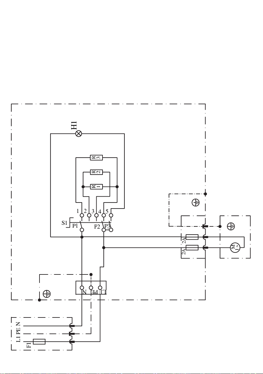
The electrical connections are to be made in accordance with both the applicable loca
and the VDE requirements by a qualified technician.
The mains connection is to be made using a rubber conduit attached to the appliance.
During installation, a connector must be installed between the appliance and the mains
so that all electrical lines running to the appliance can be disconnected for repair works
and cleaning. The contact openings on this connector must at least be of 3 mm
diameter. Voltage and current ratings are to be compared with the enclosed connection
diagram (circuit diagram). Care should be taken during installation that N-type and
grounded conductors are connected to the mains separately.
Page 7

Attention:
In case of exchanging the wiring cable, please use only cable made of silicon allowed for
continuous operation from – 50° C till + 180 ° C. In case of exchanging the mains lead;
please use oil-resistant and fire proved rubber conduits such as H07RN–F cable.
4.5 Handling in case of fire hazard
Should hot oil or similar inflame during operation, withdraw the power supply
immediately or disconnect all corresponding fuses !
Attention:
Do not try - under no circumstances - to extinguish the fire with water !
If anything, then use a blanket, a towel or something similar to extinguish the flames.
But a carbon dioxide fire extinguisher (CO2) would be best.
5 Cleaning of the device and the accessories
After use, thorough daily cleaning of the appliance is exceptionally quick and easy.
The procedure is as follows: Disconnect the appliance. After loosening the triangular
handle positioned at the housing, the housing and the heating elements can be swung
open by 180° or simply be lifted off their hinges. This renders access to the ceramic
reflector surface. We recommend the use of commercially available grill cleaning
products for stainless steel. Our devices are splash proved (IPX 4).
Attention:
The appliance may not be cleaned with a water jet, as for ex. a water hose or a pressure
sprayer, nor may it be -under no circumstances- submerged.
6 Disposal
When your appliance is worn out after reliable use over the years, you have the following
possibilities of its disposal :
1. Either dismount all electrical parts from the housing and take all appropriately
separated parts to your local collecting offices
2.Return the complete device to POTIS being the manufacturer and we will take care
of its expert disposal.
7 Error analysis
Should there be any electrical fault with your appliance, you may yourself carry out
following error analysis:
Please check the power supply of your connection box (are all corresponding fuses
operating correctly and are they all switched on ?)
Please particularly check if the heating elements, the supply or the plug show any
possible external defects for ex. in the insulation, scorches, defected parts or similar
Are all operating errors excluded, i.e. is the appliance switched on and are all switches
correctly set ? (Please have once again a look into the manual).
8 After-sales service
Of course, you may return the device to POTIS for repair and maintenance services,
as we dispose of all appropriate measuring and testing instruments, in order to carry out
and to guarantee a satisfactory repair.
Our recommendation:
Depending on the number of operating hours, your appliance should be checked by an
electrician at least every two years.
Page 8
8.1
Address
Potis GmbH & Co. KG Telefon: +49 (0) 551-50689- 0
August-Spindler- Strasse 4 Telefax: +49 (0) 551-50689-50
D-37079 Göttingen Internet: http://www.potis.de
E-Mail: [email protected]
9 Guarantee
6 months guarantee on materials, provided the appliance is installed and operated
properly.
10. Wiring diagram
 Loading...